
Nüttgens, M.; Feld, T.; Zimmermann, V.: Business Process Modeling with EPC and UML: Transformation or Integration?,
in: Schader, M.; Korthaus, A. (Hrsg.): The Unified Modeling Langua ge - Technical Aspects and Applications, Proceedings
(Mannheim, Oktober 1997), Heidelberg 1998, S. 250-261. URL: http://www.iwi.uni-
sb.de/nuettgens/Veroef/Artikel/umlepk/umlepk.ps
Business Process Modeling with EPC and UML
Transformation or Integration?
Dr. Markus Nüttgens,
Dipl.-Inform. Thomas Feld, Dipl.-Kfm. Volker Zimmermann
Institut für Wirtschaftsinformatik (IWi), Universität des Saarlandes,
Im Stadtwald, Gebäude 14.1, D - 66123 Saarbrücken,
phone. ++49 681 9762 228, fax ++49 681 77516,
email {nuettgens, feld; zimmermann}@iwi.uni-sb.de
Abstract: Process and object-orientation are basic concepts of modeling,
implementing and customizing information systems. In this paper we present two
approaches of combining those concepts into a coherent way. In the first
approach we discuss how to transform business process models (Event-driven
Process Chain (EPC) diagrams) into object-oriented models (Unified
Modeling Language (UML) diagrams). The main focus is to support the co-
existence of both modeling methods focusing on the modeling context. The
second approach deals with the integration of both modeling methods extending
the EPC-model by business object classes.
1 Business Modeling..............................................................................................................2
1.1 Event-driven Process Chain (EPC)..............................................................................2
1.2 UML Extension for Business Modeling. .......................................................................3
2 Transformation Approach: From the Event-driven Process Chain to the Unified Modeling
Language ..........................................................................................................................4
2.1 UML Use Case Diagrams ...........................................................................................4
2.2 UML Activity Diagram................................................................................................5
2.3 UML Class Diagram...................................................................................................5
2.4 UML Application Architecture ....................................................................................5
3 Integration Approach: „The Object-oriented Event-driven Process Chain (oEPC)“.............10
4 Conclusion........................................................................................................................11

Seite 2
1 Business Modeling
Today, analysis and design of business processes are the major tasks of business
engineering [Scheer (1994), Österle (1997), Hammer et al. (1993), Davenport (1993)]. In
research as well as in practice, the Architecture of integrated Information Systems (ARIS)
[Scheer (1992)] is accepted as a standard framework for business process (re-)engineering. It
supports the whole process management life cycle consisting of process design, process
management, process workflow and process application implementation [Scheer
(1996)]. The Unified Modeling Language (UML) [Rational Software (editor) (1997)] is a
common standard for object-oriented modeling. The UML is derived of a shared set of
commonly accepted concepts which have successfully been proven in the modeling of large
and complex systems, especially software systems. With the UML extension for business
modeling, a first object-oriented UML terminology has been defined for the domain of
business modeling. ARIS as well as UML are based on integrated meta models supported by
several modeling tools. The core business modeling concepts of both methodologies will first
be introduced and compared afterwards.
1.1 Event-driven Process Chain (EPC)
The method of Event-driven Process Chains (EPC) [Keller et al. (1992), Nüttgens (1997)]
has been developed within the framework of ARIS in order to model business processes. In
the EPC model, a process consists of sequences of events triggering business functions, which
are themselves the results of other functions apart from initial events triggering the whole
process. By introducing boolean operators (''and'', ''or'', ''exclusive or''), the event-driven
control structure can be expanded to a complex control flow illustrating business relevant
decisions.
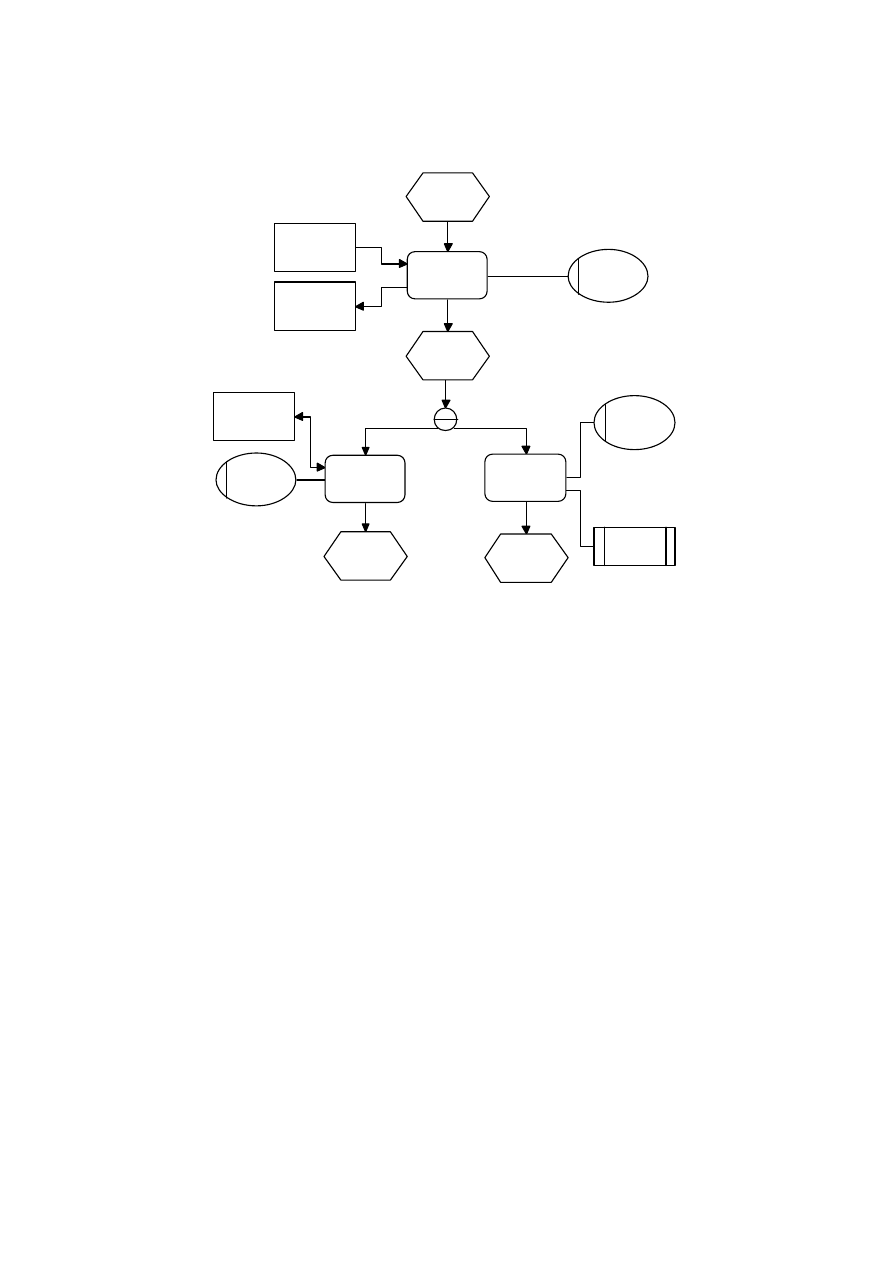
This basic model of the EPC can be extended by further semantic components of description.
The illustration of data flows, responsibility of organization units and the use of IT systems
are examples for such an extension (see figure 1). Furthermore, on the basis of formal
descriptions of the EPC method, tool-supported concepts for analysis and simulation are
being developed. The approach of Langner/Schneider/Wehler [Langner et al. (1997)] aims at
the translation of EPC models into petri networks and at the algorithmic verification of the
resulting networks. In contrast to this, the approaches of Rump [Rump (1997)] and of
Keller/Teufel [Keller and Teufel (1997)] are based on a formal description of the EPC.
Seite 3
event 0
function 1
event 1
function 2
function 3
event 2
event 3
information
object 2
information
object 1
information
object 3
organization
unit 1
organization
unit 1
organization
unit 2
IT system 1
input
output
executes
triggers
causes
causes
input/output
AND
causes
supports
executes
triggers
Figure 1: Event-driven process chain (EPC)
1.2 UML Extension for Business Modeling.
The UML extension for business modeling [Rational Software (editor) (1997)] consists of
several stereotypes and introduces an object-oriented terminology for business modeling.
The extension does not currently introduce any explicit tagged values or constraints and is
not meant to be a complete business modeling language at all.
On the top level, there is the use case model and the object model based on the UML meta
class model. Models are partitioned into constructs, based on the UML meta classes
subsystem and package.
The use case model describes the behavior and relationships between services and
participants outside the focused information system, e.g. customers and suppliers. The object
model focuses on the internal business processes. It consists of object systems, containing
organization units, work units, workers and entities. Figure 2 illustrates the entity trade in
two states [requested] and [processed], where the trade is processed by the trade
document work unit. Client trading is an action. The icons are designed to be meaningful in
the particular problem domain. Nevertheless, the diagram is based on UML elements, using
other symbols and another terminology. Hence, we do not go further in detail concerning the
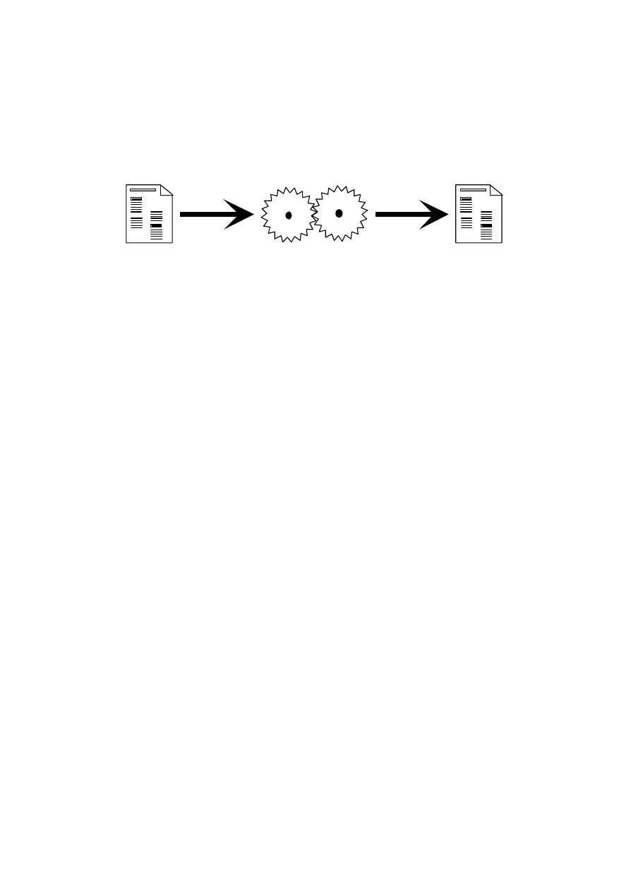
Seite 4
UML extension for business modeling, but compare the EPC directly with class and
behavior diagrams of the UML in order to show contradictions and synergy.
Trade
[requested]
Client
Trading
Trade
[processed]
Figure 2: Example of special icons for entities and actions [Rational Software editor) (1997)]
2 Transformation Approach: From the Event-driven
Process Chain to the Unified Modeling Language
As we have mentioned above, the EPC method and UML have different scopes of business
modeling. Hence, it is not clear whether the results of the EPC method substitute the UML
results or whether the methods are compatible at all. In this section, we describe an
transformation approach which shows exemplary relationships between the EPC and the basic
UML diagrams use case, activity diagram, class diagram and the UML application
architecture at all. We give a short description of the UML diagram, followed by the
comparison with the EPC and a rough transformation from EPC to UML.
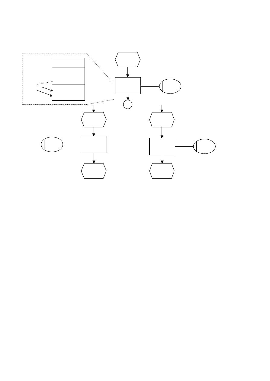
2.1 UML Use Case Diagrams
Use case diagrams primarily define the behavior of a system or subsystem. Instances of the
actors can use services of the system in any chronological order. The internal structure of the
system, which makes the services available, can be regarded as a black box.
The relationship and interaction of organization units and business functions can also be
illustrated using an EPC-diagram. Moreover, the control flow is illustrated and scenarios can
be linked to complex process models in EPC.
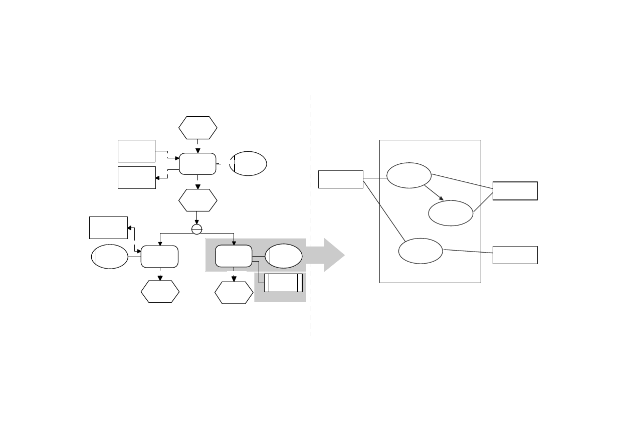
Use cases can be regarded as a representation of small and less structured business functions
on a very detailed level, where is no need to define a control flow. Furthermore, collecting all
references from an application system to all functions and organizational units concerned,
a use case diagram for the application system can be made up. An example for the
transformation is shown in figure 3.

Seite 5
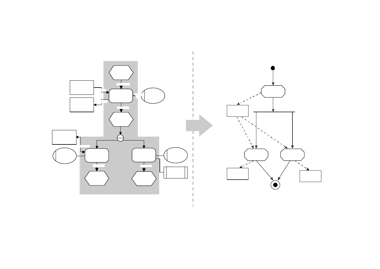
2.2 UML Activity Diagram
An activity diagram is a combination of the control flow and object flow among its
constituent actions, similar to the control flow and the data flow among the functions in the
EPC. Thus, most of the EPC diagram constructs can be more or less easily transformed into
activity diagrams. EPC functions provoke activities, EPC events cause object flow
states and EPC link operators lead to synchronized or splitted transitions. Figure 4
illustrates those relationships. Because of the illustrative design of control flow and data flow,
both models can also be applied in the context of workflow modeling.
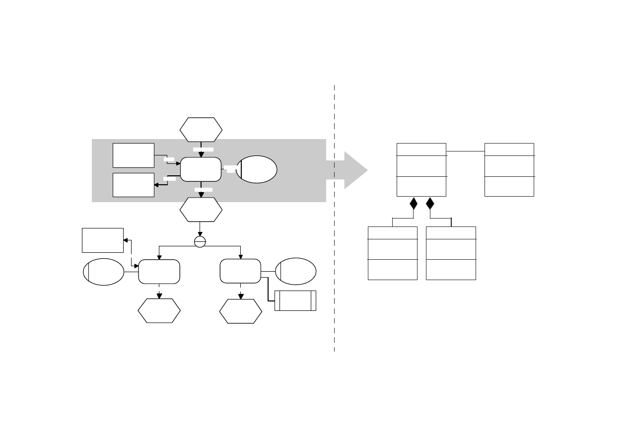
2.3 UML Class Diagram
Although class diagrams describe the static structure of an information system, processes give
a lot of information on objects, their structure and their relationships. Classes can be derived
from information objects and business functions of EPC-diagrams by detailing them.
Within ARIS, the Entity- Relationship Model (ERM) or function decomposition diagrams
can be used to discribe the static stucture. As shown in Figure 5, classes are not necessarily
developed in a top down approach but can be derived in parallel to a business process model.
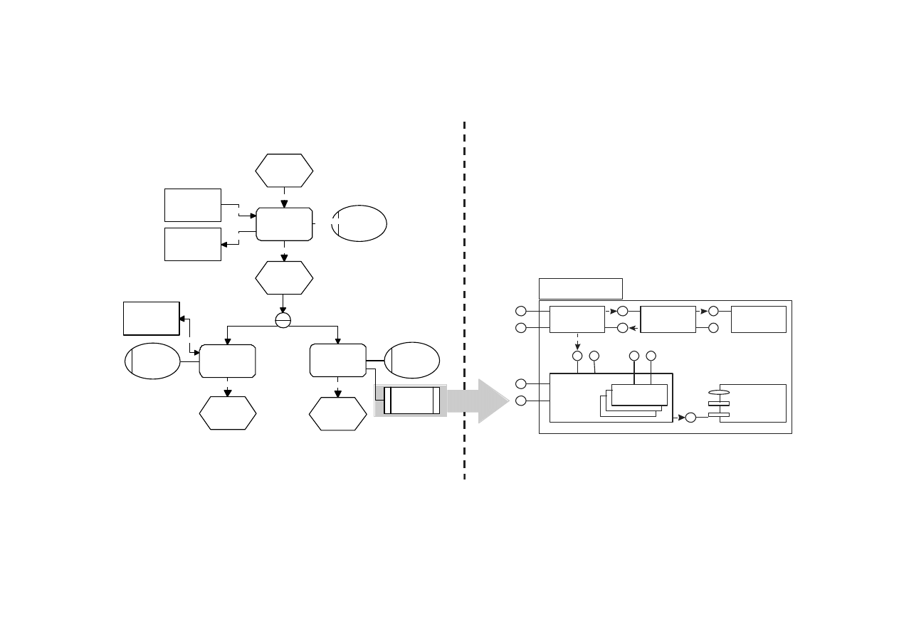
2.4 UML Application Architecture
A general grouping mechanism of the UML application architecture is provided by the
subsystem and the package constructs. An application system can be modularized in
subsystems and packages.
In an EPC diagram, the existing applications are described as an IT-resource, related to
other kinds of resources like organization units and information objects.
The relationship between applications and business functions and their support of complex
business processes are also illustrated in the EPC diagram. Application systems defined in
an EPC model are the basis for describing their interaction. Furthermore, in an application
architecture diagram, application components can be represented by several UML
packages. Each package can be specified in greater detail with the help of further UML
diagrams, as it is indicated in figure 6.
Seite 6
actor 1
use
case 1
use
case 2
actor 2
use
case 3
actor 3
name of diagram
event 0
function 1
event 1
function 2
function 3
event 2
event 3
information
object 2
information
object 1
information
object 2
organization
unit 1
organization
unit 1
organization
unit 2
IT system
1
input
output
carries
out
triggers
causes
causes
causes
input/output
AND
Figure 3: EPC - UML Use Case Diagram transformation, see [Oestereich(1997)]
Seite 7
activity 1
activity 2
activity 3
object 1
[state A]
object 2
[state A]
object 1
[state B]
event 0
function 1
event 1
function 2
function 3
event 2
event 3
information
object 2
information
object 1
information
object 2
organization
unit 1
organization
unit 1
organization
unit 2
IT system
1
input
output
carries
out
triggers
causes
causes
causes
input/output
AND
Figure 4: EPC - UML activity diagram transformation
Seite 8
class 2
attribute 1
attribute 2
operation 1
operation 2
class 1
attribute 1
attribute 2
operation 1
operation 2
class 3
attribute 1
attribute 2
operation 1
operation 2
class 4
attribute 1
attribute 2
operation 1
operation 2
event 0
function 1
event 1
function 2
function 3
event 2
event 3
information
object 2
information
object 1
information
object 2
organization
unit 1
organizational
unit 1
organization
unit 2
IT system
1
input
output
carries
out
triggers
causes
causes
causes
input/output
AND
Figure 5: EPC - UML class diagram transformation
Seite 9
event 0
function 1
event 1
function 2
function 3
event 2
event 3
information
object 2
information
object 1
information
object 2
organization
unit 1
organization
unit 1
organization
unit 2
IT system
1
input
output
carries
out
triggers
causes
causes
causes
input/output
AND
application component
process
control
interaction
control
dialogue
control
fundamental
classes
business class
data
management
Figure 6: EPC - UML application architecture transformation

Seite 10
3 Integration Approach: „The Object-oriented Event-
driven Process Chain (oEPC)“
The purpose of the following presented concept of the object-oriented event-driven process
chain (oEPC) [Scheer et al. (1997)] is on the one hand to preserve the potential and the end
users acceptance of the standard EPC method and on the other hand to integrate object-
orientated methods.
In this context, a business process is defined as the event-driven processing and interaction of
business objects . The oEPC differentiates between business process, business object, the
corresponding resources such as organization units, IT and production resources and
rules/events.
Within the object-oriented methodology, business objects are regarded as generalized
objects which can usually be specialized. For instance, the business object customer order
can be specialized into the objects customer order header and customer order items. Often,
business objects are called object clusters or complex objects.
Events/rules describe the state transition of a business object at a certain time caused by the
execution of one of its operations. They are defined as independent meta objects. Within the
oEPC method business objects and events/rules are defined as object classes on type level.
Hence, business objects can be described in greater detail by assigning attributes and
operations to the classifying business object class.
Business process modeling focuses on finding and solving organizational problems and media
incompatibilities in business processes. For this reason, organization units and resources can
be assigned to business objects similar to the standard EPC method.
The interaction between business objects is based on message exchange. Messages reflects
the control flow i.e. the decision- and control mechanism of a business process.
Messages can also describe a kind of customer-supplier-relationship of business objects.
The message sender (customer) triggers the recipient (supplier) to produce a result, which the
sender needs for the further execution of the process. But within business process modeling,
customer-supplier-relationships do not come to the fore.
Furthermore, the EPC method disposes of a set of boolean operators, used to split a
process or to combine different processes. Hence, the business decision interrelationship
within the process execution can be illustrated.
The combination of boolean operators and events/rules make up the link to common
business roles in analogy to the standard EPC.
In figure 7, the structure of a business process model is shown by means of oEPC symbols
illustrating graphically the control flow defined by event-driven messages.
Seite 11
business
object class 1
AND
event class 0
event class 1
event class 2
business
object class 3
business
object class 2
event class 3
event class 4
organization
unit 1
organization
unit 2
organization
unit 3
triggers
triggers
triggers
triggers
triggers
executes
executes
executes
triggers
triggers
Figure 7: Example for the oEPC structure of a business process model
Because of the complementary usage of object attributes and object operations, the
transformation of an oEPC model into the static UML class diagram is possible and can be
the basis of a further coherent implementation specification.
4 Conclusion
Concepts for the modeling of the static structure of object classes, e.g. UML class diagrams,
are methodically sophisticated approaches which are increasingly used in practice and which
will probably replace other traditional approaches for static modeling like the entity
relationship modeling language.
Even today, usefully adapted and simplified object-oriented languages for static modeling can
be used in the context of business modeling. In addition to this, trough refinement and
consideration of IT relevant aspects, the business model can be transformed into an
implementation specification.
business objcect
class 1
operation o1
operation o2
operation o3
attribute a1
attribute a2
attribute a3
inactive

Seite 12
The object-oriented modeling of dynamic behavior, especially within business processes, and
the relationships between dynamic diagrams and static class diagrams are just insufficiently
analyzed and discussed.
The main UML diagram framework still focuses on the implementation specification whereas
the recent UML extensions for business modeling just introduce other symbols for the existing
diagram structures. Thus, the UML extensions for business modeling can hardly be used for
business process modeling.
The presented transformation approach as well as integration approach are based on the
idea of finding a synergetic combination of process- and object-oriented concepts in order to
profit from the advantages of both meth- ods. This idea, which is also increasingly used in
literature, is changing the rather dogmatic discussion on methods into an discussion on
integration of methods.
The further scientific work within the context of the presented object-oriented event-driven
process chains (oEPC) will primarily deal with the development of a coherent proceeding
model and the illustration with the help of modeling tools.
References
DAVENPORT, T.H. (1993): Process Innovation. Reengineering Work through Information
Technology, Boston.
HAMMER, M.; CHAMPY, J. (1993): Reengineering the Corporation. A Manifesto for
Business Revolution, New York.
KELLER, G.; NÜTTGENS, M.; SCHEER, A.-W. (1992): Semantische Prozeßmodellierung
auf der Grundlage ''Ereignisgesteuerter Prozeßketten (EPK)'', Veröffentlichungen des Instituts
für Wirtschaftsinformatik, Heft 89, Saarbrücken, URL: http://www.iwi.uni-sb.de/public/iwi-
hefte/heft089.zip.
KELLER, G.; TEUFEL, T. (1997): R/3 prozeßorientiert anwenden: Iteratives
Prozeßprototyping zur Bildung von Wertschöpfungsketten, 2. edition, Bonn.
LANGNER, P.; SCHNEIDER, C.; WEHLER (1997): Prozeßmodellierung mit
ereignisgesteuerten Prozeßketten (EPKs) und Petri-Netzen, Wirtschaftsinformatik 39, 479-
489.
NÜTTGENS, M. (1997): Event-driven Process Chain (EPK) - Some Links and Selected
Publications, URL: http://www.iwi.uni-sb.de/nuettgens/EPK/epk.htm.
OESTEREICH, B. (1997): Objektorientierte Softwareentwicklung mit der Unified Modeling
Language, 3. edition, München 1997, 85ff.
ÖSTERLE, H. (1997): Business Engineering, Prozeß - Systementwicklung, Volume 1:
Entwurfstechniken, Berlin.

Seite 13
RATIONAL SOFTWARE (editor)(1997): UML Notation Guide 1.1, Unified Modeling
Language Version 1.1, Santa Clara (USA), URL:
http://www.rational.com/uml/documentation.html.
RATIONAL SOFTWARE (editor)(1997): UML Extension for Business Modeling version
1.1, Unified Modeling Language version 1.1, Santa Clara (USA), URL:
http://www.rational.com/uml/documentation.html.
RUMP, F. (1997): Erreichbarkeitsgraphbasierte Analyse ereignisgesteuerter Prozeßketten,
Technischer Bericht, Fachbereich Informatik, Universität Oldenburg,URL: http://www-
is.informatik.uni-oldenburg.de/~rump/paper/analyse/analyse.ps.
SCHEER, A.-W. (1992): Architecture of Integrated Information Systems - Foundations of
Enterprise-Modeling, Springer, Berlin.
SCHEER, A.-W. (1994): Business Process Engineering - Reference Models for Industrial
Enterprises, 2nd edition, Springer, Berlin.
SCHEER, A.-W. (1996): ARIS-House of Business Engineering, Veröffentlichungen des
Instituts für Wirtschaftsinformatik, Heft 133, Saarbrücken, URL: http://www.iwi.uni-
sb.de/public/iwi-hefte/heft133.zip.
SCHEER, A. W.; NÜTTGENS, M.; ZIMMERMANN, V. (1997): Objektorientierte
Ereignisgesteuerte Prozeßkette (oEPK) - Methode und Anwendung, Veröffentlichungen des
Instituts für Wirtschaftsinformatik, Heft 141, Saarbrücken, URL: http://www.iwi.uni-
sb.de/public/iwi-hefte/heft141.ps.
Wyszukiwarka
Podobne podstrony:
Workflow, Business Process Modeling Notation
Business modeling with UML id 9 Nieznany (2)
Advanced Modeling with UML (OMG)
Process Modeling, Simulation, and Control for Chemical Engineers 2E
Processing, Modeling
Farina Reproduction of auditorium spatial impression with binaural and stereophonic sound systems
11 3 2 3 Lab Testing Network Latency with Ping and Traceroute
Modeling with shrinkage during the vacuum drying of carrot (daucus carota) (Arévalo Pinedo, Xidieh M
(WinD Power) Dynamic Modeling of Ge 1 5 And 3 6 Wind Turbine Generator {}[2003}
Business Process Reengineering, ZARZADZANIE WSB W
M Kaufmann Programming Cameras and Pan tilts With DirectX and Java fly (2)
Applying Principles of Neurodevelopment to Clinical Work with Maltreated and Traumatized Children
więcej podobnych podstron