Adjustable
Fuel Pressure
Regulator
Installation Instructions for:
Part Numbers
25-300
25-301
25-303
25-304
U.S. Patent # 6,298,828
WARNING:
,!
Due to the fact that this installation deals with your fuel system
this installation is not for the mechanically challenged! If you are
not mechanically inclined or do not understand the procedure
please do not attempt the installation. Refer the installation to a
reputable mechanic.
ADVANCED ENGINE MANAGEMENT INC.
2205 126
TH
Street, Unit A Hawthorne, CA. 90250
Phone: (310) 484-2322 Fax: (310) 484-0152
Http://www.aempower.com
Part Number: 10-290
© 2000 Advanced Engine Management, Inc.
This part is legal in California for racing vehicles ONLY and should NEVER be used on public highways.
Congratulations! You have just purchased the finest adjustable fuel pressure regulator for
your car at any price!
AEM billet aluminum adjustable pressure regulator.
The AEM adjustable regulator bolts directly to the stock Honda or the AEM high volume fuel rail.
It is CNC machined from 6061 T-6 aluminum. The fuel outlet port is tapped to 9/16-18 threads,
which allows the use of several different hoses ranging from the stock Honda fuel return hose to
–8 AN hose. The vacuum reference is 1:1 ratio so for every pound of boost on a turbocharged
or supercharged application yields a 1-pound rise in fuel pressure. The range of adjustability is
from 20 PSI to the maximum the fuel pump can deliver.
A unique feature of the AEM adjustable pressure regulator is that the discharge port in the
regulator is changeable. This allows the user to tailor the regulator return volume to match their
fuel pump. A common problem that occurs when using a fixed orifice in a “universal” regulator is
that the fuel pressure cannot be effectively controlled when the fuel pump volume is significantly
higher than stock. In the case of too small of a discharge orifice, there is a large pressure spike
associated with rapid deceleration because the orifice cannot flow enough fuel when the
diaphragm is fully deflected to the open position. This causes a momentary rich condition, which
may lead to a rough idle quality until the pressure stabilizes. Conversely if the discharge orifice
is too large the adjustment is difficult because the response of the fuel flow out of the orifice is
too rapid which makes the adjustment screw too sensitive. The AEM regulator is packaged with
three orifice sizes, .100”, .150” and .200”. They are easily changed by removing the diaphragm,
unscrewing the orifice, and replacing it with the desired size orifice. The size range provided
with the kit is enough to cover any pump from a stock Honda pump to the largest after-market
pump available. The replaceable orifices are color coded for easy identification.
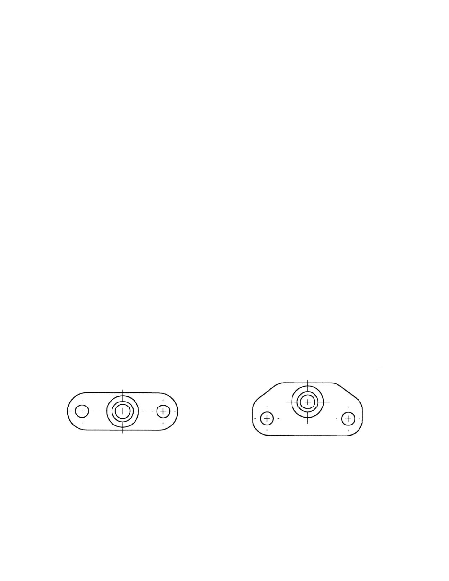
Offset
Base
Inline
Base
Note: Honda uses two styles of fuel pressure regulator bases. Before proceeding with
your installation please compare the fuel pressure regulator on your vehicle and your
new AEM adjustable fuel pressure regulator with the above diagrams.
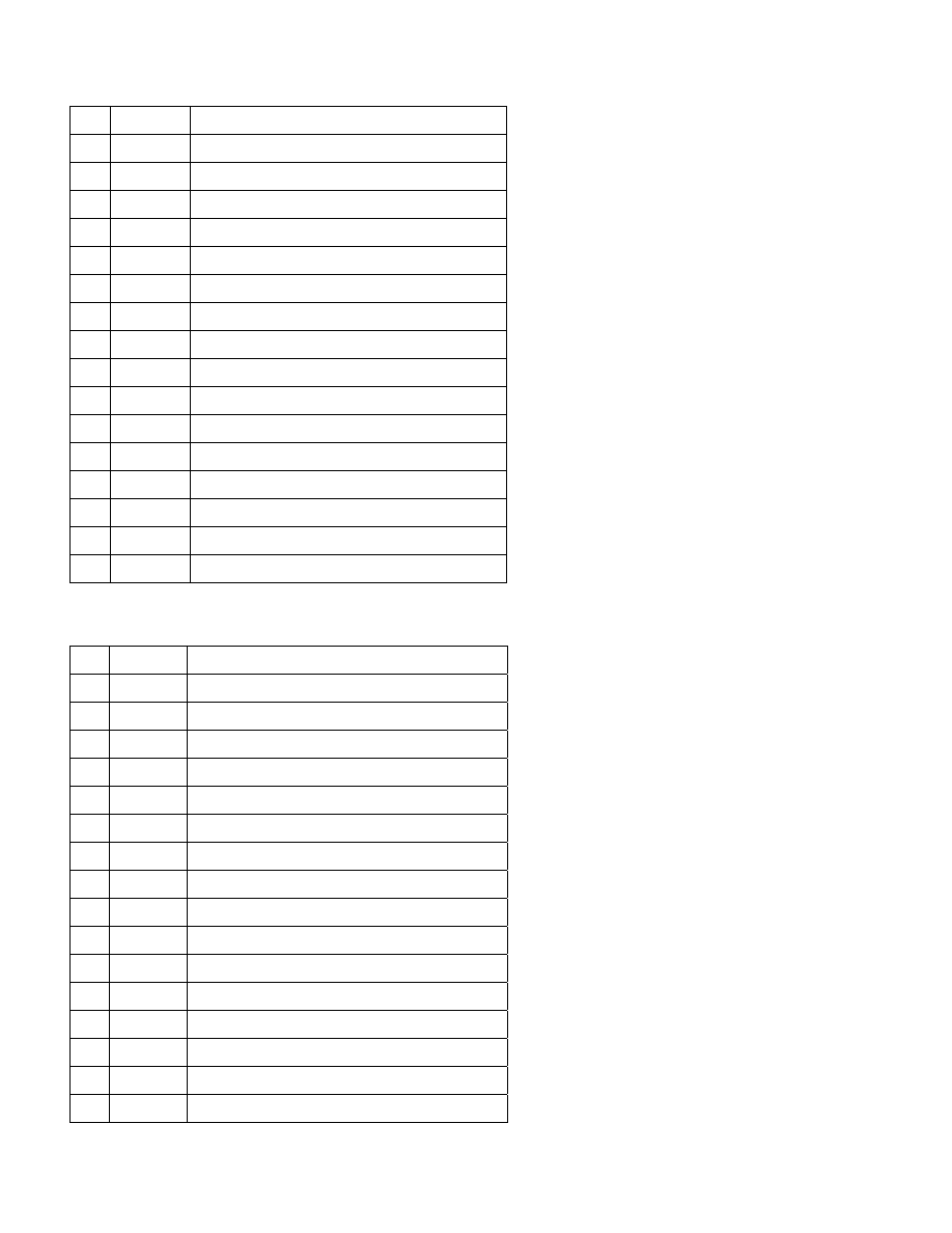
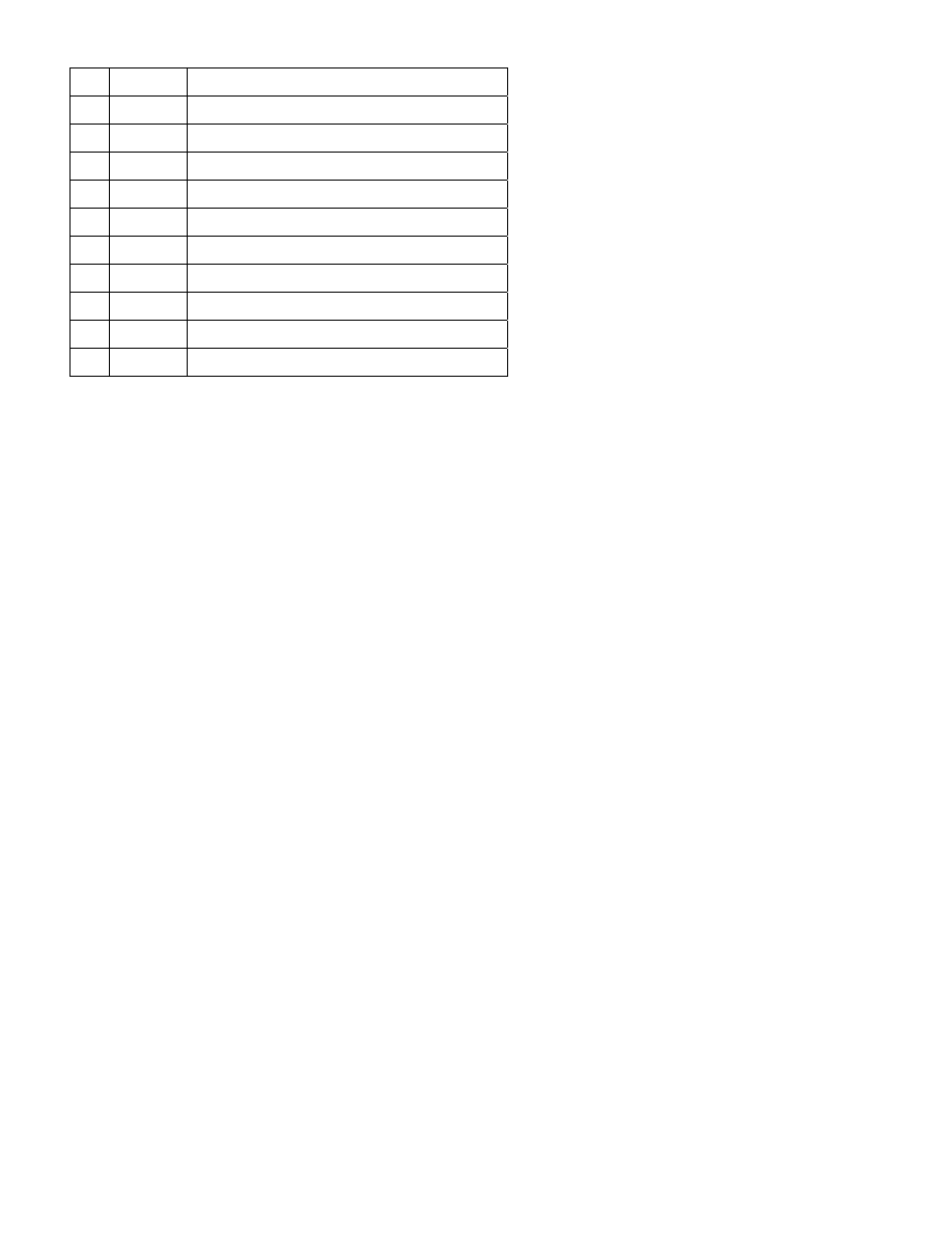
Bill of Materials for 25-300:
2
2-609
-6 to 7mm Barb Fuel Return Fitting
1 2-611
Vacuum
Fitting
1 2-612
Spring
Cap
1 2-698
.250ORIFICE,BALLPRESSREG
1 2-697
.175ORIFICE,BALLPRESSREG
1 2-696
.1OrificeBALLPRESSREG
1
2-8000
Fuel Pressure Regulator Top
1
2-8100
Fuel Pressure Regulator Bottom (Inline)
1 1-3007
Crush
Washer
1 1-3010
O-Ring
6
1-2023
Socket Bolt, SS 8-32 x 5/16”
1
1-2021
Socket Screw, SS 10-32 x 1”
1
1-2022
Nut, Jam SS 10-32
1 2-301
Diaphragm
1 1-122
Spring
2
1-2045
Socket Bolt, SS M6 x1 x 12mm
2
1-3016
Washer, SS M6
Bill of Materials for 25-301:
1
2-609
-6 to 7mm Barb Fuel Return Fitting
1 2-611
Vacuum
Fitting
1 2-612
Spring
Cap
1 2-613
0.20”
Orifice
1 2-614
0.15”
Orifice
1 2-615
0.10”
Orifice
1
2-8000
Fuel Pressure Regulator Top
1
2-8101
Fuel Pressure Regulator Bottom (Offset)
1 1-3007
Crush
Washer
1 1-3010
O-Ring
6
1-2023
Socket Bolt, SS 8-32 x 5/16”
1
1-2021
Socket Screw, SS 10-32 x 1”
1
1-2022
Nut, Jam SS 10-32
1 2-300
Diaphragm
1 1-122
Spring
2
1-2045
Socket Bolt, SS M6 x1 x 12mm
2
1-3016
Washer, SS M6
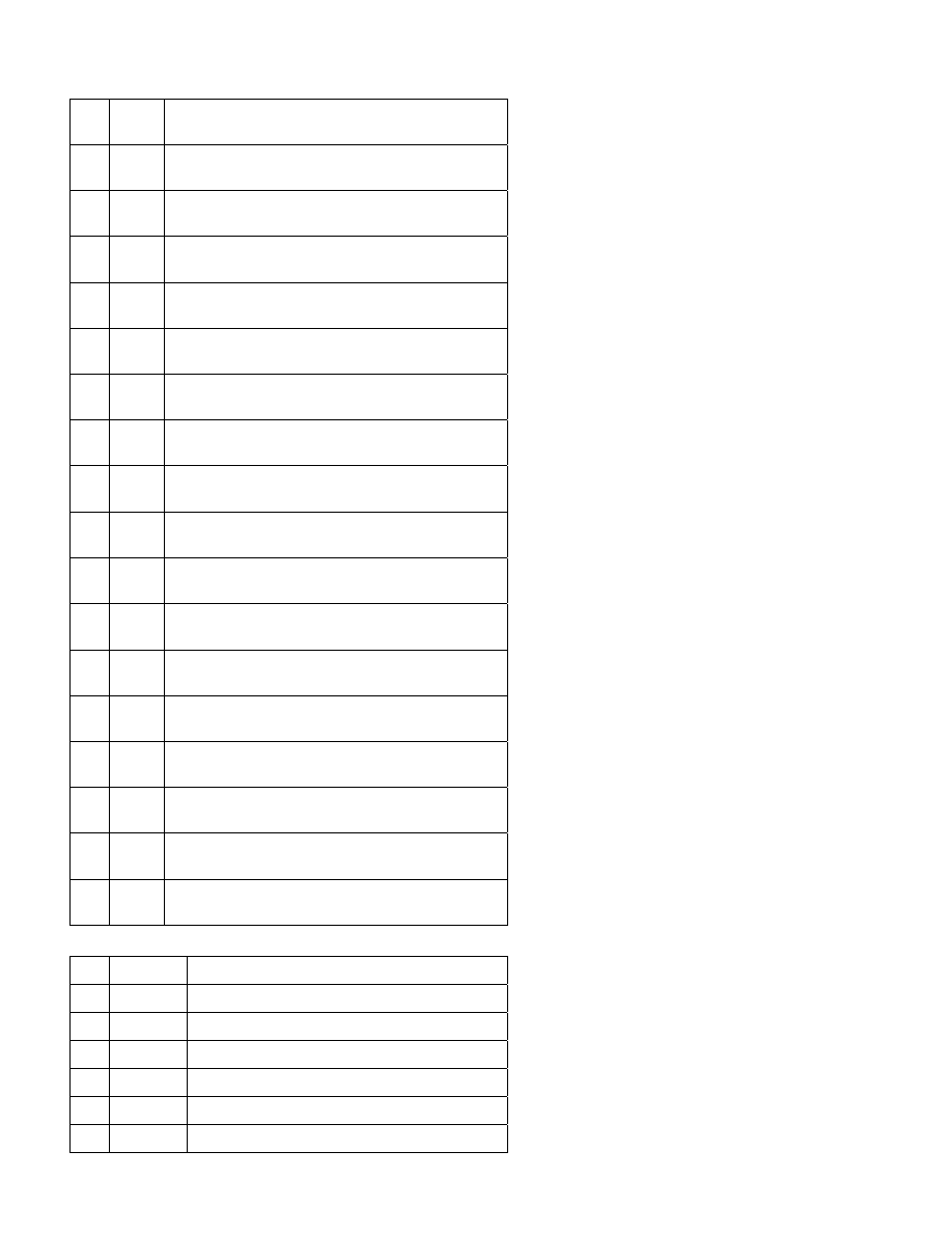
Bill of Materials for 25-303:
1 2-
610
-6 to 7mm Nipple
1 2-
635
-6 Banjo Bolt
1 2-
611
Vacuum Fitting
1 2-
612
Spring Cap
1 2-
698
.250 Orifice
1 2-
697
.175 Orifice
1 2-
696
.1 Orifice
1 2-
8000
Fuel Pressure Regulator Top
1 2-
8100
Fuel Pressure Regulator Bottom (Inline)
2 1-
3007
Crush Washer
1 1-
3010
O-Ring
6 1-
2023
Socket Bolt, SS 8-32 x 5/16”
1 1-
2021
Socket Screw, SS 10-32 x 1”
1 1-
2022
Nut, Jam SS 10-32
1 2-
300
Diaphragm
1 1-
122
Spring
2 1-
2045
Socket Bolt, SS M6 x1 x 12mm
2 1-
3016
Washer, SS M6
Bill of Materials for 25-304:
1
2-610
-6 to 7mm Nipple
1
2-635
-6 Banjo Bolt
1 2-611
Vacuum
Fitting
1 2-612
Spring
Cap
1 2-613
0.20”
Orifice
1 2-614
0.15”
Orifice
1 2-615
0.10”
Orifice
1
2-8000
Fuel Pressure Regulator Top
1
2-8101
Fuel Pressure Regulator Bottom (Offset)
2 1-3007
Crush
Washer
1 1-3010
O-Ring
6
1-2023
Socket Bolt, SS 8-32 x 5/16”
1
1-2021
Socket Screw, SS 10-32 x 1”
1
1-2022
Nut, Jam SS 10-32
1 2-300
Diaphragm
1 1-122
Spring
2
1-2045
Socket Bolt, SS M6 x1 x 12mm
2
1-3016
Washer, SS M6
Read and understand these instructions BEFORE attempting to install this product
WARNING!!!
• Do not smoke while working on the fuel system.
• Keep open flames or sparks away from your work area.
•
Be sure to relieve fuel pressure while engine is off.
Note: 1990-1993 Honda Accord and 1992-2000 Honda Prelude require the use of the AEM Hi-Flow Fuel Rail
P/N 25-104. The AEM Adjustable Fuel Pressure Regulator can NOT be used with the stock fuel rail on these
applications.
Note: Refer to attached table of applications to determine the correct AEM Adjustable Fuel Pressure
Regulator Kit that is required for your year/model vehicle.
1)
Getting started
a) Make sure vehicle is parked on a level surface.
b) Set parking brake.
c) Disconnect the negative cable from the negative battery terminal.
d) If engine has run within the past two hours let it cool down.
e) Clean the area on the fuel rail adjacent to the regulator.
Note: It is recommended to replace the washer between the service bolt and the special banjo bolt whenever the
service bolt is loosened. (where equipped)
2)
Relieving fuel pressure
a) Remove the fuel fill cap.
b)
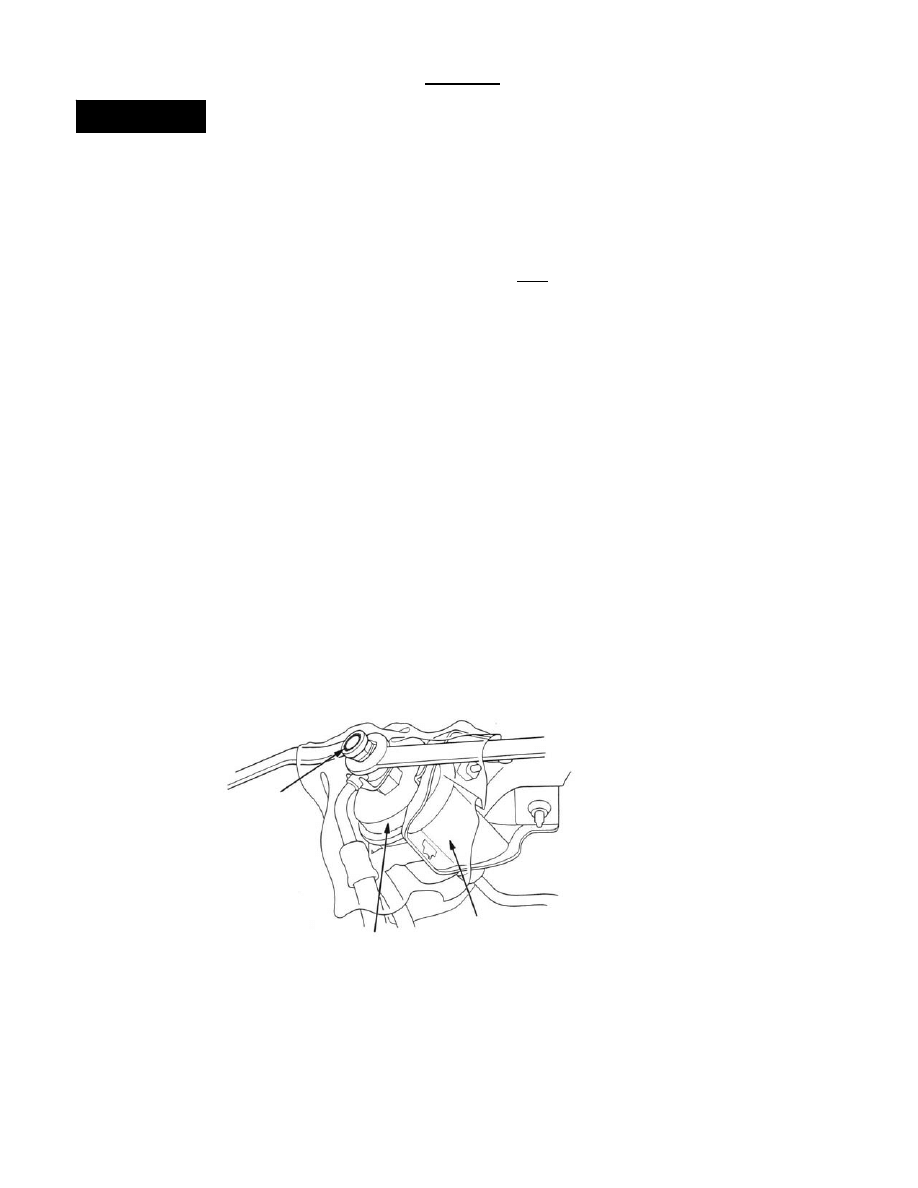
On models equipped with a 6mm service bolt. (Illustrated below) If your vehicle is
not equipped with a 6mm service bolt, proceed to step c.
i)
Use a box end wrench on the 6mm service bolt on top of the fuel filter, while holding the special banjo
bolt with another wrench.
ii) Place a rag or shop towel over the 6mm service bolt.
iii) Slowly loosen the 6mm service bolt one complete turn.
iv) Leave service bolt loose until all pressure has been relieved.
v) Tighten service bolt to 10 lbf-ft.
Shop Towel
Fuel Filter
Service Bolt
10 lbf
z
ft
c)
On models not equipped with a 6mm service bolt.
i)
Use a box end wrench on the 12mm banjo bolt on top of the fuel filter.
ii) Place a rag or shop towel over the 12mm banjo bolt.
iii) Slowly loosen the 12mm banjo bolt one complete turn or until all pressure has been relieved.
iv) Torque the 12 mm banjo bolt to 25 lbf-ft.
3)
Stock fuel pressure regulator removal
a) Place a rag or shop towel under the fuel pressure regulator return line.
b) Disconnect the fuel return line at the bottom of the stock fuel pressure regulator.
c) Disconnect the vacuum hose from the stock fuel pressure regulator.
d) Place a rag or shop towel over the fuel pressure regulator.
i)
Remove the two 6mm retaining bolts.
ii) Remove the fuel pressure regulator from the vehicle.
The AEM adjustable fuel pressure regulator has been set to 40psi using a
typical Honda fuel pump and a perfect running fuel system. Due to the
differences on vehicle fuel pressure on different applications it is highly
recommended that you adjust the fuel pressure on your vehicle. Refer to the
last page of the instructions for the factory recommended fuel pressures.
WARNING!!!
4)
Installation of the AEM adjustable fuel pressure regulator
Note: The AEM fuel pressure regulator has the .100” orifice installed in the regulator and is set to
40psi. All adjustments of the pressure regulator will be explained in a later portion of the instructions.
a) Remove and discard the two fuel pressure regulator caps used in packing.
i)
Note: One cap is in the fuel inlet and one cap is on the fuel return.
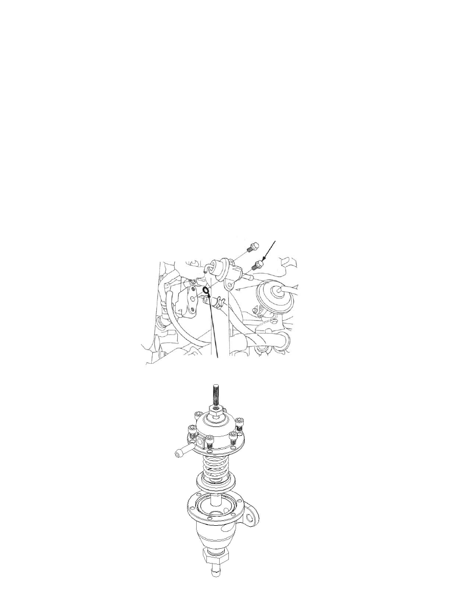
b) Install the fuel pressure regulator onto the fuel rail using the two allen bolts and washers supplied in the kit.
Make sure that the o-ring is replaced and properly installed between the regulator and the fuel rail
.
i)
Note: When installing the two allen head bolts a 5mm allen key should be used.
ii) Torque to 9 lbf-ft.
c) Connect the vacuum hose to the top of the fuel pressure regulator. On some vehicles incorporating a
strut tower brace, it may be required to rotate the pressure regulator top to clear vacuum fitting.
d) Install the fuel return line fitting.
i)
Use one crush washer when using the inline return fitting. Tighten to 20 lbf-ft. (Kits 25-300 & 25-301)
ii) Use two crush washers (one on each side of the fitting) when using the banjo angle return fitting.
Tighten to 20 lbf-ft. (Kits 25-303 & 25-304)
(1) When using a kit with an angle return fitting, rotate the return nipple to match the fuel return line
placement before tightening.
e) Make sure that the rubber fuel return line is free flowing back to the fuel return hard line.
(1) Note: Ensure that there are no bends or kinks in the line that can restrict the fuel flow.
f) Install any remaining components that were removed during disassembly.
5)
Finishing touches
a) Connect the negative battery terminal.
b) Turn the ignition switch to the on position for approximately two seconds. Do not operate the starter.
Then turn the ignition switch to the off position.
c) Repeat this procedure three times, and then check all components that were removed during installation for
any signs of fuel leakage.
d) If there are signs of leakage you MUST correct the leak before proceeding.
e) If there are no signs of leakage, then start engine and again check for leaks. If there is any sign of leaking
you MUST repair the leak before driving the vehicle.
f) Note: To check the fuel pressure, start the engine. Measure the fuel pressure with the engine idling
and vacuum hose of the fuel pressure regulator disconnected from the fuel pressure regulator and
pinched. Set the AEM adjustable fuel pressure regulator to recommended settings on the last page
of the instructions.
6)
Pressure and orifice adjustments
Note: The AEM adjustable fuel pressure regulator can be fine tuned for your application. These
adjustments will be covered in this section. A fuel pressure gauge needs to be used for precise tuning.
a) When fuel pressure adjustments are to be made, loosen the jam nut on the top of the AEM fuel pressure
regulator and either tighten or loosen the set screw.
i)
When loosening the jam nut a 3/8” wrench should be used.
ii) When tightening or loosening the set screw a 3/32” allen key should be used.
(1) To increase fuel pressure turn the set screw in a clockwise rotation.
(2) To decrease fuel pressure turn the set screw in a counter-clockwise rotation.
b) When orifice changes are to be made, remove the fuel pressure regulator using the steps in section 4 in
reverse order. When this is completed, remove the six bolts from the top of the fuel pressure regulator and
use a 3/8” socket to remove the orifice in the regulator and replace with a different size orifice.
i)
When removing the six bolts from the top of the fuel pressure regulator a 9/64” allen key should be
used.
(1) Torque to 24 lbf-in.
(2) There is a constant pressure applied to the diaphragm by the spring inside the fuel regulator make
sure parts do not get lost upon removal of these bolts.
ii) When ever the regulator is disassembled check the diaphragm for any wear and tear, which may cause
a fuel pressure problem.
(1) If the diaphragm is damaged contact AEM to purchase a replacement diaphragm.
iii) When removing the orifice a 3/8” socket should to be used.
(1) Note: Be careful not to scratch or damage the surface of the orifice in any way, as it is a
precision ground surface for the diaphragm to seal on.
(2) Torque to 10 lbf-ft.
(3) There are three different size orifices supplied in the AEM fuel pressure regulator kit, which are
indicated by three different colors. Black = .100” Silver =.150” Gold = .200”
(4) Upon re-installation of the orifice use a light coat of oil on the threads to prevent galling.
iv) Re-assemble the fuel pressure regulator. Assembly diagram at the end of the instructions.
Shown below is a typical installation picture that can be used for reference.
Other applications are similar.
O-Ring
(Replace)
Torque to 9 lbf
z
ft
Fig. 1
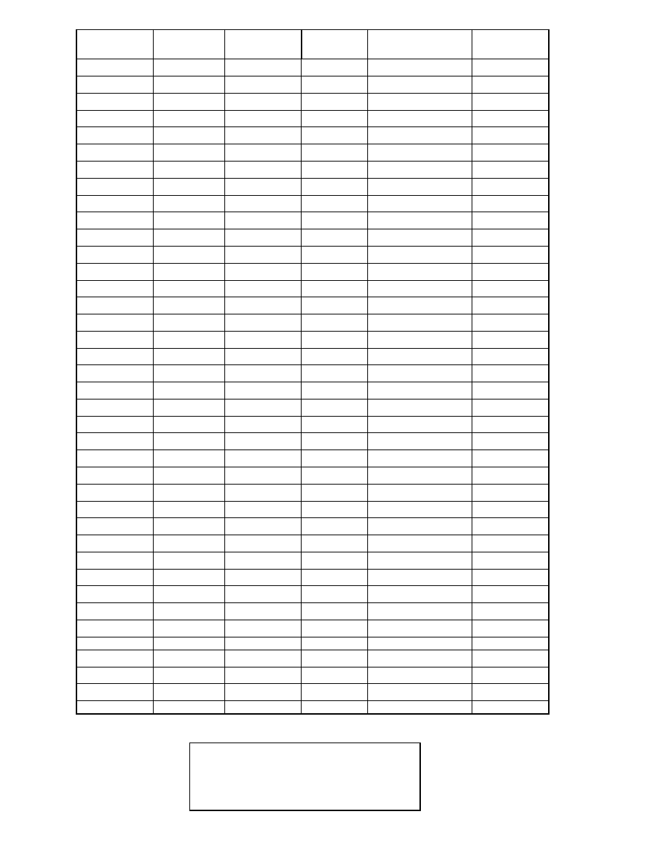
Regulator Part
#
Straight or
Angle Return
Vehicle
Year
Model
Rec. Fuel
Press
25-300
Straight
Integra
94-2000
RS, LS, GS
40-47 PSI
25-300
Straight
Integra
94-2000
GSR, Type-R
48-55 PSI
25-300
Straight
Accord
88-89
LXI, SEI
36-41 PSI
25-300
Straight
Accord
90-91
All
35-41 PSI
25-300
Straight
Accord
92-93
All
40-47 PSI
25-300
Straight
Civic
92
All
40-47 PSI
25-300
Straight
Civic
92-95
All
40-47 PSI
25-300
Straight
Civic
99-00
SI
40-47 PSI
25-300
Straight
Del Sol
93-95
S, SI
40-47 PSI
25-300
Straight
Del Sol
94-97
VTEC
40-47 PSI
25-300
Straight
Prelude
88-91
SI
35-41 PSI
25-300
Straight
Prelude
92-96
S
40-47 PSI
25-303
Angle
Integra
86-89
All
35-41 PSI
25-303
Angle
Integra
90-91
All
35-41 PSI
25-303
Angle
Integra
92-93
Non-VTEC
41-48 PSI
25-303
Angle
Integra
92-93
VTEC
48-56 PSI
25-303
Angle
NSX
91-94
All
46-53 PSI
25-303
Angle
NSX
95-00
All
46-53 PSI
25-303
Angle
TL
95-98
4 Cyl.
43-50 PSI
25-303
Angle
TL
96-98
V6
38-45 PSI
25-303
Angle
Vigor
92-94
All
43-50 PSI
25-303
Angle
Civic
89-91
SI
40-47 PSI
25-303
Angle
Civic
90-91
EX
40-47 PSI
25-303
Angle
Civic CRX
88-91
HF, SI
40-47 PSI
25-303
Angle
Insight
00
All
40-47 PSI
25-300
Straight
Prelude
92-96
SI, SE
36-43 PSI
25-300
Straight
Prelude
92-96
VTEC
33-40 PSI
25-300
Straight
Prelude
97-00
All
40-47 PSI
25-301
Straight
CL
98-99
2.3L
47-54 PSI
25-301
Straight
Accord
98-00
4 Cyl.
47-54 PSI
25-301
Straight
Civic
96-00
DX, HX, CX, LX
40-47 PSI
25-301
Straight
CRV
99-00
All
40-47 PSI
25-301
Straight
Del Sol
96-97
S
40-47 PSI
25-301
Straight
S2000
00
All
47-54 PSI
25-304
Angle
CL
97
2.2L
41-48 PSI
25-304
Angle
Accord
94-97
4 Cyl.
41-48 PSI
25-304
Angle
Civic
96-00
EX
40-47 PSI
25-304
Angle
CRV
97-98
All
38-46 PSI
25-304
Angle
Del Sol
96-97
SI
40-47 PSI
For Technical Inquiries
Please E-Mail us at
Tech@aempower.com
Document Outline
Wyszukiwarka
Podobne podstrony:
Fuel Fuel pressure hose replacement
ARTICLE FUEL PRESSURE CIRCUIT DIAGNOSTIC
SI Replacement of Fuel Pressure Hoses
fuel pressure
Genetyka regulacja funkcji genow
Pressure%20Cem[1]
REGULACJA UKLADU KRAZENIA 2
33 Przebieg i regulacja procesu translacji
8 ocena jakości układów regulacji
WYKŁAD 11 SPS 2 regulatory 0
WYKŁAD 7 Szeregowy regulacja hamowanie
Wzajemna regulacja gruczołów wydzielania wewnętrznego, pętle sprzężeń między gruczołami
więcej podobnych podstron