Effects of 20-H Rule and Shielding Vias
on Electromagnetic Radiation From Printed Circuit Boards
Huabo Chen, Student Member, IEEE, and Jiayuan Fang, Senior Member, IEEE
Dept. of Electrical Engineering, University of California at Santa Cruz, Santa Cruz, CA 95064
Tel: (831)459-4283 Fax: (831)459-4289 Email: hbchen@cse.ucsc.edu
Abstract: This paper investigates the effects of “20-H rule” and shielding vias on electromagnetic radiation from the
printed circuits boards.
Introduction
As the operating frequency of electronic circuits continues to increase, today’s package and printed
circuit board designers face more radiation problem than ever before. The control of radiated emissions to
make the package comply with radiation constraints is one of the most important aspects of the EMC
study. Some “rules-of-thumb” are employed to help the designers to reduce the radiation problems. This
paper presents an investigation on the effects of the 20-H rule and the shielding vias on radiation from
printed circuit boards.
Effects of 20-H Rule
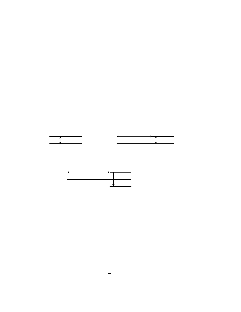
The 20-H rule [1][3] states that the ground planes are extended beyond the power planes by about 20
times the distance between the planes. Let us consider the simple structure consisting of one power plane
and one ground plane shown in Figure 1(a). The 20-H rule structure is shown in Figure 1(b).
Since the radiation is closely related to reflection coefficient at the open end of the two planes, the
reflection coefficient is then investigated. Assume the planes have zero thickness, the reflection coefficient
at the open end of two parallel planes shown in Figure 1(a) can be found in [2]
θ
j
e
R
R
−
=
,
(1)
where
q
e
R
π
−
=
,
(2)
(
)
−
−
−
−
+
−
=
∑
∞
=
+
+
−
1
2
1
2
1
2
1
1
1
sin
2
ln
1
2
m
m
m
m
q
S
A
q
q
q
C
q
θ
,
(3)
and
λ
d
q
=
,
(4)
power plane
ground plane
d
20 d
(b) 20-H rule
power plane
ground plane
image of power plane
2d
power plane
ground plane
d
(a) two planes are of the same size
20 d
(c) image of the power plane in 20-H rule structure
Figure 1
where C is Euler’s constant, which is 0.577216,
λ
is the wavelength and d is the plane separation.
1
2
+
m
A
is
the expansion coefficient of the function
x
1
sin
−
,
∑
∞
=
+
+
−
=
0
1
2
1
2
1
sin
m
m
m
x
A
x
. (5)
1
2
+
m
S
can be obtained by
∑
∞
=
+
+
=
1
1
2
1
2
1
n
m
m
n
S
.
(6)
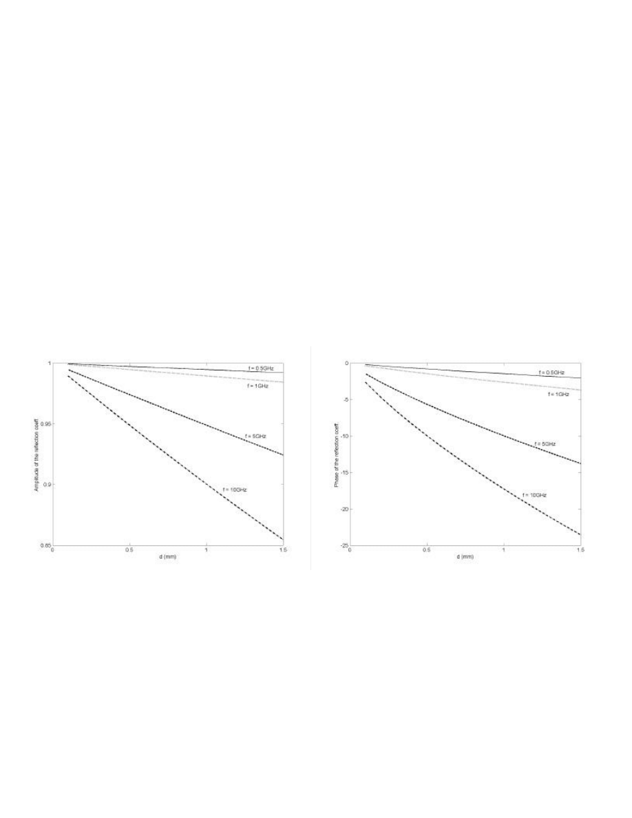
The amplitude and phase of the reflection coefficient as functions of the plane separation d are shown in
Figure 2(a) and 2(b) respectively. It can be seen that the larger the separation between planes, the smaller
the amplitude of the reflections coefficient and the larger the radiation. The reflection coefficient of the
20-H rule structure can be estimated by that of the power plane and its image pair as shown in Figure 1(c).
Because the separation between the power plane and its image plane is twice as large as that of the
structure shown in Figure 1(a), the reflection coefficient of the 20-H rule structure is smaller in the
amplitude. Therefore, more radiation is expected to come out of the edges of the board implemented with
20-H rule.
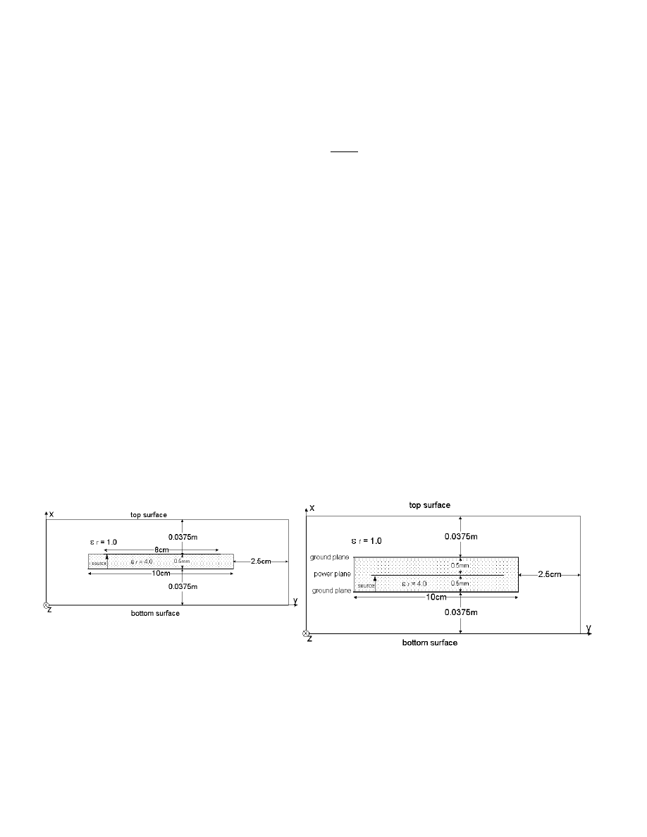
The test structure for the numerical computation is shown in Figure 3. The size of the ground plane is
10cm by 10cm and the plane separation is 0.5mm. The relative dielectric constant is 4.0. The power plane
of the 20-H rule structure is 1cm smaller than the ground plane on each side. 3-D FDTD method is used to
compute the radiation. The radiation power is defined as the surface integration of the poynting vector
( )
(
)
∫
⋅
×
=
Surface
Enclosed
s
d
H
E
t
P
v
v
v
,
(7)
where
E
v
is the electric field and
H
v
is the magnetic field, on an enclosed surface of the board structure.
The radiation is compared between the 20-H rule structure and the normal structure where the ground
plane and the power plane are both of 10cm x 10cm. Figure 4(a) shows the radiation on the top and the
bottom surfaces. The radiation of the 20-H rule structure is somewhat smaller on the bottom surface but
increases significantly on the top surface. The total radiation on the enclosed surface is shown in Figure
4(b), from which one can see the radiation from the 20-H rule board is much stronger than that from the
board of the same size planes. This observation is consistent with the theoretical analysis presented above.
Consider the case where the 20-H rule is applied to the three-plane structure shown in Figure 5. The
top and bottom ground planes are of the same size. The power plane at the middle is shrinked inside by the
“20-H rule”. Radiation is examined on the enclosed surface. Figure 6(a) and (b) compare the radiation of
the normal structure and the 20-H rule structure on the top and the bottom surfaces. It is found that for the
more than two plane structure, there is no significant change in radiation if the power plane in the middle
is setback using 20-H rule.
Figure 3 two-plane test structure
Figure 5 three-plane test structure
Effects of Shielding Vias
The effects of shielding vias are also studied using FDTD method. Shielding vias are added to connect
the two ground planes on four edges of the three-plane structure shown in Figure 5. The radiation from the
board with different numbers of shielding vias is compared in Figure 7. It can be seen that a small number
of shielding vias can cut the radiation significantly.
Conclusion
This paper investigates the effects of 20-H rule and shielding vias on the radiation from the printed
circuit board. For the two-plane structure, 20-H rule yields much more radiation than the normal structure.
For the multiple plane case, no significant change in radiation is found if the 20-H rule is applied to the
internal planes. Also the numerical result shows that the usage of shielding vias would cut down the
radiation effectively.
Reference
[1] Mark I. Montrose, Printed Circuit Board Design Techniques for EMC Compliance, New York: IEEE Inc., 1996.
[2] I. A. Weinstein, The Theory of Diffraction and the Factorization Method (Generalized Wiener-Hopf Technique),
Boulder: Golem Press, 1969.
[3] Dr. Zorica Pantic-Tanner & Franz Gisin, Radiation from Edge Effects in Printed Circuit Boards (PCBs),
presentation at the monthly chapter meeting of Santa Clara Valley Chapter of IEEE EMC Society, May, 2000.
Figure 2. Reflection coefficient at the open end of two parallel planes (a) amplitude (b) phase
(a)
(b)
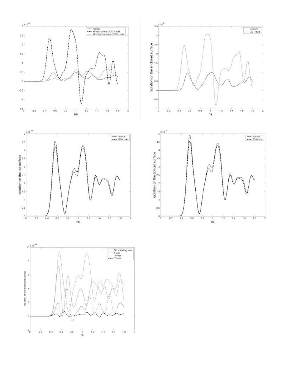
Figure 4. Comparison of the radiation of two-plane structure on (a) top and bottom surface (b) summation of all the surfaces
Figure 6. Comparison of the radiation of three-plane structure on (a) top surface (b) bottom surface
(a)
(b)
(a)
(b)
Figure 7. Radiation from the board with shielding vias

Wyszukiwarka
Podobne podstrony:
Overview Of Gsm, Gprs, And Umts Nieznany
Ecological effects of soil compaction and initial recovery dynamics a preliminary study
Network Virus Propagation Model Based on Effects of Removing Time and User Vigilance
Ebsco Cabbil The Effects of Social Context and Expressive Writing on Pain Related Catastrophizing
You Feel Sad Emotion Understanding Mediates Effects of Verbal Ability and Mother Child Mutuality on
Divergent effects of chaperone overexpression and ethanol supplementation on IBs formation
Effect of Drying Techniques and Storage on Mulberry (Morus alba) Quality
knowledge transfer in intraorganizational networks effects of network position and absortive capacit
the effect of sowing date and growth stage on the essential oil composition of three types of parsle
Junco, Merson The Effect of Gender, Ethnicity, and Income on College Students’ Use of Communication
Sailing Yacht Performance The Effects of Heel Angle and Leeway Angle on Resistance
Effect of long chain branching Nieznany
53 755 765 Effect of Microstructural Homogenity on Mechanical and Thermal Fatique
31 411 423 Effect of EAF and ESR Technologies on the Yield of Alloying Elements
21 269 287 Effect of Niobium and Vanadium as an Alloying Elements in Tool Steels
Effects of the Great?pression on the U S and the World
4 effects of honed cylinder art Nieznany
Effect of Active Muscle Forces Nieznany
więcej podobnych podstron