
Oil Companies International Marine Forum
Effective Mooring
1989

FOREWORD
This booklet is derived from one entitled "Effective Mooring"
which was originally published by Shell International Marine in
1976. The aim of the Shell booklet was to complement technical
publications and rules and regulations with a publication that was
deliberately written in such a style as to communicate effectively
with seafarers at all levels. Experience over the past ten years has
shown that "Effective Mooring" was successful in putting across
its message and therefore the same general format is retained in
this version of the booklet.
The emphasis in this booklet is on SAFETY. Its intention is that
shipboard staff be made more aware of the hazards associated
with mooring equipment and mooring operations by having a
better understanding of the subject. A summary of the personal
safety items mentioned in the text is given in Chapter 7.
This booklet is designed to be self-contained; however, readers
who are interested in obtaining more detailed technical
information should refer to other OCIMF documents dealing with
mooring.
Although this booklet has been written primarily with oil and gas
tankers in mind, most of its contents apply equally to other types
of vessel.
iii

EQUIVALENTS
Many quantities given in this booklet can be expressed in alternative units; the following
approximate conversion factors will be found useful when evaluating equivalents.
To convert
to
multiply by
Metric Tons or Tonnes
Long Tons
0.984
(35 tonnes = 34'/
2
tons)
Long Tons
Tonnes .
1.016
(1000 tons = 1016 tonnes)
Millimetres Inches
0.039
(44 mm = 1 % in)
Inches Millimetres
25.4
(
3
/4 in = 19 mm)
Metres Feet
3.281
(27
1
/
2
m = 1 shackle or 'shot' = 90 ft = 15 fathoms)
Feet Metres
0.305
(12 ft = 3V
2
m)
Millimetres diameter
Inches circumference
0.125
(48 mm diameter = 6 in circumference)
Inches circumference
Millimetres diameter
7.939
(9 in circumference = 72 mm diameter)
Kilogrammes/millimetres
2
Tons/inches
2
0.635
(145 kg/mm
2
= 92 ton/in
2
)
Tons/inches
2
Kilogrammes/millimetres
2
1.575
(11 5 ton/in
2
= 180 kg/mm
2
)
iv

Chapter 1 Effective Mooring
Page
What Does a Mooring System Do?
1
How Big Are These Forces?
1
Mooring Layout
3
Wires or Synthetic Fibre Ropes
4
Elasticity 6
First Line Ashore
7
Vertical Angle (Dip)
7
Mixed Mooring
7
Nylon Tails
7
Chapter 2 Mooring Winches
Render and Heave
9
Winch Brakes
11
Correct Layering •
11
Non Split Drum Winches
11
Split Drum Winches
12
Correct Reeling
13
Brake Condition
14
Testing Brakes
14
Application of Brake
14
Incorrect Use of Brake
15
Brake Holding Capacity
15
Exceptional Circumstances
15
Winch In Gear
15
Freezing Weather
16
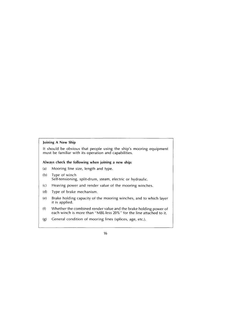
Joining a New Ship
16
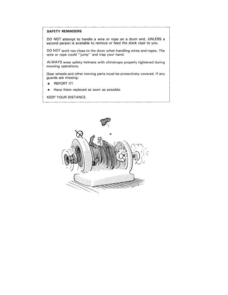
Safety Reminders
17
Chapter 3 Steel Wire Ropes
Construction of Wire Ropes
19
Maintenance of Steel Wire Moorings
23
Selection of Anchor Point for 1st Layer of Wire on a Drum
24
Stoppers for use with Steel Wires
24
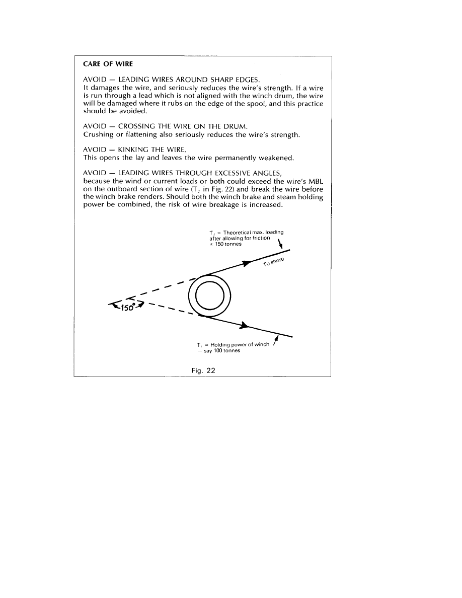
Care of Wire
26
Splicing Wire
27
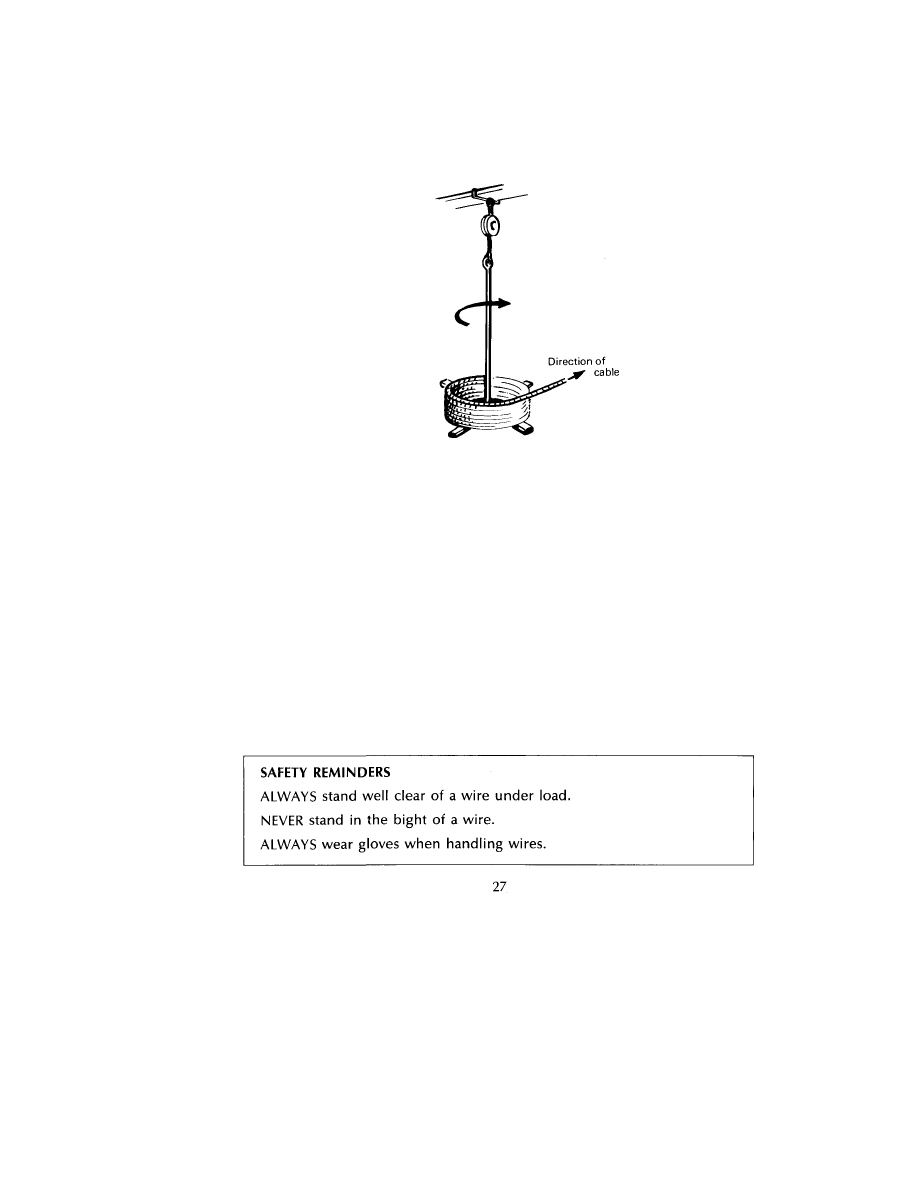
Safety Reminders
27
v

Chapter 4 Synthetic Fibre Ropes
Use of Synthetic Fibre Ropes
29
Types of Materials Used
30
Rope Care
32
Rope Stoppers
33
Splicing
34
Snapback 34
Safety Reminders
36
Chapter 5 Mooring at Buoys
Conventional or Multibuoy Moorings (CBM or MBM)
37
Single Buoy Moorings (SBM)
39
Chapter 6 Windlasses and Anchoring
Brakes
43
Cable Stoppers
43
Anchor Cables
44
Communication 44
Maintenance of Windlass Brakes
45
Adjustments 45
Prolonged Periods of Non-Use
45
Safety Reminders
46
Chapter 7 Personal Safety
Handling of Moorings
47
Safe Handling of Tug Lines
48
Gloves
49
Safety Reminders
50
vi

Chapter 1
EFFECTIVE MOORING
What Does a Mooring System Do?
A mooring system prevents the ship from drifting away from a berth and holds
the ship in place in relation to the loading/discharging arms, which may only
have limited freedom of movement. Mooring lines may also assist in heaving
the ship alongside a berth and can be used to assist in unberthing.
The mooring system has to maintain the ship's position against forces that will
be trying to move it, which may be caused by one or more of the following:
(a) Wind
(b) Current
(c) Surge due to passing ships
(d) Waves and Swell
(e) Change of freeboard
How Big Are These Forces?
At a well sited berth, the greatest forces arise from wind and current, but to
design a mooring system capable of resisting the extreme conditions of wind
and current would create problems in both size and cost of equipment. It is
therefore normal practice to establish arbitrary wind and current criteria and
then design the mooring system to meet these criteria.
Commonly used criteria are:
Wind 60 knots, plus a current on the beam of 0.75 knots, or
Wind 60 knots, plus a current from ahead or astern of 3 knots.
Both wind and current forces are proportional to the square of the wind or
current speed, thus the force caused by a 60 knot wind is four times that caused
by a 30 knot wind, and the force exerted by a 3 knot current is nine times that
exerted by a 1 knot current.
Wind speed increases with height above sea level. For example, a wind of
60 knots at 10 metres will be more than 75 knots at 30 metres but only 30 knots
at 2 metres (just above man-high). So that information from different sites can
be compared, it is usual to correct all anemometer readings to an equivalent
height of 10 metres.
Because of the speed/force and speed/height characteristics of wind behaviour,
freeboard is a major and sometimes critical factor for safe mooring.
1
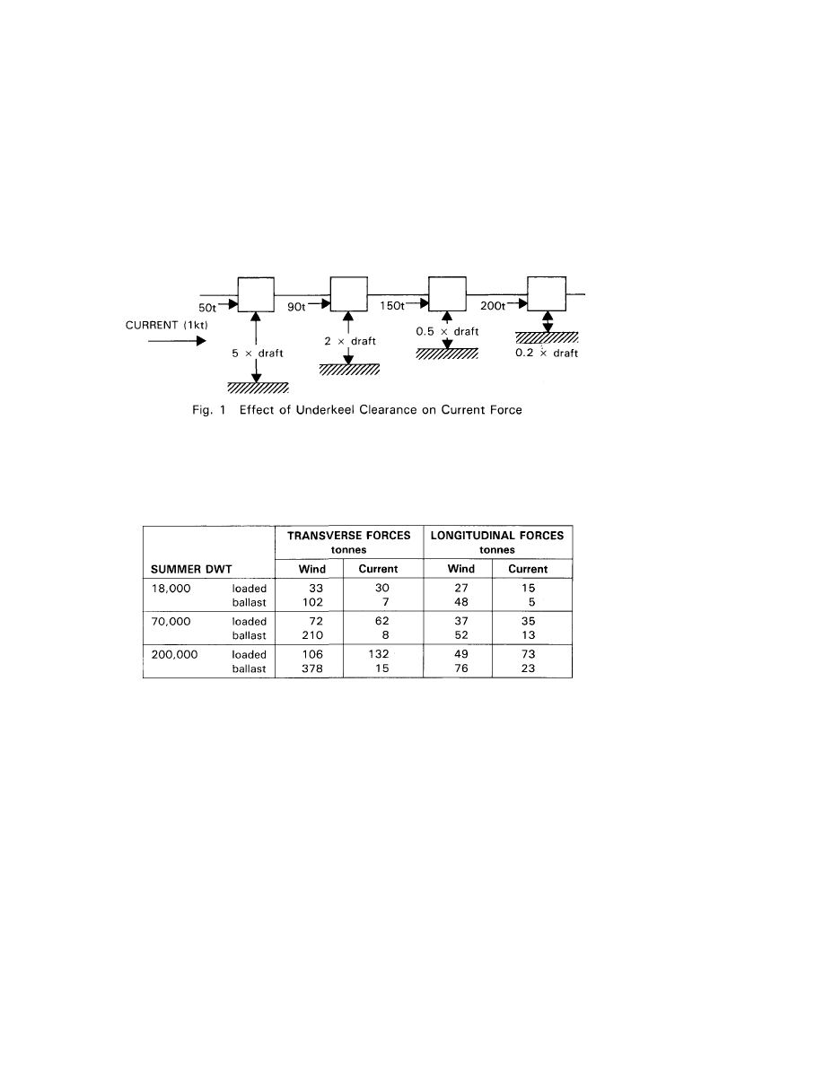
In the case of currents, forces become significant when the clearance under the
keel is small in relation to the draft. In this situation, and when the current is
from the beam, the ship begins to act as a major obstruction to a current which
must either escape around bow and stern or accelerate under the keel. A
similar but less pronounced effect occurs with currents aligned to the ship's
fore and aft axis.
A well designed berth will be sited so that the current will be end on or nearly
end on, but Fig. 1 shows how the current force due to a beam current increases
as the "depth/draft ratio" is reduced.
Ballasting the ship down will usually reduce the total forces acting on a ship
as the wind gradient effect is greater than the underkeel clearance effect.
The table below gives some examples of the forces on various ship sizes due
to wind (60 knots) and current (3 knots ahead or 0.75 knots abeam).
A ship moves vertically up and down alongside a berth both with the tide and
as a result of cargo operations. It is perhaps stating the obvious to see that as
a ship rises, the tensions in the mooring lines will increase. Conversely, as the
height above the jetty decreases, the lines will become slack and the ship is
likely to move away from her proper position. The only reliable remedy for this
is regular line tending whilst the ship is moored at a jetty.
2
Forces caused by passing ships, waves or swell are complex and continually
varying, although at most berths they will not create problems for a ship that
is using her equipment properly. Where these forces are unusually large, jetty
operators will have made some provision to supplement the ship's system.
Attention to mooring restraint is especially important in the case of a deep draft
loaded ship with minimum underkeel clearance berthed close to a shipping
lane, when the force from passing ships could be large enough to part the lines
or pull the ship off the dock if the lines are slack.
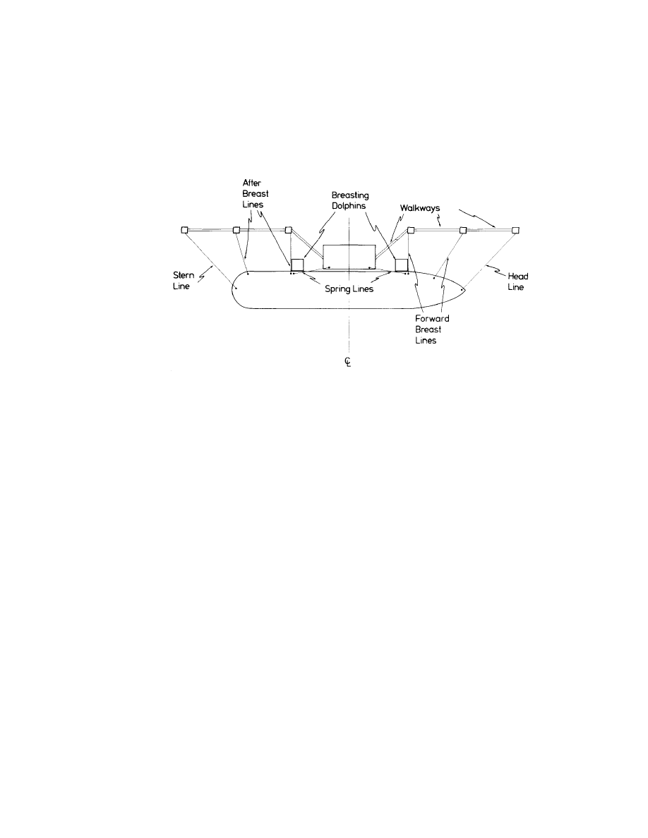
Mooring Layout
Fig. 2 Typical Mooring Arrangement
Whilst it is often difficult in practice to achieve an ideal mooring layout, Fig. 2
shows a typical mooring arrangement designed to resist environmental forces
acting on the ship. These forces, particularly wind, can come from any
direction, but when discussing mooring systems the forces are split into
longitudinal and transverse components. A ship's equipment can always be
employed to the best advantage if the following general principles are
remembered:
(a) Breastlines provide the bulk of the transverse restraint against off-the-
berth forces.
(b) Backsprings provide the largest proportion of the longitudinal restraint. It
should be noted that spring lines provide restraint in two directions,
forward and aft, but that only one set of springs will be stressed at any one
time.
(c) Very short lengths of line should be avoided when possible, as such lines
will take a greater proportion of the total load, when movement of the
ship occurs. Short lines are also the ones most seriously affected by "dip"
[see page 7].
3
Although headlines and sternlines, because of their direction, have the effect
of providing some restraint against both longitudinal and transverse forces,
they actually contribute less to the overall mooring strength than is commonly
supposed. This is because the direction of the largest forces encountered is usually
either nearly transverse or nearly longitudinal, ie along the lines of action of breast
or spring lines respectively.
Additionally, they are almost always much longer than the breastlines and so
take a reduced share of the load. However, where the jetty layout prevents the
use of the forward and aft lines as breast or spring lines only, the contribution
of headlines and sternlines to the overall security should not be ignored.
The most extreme conditions, ie light ship and combined beam wind and
current, will usualy produce a resultant force vector within about 25 degrees
of the beam.
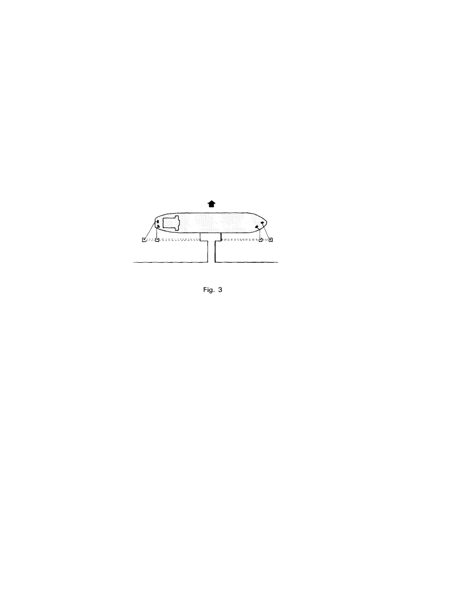
Transverse force
In the example illustrated in Fig. 3, with the headlines leading at 45 degrees to
the breastlines, the contribution of the headlines to the total transverse
restraint is only about 26% of the whole. Even if the total resultant force aligns
with a headline, the line takes only 41% of the load, with the breastline and
springline sharing the remaining 59%.
Wires or Synthetic Fibre Ropes
The key factors for any wire or rope are strength, which is usually described
by reference to minimum breaking load, and elasticity, which is a measure of
its stretch under load.
Synthetic fibre ropes are adequately strong and of a reasonable size for
mooring small to medium sized ships, but for large sized ships the ropes may
become too large to handle unless fitted on self stowing winches. Further, the
handling of a large number of such ropes would be difficult.
4
In addition, most synthetic fibre ropes stretch far more than wires. A typical
figure for the extension of a nylon rope at maximum load is in excess of 30%,
compared with 1
1
/2% for a wire. As the mooring ropes of a VLCC may reach 70
to 100 metres, it is clear that a normal synthetic fibre rope mooring system is
unlikely to provide the accurate positioning demanded by the loading arms.
[Despite the above comments it should be noted that there is a group of
synthetic mooring ropes (the "Aramides" or "Aramid fibre ropes") which have
been developed fairly recently and which have an extension comparable with
that of wire. However, their high cost generally limits them to specialist
applications.]
Whilst smaller ships may be equipped with synthetic fibre lines, it is normal for
larger ships to be equipped with wires fitted to self stowing winches. Even on
smaller ships, wires, if fitted, are normally on self stowing winches for ease and
safety of handling, and on new buildings it is common practice for the synthetic
lines to be fitted to self stowing winches.
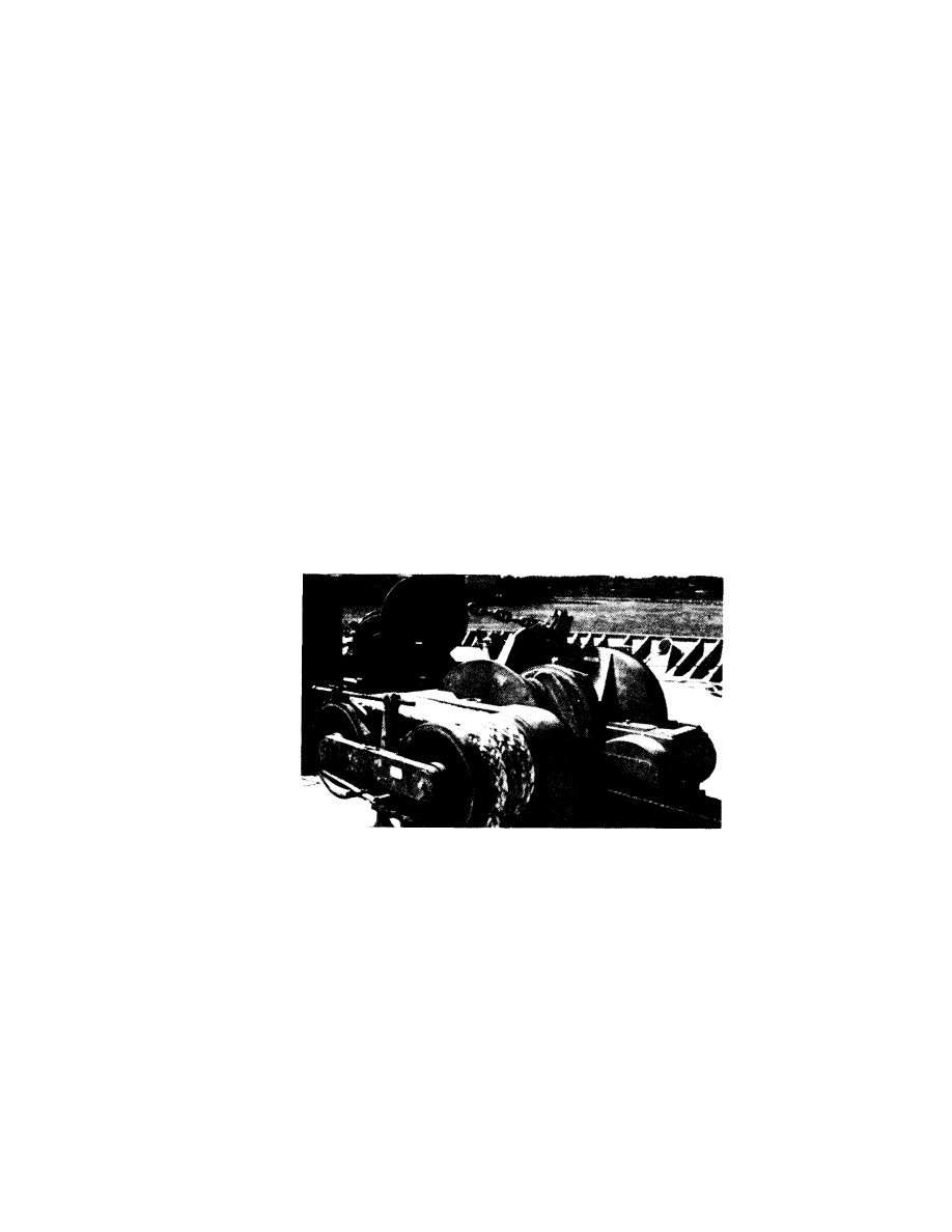
A synthetic fibre rope fitted to a self-stowing winch is sometimes provided at
each end of the ship. Its purpose is to act as the "first line ashore" as its light
weight and buoyancy make for easy handling in a mooring boat, on the jetty
and on board, and it can thus be sent ashore easily when the ship is some
distance from the berth (Fig. 4). It can then be used to assist in heaving the ship
alongside the berth. However, because of its greater elasticity it should not be
considered as part of the actual mooring system unless the other head and
stern lines are of a similar material.
Fig. 4 First Line Ashore Equipment. Split drum assembly in background
5
Elasticity
The elasticity of mooring lines is important because it determines how the total
load will be shared between a number of lines.
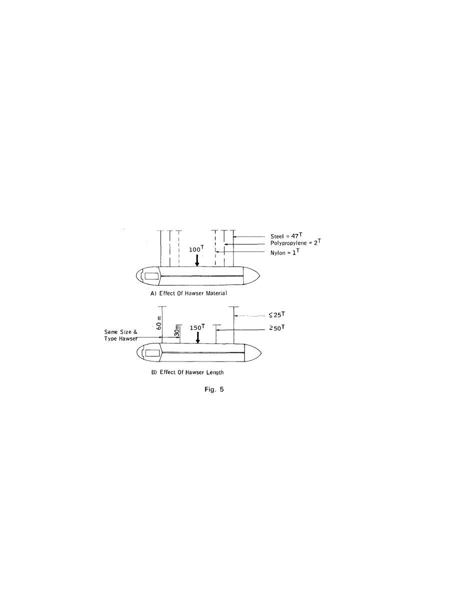
If two lines of the same size and material are run out in the same direction and
pre-tensioned, but one is secured to a hook twice as far away as the other, the
shorter line will take % of any additionally imposed load, the longer one only
1
/
3
.
Therefore, two or more lines leading in the same direction should, as far as
possible, be of the same length.
If two lines are of the same length, the same breaking strength, and have the
same lead, but one is a wire of 1
1
/2% full load elongation and the other is a
synthetic of 30% full load elongation, the wire will take 95% of the extra load,
the synthetic only 5%.
Hence, two or more lines leading in the same direction should always be of the
same material. Never mix wire and soft moorings if you can avoid it.
Fig. 5 demonstrates the significance of material and length of lines.
Elasticity of a given type of line also varies with diameter, with a larger rope
extending less than a smaller rope. Although this is unlikely to be an important
factor, as mooring lines on a ship are usually of a uniform diameter, it should
be borne in mind when ordering new mooring lines.
6
First Line Ashore
Although a synthetic fibre rope will not normally give much help in an all-wire
mooring system owing to its higher elasticity, a "first line ashore" (if carried)
is usually fitted onto a self-stowing winch of some kind. Hence this rope can
be used to supplement the other moorings in an emergency by heaving at its
full capacity. If the other head and stern lines are of similar material, then this
line can be considered as part of the mooring system.
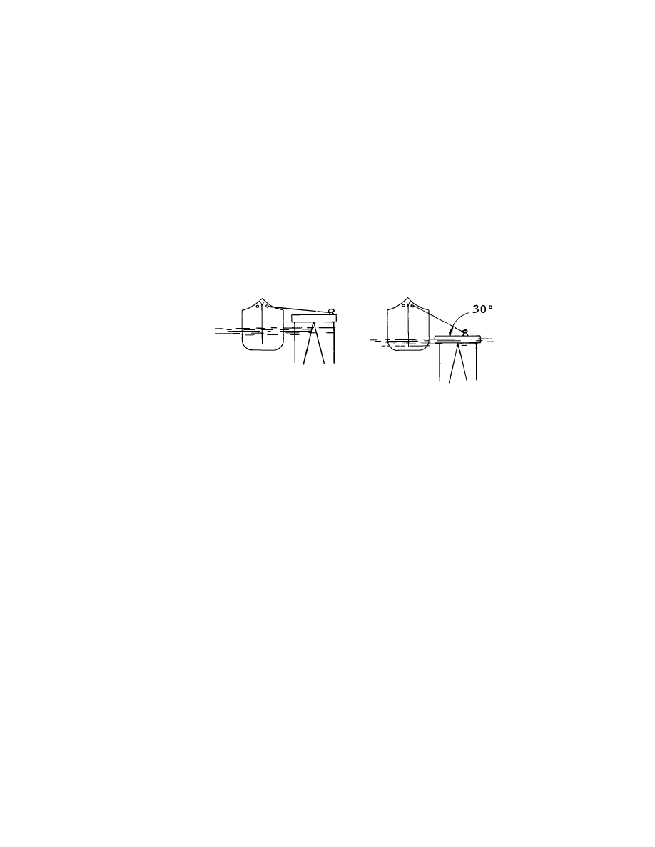
Vertical Angle (Dip)
Whenever a line is unable to act in exactly the same direction as the force it
is trying to withstand, its holding power is reduced. Hence a short line to a
mooring hook substantially lower than the ship's fairlead will be of limited
value. The effectiveness is proportional to the cosine of the angle the line
makes to the horizontal, ie for 30 degrees the line is 87% effective and, for
45 degrees, 71% effective (Fig. 6).
Fig. 6
Mixed Moorings
Not every ship is fortunate enough to possess an all-wire or all-synthetic
mooring outfit and in such cases the best must be made of a mixture of wires
and synthetic fibre ropes.
The earlier discussion indicated that the best procedure is to use, wherever
possible, the wires for the spring and breast lines. The synthetic ropes are best
reserved for headlines and stern lines, and for heaving alongside the berth.
Nylon Tails
Although wire moorings provide the most effective mooring system by reason
of their low elasticity, that same low elasticity can also pose its own problem,
particularly at berths where sea and swell, or perhaps passing ships, could
impart shock (dynamic) loadings to the mooring system. In such cases there
may be insufficient elasticity to prevent failure of the mooring wires.
7
This problem can be overcome by introducing a degree of elasticity by
attaching nylon tails to the end of the wires and these are attached by means
of a special joining shackle designed to minimise wear on the wire. The use of
an ordinary "D" or "bow" shackle should be avoided as this will quickly
damage both wire and tail.
Fig. 7 Stainless Steel Shackles for Lines with Tails
In order to keep the additional elasticity to the minimum required to prevent
wire failure, the length of the tail should not exceed 11m, and because nylon
tails are likely to deteriorate more rapidly than wire, they should be at least 25%
stronger than the wires to which they are attached and should be inspected
frequently or replaced at regular intervals. The eyes of the tails should be
covered in leather or plastic sheathing to protect them from chafing.
When tails are used, the shackle may cause increased wear on the eye of the
wire, and this area should be inspected at regular intervals.
'a heaving system of some kind'
8
Chapter 2
MOORING WINCHES
Mooring winches can be driven by steam, electric or hydraulic motors.
Although steam is very common, many newer vessels are fitted with hydraulic
equipment; electric winches are not common on board tankers.
Render and Heave
Whatever the power source, all mooring winches will be affected to a greater
or lesser degree by a characteristic known as "Render/Heave Ratio". The term
"Render" is defined as the force required to turn the winch in the opposite
direction when set to heave with the driving force applied.
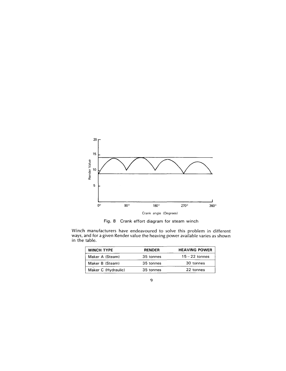
With hydraulic and electric driven winches, the render value is constant but
with steam winches the render value varies. This is because the torque available
is dependent upon the position of the pistons. Fig. 8 is typical of a two-cylinder
machine.
As can be seen, the Render/Heave ratio can vary between 1.17 and 2.3 because
of the differing mechanical advantages of different winches. It should be noted
that the heaving power is always less than the render force and it is thus impossible
to heave in after a winch has rendered unless there is a change in the forces acting
on the moorings.
Many ships are equipped with self-tensioning winches with the intention of
eliminating the need for line tending. These are designed so that a specified
line tension can be pre-set, and the winch will render (pay out) when tension
in the line exceeds this value, and will recover (heave in) when it is less than
this value.
However, experience has shown that the use of such winches whilst the ship
is alongside is not a safe practice because the winch restraint is limited to its
render load, which is small compared to what it can hold on the brake. It is
possible for the winches at opposite ends of the ship to work against each other
when an external force caused by either wind or current or both is applied to
one end so that the ship could "walk" along the jetty. In the simple illustration
given by Fig. 9 a ship is shown moored by one line at each end.
Fig. 9
Should the bow winch render a little for any reason (ie, a change in direction
or force of wind or current) some wire will pay out, which cannot be heaved
onto the drum again because the heaving force of a winch is always less than its
render force and it is not possible to heave in until the external force which
caused it to render is reduced. Consequently, the ship drifts astern a little and
the after mooring begins to slack. The aft winch then heaves in that slack and
re-tensions the line. If the disturbance is repeated or continuous the ship will
move progressively astern.
Mooring winches should not therefore be left in automatic self-tensioning mode
once the ship is secured alongside. On completion of mooring the winch should be
left with the brake on and out of gear.
10
Winch brakes
The holding power of winch brakes varies from ship to ship, but will always be
designed to exceed the "render" value of the winch.
The above statement is dependent upon several factors which are discussed
below.
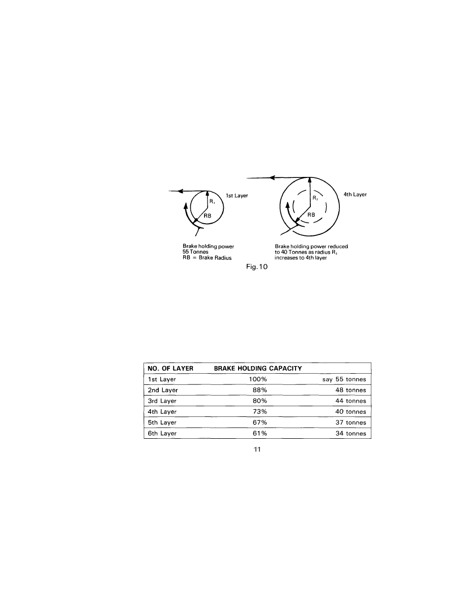
Correct Layering
The number of layers of line on the drum effects the brake holding power.
The force at which the brake will slip will vary, dependent upon the number
of layers of wire left on the drum, and the more layers of wire on the drum the
greater will be the reduction of brake holding power. This is illustrated in
Fig. 10.
Non Split Drum Winches
The brake holding capacity for these winches (non split drum) will always be
quoted for a specific number of layers. In order to minimise any reduction in
brake holding power, the line should always be reeled on to the drum in a
symmetrical pattern and not allowed to pile up on one side or in the centre.
However, due to the length of line involved, it may not always be possible to
achieve this in practice.
The following table shows a typical loss of brake holding capacity for each
layer, based on 100% on the first layer:
Where possible, check for brake holding values by referring to manufacturer's
literature or ship's plans. If the brake holding capacity is known, but the layer
to which it is applied is not, for the sake of safety assume it applies to the
1st layer and make allowances accordingly.
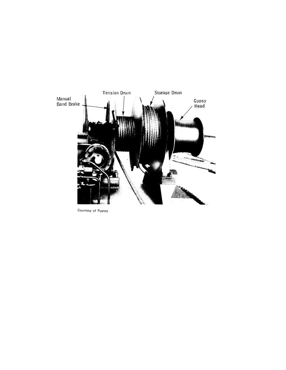
Split Drum Winches
This design minimises crushing damage and is normally only used with wires.
The brake holding capacity for these winches (Fig. 11) is always quoted for only
a single layer of wire on the tension drum.
Fig. 11 Typical split-drum winch
When using this equipment, difficulty may be experienced when:
(a) Manhandling the wire from the storage drum to the tension drum.
(b) Judging the correct length of wire so that only one layer of wire is present
on the tension drum all the time the ship is alongside.
12
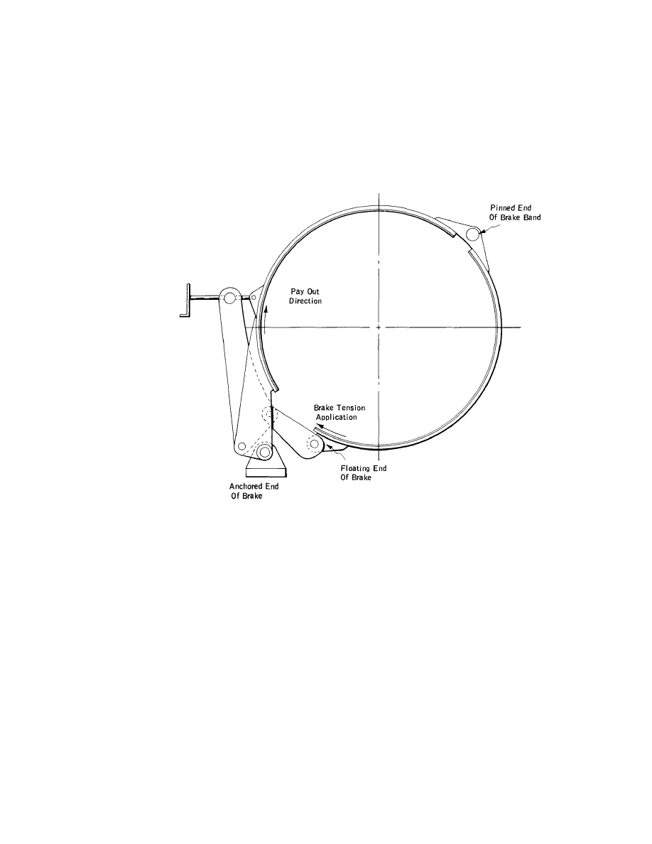
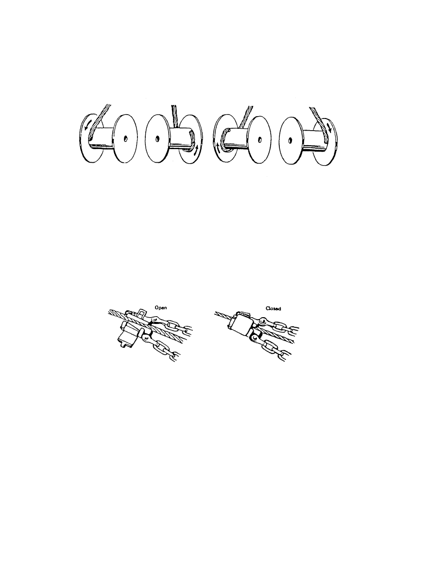
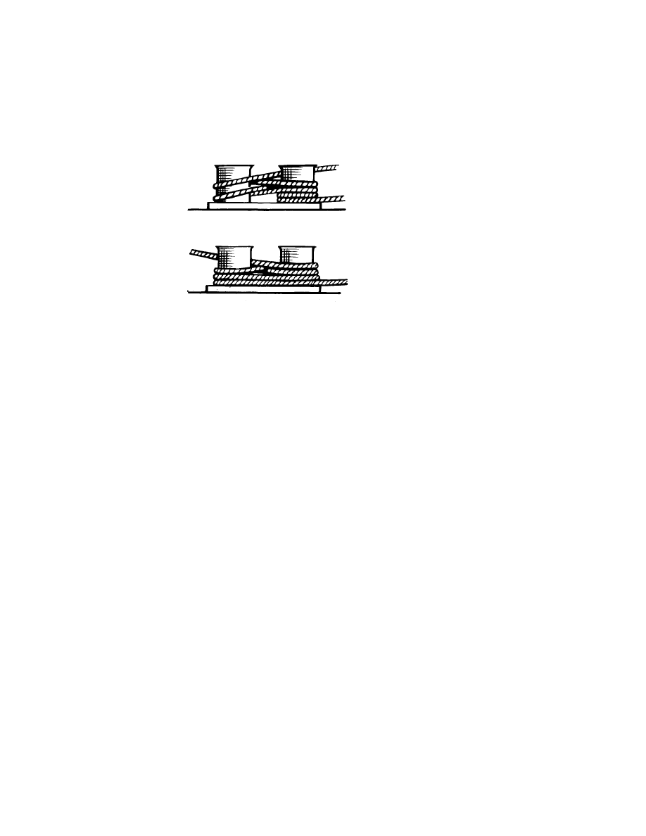
Correct Reeling
The line must be reeled on to the winch drum in the right direction and
manner.
Band brakes are designed for the line to pull directly against the fixed end of
the brake band. Fig. 12 shows the correct method of reeling.
Fig. 12 Reeling of Wire on Winch Drum
Reeling the line on to the drum in the wrong direction may reduce the brake
holding power by up to 50%. Winch drums should be marked to indicate the
correct reeling direction.
Winches fitted with disc brakes are not subject to this problem.
13

Brake Condition
The physical condition of the winch brakes effects the holding power.
Oil, moisture or heavy rust on the brake linings or drum can seriously reduce
the brake holding power, in extreme cases by up to 75%.
Moisture can be removed by running the winch with the brake applied very
lightly, although care must be taken not to cause excessive wear. Oil
impregnation cannot be removed so linings should, if so affected, be replaced.
Whenever brakes are opened up for any reason, the brake drum should be
examined for build-up of rust or worn brake material and should be descaled
as necessary.
Brake linkages must be free and greased. If the linkages are not free there will
be a loss of brake holding power and the winch operator could be under the
impression that the brake is fully applied when in fact it may not be. Severe
stresses could also be imposed on mechanical parts of the brake.
Before the end of a sea passage, when the brakes will have been exposed to
the air and sea, it is essential to check them and ensure that all control and
operating handles are oiled or greased and are free and easy to use, that all
linkages are greased, and that the brake drums and linings are clean and (so
far as possible) dry.
Testing Brakes
Deterioration of the brake holding capacity will be caused by normal wear
down of the brake linings. Brake holding capacity should therefore be tested
annually or after excessive loading has been experienced. Brake linings should
be renewed if there is any significant deterioration of holding power.
Application of Brake
When there is a load on the line, the fact that the brake is not fully applied will
be all too obvious. However, it is sometimes difficult to tighten manually
applied brakes to their maximum possible extent when there is little load on
the line. Different people are of different builds and can apply different forces
to the brake applicator.
Therefore, when the freeboard is increasing during cargo discharge or with a
rising tide, brakes should be tightened at frequent intervals even if there is no
sign of slipping. As the load in the line increases, redistribution of stresses in
the brake band will often relax the load on the applicator, allowing the brake
to be tightened further.
Ships with hydraulic brakes will probably have a torque indicator which shows
the actual torque applied to the brake, and this should always be maintained
at the level designated by the winch manufacturer.
14

Incorrect Use of Brake
The brake is a static device for holding a line tight and it is not intended as a
means for controlling a line. If a line has to be slacked down, the winch should
be put into gear, the brake opened and the line walked back under power. It
should never be slacked down by releasing the brake as this causes increased
and uneven wear on the brake band, it is uncontrolled and thus unsafe, and
if two lines in the same direction have equal loads then the entire load will be
suddenly transferred to the other line, which may then part.
Brake Holding Capacity
The value of the brake holding capacity in relation to the size of line is
important; there would be little point in a mooring system where the line parts
at a load less than the brake holding acpacity. Brakes should have a holding
capacity of about 60% of the breaking load of the wire, which will permit slippage
before the wire breaks.
This factor should be considered when renewing lines and reference should be
made to the ship's specification or appropriate drawings.
It should be remembered that the brake holding power is always greater than the
heaving power, and that once the brake starts to slip (render) it is impossible to
heave in unless the forces causing the slippage are reduced.
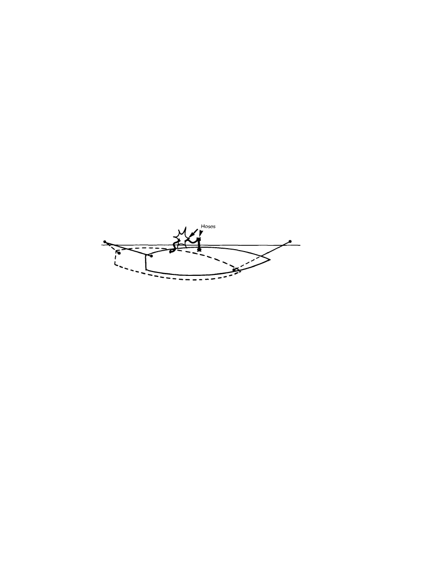
Exceptional Circumstances
Occasionally, unanticipated changes of load, perhaps caused by extreme
winds, waves, swell or tide, may cause the brakes to slip and the ship to be at
risk of moving off the berth. Should this occur, do NOT release the brakes and
attempt to heave the ship alongside, as this is impossible (see above), and any
attempt to do this will only worsen the situation. Tug assistance should be
requested, the engine should be made ready for manoeuvring, and hoses
should be disconnected.
If the problem is caused by high winds, consideration should be given to
reducing the freeboard by the addition of extra ballast if this is possible.
Winch In Gear
The brake holding capacity can be increased by leaving the winch in gear with
the power on and set to "heave". However, this should only be considered in
an emergency situation and should not be carried out in normal operations as
it is possible to:
(a) exceed the breaking strain of the line and the safe working load of leads
and rollers,
(b) damage the winch by distorting the shaft.
15
As an example, if the render value is 35 tonnes and the brake holding power
is 65 tonnes, the total holding power is 100 tonnes. If a line with a new braking
load of 108 tonnes is used, and allowing a 20% reduction for wear and tear, then
the breaking load is only 86 tonnes, and the line will probably part.
It is also ineffective where one winch drives two or more drums as it is not
normally possible to engage all the drum shafts whilst at the same time main-
taining equal tension on the lines.
Thus, this practice should only be considered in an emergency situation.
Freezing Weather
During periods of freezing weather, it may be necessary to run the steam
winches continuously to prevent serious damage to the cylinders, steam pipes,
etc. Alternatively, some winches are provided with a steam-to-exhaust by-pass
valve which can be adjusted to allow sufficient steam to pass through the
system to prevent the pipes freezing up.
On certain winches, when the brake is applied and the drum is out of gear, the
winch motor still drives the drum shaft. If the wire is under load, this load is
transferred to the drum bearings and the rotating shaft, resulting in eventual
wear of the bearings. Where this is the case, it is preferable to utilise the steam
and exhaust by-pass valves to prevent damage in cold weather.
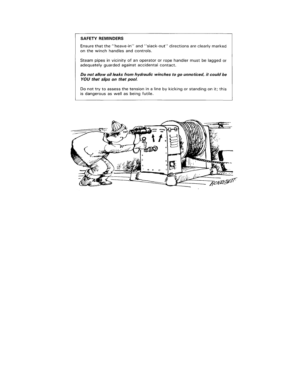
'... ensure controls are clearly marked'.
17
Chapter 3
STEEL WIRE ROPES
Construction of Wire Ropes
When a high Minimum Breaking Load (MBL) together with reasonable ease of
handling is required, it is usual to select wire ropes.
A wire rope consists of a number of strands layed up around a central core of
fibre or wire. Each strand in turn consists of a number of wires layed up to form
the strand.
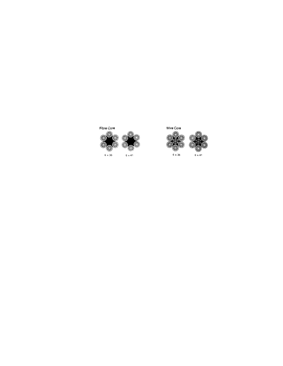
It is normal to describe the rope in terms of the number of strands and number
of wires per strand, eg. 6 x 36, 6 x 41 (Fig. 13).
Fig. 13
The first number is the number of strands in the rope and six round strands
around a central wire or fibre core are the normal construction for marine use.
(Ropes of eight strands, or multiple strand design, or triangular strand design are
also available but are normally restricted to specialist applications.) The second
number is the wires in each strand; ropes with more wires have greater flexibility
and fatigue resistance but have less resistance to abrasion, whilst those with
fewer wires have less flexibility and fatigue resistance but more resistance to
abrasion. A standard mooring wire is of 6 x 36 or 6 x 41 construction.
Several constructions are available and the following definitions and
illustrations will be of assistance in identifying the different wire types:
Definitions
Lay — the twisting of strands to form a rope, or wires to form a strand, during
its manufacture.
Righthand or Lefthand Lay — the angle or direction of the strands relative to the
centre of a rope.
19
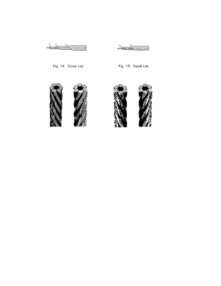
Fig. 16 Ordinary Lay
Fig. 17 Lang's Lay
Ordinary Lay (Fig. 16) — a method of making a rope where the lay of the wires
in the strand is opposite to the lay of the strands in the rope.
Lang's Lay (Fig. 17) — a method of making a rope where the lay of the wires in
the strand is the same as the lay of the strands in the rope. Although this
construction has better wearing properties than ordinary lay, because it tends
to untwist it has only limited use. It is not used for mooring lines.
Aggregate Breaking Load — the sum of the breaking loads of all the individual
wires used to form a wire rope.
Minimum Breaking Load (MBL) — the smallest load at which a wire rope breaks
when tested to destruction. This value is usually the manufacturer's guaranteed
breaking load and is the figure that should be quoted when ordering wires.
20
Cross Lay (Fig. 14) and Equal Lay (Fig. 15) — terms describing the lay of the wires
used to make up the strands.

Spinning Loss — due to deformation of individual wire strands during
manufacture, the actual breaking load of a wire rope is always less than the
aggregate breaking load. The difference is referred to as Spinning Loss.
Yield Point — the point at which the ratio of strain/stress increases sharply. This
is the point at which a wire may become permanently distorted.
Equal Lay construction gives superior performance over a Cross Lay rope of the
same diameter because:
(a) It possesses up to 14% higher MBL due to lower spinning loss. This is
because all the layers of wire have the same pitch or length of lay, and
each wire in each layer lies either in the trough between the wires of the
underlayer or alternatively along the crown of the underlying wire.
(b) No wire crosses over the crown of the underlying wires as in Cross Lay
construction, thus reducing internal wear by the elimination of cross
cutting.
A standard 6-strand Equal Lay/Ordinary Lay construction is usually adopted for
mooring wires, and wires of diameter 22-40 mm are usually 6 x 36 construc-
tion, and larger wires 6 x 41. Mooring wires are usually Righthand Lay unless
otherwise specified.
Wire ropes can be supplied in different grades of steel, usually 145 kg/mm
2
or
180 kg/mm
2
. The latter is recommended because, for a given diameter of wire
rope, an increased MBL and general better performance is obtained.
Wire ropes can be supplied in Righthand Lay or Lefthand Lay. Unless otherwise
specified, a Righthand Lay will normally be supplied.
Wire ropes can be supplied with fibre cores or steel wire cores. Fibre cores will
give easier handling and are ideal for use with smaller wire sizes and where a
wire is to be handled manually and say "turned up" on bitts or bollards.
Where the wire ropes are used on storage drum type winches with little manual
handling, it is advantageous to use a steel wire core. Wires constructed using
a steel wire core offer a greater resistance to the crushing forces experienced
on these winches, suffer a smaller loss of MBL when bent, are about 7-8%
stronger and extend slightly less (
1
/4-
1
/2% as opposed to
1
/2-%%) than a fibre
core wire rope of the same diameter (Fig. 18 refers).
Mooring wires are usually galvanised in order to provide better resistance to
corrosion.
21
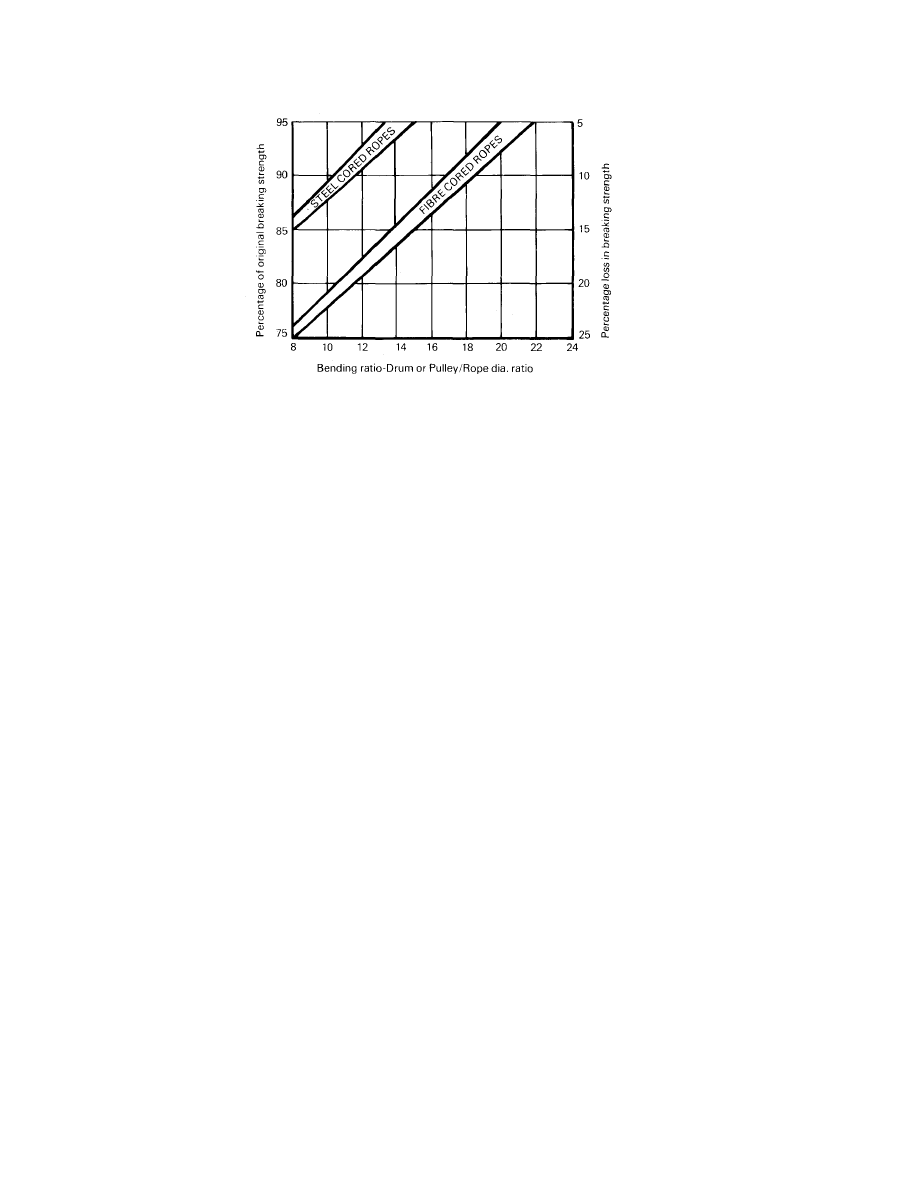
Fig. 18 Graph showing the loss in breaking load when
a wire is bent over small diameters
To summarise, the wires most frequently found on self-storing winches will be
of the following constructions:
(a) Equal Lay
(b) Ordinary Lay
(c) Righthand Lay
(d) Steel wire Core
(e) Usually of engineering grade steel, ie 180 kg/mm
2
(f) 6 x 36 or 6 x 41
Wire rope is used in preference to synthetic fibre ropes because it possesses:
(a) Low elasticity, ie. limited stretch. When a wire is first used under load
there is a slight permanent extension known as "constructional" stretch
which results from a slight rearrangement of the wires. After this the wire
experiences an elastic stretch which is recoverable and linear up to about
65% MBL; above this the stretch increases non-linearly until the line
breaks.,
(b) A strength/diameter ratio superior to most synthetic fibre ropes (apart
from Aramid fibres and other specialist ropes).
(c) A smaller diameter making it suitable for use on storage reels that can be
directly linked to the winch. (The maximum diameter found in normal
service is usually 44mm.)
22
When delivered, all mooring wires should be accompanied by a certificate from
the manufacturer indicating the minimum breaking load. These certificates
should always be consulted if it is necessary to ascertain the specification of a
particular wire.
Maintenance of Steel Wire Moorings
It is essential to grease or oil steel wire mooring ropes at frequent intervals as
rusting will reduce the strength of the wire in a very short time.
It is important that periodically the whole wire is physically removed from the
drum for inspection and greasing.
Investigations have shown that deterioration of the wires can occur undetected
on the bottom layers, especially when a wire has seen some service and has
been turned "end for end".
Regular visual inspection is vital, particularly around eyes which are shackled
to nylon tails, as the shackle tends to increase wear on the wire at this point
(see p 8).
If "dry" or darkened patches are observed, the depth and degree of corrosion
should be checked. An effective way to do this is to place the wire on a solid
surface and strike it with a hammer. This will cause the rust to fall away and
will part the weakened strands, exposing the severity of the corrosion.
Snags in a wire also indicate a reduction in the strength.
Wires must be replaced if the number of broken strands (snags) exceed 10%
of the visible strands in any length of wire equal to 8 diameters.
23
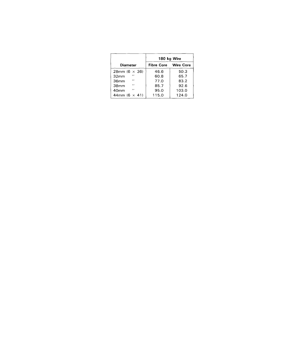
The table below shows some typical breaking loads (in tonnes) for round strand
equal lay wire ropes:
Selection of Anchor Point for 1st layer of Wire on a Drum
When fitting a new wire to a mooring winch, or replacing an old wire after
inspection and greasing, it is important that the wires are replaced as shown
in Fig. 19.
Wires with Righthand Lay
Wires with Lefthand Lay
Fig. 19
Stoppers for use with Steel Wires
There are two methods of stoppering a steel wire prior to turning it up on the
bitts.
One method is to use a specially designed stopper such as the Carpenter
stopper (Fig. 20). The second and only other recognised method of stoppering
wires is to use a length of chain.
Fig. 20 Carpenter stopper
Rope must never be used as a stopper on wires because it does not grip the
wire well enough.
24
Where a carpenter type stopper is used, it is recommended that the stopper be
of equal breaking load to the wire size for which it is designed. An important
safety feature of this type of stopper is that when in position, it is self-tightening
and can be left unattended. Further, it will not damage the wire when under
load, provided it is of correct size and design for the circumference and lay of
wire rope on which it is to be used.
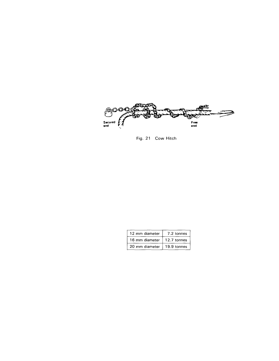
Where carpenter type stoppers are not available, it is important to note the
following:
When securing a chain stopper to a wire, use only a "Cow Hitch" (also known
as a "Lanyard" hitch) (Fig. 21), never a "Clove Hitch".
Stoppers exceeding 20 mm diameter are virtually unmanageable and hence this
is the largest size likely to be encountered. All chain stoppers should be tested
and annealed at each vessel refit.
Warning: In most cases, the stopper will break at a lower load than the wire.
When ordering chain stopper, it is important to specify the following:
Size — Diameter of link.
Type of chain — close link, higher tensile steel, ie. tensile strength in the
o'rder of 63 kg/mm
2
, equivalent to BS1663 Grade 40. (Superior grades and
higher breaking loads are available if required.)
The following table shows typical breaking loads for Grade 40 steel chain.
(Note: The diameter is the diameter of the steel forming the link of the
chain.):
Length of chain — usually 3.5-4.5 m.
25
Always check a wire for snags before use.
The practice of sighting any wire before use could also prevent an injury or
accident.
26
Do not open a new coil of wire without using a turntable or similar apparatus,
in order to avoid kinking the wire.
Fig. 23
Splicing Wire
Modern practice is for mooring wires to be supplied with eyes formed by
means of a ferrule applied mechanically by the manufacturer. If the eye is
damaged, it can be cut off and a new eye spliced in the wire. If this is done
there should be a minimum of 5 full tucks and 2 half tucks. However, a manual
splice will effectively reduce the MBL of the wire by 10-15%, and it is prefer-
able to have the eye re-made by a mechanically applied ferrule. It will be found
that it is extremely difficult to put an effective manual splice in a large mooring
wire.
Short splices should not be used on wires fitted to self stowing winches as the
splice could further deform or damage the wire on the reel.
Chapter 4
SYNTHETIC FIBRE ROPES
Use of Synthetic Fibre Ropes
Synthetic fibre ropes have now almost completely superseded natural fibre
ropes for mooring purposes. As with steel wire ropes, there exist many
relatively new terms and rope types, a few of which are described below.
Mooring ropes are normally made of nylon, polyester, polypropylene, or a
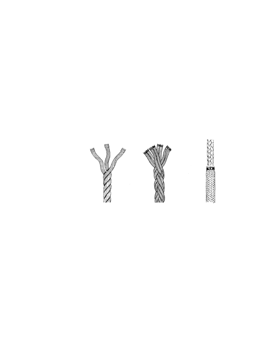
polyester/polypropylene mixture. Although hawser laid ropes (Fig. 24) may still
be found in use, they are not favoured because of their tendency to kink and
their relative stiffness in handling. More common these days are 8-strand
plaited ropes (sometimes called square braid); the balance between left and
right hand strands make them virtually unkinkable and very flexible. Fig. 25
shows an 8-strand plaited rope and Fig. 26 shows a sheathed and plaited
construction known as double braid or braid on braid often used for
specialised purposes (ie. first line ashore equipment), which consists of a
plaited inner rope covered by a tightly plaited sheath which may be of a
different or similar material to the inner rope.
Fig. 24
Fig. 25
Fig. 26
As mentioned in Chapter 1, mooring ropes are available manufactured from
Aramid fibres. These have very low extension under load (approaching that of
wire) and a higher breaking load than other synthetic fibres of the same size.
They are however very expensive and their use is generally limited to special
applications or specific situations.
29

Types of material used
NYLON — this is the strongest of the man-made rope fibres, except for Aramid,
and has exceptional resistance to sustained loading. It is highly resistant to
chemical attack from alkalis, oils and organic solvents, but will be damaged by
acids. However, its high elasticity makes it unsuitable for tanker moorings,
where the ship's movement has to be restricted to avoid damaging loading
arms. It does not float.
Specific Gravity 1.14. Melting Point 250 Deg. Centigrade.
POLYESTER — this is the heaviest of the man-made fibres. It is not as strong as
nylon but it possesses the lowest extension under load of all man-made rope
fibres, except the Aramids, and has an exceptional abrasion resistance. It also
has high resistance to acids, oils and organic solvents, but will be damaged by
alkalis. It does not float.
Specific Gravity 1.38. Melting Point 230 Deg.-260 Deg. Centigrade.
POLYPROPYLENE — this is the lightest of man-made fibres and is manufactured
in various qualities. It is of equal strength wet or dry and will float indefinitely.
It is resistant to chemical attack by acids, alkalis and oils, but can be affected
by bleaching agents and some industrial solvents.
Specific Gravity 0.91. Melting Point 170 Deg. Centigrade.
POLYESTER/POLYPROPYLENE — this is considerably lighter than polyester
although heavier than polypropylene, and has a strength about 50% between
the two. It is resistant to chemical attacks by acids, alkalis and oil. It does not
float.
Specific Gravity 1.14. Melting Point 170 Deg. Centigrade (polypropylene
material).
ARAMID — the strongest of the man-made fibres, and with the lowest
extension under load. It is heavier than all the man-made fibres except
polyester. It has good resistance to chemical attacks. It has low resistance to
abrasion. It is difficult to splice. It does not float.
Specific Gravity 1.4. Melting Point 260 Deg. Centigrade.
Some manufacturers now make ropes of similar construction to wire with 6
strands of nylon laid up around a solid nylon core. They have a higher breaking
load and a lower elasticity than conventional synthetic ropes of the same size.
Many manufacturers now produce ropes of unconventional construction in an
effort to achieve a reduction in weight and/or elasticity, and an increase in
strength. When such ropes are used, the manufacturers' literature should
always be consulted in order to ascertain the properties and MBL of the rope.
30
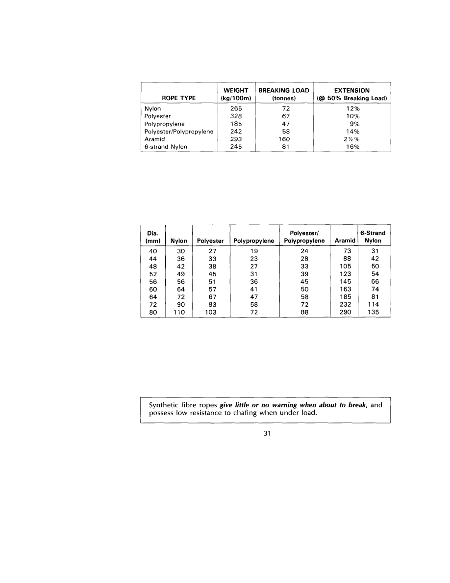
The table below gives the weight, breaking load and elasticity for a 64mm
diameter 8-strand plaited rope of different materials, and a 6-strand nylon rope.
The elasticity figures are those quoted by one manufacturer for used, worked ropes.
The extension is likely to be considerably greater for new ropes.
The following table gives comparative minimum breaking loads (in tonnes) for
a number of different 8-strand plaited ropes, and a six-strand nylon rope.
When delivered, all mooring ropes should be accompanied by a certificate
from the manufacturer which will indicate the minimum breaking load. These
certificates should always be consulted if it is necessary to ascertain the
specification of a particular rope.
NB: When wet, nylon has only 80% of its dry strength. It is the dry MBL which
is quoted and due allowance should be made when comparing with other
fibres, or when ordering nylon lines.
When making synthetic fibre ropes fast to bitts, do not use a "figure of 8" alone
to turn them up. Use two round turns (but not more) around the leading post
of the bitts before figure of eighting for large size bitts, or around both posts
before figure of eighting for bitts with smaller circumference posts. This
method allows better control of the rope, is easy to use and is safer.
Fig. 27
Rope Care
(a) Ropes must be kept clear of chemicals, chemical vapours or other harmful
substances. They should not be stored near paint or where they may be
exposed to paint or thinner vapours.
(b) Ropes should not be exposed to the sun longer than is necessary, as ultra-
violet light can cause fibres to deteriorate.
(c) Ropes must be visually inspected at regular intervals, and these inspec-
tions should include, so far as possible, inspection of the inner strands.
[Excessive wear in synthetic fibre ropes is indicated by powdering between
the strands and results in permanent elongation. This indicates a reduced
breaking load, and consideration must be given to replacing the rope. If
damage is localised, the worn or damaged part can be cut out and the
rope spliced.]
The inspection should include checking for the security of strands in
splices.
32

(d) Ropes must be stowed in a well ventilated compartment on wood gratings
to allow maximum air circulation and to encourage drainage.
(e) Do not store ropes in the vicinity of boilers or heaters; do not store them
against bulkheads or on decks which may reach high temperatures.
(f) Ensure that fairleads and warping drums are in good condition and free
from rust and paint. Roller heads should be lubricated and freely moving
to avoid friction damage to the rope.
(g) Do not surge ropes around drum end or bitts, as the friction temperature
generated may be high enough to melt the fibres.
(h) Do not drag ropes along the deck; if this is unavoidable, ensure that they
pass clear of sharp edges or rough surfaces.
(i) When using winch stored ropes, do not run them through leads which are
not on a direct line from the drum, as they are liable to chafe on the edge
of the spool.
Rope Stoppers
With the increased numbers and types of man-made fibre rope now available,
and the great strength of such ropes, it is essential that when "stopping off"
a mooring line the right rope stopper is used. Experience has shown that the
ideal rope for stoppers should satisfy the following requirements:
(a) The stopper should be of synthetic fibre rope.
(b) The stopper should be used "on the double".
(c) The stopper should be very flexible and the size should be as small as is
possible.
(d) The stopper rope should be of low stretch material.
(e) The man-made fibre ropes used for the stopper should be made from high
melting point material, ie. polyester or polyamide.
(f) The double rope used for the stopper should where possible have a
combined strength equal to 50% of the breaking load of the mooring rope
on which it is to be used.
33
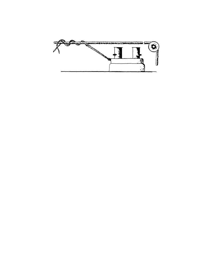
Fig. 28
Splicing
All splices must have a minimum of 5 tucks using ALL the rope strands and it
is important to whip all the strands before starting the splice. In the case of
plaited ropes, manufacturers normally issue detailed instructions as to how
they can be spliced.
When a rope is spliced, its breaking load is reduced by about 10%. However,
this figure does not increase if more than one splice is made in a rope.
Snapback
The most serious danger from synthetic ropes is "snapback" which is the
sudden release of the energy stored in the stretched synthetic line when it
breaks. The primary rule is to treat every synthetic line under load with extreme
caution; stand dear of the potential path of snapback whenever possible! Synthetic
lines normally break suddenly and without warning. Unlike wires, they do not
give audible signs of pending failure and they may not exhibit any broken
elements before completely parting.
When a line is loaded, it stretches. Energy is stored in the line in proportion
to the load and the stretch. When the line breaks, this energy is suddenly
released. The ends of the line snap back striking anything in their path with
tremendous force.
This snapback is common to all lines. Even long wire lines under tension can
stretch sufficiently to snap back with considerable energy. Synthetic lines are
much more elastic, and thus the danger of snapback is more severe.
Stand well clear of the potential path of snapback (see Fig. 29). The potential
path of snapback extends to the sides of and far beyond the ends of the
tensioned line.
34
Fig. 28 shows the correct method of stoppering off a synthetic mooring rope.
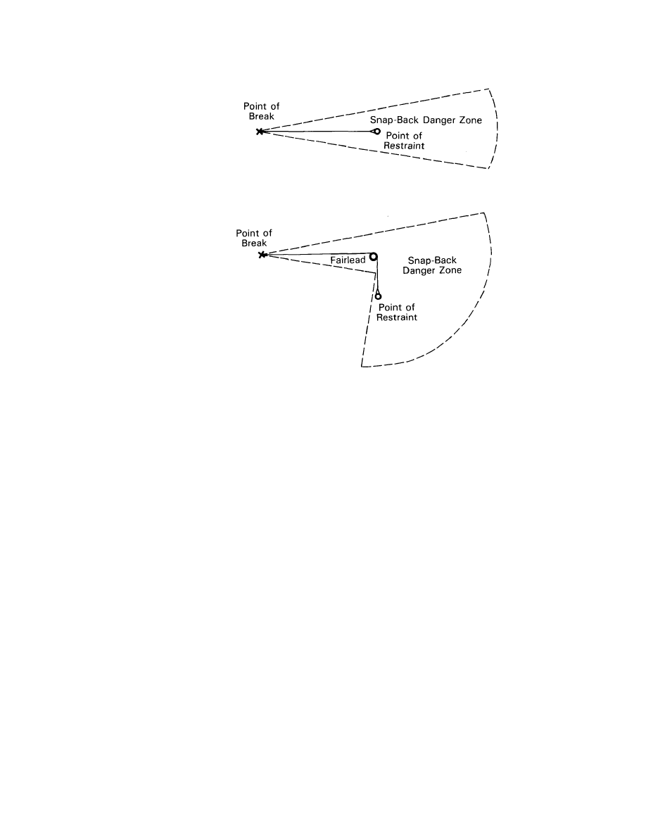
Fig. 29
A broken line will snap back beyond the point at which it is secured, possibly
to a distance almost as far as its own length. If the line passes around a fairlead,
then its snapback path may not follow the original path of the line. When it
breaks behind the fairlead, the end of the line will fly around and beyond the
fairlead.
It is not possible to predict all the potential danger zones from snapback. When
in doubt, stand aside and well away from any line under tension.
When it is necessary to pass near a line under tension, do so as quickly as
possible. If it is a mooring hawser and the ship is moving about, time your
passage for the period during which the line is under little or no tension. If
possible, do not stand or pass near the line while the line is being tensioned
or while the ship is being moved along the pier. If you must work near a line
under tension, do so quickly and get out of the danger zone as soon as possible
and plan your activity before you approach the line.
35
Chapter 5
MOORING AT BUOYS
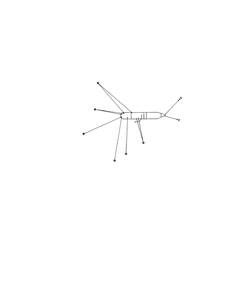
Conventional or Multibuoy Moorings (CBM or MBM)
Although there are many variations, the basic layout of such a berth is shown
in Fig. 30, with the ship moored in position using both anchors forward and
with the stern secured to buoys located around the stern.
Fig. 30
The mooring operation, which is often carried out without tugs, is difficult and
requires the full and efficient use of all the ship's mooring equipment.
The operation starts with the ship carrying out a "running moor" and, while it
is most common for the manoeuvre to be started with the stern buoys on the
port side of the ship to take advantage of the propeller thrust when the engine
is going astern, there are some berths where for a particular reason the
manoeuvre has to be started with the buoys to starboard. Fig. 31 shows the
different sfages of the operation.
37
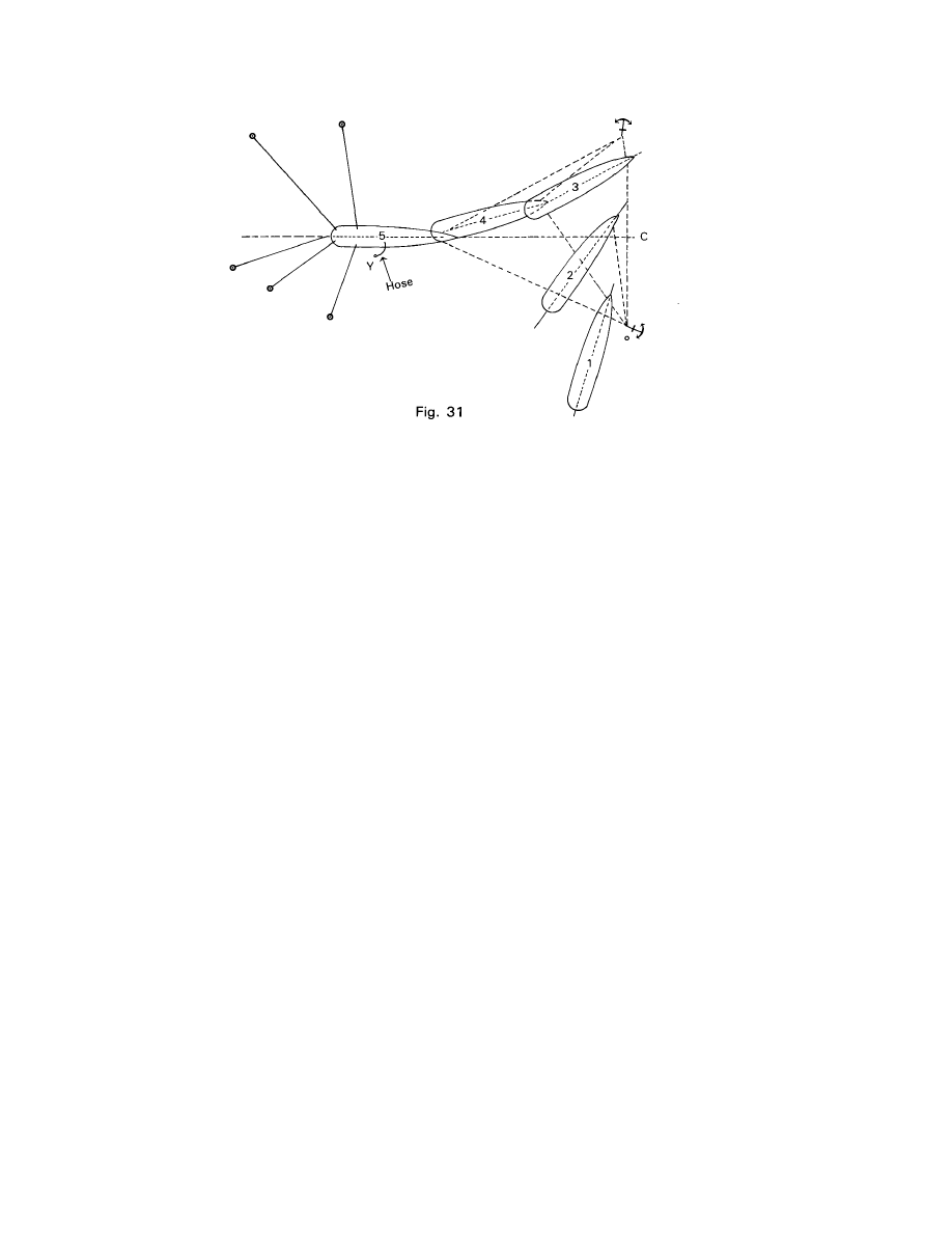
The tanker steams slowly towards the forward end of the berth in a line almost
perpendicular to her final position. At the correct moment, the starboard
anchor is let go and the cable is run out as the ship moves ahead, whilst the
engine is operated astern; when the ship is stopped in the water the port
anchor is let go. By careful manoeuvring of the engines and helm, and by
paying out on the port cable whilst heaving in on the starboard cable, the stern
of the ship is swing round so that it passes clear of the nearest buoy at the same
time as the ship is backing into the sector between the buoys. Mooring lines
have to be run to the buoys as quickly as possible in order to assist controlling
the swing and to assist in heaving the ship backwards into the berth.
Considerably higher loads than those experienced during a normal berthing
operation are imposed on the lines, and it is recommended that only lines on
drums be used during such an operation. Because of these higher than normal
loads, all the equipment should be thoroughly checked beforehand, and only
good quality lines should be used. The number of personnel required should
be kept to the essential minimum and should be restricted to experienced sea-
men. The mooring team should be briefed beforehand and should be under
the direct supervision of an experienced officer.
At many CBM's, the ships' moorings are often supplemented by shore wires
run from the buoys or from sub-sea platforms. The handling of these heavy
wires around the warping drum of a winch and thence to bitts, should be done
carefully by experienced seamen. When stopping off the wires prior to
securing to bitts, correctly sized carpenters stoppers should be used.
There are often lengthy periods when mooring boats are around the stern, or
mooring lines are in the water, and good comunications between poop and
bridge are essential to avoid boats or lines from being caught up in the
propeller.
38
Because the whole operation initially depends on dropping the first anchor in
the correct place, the approach line and dropping point are usually marked by
leading lines or ranges. If the anchor is let go too far away it is virtually
impossible to heave the ship into the berth using the lines alone; the best
option is to heave up and start again.
Because of the difficulties involved, some terminals provide their own
experienced mooring gangs for the berthing operation.
When unberthing, shore wires should be stoppered off with the carpenters
stopper, transferred to the winch drum and walked back, using slip wires as
necessary. Full length wires should never be let go "on the run", due to the
dangerous whipping action of the wire.
The ship's lines are then heaved in as the anchors are both weighed, and the
ship moves forward clear of the buoys. The windward mooring line is usually
the last one to be let go, in order to prevent the stern dropping on to the lee
buoys.
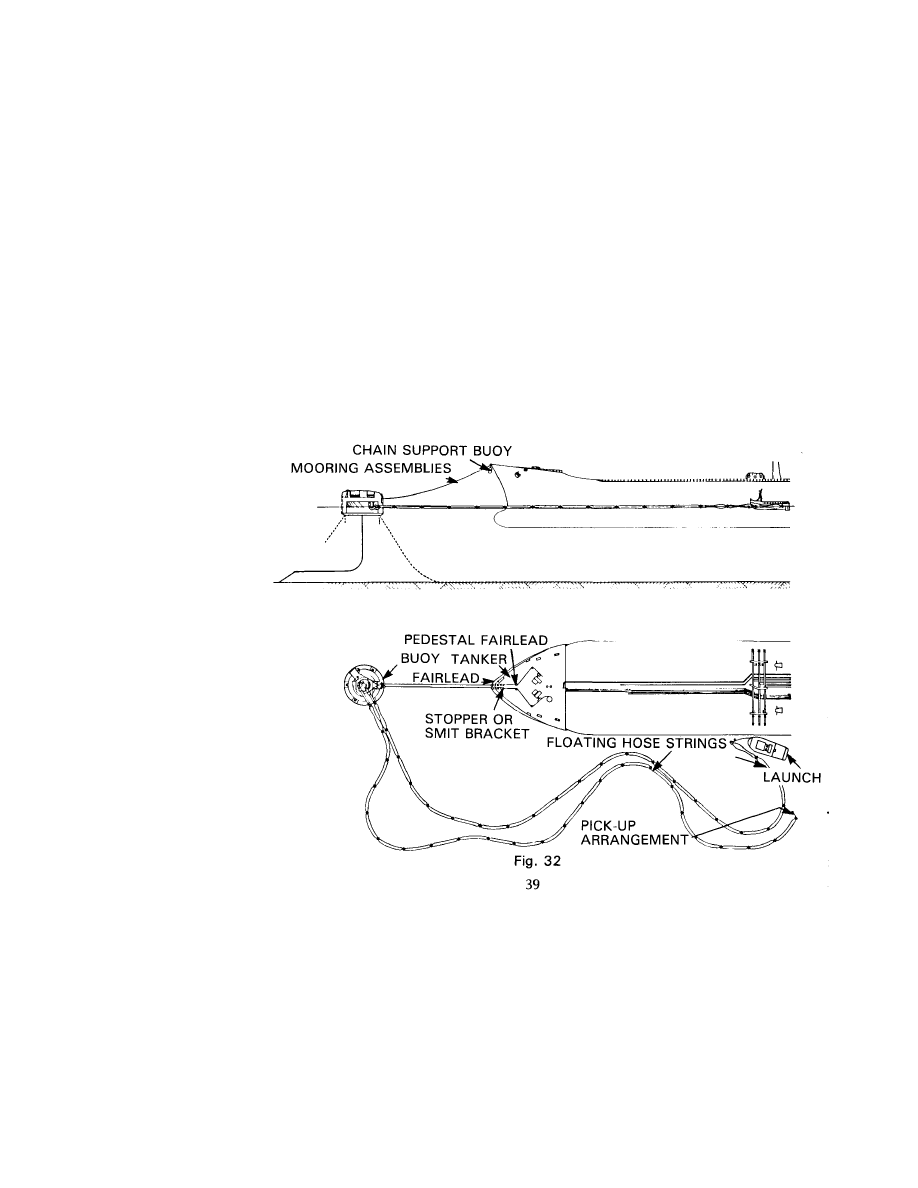
Single Buoy Mooring (SBM)
At an SBM the tanker bow is secured to the buoy using specially supplied
moorings which are attached to a swivel on the buoy, thus permitting the
tanker to swing around the buoy in response to wind and tides.
Because the ship is only moored at one point, all the load is borne by the one
or two mooring lines used. In addition to the normal static loads, considerable
dynamic (shock) loads are experienced as the ship moves to wind, tide and sea.
It is thus impracticable for the ship's normal mooring lines to be used, and the
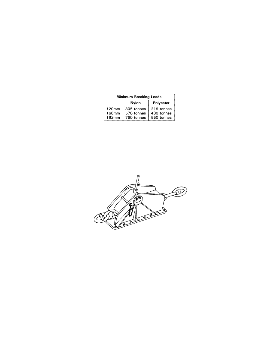
terminal always supplies special mooring lines. There are normally two lines
each of 120-190mm diameter made from nylon or polyester, giving very high
minimum breaking loads.
Obviously with the ship moving significantly, the hawsers would quickly chafe
on the fairlead. To overcome this, chafe chains are attached to the end of each
hawser and it is these chains which pass through the fairleads and are con-
nected on board to specially designed chain stoppers or brackets (see Fig. 33)
located on the focsle for this purpose. The chains are 76mm diameter links with
safe working loads of 250 tonnes (54mm SWL 100 tonnes for ships below
100,000 DWT).
Fig. 33 Tongue Type Chain Stopper
The chains and hawsers are supported by a buoy and attached to the end of
the chain is a floating polypropylene pick up rope 80mm diameter 150m long.
40

Before the ship commences her approach to the buoy, a messenger line should
be ready on the focsle running through one of the bow fairleads. This
messenger should be 75mm diameter and approximately 90 metres long and
should pass through the chain stopper before going to a winch. If possible, the
messenger should be secured around a winch drum so that the whole
operation can be carried out on a "hands off" basis.
The mooring operation is normally supervised by a pilot stationed on the bow.
He should be accompanied by a responsible officer who is in radio contact with
the bridge to pass on the pilot's instructions.
In order to avoid damage to submarine pipelines and SBM anchor chains, the
ship's anchor should not be dropped except in an extreme emergency.
When the ship is close to the SBM, the messenger is lowered to a mooring boat
where it will be connected to the pick up rope and when the boat is clear this
should be heaved on board. The pick up rope should be heaved in until the
chafe chain passes through the fairlead and reaches the required position. Care
should be taken when winching in the pick up rope and chain to ensure that
there is always some slack in the mooring assembly. It can be very dangerous
to the mooring crew if the assembly becomes tight before connection is
completed, and the ship should be carefully manoeuvred to ensure that this
does not occur. The pick up rope must never be used to heave the ship into
position or to maintain its position. Once the chafe chain is in position it should
be secured to the stopper as quickly as possible.
If the chain is to be attached to a special bracket (Smit bracket), the ship will
supply a mooring chain which should be connected to the bracket prior to
arrival. The chafe chain is heaved on board so that it passes close to the
mooring chain and is stoppered off using special chains and stoppers supplied
by the terminal. The chafe chain and mooring chain are then joined using a
specially designed shackle provided by the terminal.
Regardless of whether a stopper or bracket is used, once the chain is connected
the pick up rope should be walked back until the weight is transferred to
stopper or bracket.
Although tending of moorings is not required, an experienced crew member
should be posted forward at all times to observe the moorings and the SBM and
to advise if the tanker starts to ride up to the buoy or starts to yaw excessively.
When unmooring, the chains should be walked back into the water and the
pick up rope slowly paid out through the fairlead.
When mooring to either a CBM or an SBM, always have a few items of essential
equipment such as a large axe, sledgehammer, and crow bar readily available
to the crew.
41

Chapter 6
WINDLASSES AND ANCHORING
It is essential that you read your company's rules and regulations concerning
anchoring. They will give clear directions for anchoring procedures. Never-
theless, anchor losses sometimes occur on all classes of vessel and have mainly
been attributed to:
(a) Too great a speed over the ground.
(b) Too little cable being paid out during the initial lowering of the anchor
prior to letting go.
The risk of anchor and cable losses, particularly on large ships such as VLCCs,
can be minimised by:
(a) Ensuring minimum or nil speed over the ground by using doppler log
(where fitted) or other navigational aids. As a final check, the anchor can
be lowered to just touch the bottom to confirm the Master's judgement
that the ship has ceased to make way over the ground.
(b) The fitting of a speed limiter to the windlass.
(c) In all cases, the anchor should be "walked" (ie. lowered with the windlass
in gear) out of the hawse pipe until just clear of the seabed, thus reducing
the amount of "freefall" of the anchor and cable.
(d) Anchoring with the windlass in gear. This gives good control over the
anchor and cable throughout the operation. It also helps to maintain
brake efficiency by reducing wear of the brake lining.
In all cases, care must be taken to avoid over speeding of the windlass engines
to avoid damage.
Brakes
These will be most effective if tightened up at the moment that the maximum
weight comes on to the anchor cable. Further adjustment should then be
unnecessary, as the changes in load due to changing tides and wind will be
borne by the cable stopper.
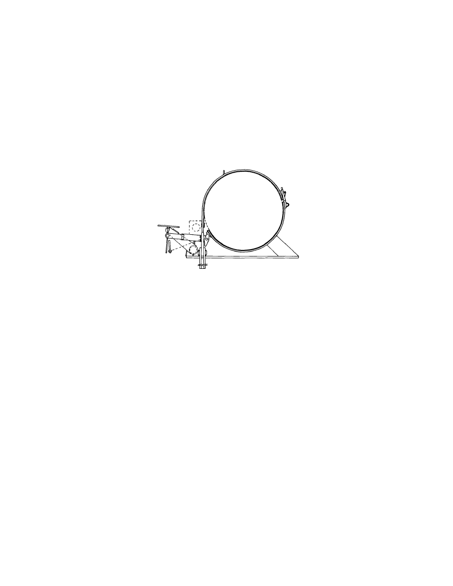
Cable Stoppers
Cable stoppers form an integral part of the anchor cable restraining equipment
and are designed to take the anchoring loads. Cable stoppers must be used
when the vessel is anchored, and must be applied only after the brake has been
set to ensure that the brake augments the action of the stopper for additional
security. Fig. 34 shows the correct way to fit a stopper.
43
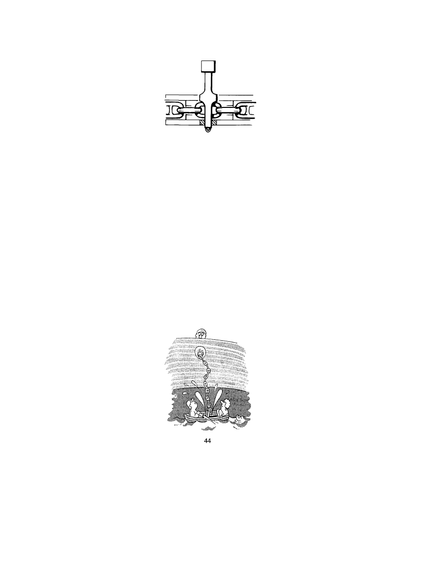
Fig. 34
Consideration may also be given to tying down the cable stopper whenever it
is in use, in order to prevent it jumping when under a heavy load.
Cable stoppers must also be in position, together with the securing chains,
when the anchor is "home" in the pipe.
Anchor Cables
It is very important that anchor cable lengths are clearly marked with white
paint and if possible, stainless steel bands, even when cable counters are fitted.
It is also advisable to paint the second shackle from the bitter end red. This will
serve as a visual warning of the approach of the end of the anchor cable.
Communication
If you are charged with the duty of controlling the anchor during an anchoring
operation, be sure that the bridge is aware of precisely what is happening or could
happen, as the Master is, to a large degree, dependent upon your information.
Before lowering the anchor, or indeed, heaving in, check over side for small
boats, tugs, etc.
Maintenance of Windlass Brakes
Windlass brakes require careful attention with regard to greasing and
adjustment.
Where linkages form part of the braking mechanism, it is important that the
linkages are free.
Malfunction can cause the operator to believe that the brake is fully applied
when, in fact, it is not.
It is also most important to inspect the tightness of bearing keep nuts and
cotter pins, especially after a refit, where it is known that work has been carried
out on the assembly.
Fig. 35 Typical brake arrangement
Adjustments
Provision is sometimes made to compensate for brake lining wear. Consult the
Maker's instructions and make sure you are familiar with this facility.
If in doubt about the brake holding efficiency — REPORT IT!
Prolonged Periods of Non-Use
After a long sea passage and a port call not requiring the use of either anchor,
consideration should be given to a controlled walking out (ie. windlass in gear)
of the anchors and cable to ensure that the system is still fully operational.
Greasing of bearings, brake linkages, etc, should be carried out during this
operation.
45
46
Chapter 7
PERSONAL SAFETY
Handling of Moorings
REMEMBER, you stand a greater risk of injuring yourself or your shipmate, during
mooring and unmooring operations than at any other time.
STAND CLEAR of all wires and ropes under heavy loads even when not directly
involved in their handling.
When paying out wires or ropes, watch that both your own and shipmate's feet are
not in the coil or loop. BEWARE THE BIGHT!
Beware the Bight!!
Always endeavour to remain in control of the line.
Anticipate and prevent situations arising that may cause a line to run
unchecked. If the line does take charge, DO NOT attempt to stop it with your feet
or hands as this can result in serious injury.
Ensure that the "tail end" of the line is secured on board to prevent complete
loss.
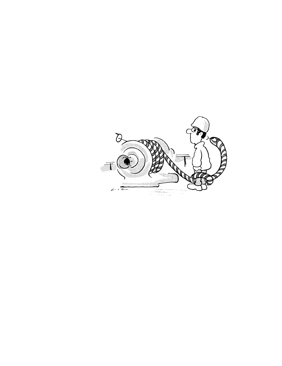
WHEN OPERATING A WINCH OR WINDLASS, ensure that the man (or yourself)
understands the controls and CAN SEE the officer or person in charge for
instructions.
47
DO NOT leave winches and windlasses running unattended.
DO NOT stand on the machinery itself to get a better view.
DO NOT use a wire direct from a stowage reel that has been designed only for
stowing, but do make sure you have enough wire off the reel before you put it
into use.
When using a Double Barrel Winch, ensure that the drum not in use is clear.
Safe Handling of Tug Lines
When tugs are used to assist manoeuvring the ship, additional care is required
by the ship's crew.
The condition of the tug's lines is unknown, and the crew on mooring stations
will not normally be aware of when the tug is actually heaving or what load is
being applied to the line. It is therefore important to stay well dear of the tow
line at all times.
When the tug is being secured or let go, the person in charge of the mooring
should monitor the operation closely to ensure that no load comes on to the
line before it is properly secured, or whilst it is being let go.
Never let a tug go until instructed to do so from the bridge; do not respond
to directions from the tug's crew.
If the tow line has an eye on it, heave this past the bitts so that there is sufficient
slack line to work with, stopper off the line, then put the eye on the bitts. Do
not try to manhandle a line on to the bitt if there is insufficient slack line. If the
line has no eye and is to be turned up on the bitts then it should always be
stoppered off before handling it.
48
Do not try to hold a line in position by standing on it just because it is slack
— if the tug moves away so will you!
When letting go do not simply throw the line off the bitts and let it run out;
always slack it back to the fairlead in a controlled manner, using a messenger
line if necessary to avoid whiplash.
Gloves
Gloves protect the hands against abrasion and also give insulation against very
hot or cold conditions, both of which could affect a person's handling of
equipment.
Wire should not be handled without leather or similar heavy protective gloves.
These can prevent wounds caused by "snags" (broken wire strands). Such
wounds may become infected and may bring about medical complications.
Loose fitting gloves are more liable to become trapped between wires and
other equipment such as drum ends or bollards and do not give the necessary
degree of protection.
In any event, it must always be remembered that gloves cannot be relied upon
to give complete protection against snags in the wire. Also, that such snags may
catch in the material and endanger life and limb through trapping.
Such an event can be prevented by attention to the good practices described
in this book.
49
50
Document Outline
- Cover page
- Foreword
- Equivalents
- Contents
- Chapter 1 Effective mooring
- Chapter 2 Mooring winches
- Chapter 3 Steel wire ropes
- Chapter 4 Synthetic fibre ropes
- Chapter 5 Mooring at buoys
- Chapter 6 Windlasses and Anchoring
- Chapter 7 Personal Safety
- Handling of moorings
- Safe handling of tug lines
- Gloves
- Safety remainders
Wyszukiwarka
Podobne podstrony:
EXPORTS OF ICT EQUIPMENT
Improvised Explosive Devices Booklet of Related Readings
Paranoia Equipment Weapon Vehicle Request Form
DSP Facts and Equipment
Pierscien booklet
I AD06 F02 Fire fighting equipment
I AD06 F01 Rescue equipment
Booklet Portuguese
OCIMF MEG part2
FRC BASIC EQUIPMENT
OCIMF HVPQ 2009 (newest) Rev1 02Jun09
Notes on the 3 inch gun materiel and field artillery equipment 1917
Cthulhu Rising ICM Equipment
History HL+SL paper 1 resources booklet
I-AD14-F03 Equipment for enclosed lifeboat, Akademia Morska, Chipolbrok
Damage Control Booklet CV for S Nieznany
Japanese II Reading Booklet
Polish Sports Equipment Sprzręt Sportowy 4
więcej podobnych podstron