BRAKE SYSTEM
S3.50-5.50XM (S70-120XM) [E004, F004]
PART NO. 1510466
1800 SRM 985

SAFETY PRECAUTIONS
MAINTENANCE AND REPAIR
• When lifting parts or assemblies, make sure all slings, chains, or cables are correctly
fastened, and that the load being lifted is balanced. Make sure the crane, cables, and
chains have the capacity to support the weight of the load.
• Do not lift heavy parts by hand, use a lifting mechanism.
• Wear safety glasses.
• DISCONNECT THE BATTERY CONNECTOR before doing any maintenance or repair
on electric lift trucks. Disconnect the battery ground cable on internal combustion lift
trucks.
• Always use correct blocks to prevent the unit from rolling or falling. See HOW TO PUT
THE LIFT TRUCK ON BLOCKS in the Operating Manual or the Periodic Mainte-
nance section.
• Keep the unit clean and the working area clean and orderly.
• Use the correct tools for the job.
• Keep the tools clean and in good condition.
• Always use HYSTER APPROVED parts when making repairs. Replacement parts
must meet or exceed the specifications of the original equipment manufacturer.
• Make sure all nuts, bolts, snap rings, and other fastening devices are removed before
using force to remove parts.
• Always fasten a DO NOT OPERATE tag to the controls of the unit when making repairs,
or if the unit needs repairs.
• Be sure to follow the WARNING and CAUTION notes in the instructions.
• Gasoline, Liquid Petroleum Gas (LPG), Compressed Natural Gas (CNG), and Diesel fuel
are flammable. Be sure to follow the necessary safety precautions when handling these
fuels and when working on these fuel systems.
• Batteries generate flammable gas when they are being charged. Keep fire and sparks
away from the area. Make sure the area is well ventilated.
NOTE: The following symbols and words indicate safety information in this
manual:
WARNING
Indicates a condition that can cause immediate death or injury!
CAUTION
Indicates a condition that can cause property damage!

Brake System
Table of Contents
TABLE OF CONTENTS
General ...............................................................................................................................................................
Description and Operation ................................................................................................................................
Brake Booster and Master Cylinder .............................................................................................................
Service Brake Assembly ................................................................................................................................
Parking Brake................................................................................................................................................
Brake Shoe Assemblies Repair .........................................................................................................................
Remove and Disassemble ..............................................................................................................................
Clean ..............................................................................................................................................................
Inspect ............................................................................................................................................................
Assemble and Install .....................................................................................................................................
Brake Booster and Master Cylinder .................................................................................................................
Remove ...........................................................................................................................................................
Disassemble ...................................................................................................................................................
Clean and Inspect ..........................................................................................................................................
Assemble ........................................................................................................................................................
Install .............................................................................................................................................................
Brake Booster Filter, Replace .......................................................................................................................
Parking Brake Repair........................................................................................................................................
Remove and Disassemble ..............................................................................................................................
Assemble and Install .....................................................................................................................................
Brake System Air Removal ...............................................................................................................................
Brake Pedal Adjustment ...................................................................................................................................
Parking Brake Adjustment ...............................................................................................................................
Parking Brake Not Applied Switch Test...........................................................................................................
Parking Brake Switch Test (MONOTROL
®
Pedal Only).................................................................................
Brake Shoes Adjustment ...................................................................................................................................
Troubleshooting..................................................................................................................................................
This section is for the following models:
S3.50-5.50XM (S70-120XM) [E004, F004]
©2005 HYSTER COMPANY
i

"THE
QUALITY
KEEPERS"
HYSTER
APPROVED
PARTS
1800 SRM 985
Description and Operation
General
This section contains a description and repair procedures for parts of the hydraulic brake system. These parts
include the brake booster, master cylinder, and brake shoe assemblies.
Description and Operation
The brake pedal is connected to the push rod for the
brake booster. The brake booster helps increase the
force on the master cylinder by using vacuum from
the engine. The piston in the master cylinder forces
oil to the wheel cylinders to apply the brakes. The
system allows braking without vacuum from the en-
gine.
BRAKE BOOSTER AND MASTER
CYLINDER
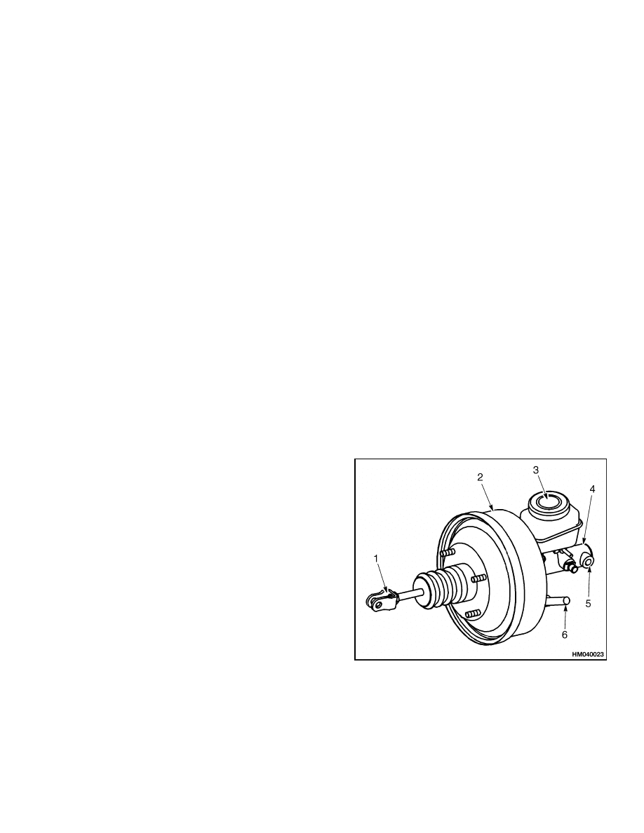
The brake booster and master cylinder are assembled
as a unit. The brake booster has a diaphragm that is
actuated by engine vacuum. See Figure 1. The di-
aphragm along with the operator’s effort pushes on
the piston in the master cylinder. Hydraulic pres-
sure actuates wheel cylinders as the piston pushes
fluid through check valve. A return spring pushes
piston back to the stop plate when pedal is released.
Fluid can flow through passages in piston and past
the primary cup as piston returns. Fluid flows across
the piston to prevent a vacuum while fluid returns
through the check valve. When piston passes the
compensator port, excess fluid from brake system re-
turns to the reservoir. The check valve keeps a very
small amount of pressure in brake system. The reser-
voir for brake fluid has a sending unit for a low fluid
level warning light.
SERVICE BRAKE ASSEMBLY
Service brake assemblies are installed at each end of
the housing for the drive axle. Each service brake
assembly has a single wheel cylinder at the top of
each back plate. The support plate has an anchor
for each shoe. When wheel cylinder is actuated by
fluid pressure from the master cylinder, the shoes
expand against the drum. The primary shoe starts
to turn with the drum. This action pushes secondary
shoe tight against drum and anchor. When lift truck
is traveling in reverse, the primary shoe is pushed
against anchor and drum by the secondary shoe.
The automatic adjusting linkage turns adjuster
screw wheel to adjust clearance between brake
shoes and brake drum.
The secondary shoe and
links move with the drum during a stop when the
truck is traveling in reverse.
The links permit
the adjuster spring lever to rotate the adjuster
screw wheel.
The adjuster screw wheel will only
turn when there is clearance between the lining and
brake drum. The adjuster screw wheel can be turned
manually through a slot in the back plate.
PARKING BRAKE
The parking brake uses the service brake shoes.
Additional linkage pushes brake shoes apart when
the hand lever pulls the cables.
A switch on the
right-hand side of mounting bracket is actuated by
the hand lever. On all units, the switch energizes the
seat warning circuit when hand lever is released. On
units with a MONOTROL
®
pedal, this switch puts
the transmission in NEUTRAL by de-energizing the
direction solenoids. On units with a MONOTROL
pedal, there is also a switch on left-hand side of
bracket. This switch prevents engine from starting
unless parking brake is applied.
1.
PUSH ROD
2.
BRAKE BOOSTER
3.
RESERVOIR
4.
MASTER
CYLINDER
5.
OUTLET
TO WHEEL
CYLINDERS
6.
ENGINE VACUUM
CONNECTION
Figure 1. Brake Booster and Master Cylinder
1

Brake Shoe Assemblies Repair
1800 SRM 985
Brake Shoe Assemblies Repair
REMOVE AND DISASSEMBLE
WARNING
Brake linings can contain dangerous fibers.
Breathing dust from these brake linings is
a cancer or lung disease hazard.
Do not
create dust!
Do not clean brake parts with
compressed air or by brushing. Use vacuum
equipment approved for brake dust or fol-
low cleaning procedure in this section. When
brake drums are removed, do not create dust.
Do not sand, grind, chisel, hammer, or change
linings in any way that will create dust. Any
changes to linings must be done in a restricted
area with special ventilation. Protective cloth-
ing and a respirator must be used.
1.
Tilt mast back and put blocks under outer mast
weldment. Tilt mast forward to raise tires from
floor.
2.
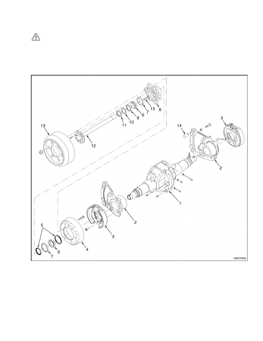
Remove wheel nuts, then remove wheels. Put
capscrews (16 mm) in threaded holes to push
brake drums from hubs. See Figure 2.
3.
Remove capscrews holding axle shaft to wheel
hub. Remove axle shaft.
4.
Remove lock nut, lockplate, and bearing adjust-
ment nut from axle housing. Remove outer bear-
ing cone. See Figure 2.
5.
Remove hub from axle housing. Remove inner
seals and bearing cone from hub.
WARNING
When the brake shoes are removed, do not cre-
ate dust in the air. See the cleaning procedures
in this section.
6.
Turn adjuster screw to loosen brake shoes. Dis-
connect linkage for automatic adjuster. See Fig-
ure 3.
7.
Use spring pliers to remove shoe return springs.
8.
Remove hold down springs.
CAUTION
The adjuster screw assemblies are not the
same. Make sure each assembly has identifica-
tion for installation on the correct side of the
axle.
9.
Remove brake shoes from wheel cylinder rods.
Remove adjuster screw spring. Remove adjuster
screw assembly. See Figure 3.
10. Remove parking brake cable from parking brake
lever. Remove lever from rear brake shoe.
11. Disconnect and put a cap on the line to the wheel
cylinder. Remove backplate. Remove capscrews
holding wheel cylinder to backplate. Remove ca-
ble clamp and pull cable through backplate.
CLEAN
WARNING
Brake linings can contain dangerous fibers.
Breathing dust from these brake linings is
a cancer or lung disease hazard.
Do not
create dust!
Do not clean brake parts with
compressed air or by brushing. Use vacuum
equipment approved for brake dust or fol-
low cleaning procedure in this section. When
brake drums are removed, do not create dust.
Do not sand, grind, chisel, hammer, or change
linings in any way that will create dust. Any
changes to linings must be done in a restricted
area with special ventilation. Protective cloth-
ing and a respirator must be used.
1.
Do not release brake lining dust from brake lin-
ings into air when brake drums are removed.
2.
Use a solvent approved for cleaning of brake
parts to wet brake lining dust. Follow instruc-
tions and cautions of manufacturer for use of
solvent. If a solvent spray is used, do not create
dust with spray.
2
1800 SRM 985
Brake Shoe Assemblies Repair
CAUTION
Do not use an oil solvent to clean wheel cylin-
der.
Use a solvent approved for cleaning of
brake parts.
Do not permit oil or grease in
brake fluid or on brake linings.
3.
When dust is wet, clean brake parts. Put any
cloth or towels in a plastic bag or airtight con-
tainer while they are still wet. Put a DANGER-
OUS FIBERS warning label on plastic bag or air-
tight container.
4.
Any cleaning cloths that will be washed must be
cleaned so fibers are not released into the air.
1.
AXLE HOUSING
2.
AXLE MOUNT
3.
BRAKE ASSEMBLY (SHOES AND BACKPLATES)
4.
BRAKE DRUM
5.
SEAL
6.
BEARING CONE
7.
BEARING CUP
8.
WHEEL HUB
9.
ADJUSTMENT NUT
10. LOCKWASHER
11. LOCK NUT
12. AXLE SHAFT
13. TIRE AND WHEEL
14. MOUNTING PIN
15. DOWEL PIN
Figure 2. Brakes and Drive Axle Assembly
3
Brake Shoe Assemblies Repair
1800 SRM 985
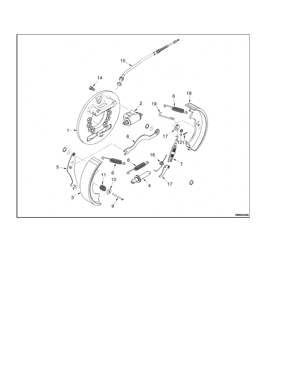
NOTE: LEFT-HAND SIDE SHOWN.
1.
BACKING PLATE
2.
WHEEL CYLINDER ASSEMBLY
3.
REAR BRAKE SHOE
4.
ADJUSTER SCREW
5.
PARKING BRAKE LEVER
6.
SHOE RETURN SPRING
7.
SPRING AND LINK ASSEMBLY
8.
STRUT
9.
SHOE HOLDDOWN PIN
10. SHOE HOLDDOWN CUP
11. SHOE HOLDDOWN SPRING
12. WASHER
13. COTTER PIN
14. BOLT
15. BRAKE LINE
16. SPRING
17. LEVER
18. FRONT BRAKE SHOE
19. LINK
Figure 3. Service Brakes
4
1800 SRM 985
Brake Shoe Assemblies Repair
INSPECT
WARNING
Cleaning solvents can be flammable and toxic
and can cause skin irritation.
When using
cleaning solvents, always follow the recom-
mendations of the manufacturer.
1.
Clean all metal parts except brake linings and
wheel cylinder with solvent.
2.
Check bore of wheel cylinder for holes or
scratches.
Replace wheel cylinder if there is
any damage.
3.
Check return springs for damage. Inspect back-
plate for wear where brake shoes touch back-
plate.
WARNING
The brake shoes on both wheels must be re-
placed if any shoe is damaged.
The brake
performance on both ends of an axle must be
equal, or lift truck can be difficult to steer
when brakes are applied.
4.
Inspect brake shoes for cracks or damage. If lin-
ings or shoes are worn or damaged, replace brake
shoes. It is recommended that brake shoes be re-
placed in complete sets.
5.
Check adjuster screw wheel for wear. Make sure
adjuster screw turns. Check for bent or broken
adjuster links.
NOTE: If the brake drums require grinding, do not
grind more than 1.5 mm (0.060 in.) from the diam-
eter. The maximum inside diameter of the brake
drum, including wear, is 319.5 mm (12.58 in.). If
brake drum is larger than this, replace brake drum.
6.
Inspect brake drums for cracks or damage. Use
sandpaper to clean surface for brake shoes.
ASSEMBLE AND INSTALL
1.
Install wheel cylinder on backplate. Push park-
ing brake cable through backplate and fasten
clamp. See Figure 3.
2.
Use a sealant (Hyster Part No. 264159) between
backplate and axle hanger.
Install backplate
to axle mounts.
See Figure 2.
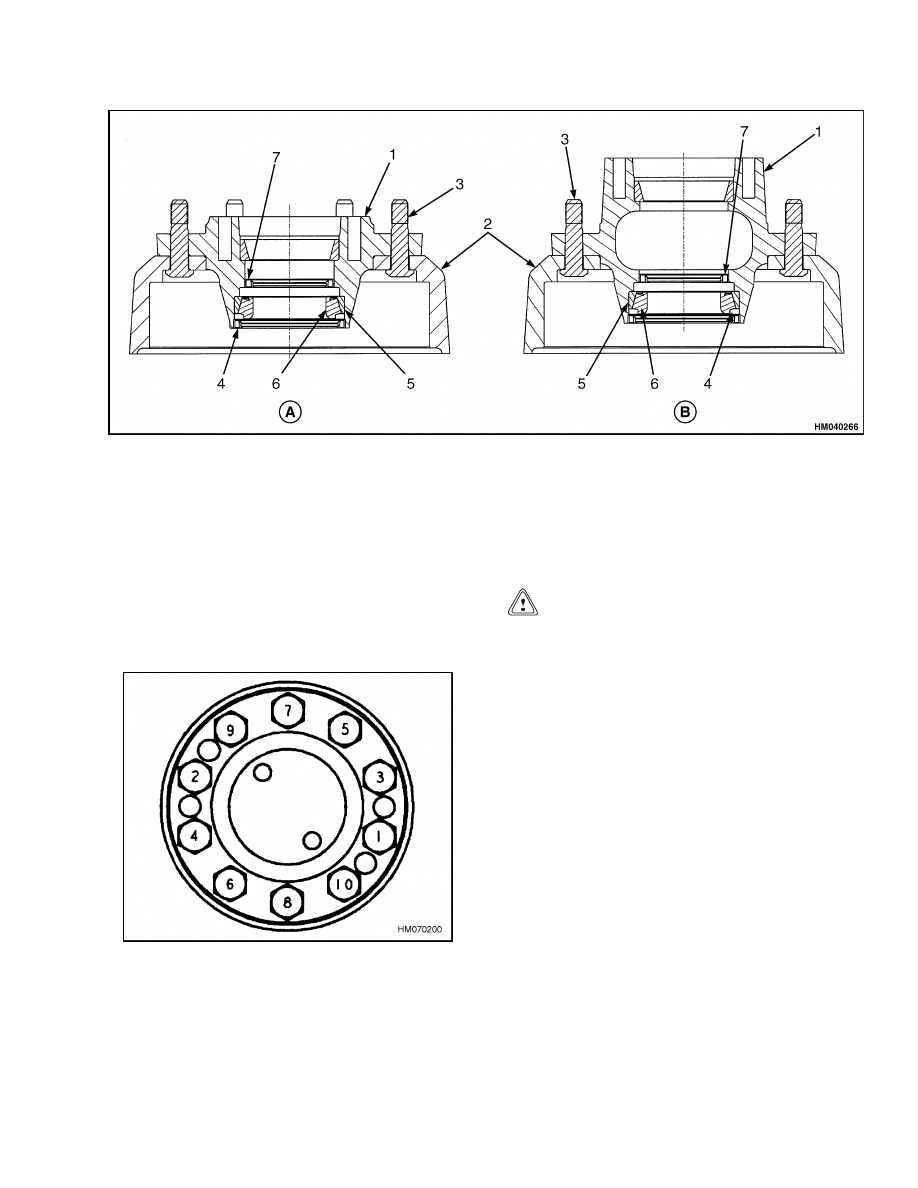
Use sequence
shown in Figure 4 and tighten capscrews to 340
to 375 N•m (250 to 275 lbf ft).
Figure 4. Backplate Installation
3.
Connect brake line to fitting on wheel cylinder.
4.
Install link pivot on front brake shoe. Install
parking brake lever on rear brake shoe. Install
anchor pins in the support flange so they engage
brake shoes.
5.
Lubricate the back plate with a small amount of
grease where the brake shoes touch. Install the
brake shoes on the anchor and engage the push
rods of the wheel cylinder. Engage the parking
brake lever in the slot in the parking brake cable
as the brake shoes are installed on the back plate.
6.
Put an anchor pin that holds the brake shoes
through the back plate. Put a spring seat, spring,
and retainer on the anchor pin. Push the retainer
onto the anchor pin and rotate the retainer 90
degrees. Make sure the retainer is in the correct
position. Install another retainer spring assem-
bly.
7.
Install the link, parking brake, and spring be-
tween the parking brake lever and the brake
shoe.
NOTE: The forward shoe return spring is marked
with white paint.
8.
Using the correct tools, install the return springs.
9.
Verify that the return springs are properly in-
stalled.
10. Connect cable for parking brake to lever.
5
Brake Shoe Assemblies Repair
1800 SRM 985
WARNING
The threads of the adjuster wheel are not the
same for each side. If the adjuster assemblies
are installed on the wrong side, the brake
shoe clearance will increase each time the
brakes are applied.
The adjuster wheel for
the right brake has left-hand threads. The ad-
juster wheel for the left brake has right-hand
threads.
11. Lubricate adjuster screw with antiseize com-
pound.
Turn adjuster screw to retract brake
shoes. Install adjuster between shoes.
12. Align adjuster screw wheel with slot in back-
plate.
13. Install adjuster spring with long hook toward ad-
juster screw wheel.
14. Install adjuster spring lever and two links.
CAUTION
Do not damage the seals when you install the
hub assembly.
15. Use new oil seals. Install inner seal, bearing
cups, and outer seal in hub. Install inner bear-
ing cone on spindle. Lubricate inner bearing with
grease. See Figure 5 and Figure 6.
16. Install hub on spindle. See Figure 5 and Figure 6.
Lubricate outer bearing cone with 80W-90 oil for
gears. Install outer bearing cone and adjustment
nut.
17. Tighten adjustment nut to 203 N•m (150 lbf ft)
while rotating hub until hub does not turn.
Loosen nut until hub rotates freely with NO
end play. The torque must be less than 27 N•m
(20 lbf ft). Tighten nut to 34 N•m (25 lbf ft)
or to the first alignment position after 34 N•m
(25 lbf ft). Install lockwasher to hold the nut.
Install lock nut and tighten it to 135 N•m
(100 lbf ft).
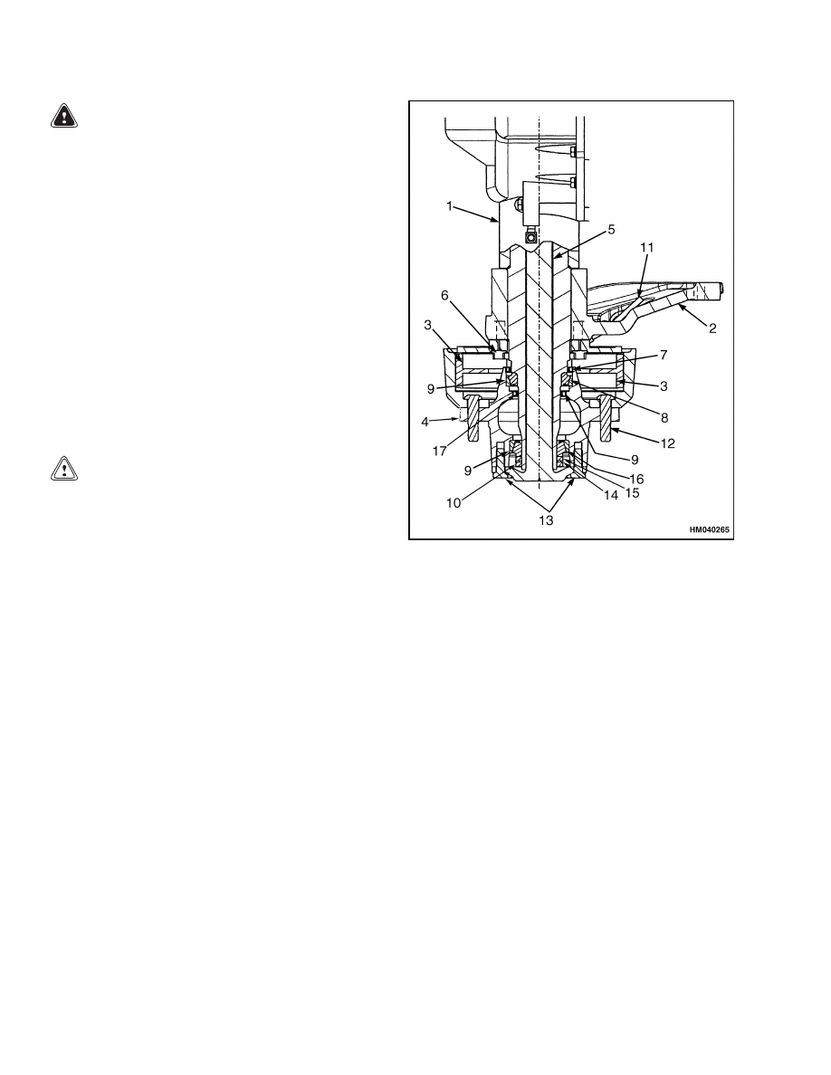
NOTE: LONG-WHEEL BASE HUB SHOWN
1.
AXLE HOUSING
2.
AXLE MOUNT
3.
BRAKE SYSTEM
4.
HUB ASSEMBLY
5.
AXLE SHAFT
6.
DURALOCK BOLTS
7.
OUTER SEAL
8.
OUTER BEARING
9.
BEARING CUP
10. LOCK NUT -
WHEEL NUT
11. BRAKE HOSE
12. SERRATED BOLTS
13. AXLE SHAFT
BOLTS
14. LOCKWASHER
15. LOCK NUT -
WHEEL BEARINGS
16. INNER BEARING
17. INNER SEAL
Figure 5. Brake Assembly
18. Install brake drum and adjust brake shoes as de-
scribed in Brake Shoes Adjustment.
6
1800 SRM 985
Brake Shoe Assemblies Repair
A. SHORT WHEEL BASE HUB ASSEMBLY
B. LONG WHEEL BASE HUB ASSEMBLY
1.
HUB
2.
BRAKE DRUM
3.
SERRATED HUB BOLT
4.
OUTER SEAL
5.
ROLLER BEARING CUP
6.
BEARING CONE
7.
INNER SEAL
Figure 6. Hub Assembly
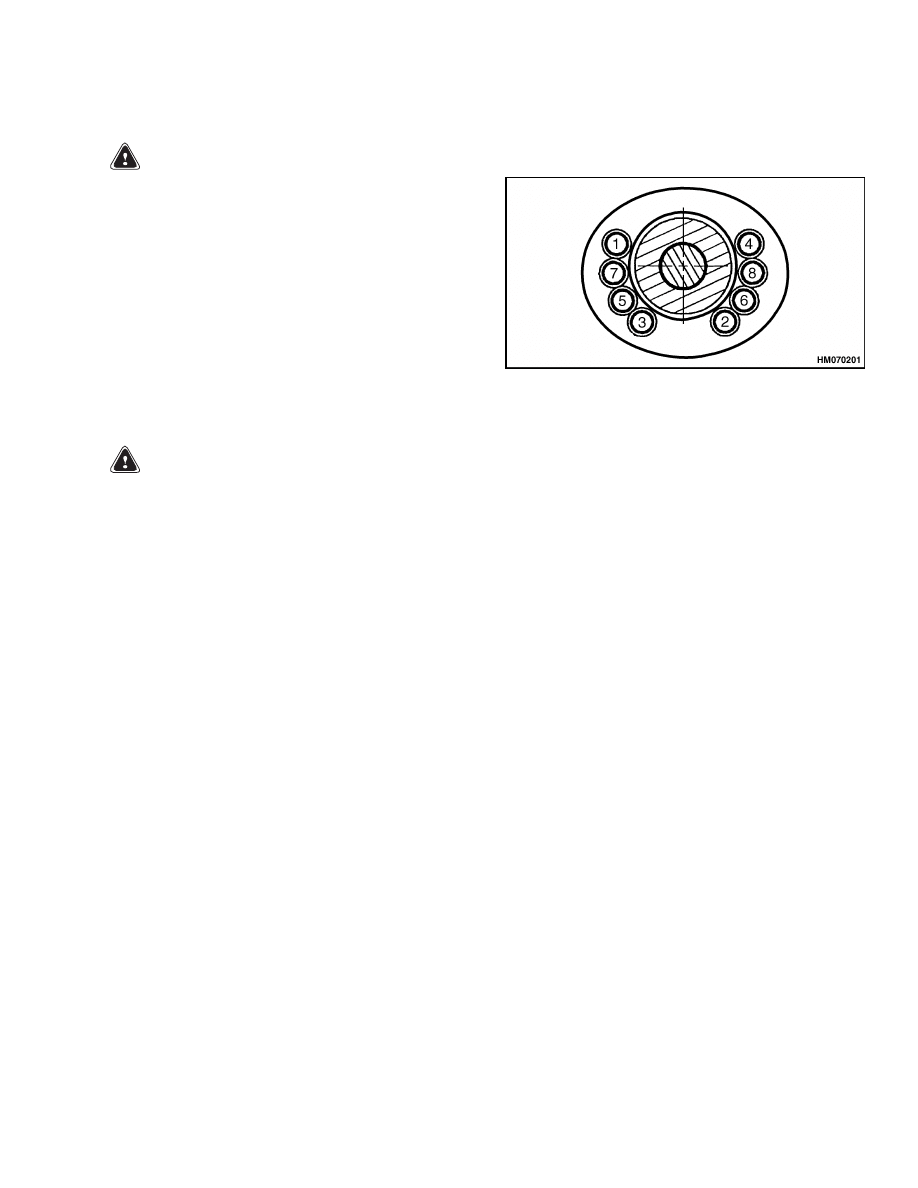
19. Apply sealant (Hyster Part No. 264159) to flange
of axle shaft. Install axle shaft. See Figure 2.
Tighten capscrews to 225 N•m (166 lbf ft). See
Figure 7.
Figure 7. Axle Shaft Tightening Sequence
CAUTION
When the wheels have been installed, check
all wheel nuts after 2 to 5 hours of operation.
Tighten the nuts to the correct torque. When
the nuts stay tight after an 8-hour check, the
interval for checking can be extended to 500
hours.
20. Install wheel.
Tighten wheel nuts to 610 to
680 N•m (450 to 500 lbf ft).
21. Remove air from brake system and adjust
brakes.
See Brake Shoes Adjustment in this
section.
7

Brake Booster and Master Cylinder
1800 SRM 985
Brake Booster and Master Cylinder
REMOVE
1.
Disconnect push rod from inching crank.
See
Figure 8. Disconnect brake line at master cylin-
der. Cover end of brake line. Disconnect wires at
reservoir.
2.
Remove nuts that hold brake booster to mount.
3.
Remove brake booster and master cylinder.
DISASSEMBLE
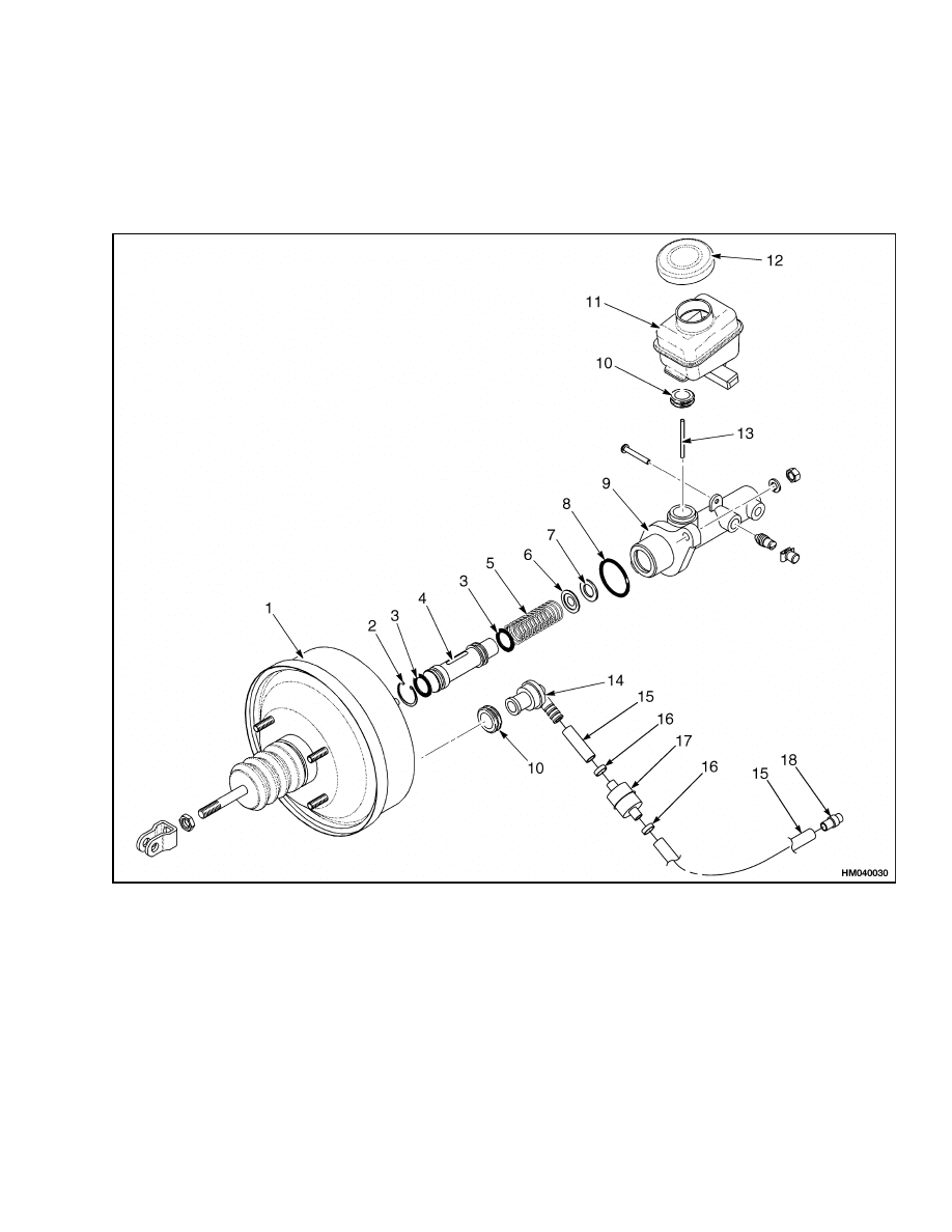
NOTE: Do not disassemble the brake booster. Repair
parts are not available.
1.
Remove nuts that hold master cylinder to brake
booster. See Figure 9.
WARNING
There is a compressed spring behind the pis-
ton. To prevent possible injury, use care when
removing the snap ring and piston.
2.
Remove snap ring from end of master cylinder.
Carefully remove piston and spring from bore.
3.
Remove seals from piston.
CLEAN AND INSPECT
CAUTION
DO NOT use an oil solvent to clean the master
cylinder. Use a solvent approved for cleaning
of brake parts.
Inspect bore of master cylinder for holes or scratches.
Replace master cylinder assembly if there is damage.
ASSEMBLE
NOTE: Lubricate parts of master cylinder with clean
brake fluid.
1.
Install seals on piston. Install seat, check valve,
and spring in bore. Install spring and piston.
Install snap ring in bore. See Figure 9.
2.
Install O-ring and master cylinder on brake
booster.
INSTALL
1.
Put master cylinder in position on brake booster
and install nuts for master cylinder.
Install
brake booster on mount.
2.
Install nuts for brake booster. Connect push rod
to inching crank. See Figure 8.
3.
Connect brake line at master cylinder. Connect
wires at reservoir.
4.
Fill reservoir and remove air from brake system
as described in Brake System Air Removal in this
section.
5.
Adjust brake linkage as described in Brake Pedal
Adjustment.
BRAKE BOOSTER FILTER, REPLACE
1.
Remove the two clamps holding the old filter
to the brake vacuum lines. Remove the brake
booster filter. See Figure 9.
2.
Install new filter onto brake vacuum lines. In-
stall the two clamps to hold brake booster filter
onto brake vacuum lines.
8
1800 SRM 985
Brake Booster and Master Cylinder
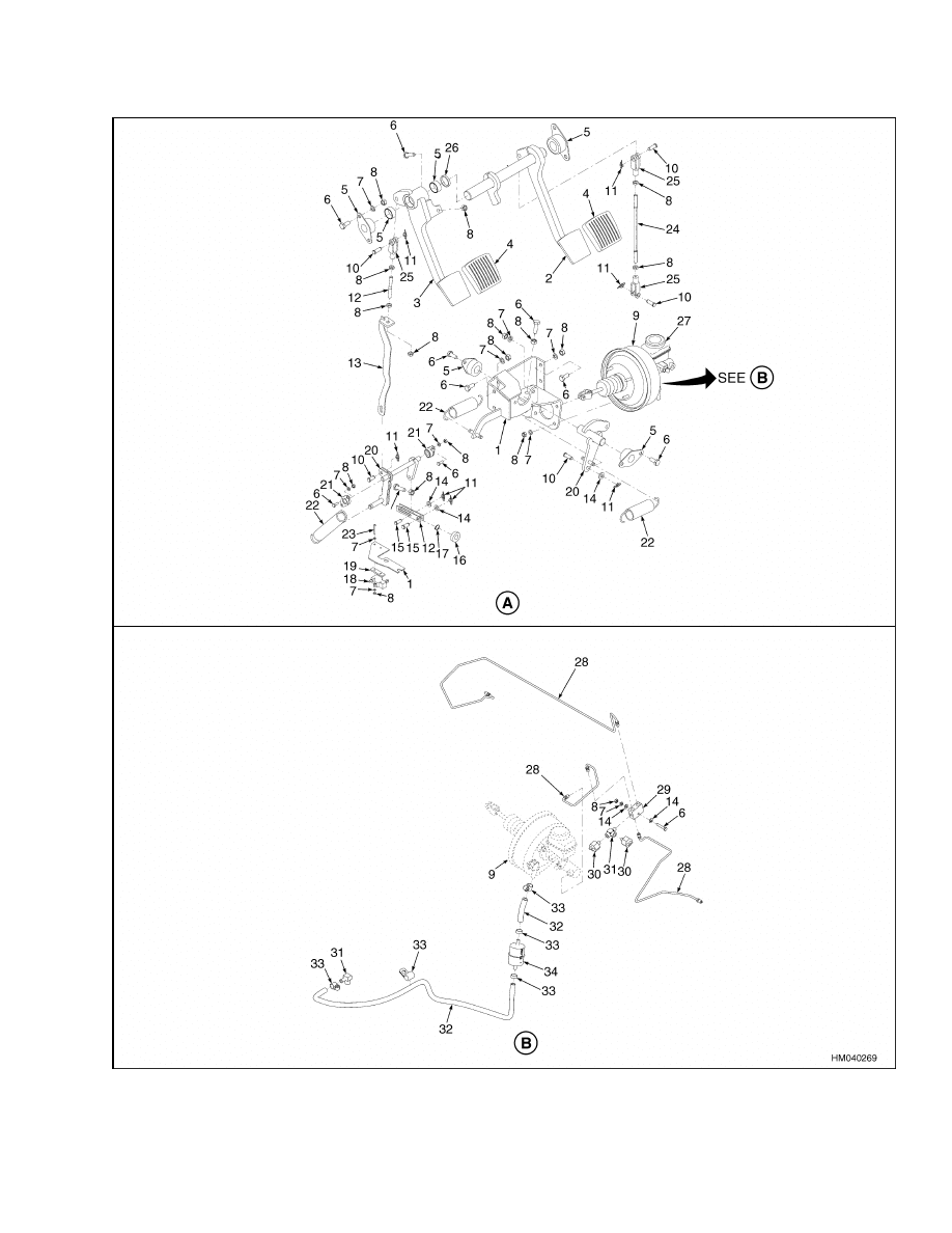
Figure 8. Brake System
9

Parking Brake Repair
1800 SRM 985
Legend for Figure 8
NOTE: DUAL-PEDAL OPTION SHOWN.
A. BRAKE SYSTEM ARRANGEMENT
B. BRAKE LINES ARRANGEMENT
1.
BRACKET
2.
BRAKE PEDAL
3.
INCHING PEDAL
4.
PEDAL PADS
5.
BUSHING
6.
CAPSCREW
7.
LOCKWASHER
8.
NUT
9.
MASTER CYLINDER AND BOOSTER
10. PIN
11. COTTER PIN
12. LINK
13. INCHING LINK
14. WASHER
15. ROD END PIN
16. DISK
17. SNAP RING
18. SWITCH
19. SPACER
20. CRANK
21. BEARING
22. SPRING
23. SCREW
24. HEX LINK
25. ROD END
26. WAVE SPRING
27. BRAKE FLUID RESERVOIR
28. BRAKE LINES
29. MANIFOLD
30. PRESSURE SWITCH
31. FITTING
32. HOSE
33. CLAMP
34. FILTER
Parking Brake Repair
REMOVE AND DISASSEMBLE
If the lever assembly for the parking brake must be
removed from the cowl, use the following procedure
(see Parking Brake Lever Adjustment):
1.
Place blocks under tires to make sure lift truck
cannot move. Push the release button to release
the parking brake lever.
2.
Remove the two nuts that fasten the parking
brake to the mounting bracket on the cowl. Re-
move the brake lever assembly.
3.
Loosen the jam nuts that fasten the threaded
ends of the brake cables to the brake lever as-
sembly.
4.
Turn adjuster knob counterclockwise until brake
cables are loosened. Disconnect cables from the
parking brake link.
5.
The service brake assembly must be removed be-
fore the parking brake cable can be removed from
the backplate of the service brake. The sheath
of the parking brake cable is threaded into the
backplate of the service brake.
ASSEMBLE AND INSTALL
If the lever assembly for the parking brake was re-
moved from the cowl, use the following procedure for
installation (see Figure 10):
1.
Make sure parking brake lever is in the released
position. Turn adjustment knob until parking
brake link is adjusted to the bottom of adjust-
ment slot.
2.
Place parking brake assembly between mounting
bracket on the inside of the cowl. Align mount-
ing holes on lever assembly with holes on mount-
ing bracket. Insert the two capscrews to secure
parking brake assembly to mounting bracket and
cowl.
3.
Install parking brake cable to parking brake
lever assembly by loosening grip and moving
yoke to lowest position.
4.
Check to ensure nut on parking cable end is at
the center in the screw range.
5.
Adjust guide to a distance of 12 mm (0.47 in.)
from the body guide. See dimension H in Fig-
ure 10.
6.
Install parking brake cable to yoke and guide.
10
1800 SRM 985
Parking Brake Repair
7.
Turn lever grip clockwise three times and pull
up yoke. Confirm that lever does not return by
pulling lever.
8.
Tighten the two bolts which fasten the guide and
tension the cables. Adjust guide to a distance
of 14 to 15 mm (0.55 to 0.59 in.) from the body
guide. See dimension H in Figure 10.
9.
Turn lever grip as needed to adjust it so that
parking brake will hold lift truck when applied.
1.
BRAKE BOOSTER
2.
SNAP RING
3.
SEAL
4.
PISTON
5.
SPRING
6.
CHECK VALVE
7.
SEAT
8.
O-RING
9.
MASTER CYLINDER
10. GROMMET
11. RESERVOIR
12. CAP
13. PIN
14. VACUUM FITTING
15. VACUUM LINES
16. CLAMPS
17. BRAKE BOOSTER FILTER
18. VACUUM LINE FITTING
Figure 9. Brake Booster and Master Cylinder
11
Parking Brake Adjustment
1800 SRM 985
Brake System Air Removal
Air must be removed from the brake fluid. Fill the
reservoir for the master cylinder with brake fluid.
Always remove air from master cylinder first, then
from wheel cylinders. Put one end of a rubber hose
on the special fitting at the master cylinder or wheel
cylinders. Put the other end of the hose in a container
with brake fluid. Loosen the special fitting. Push
slowly on the brake pedal. Close the special fitting.
Repeat the procedure until no air bubbles are seen in
the container. Check the fluid level in the reservoir.
Keep the reservoir full of brake fluid during these
procedures.
Brake Pedal Adjustment
The adjustment for the brake/inching pedal is in the section Single-Speed Powershift Transmission, Trou-
bleshooting and Repair 1300 SRM 397.
Parking Brake Adjustment
Make sure the service brakes are adjusted and the
operation of the automatic adjuster mechanism is
correct before the parking brake is adjusted.
1.
Turn adjustment knob to raise the parking brake
link and tighten parking brake cables. Turn ad-
justment knob until parking brakes are fully ap-
plied when lever is used to apply parking brake.
See Figure 10.
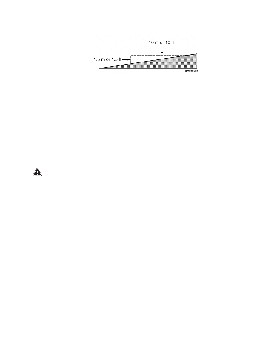
2.
Test the operation of the parking brake. The lift
truck with a capacity load must not move when
the parking brake is applied on a 15% grade, [a
slope that increases 1.5 m in 10 m (1.5 ft in 10 ft)].
See Figure 11.
3.
Check the operation of the switches on the park-
ing brake.
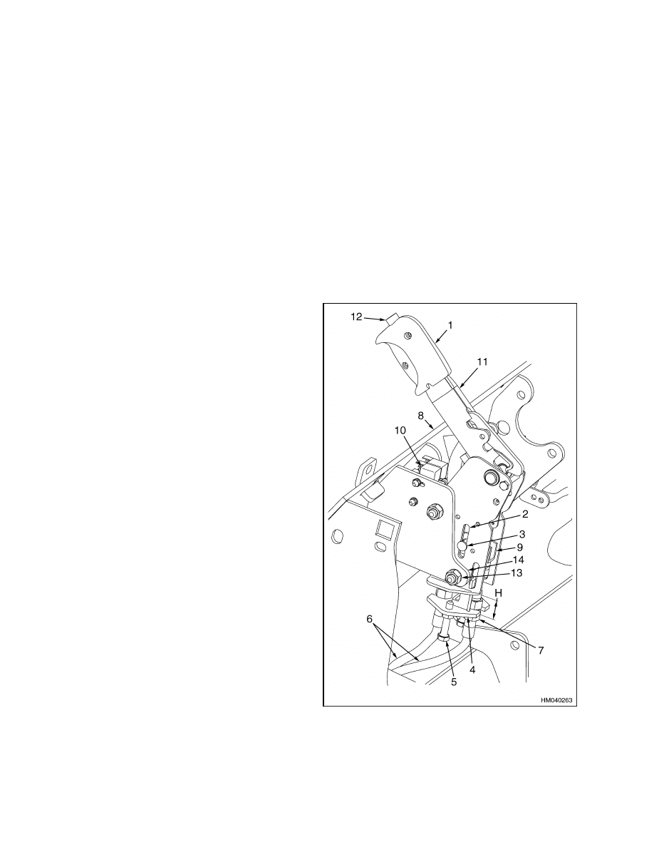
Legend for Figure 10
NOTE: THE LETTER H IN FIGURE ABOVE REP-
RESENTS THE GUIDE MOVEMENT RANGE. SEE
SECTION PARKING BRAKE REPAIR FOR H DIMEN-
SIONS.
1.
GRIP
2.
ADJUSTMENT
SLOT
3.
YOKE ASSEMBLY
4.
GUIDE PLATE
5.
ADJUSTMENT
KNOB
6.
PARKING BRAKE
CABLES
7.
NUTS
8.
COWL
9.
EQUALIZER LINK
10. MICROSWITCH
11. PARKING BRAKE
LEVER
12. RELEASE BUTTON
13. NUT
14. BRACKET
Figure 10. Parking Brake Lever Adjustment
12
1800 SRM 985
Parking Brake Switch Test (MONOTROL
®
Pedal Only)
Figure 11. Defining a 15% Grade
Parking Brake Not Applied Switch Test
The "Parking Brake Not Applied" switch is located
in the operator seat. This switch actuates an au-
dible buzzer on the instrument cluster. When the
operator leaves the seat for more than 2 seconds
without applying the parking brake, the buzzer
will be on continuously for 10 seconds. The buzzer
operates whether key switch is ON or OFF.
Parking Brake Switch Test (MONOTROL
®
Pedal Only)
When the parking brake assembly and cables have
been adjusted, the parking brake switches must be
tested for correct operation.
WARNING
If brake switches are not adjusted correctly,
the engine can be started with the parking
brake released. The purpose of the left-hand
switch is to prevent the starter motor from
being energized when parking brake is not ap-
plied. The right-hand switch de-energizes the
direction solenoids to put the transmission in
NEUTRAL when the parking brake is applied.
1.
Put lift truck on blocks so the drive wheels do
not touch the ground or any other object. Put
blocks at both sides of steering tires to prevent
movement of lift truck.
2.
Release parking brake. The right-hand, two-cir-
cuit microswitch closes the electric circuit for
the MONOTROL pedal (energize the solenoids
for the powershift transmission). The left-hand
switch de-energizes the starting circuit.
3.
Turn the ignition switch to the START position.
If parking brake switch operates correctly, the
starter will not energize. Turn ignition switch to
OFF position.
4.
Apply parking brake with the parking brake
lever. The right-hand, two-circuit microswitch
opens the MONOTROL circuit (de-energize the
solenoids for the transmission). The starting cir-
cuit is energized by the ignition switch through
the left-hand switch.
5.
Turn ignition switch to START position. The
starter operates when the parking brake switch
operates correctly. Turn ignition switch to OFF
position.
6.
Check the wires for the parking brake switches if
the conditions from the results of Step 2 through
Step 5 are not correct.
7.
Apply parking brake and start the engine. Push
parking brake lever toward the released position,
but do not push release button.
The parking
brake will stay in the ON position and locked.
8.
The transmission must be in NEUTRAL any
time the parking brake lever is applied. If re-
sults of the test are not correct, check for wear
and damage.
Make repairs as necessary and
13

Troubleshooting
1800 SRM 985
Brake Shoes Adjustment
The brake shoes are automatically adjusted when the
brakes are applied while the truck travels in RE-
VERSE. Use the procedure described below to man-
ually adjust the brakes after you make repairs.
1.
Put lift truck on blocks so drive wheels do not
touch the ground.
See the section Periodic
Maintenance 8000 SRM 987 for the correct
procedures. Make sure the blocks do not prevent
access to backplates of brakes.
2.
Remove plugs in slots in backplates. See Fig-
ure 3.
NOTE: If the automatic brake adjusters adjust the
brake shoes too much or too little, refer to Remove
and Disassemble in this section for the brake shoes.
3.
Use a tool for brake adjustment in the slot near-
est the teeth of the adjuster screw wheel. Push
up on the teeth and turn adjuster screw wheel
until brake shoes touch brake drum.
4.
Insert a small screwdriver through slot in back
plate in order to move automatic adjustment
lever away from adjuster screw wheel.
5.
Turn adjuster screw wheel with brake adjust-
ment tool. Push down on teeth to turn adjuster
screw wheel in opposite direction. Turn adjuster
screw wheel one revolution for the necessary
clearance between brake shoes and drum. Ro-
tate drive wheel to check for clearance.
6.
Repeat Step 3, Step 4, and Step 5 at other brake
assembly. Install plugs in backplates.
7.
Remove lift truck from blocks. Drive lift truck in
FORWARD and REVERSE. Use brakes to stop
10 times in each direction.
Troubleshooting
PROBLEM
POSSIBLE CAUSE
PROCEDURE OR ACTION
Brakes do not stop the lift
truck correctly.
Air is in the brake system.
Remove air from brake system.
Mount for the brake booster or the
brake booster is loose.
Tighten capscrews.
Brake shoes are worn or damaged.
Install new brake shoes.
Brake linings are too hard.
Install new brake shoes.
Brake drum is cracked.
Install new brake drum.
Backplate is damaged.
Install new backplate.
A wheel cylinder is leaking or does
not operate correctly.
Repair or install a new wheel cylin-
der.
Brake linings do not fit the brake
drums.
Install new brake shoes.
Master cylinder is damaged.
Repair or install a new master cylin-
der.
Water or oil is on the brake linings.
Clean linings or install new brake
shoes.
Brake booster is damaged.
Install a new brake booster.
14

1800 SRM 985
Troubleshooting
PROBLEM
POSSIBLE CAUSE
PROCEDURE OR ACTION
One brake does not release.
Brake shoe is damaged.
Install new brake shoes.
Return spring is damaged.
Install a new spring.
Brake lines have a restriction.
Install new brake lines.
Parking brake cable is damaged or
needs adjustment.
Adjust or install new brake cable(s).
Wheel cylinder is damaged.
Repair or install a new wheel cylin-
der.
Backplate is worn or damaged.
Install a new backplate.
Brakes make too much noise.
Oil, water, or brake fluid is on the lin-
ings.
Clean linings or install new brake
shoes.
Brake linings or brake shoes are
worn or damaged.
Install new brake shoes.
Brake drum is damaged.
Install a new brake drum.
Brakes
do
not
operate
equally.
Oil or brake fluid is on the linings.
Clean linings or install new brake
shoes.
Brake linings are worn or hard.
Install new brake shoes.
Wheel cylinder is leaking.
Repair or install a new wheel cylin-
der.
Brake shoes are not correctly in-
stalled.
Install brake shoes.
Backplate or brake shoes are dam-
aged.
Install new parts.
Brake drum is not round.
Repair or install a new brake drum.
Brake shoes are adjusted too tight.
Adjust brake shoes correctly.
Both brakes do not release.
Parking brake is not released.
Adjust parking brake.
Parking brake cables need adjust-
ment.
Adjust parking brake.
There is not enough clearance for the
push rod.
Adjust brake linkage.
15

Troubleshooting
1800 SRM 985
PROBLEM
POSSIBLE CAUSE
PROCEDURE OR ACTION
Both brakes do not release.
(Cont.)
Master cylinder is damaged.
Repair or install a new master cylin-
der.
Brake shoes are adjusted too tightly.
Adjust brake shoes.
Parking brake will not hold
the lift truck.
Oil, water, or brake fluid is on the lin-
ings.
Clean linings or install new brake
shoes.
Parking brake cables need adjust-
ment.
Adjust parking brake.
Parking brake cable is damaged.
Install new cable(s).
Parking brake will not re-
lease.
Parking brake lever is adjusted too
tightly.
Adjust parking brake.
Parking brake cables are damaged.
Install new cable(s).
16


TECHNICAL PUBLICATIONS
1800 SRM 985
5/05 (3/04)(9/03)(11/01) Printed in United Kingdom
Document Outline
- toc
- Brake System
- Safety Precautions Maintenance and Repair
- General
- Description and Operation
- Brake Shoe Assemblies Repair
- Brake Booster and Master Cylinder
- Parking Brake Repair
- Brake System Air Removal
- Brake Pedal Adjustment
- Parking Brake Adjustment
- Parking Brake Not Applied Switch Test
- Parking Brake Switch Test ( MONOTROL® Pedal Only)
- Brake Shoes Adjustment
- Troubleshooting
Wyszukiwarka
Podobne podstrony:
1466229 1800SRM0734 (05 2005) UK EN
897653 1800SRM0566 (04 2005) UK EN
1580505 0700SRM1123 (05 2005) UK EN
1565789 1800SRM1117 (08 2005) UK EN
1580506 0900SRM1124 (05 2005) UK EN
1529749 1800SRM1036 (08 2005) UK EN
1531815 1800SRM1040 (03 2005) UK EN
1580512 1600SRM1133 (05 2005) UK EN
1580526 8000SRM1151 (05 2005) UK EN
1580521 2200SRM1143 (05 2005) UK EN
1531821 1800SRM1037 (03 2005) UK EN
1598591 8000SRM1208 (05 2005) UK EN
897653 1800SRM0566 (04 2005) UK EN
więcej podobnych podstron