COOLING SYSTEM
S30FT, S35FT, S40FTS [E010];
H1.6FT, H1.8FT, H2.0FTS
(H30FT, H35FT, H40FTS) [F001];
S2.0-3.5FT (S40-70FT, S55FTS ) [F187];
H2.0-3.5FT (H40-70FT) [L177]
PART NO. 1580505
700 SRM 1123
SAFETY PRECAUTIONS
MAINTENANCE AND REPAIR
• When lifting parts or assemblies, make sure all slings, chains, or cables are correctly
fastened, and that the load being lifted is balanced. Make sure the crane, cables, and
chains have the capacity to support the weight of the load.
• Do not lift heavy parts by hand, use a lifting mechanism.
• Wear safety glasses.
• DISCONNECT THE BATTERY CONNECTOR before doing any maintenance or repair
on electric lift trucks. Disconnect the battery ground cable on internal combustion lift
trucks.
• Always use correct blocks to prevent the unit from rolling or falling. See HOW TO PUT
THE LIFT TRUCK ON BLOCKS in the Operating Manual or the Periodic Mainte-
nance section.
• Keep the unit clean and the working area clean and orderly.
• Use the correct tools for the job.
• Keep the tools clean and in good condition.
• Always use HYSTER APPROVED parts when making repairs. Replacement parts
must meet or exceed the specifications of the original equipment manufacturer.
• Make sure all nuts, bolts, snap rings, and other fastening devices are removed before
using force to remove parts.
• Always fasten a DO NOT OPERATE tag to the controls of the unit when making repairs,
or if the unit needs repairs.
• Be sure to follow the WARNING and CAUTION notes in the instructions.
• Gasoline, Liquid Petroleum Gas (LPG), Compressed Natural Gas (CNG), and Diesel fuel
are flammable. Be sure to follow the necessary safety precautions when handling these
fuels and when working on these fuel systems.
• Batteries generate flammable gas when they are being charged. Keep fire and sparks
away from the area. Make sure the area is well ventilated.
NOTE: The following symbols and words indicate safety information in this
manual:
WARNING
Indicates a condition that can cause immediate death or injury!
CAUTION
Indicates a condition that can cause property damage!
Cooling System
Table of Contents
TABLE OF CONTENTS
General ...............................................................................................................................................................
Cooling System Checks......................................................................................................................................
Exhaust Leaks Into Cooling System ............................................................................................................
Water Flow Restrictions in Radiator ............................................................................................................
Radiator Hoses...............................................................................................................................................
Water Pump ...................................................................................................................................................
Radiator Replacement .......................................................................................................................................
Cooling System, Clean...................................................................................................................................
Radiator, Remove...........................................................................................................................................
Radiator, Install .............................................................................................................................................
Fan Assembly Replacement ..............................................................................................................................
Remove ...........................................................................................................................................................
Inspect ............................................................................................................................................................
Install .............................................................................................................................................................
This section is for the following models:
S30FT, S35FT, S40FTS [E010];
H1.6FT, H1.8FT, H2.0FTS (H30FT, H35FT, H40FTS) [F001];
S2.0-3.5FT (S40-70FT, S55FTS ) [F187];
H2.0-3.5FT (H40-70FT) [L177]
©2005 HYSTER COMPANY
i

"THE
QUALITY
KEEPERS"
HYSTER
APPROVED
PARTS
700 SRM 1123
Cooling System Checks
General
This section contains the repair and replacement
instructions for the radiator, coolant level sensor, fan
assembly (puller type), fan shroud, coolant hoses,
coolant recovery bottle, and optional debris screen.
Cooling System Checks
EXHAUST LEAKS INTO COOLING SYSTEM
WARNING
During engine operation, be careful not to
touch the fan, pulleys, or drive belts. Contact
with these parts can cause serious injury.
To check for exhaust leaks into the cooling system,
use a Combustion Leak Test Kit for this purpose. Fol-
low the manufacturer’s instructions when doing the
test.
WATER FLOW RESTRICTIONS IN
RADIATOR
WARNING
During engine operation, be careful not to
touch the fan, pulleys, or drive belts. Contact
with these parts can cause serious injury.
To check for water flow restrictions in the radiator,
run engine until it is warm.
WARNING
The radiator or other parts of the cooling sys-
tem may be hot or under pressure and can
cause serious injury. Wait 30 minutes for the
radiator to cool. Do a touch test by touching
the radiator with your hand. If the radiator is
still hot to the touch, wait another 30 minutes
before attempting to check or fix any part of
the cooling system.
Shut engine OFF and feel the radiator. The temper-
ature must be even across the radiator. (The radiator
will be hotter near the top radiator hose.) Cold spots
on radiator indicate restrictions.
If radiator has leaks, either replace the radiator or
have it repaired by trained personnel.
RADIATOR HOSES
WARNING
The radiator or other parts of the cooling sys-
tem may be hot or under pressure and can
cause serious injury. Wait 30 minutes for the
radiator to cool. Do a touch test by touching
the radiator with your hand. If the radiator is
still hot to the touch, wait another 30 minutes
before attempting to check or fix any part of
the cooling system.
Inspect all radiator hoses. If they feel spongy or have
visible cracks, replace hoses.
WATER PUMP
WARNING
During engine operation, be careful not to
touch the fan, pulleys, or drive belts. Contact
with these parts can cause serious injury.
WARNING
The radiator or other parts of the cooling sys-
tem may be hot or under pressure and can
cause serious injury.
Run engine until it is warm. Check the operation of
water pump by holding the top radiator hose. If the
pump is operating, there will be pressure surges in
the hose.
Check for leaks around the timing belt cover near the
base of the oil pump.
Check the weep hole where water can drain by the oil
filter. If there is a drip, check the pump shaft seal and
water pump. Replacement of the pump shaft seal or
water pump may be necessary.
For repair procedures for the GM 2.4L water pump,
refer to the section GM Engine Repair, GM 2.4
Liter Engine 600 SRM 1121.
1
Radiator Replacement
700 SRM 1123
For repair procedures for the Mazda 2.0L and 2.2L
water pump, refer to the section Mazda Engine,
2.0L and 2.2L 600 SRM 1122.
For repair procedures for the Yanmar 2.6L and 3.3L
water pump, refer to the section Yanmar Diesel En-
gines 600 SRM 1205.
Radiator Replacement
COOLING SYSTEM, CLEAN
WARNING
Compressed air can move particles so that they
cause injury to the user or to other personnel.
Make sure the path of the compressed air is
away from all personnel. Wear protective gog-
gles or a face shield to prevent injury to the
eyes.
WARNING
The radiator fins on the radiator are very
sharp and can cause serious injury.
Wear
gloves while checking the radiator fins.
1.
Check radiator fins. Clean exterior of radiator
with compressed air or water as needed.
WARNING
DO NOT remove the radiator cap from the radi-
ator when the engine is hot. When the radiator
cap is removed, the pressure is released from
the system. If the system is hot, the steam and
boiling coolant can cause burns.
WARNING
The radiator or other parts of the cooling sys-
tem may be hot or under pressure and can
cause serious injury. Wait 30 minutes for the
radiator to cool. Do a touch test by touching
the radiator with your hand. If the radiator is
still hot to the touch, wait another 30 minutes
before attempting to check or fix any part of
the cooling system.
CAUTION
Disposal of lubricants and fluids must meet lo-
cal environmental regulations.
2.
Drain cooling system. Fill cooling system with
clean water. See the Radiator, Remove section
for more information.
3.
Install radiator cap. Run engine until top radia-
tor hose is hot. Stop engine and let engine cool.
4.
Drain water from radiator. If water is dirty, fill
system with water and repeat procedure until
water is clean.
CAUTION
Follow the manufacturer’s instructions when
using a chemical radiator cleaner.
5.
If water does not clean system, use a chemical
radiator cleaner.
CAUTION
Follow the manufacturer’s instructions when
using special equipment to reverse clean the
radiator.
6.
If radiator or cooling system is very dirty or
has a restriction, use reverse cleaning method.
This method uses water pressure to force water
through radiator in opposite direction of normal
flow.
CAUTION
Additives may damage the cooling system. Be-
fore using additives, contact your local Hyster
dealer.
7.
Fill cooling system with a mixture of 50 percent
water and 50 percent ethylene glycol boron free
antifreeze. The 50/50 mixture will protect cool-
ing system to
37 C ( 35 F). Add coolant as nec-
essary to keep level between the ADD and FULL
marks on the reservoir.
2
700 SRM 1123
Radiator Replacement
RADIATOR, REMOVE
WARNING
The radiator or other parts of the cooling sys-
tem may be hot or under pressure and can
cause serious injury. Wait 30 minutes for the
radiator to cool. Do a touch test by touching
the radiator with your hand. If the radiator is
still hot to the touch, wait another 30 minutes
before attempting to check or fix any part of
the cooling system.
1.
Turn OFF truck.
2.
Remove the hood and seat combination. See the
section Frame 100 SRM 1120.
WARNING
Always disconnect the cable at the negative
terminal first. Install a tag on the battery ter-
minals so that no one connects the cables on
the terminals.
3.
Disconnect the negative battery cable.
4.
Disconnect the positive battery cable.
WARNING
DO NOT remove the radiator cap from the radi-
ator when the engine is hot. When the radiator
cap is removed, the pressure is released from
the system. If the system is hot, the steam and
boiling coolant can cause burns.
5.
Let coolant cool to room temperature. Put a drain
pan under radiator. Remove radiator cap.
CAUTION
Disposal of lubricants and fluids must meet lo-
cal environmental regulations.
6.
Open the drain plug or disconnect the bottom ra-
diator hose.
7.
Cap radiator hoses.
8.
Disconnect hose to auxilary coolant reservoir and
remove reservoir.
9.
Remove battery and battery tray.
10. Disconnect electrical connector to the coolant
level sensor.
NOTE: For Mazda LPG engine, the LPG converter
bracket needs to be moved for clearance of radiator.
11. Remove screws from the radiator shroud and
move shroud out of the way.
12. Remove fan, fan spacer, and pulley.
13. Remove upper radiator bracket. See Figure 1.
14. Remove radiator from truck.
15. If necessary, remove the coolant level sensor.
RADIATOR, INSTALL
1.
If removed, install the coolant level sensor.
2.
Install radiator into truck.
3.
Install upper radiator bracket.
4.
Install fan, fan spacer, and pulley.
5.
Install the radiator shroud.
6.
Connect the electrical connector to the coolant
level sensor.
NOTE: For Mazda LPG engine, the LPG converter
bracket and screws must be installed to hold the con-
verter.
7.
Uncap radiator and reservoir ports and install
the auxiliary coolant reservoir.
8.
Connect the auxiliary coolant reservoir hose to
the radiator.
9.
Uncap the top radiator hose and connect the hose
to radiator.
10. Close the drain plug or install bottom radiator
hose.
3
Radiator Replacement
700 SRM 1123
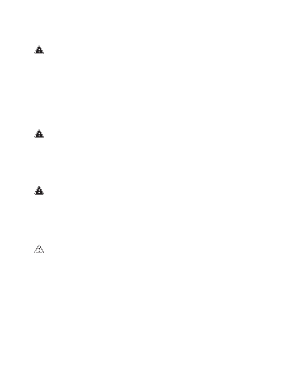
Figure 1. Cooling System
4
700 SRM 1123
Radiator Replacement
Legend for Figure 1
A. RADIATOR WITH EXTERNAL COOLER
B. RADIATOR WITH INTERNAL COOLER, MODINE SHOWN
1.
RADIATOR
2.
CAP
3.
UPPER HOSE
4.
LOWER HOSE
5.
CLAMP
6.
SHROUD
7.
CLIP
8.
WASHER
9.
SCREW
10. CLIP
11. UPPER BRACKET
12. CAPSCREW, S2.0-3.5FT (S40-70FT, S55FTS)
[F187]
13. INSERT
14. LOWER BRACKET, S2.0-3.5FT (S40-70FT,
S55FTS) [F187]
15. NUT-CLIP, S2.0-3.5FT (S40-70FT, S55FTS) [F187]
16. ISOLATOR
17. COOLANT LEVEL SENSOR
18. RESERVOIR
19. TUBE
20. OUTLET
21. HOSE
22. RESERVOIR OUTLET
23. CAP
24. BUSHING
25. SCREEN ASSEMBLY (OPTIONAL)
26. HEAT SHIELD
27. RESERVOIR BRACKET
28. HEAT SHIELD, H2.0-3.5FT (H40-70FT) [L177]
WARNING
Do not use an alcohol or methanol base an-
tifreeze. They are flammable and cause per-
sonal injury or damage to the lift truck.
CAUTION
Additives may damage the cooling system. Be-
fore using additives, contact your local Hyster
dealer.
11. Fill cooling system with a mixture of 50 percent
water and 50 percent ethylene glycol boron-free
antifreeze. The 50/50 mixture will protect cool-
ing system to
37 C ( 35 F).
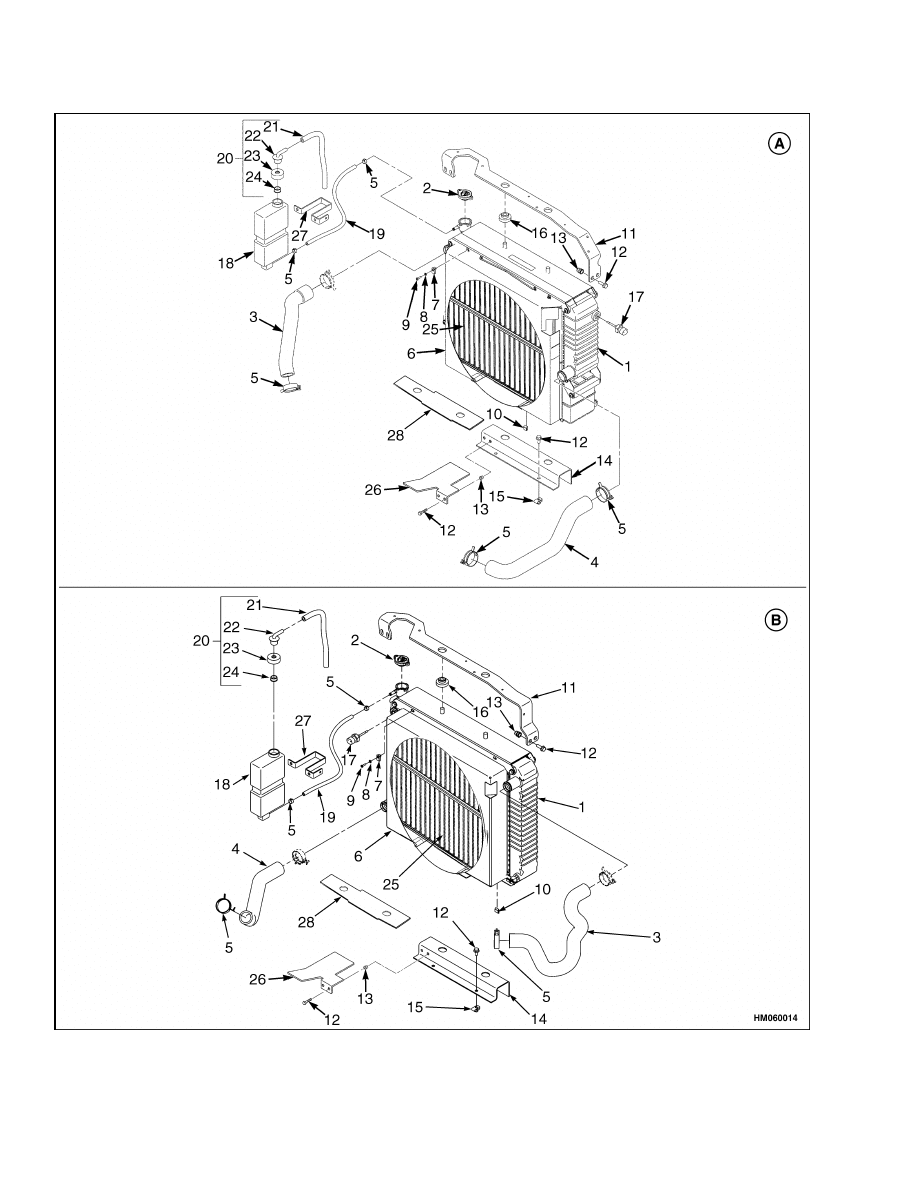
12. Use the same coolant mixture and fill the aux-
iliary coolant reservoir between the ADD and
FULL marks. See Figure 2.
13. Install battery and battery tray.
14. Connect the positive battery cable.
15. Connect negative battery cable.
Legend for Figure 2
1.
AUXILIARY COOLANT RESERVOIR
2.
ADD MARK
3.
FULL MARK
Figure 2. Auxiliary Coolant Reservoir
5
Fan Assembly Replacement
700 SRM 1123
16. Install the hood and seat combination. See the
section Frame 100 SRM 1120.
WARNING
During engine operation, be careful not to
touch the fan, pulleys, or drive belts. Contact
with these parts can cause serious injury.
WARNING
The radiator or other parts of the cooling sys-
tem may be hot or under pressure and can
cause serious injury.
17. Start and run engine until thermostat opens.
(The top radiator hose will be warm.)
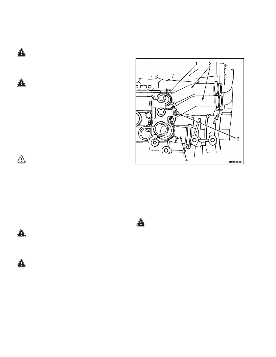
18. On lift trucks equipped with a GM 2.4L engine,
bleed air from the cooling system by opening the
bleed screw located on the left side behind the
alternator. When the air has been bled from the
system close the bleed screw. See Figure 3.
CAUTION
Additives may damage the cooling system. Be-
fore using additives, contact your local Hyster
dealer.
19. Check coolant level at the auxiliary coolant reser-
voir. Add coolant as necessary to keep level be-
tween the ADD and FULL marks on the reser-
voir.
1.
MANIFOLD
2.
COOLANT HOSES
3.
BLEED SCREW
4.
RADIATOR HOSE
Figure 3. Bleed Screw, GM 2.4L Engine
Fan Assembly Replacement
REMOVE
WARNING
During engine operation, be careful not to
touch the fan, pulleys, or drive belts. Contact
with these parts can cause serious injury.
WARNING
The radiator or other parts of the cooling sys-
tem may be hot or under pressure and can
cause serious injury. Wait 30 minutes for the
radiator to cool. Do a touch test by touching
the radiator with your hand. If the radiator is
still hot to the touch, wait another 30 minutes
before attempting to check or fix any part of
the cooling system.
WARNING
The radiator fins on the radiator are very
sharp and can cause serious injury.
Wear
gloves while removing fan assembly.
NOTE: The fan that is used is a puller type fan. Do
not replace with a pusher type fan.
1.
Turn OFF lift truck.
2.
If equipped, turn the LPG tank valve to the OFF
position.
3.
If equipped, release the LPG tank bracket and
swing tank away from the lift truck.
4.
Release the steering tilt latch and move the steer-
ing wheel forward.
5.
Release the seat latch and move the seat forward.
6
700 SRM 1123
Fan Assembly Replacement
6.
Release engine cover latch on engine cover and
swing engine cover up.
WARNING
To prevent a short circuit during fan belt re-
moval, disconnect the battery negative cable
at the battery negative terminal. Install a lock
or tag on the connector to prevent connection.
A tool could cause a short circuit, the high
current flow from the battery can cause an
injury or parts damage.
7.
Disconnect the negative battery cable from the
negative battery terminal.
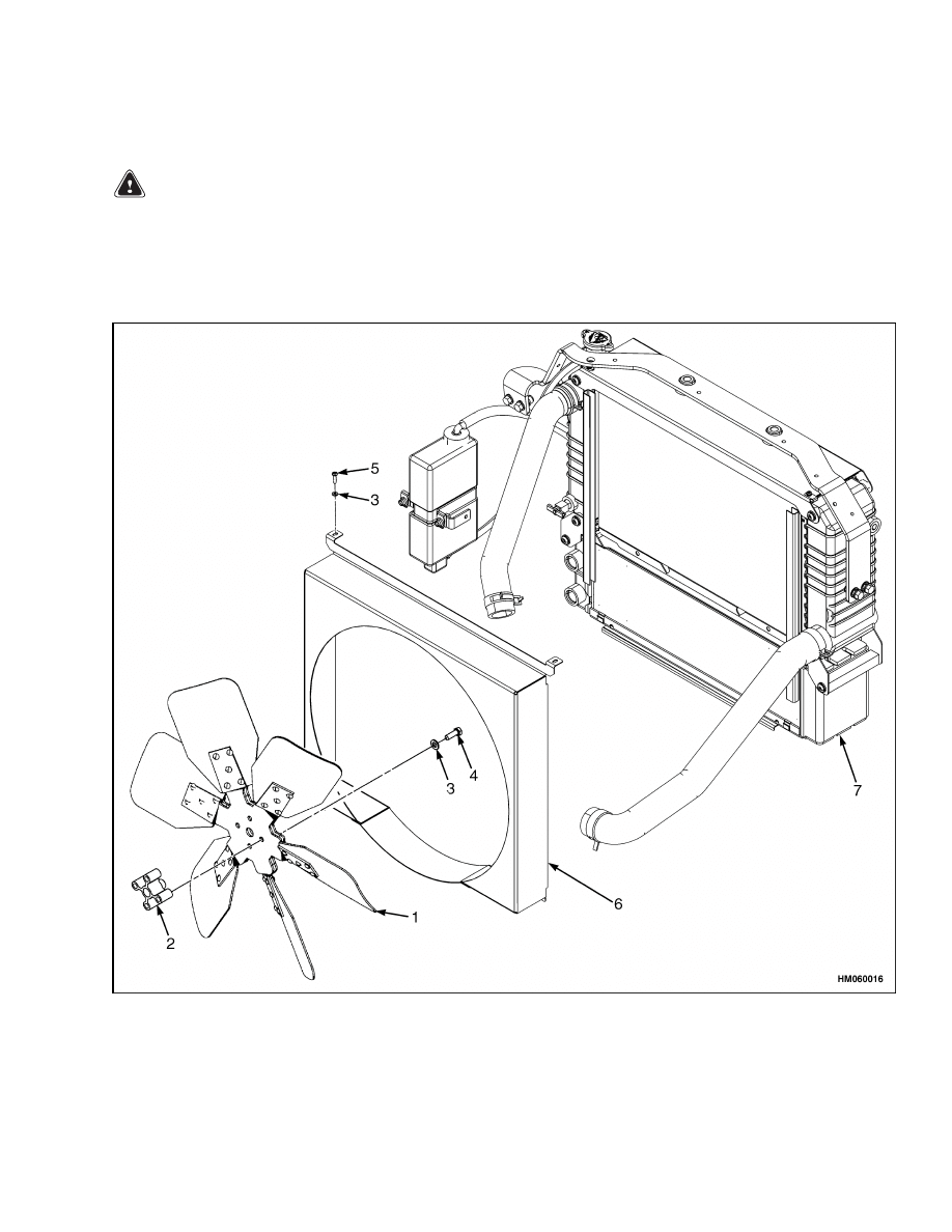
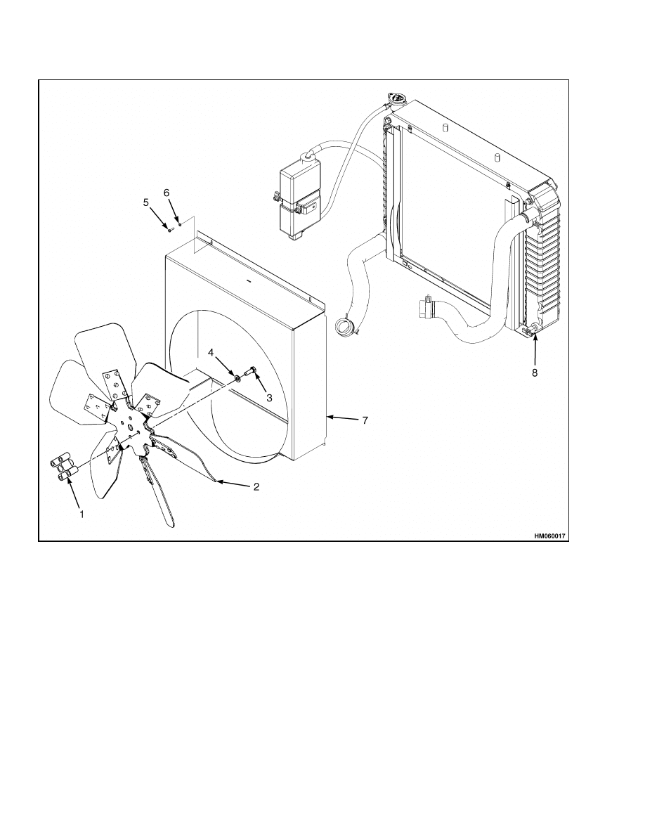
8.
Remove screws and washers from the radiator
shroud. For the GM 2.4L and Yanmar 2.6L and
3.3L, see Figure 4. For the Mazda 2.0L and 2.2L,
see Figure 5. Lean radiator shroud toward the
fan.
1.
FAN
2.
SPACER
3.
WASHER
4.
CAPSCREW
5.
SCREW
6.
RADIATOR SHROUD
7.
RADIATOR
Figure 4. GM 2.4L and Yanmar 2.6L and 3.3L Fan Removal
7
Fan Assembly Replacement
700 SRM 1123
1.
SPACER, H1.6FT, H1.8FT, H2.0FTS (H30FT,
H35FT, H40FTS) [F001] AND H2.0-3.5FT
(H40-70FT) [L177] LIFT TRUCKS ONLY
2.
FAN
3.
CAPSCREW
4.
WASHER
5.
SCREW
6.
WASHER
7.
RADIATOR SHROUD
8.
RADIATOR
Figure 5. Mazda 2.0L and 2.2L Fan Removal
8
700 SRM 1123
Fan Assembly Replacement
9.
For GM 2.4L and Yanmar 2.6L and 3.3L engines,
remove capscrews, washers, and spacer from the
fan pulley.
10. For H1.6FT, H1.8FT, H2.0FTS (H30FT, H35FT,
H40FTS) [F001] and H2.0-3.5FT (H40-70FT)
[L177] lift trucks with Mazda 2.0L and 2.2L
engines, remove capscrews, washers, and spacer
from the fan pulley.
11. For
S30FT,
S35FT,
S40FTS
(E010)
and
S2.0-3.5FT
(S40-70FT,
S55FTS)
[F187]
lift
trucks with Mazda 2.0L and 2.2L engines, re-
move the capscrews and washers retaining the
fan.
12. Remove the fan.
INSPECT
WARNING
DO NOT try to repair a damaged fan. If a fan
has a bent blade or is cracked, install a new fan.
A damaged fan can break during use and cause
damage or serious injury.
1.
Inspect the fan for any damage.
2.
If the fan is damaged, replace the entire fan.
INSTALL
WARNING
The radiator fins on the radiator are very
sharp and can cause serious injury.
Wear
gloves while installing fan assembly.
1.
Install the lower portion of the shroud in the re-
taining clips and lean the shroud toward the en-
gine.
2.
For the GM 2.4L and Yanmar 2.6L and 3.3L, in-
stall the spacer, washers, and capscrews to the
fan. Tighten the capscrews to 52 N•m (38 lbf).
See Figure 4.
3.
For H1.6FT, H1.8FT, H2.0FTS (H30FT, H35FT,
H40FTS) [F001] and H2.0-3.5FT (H40-70FT)
[L177] lift trucks with Mazda 2.0L and 2.2L en-
gines, install the spacer, washers, and capscrews
to the fan. Tighten the capscrews to 27 N•m
(20 lbf ft). See Figure 5.
4.
For
S30FT,
S35FT,
S40FTS
(E010)
and
S2.0-3.5FT
(S40-70FT,
S55FTS)
[F187]
lift
trucks with Mazda 2.0L and 2.2L engines, place
the fan in position and intsall capscrews and
washers.
Tighten the capscrews to 27 N•m
(20 lbf ft). See Figure 5.
5.
Lean the radiator shroud back toward the radia-
tor. Install the radiator shroud cover.
6.
Install the screws and washers and tighten.
7.
Reconnect the negative battery cable to the neg-
ative terminal of the battery.
8.
Pull engine cover down and re-latch with engine
cover latch.
9.
Move the seat back.
10. Release the steering wheel tilt latch and move
the steering wheel back.
11. If equipped, swing the LPG tank bracket back
toward the truck and re-latch.
12. If equipped, turn the LPG tank valve to the ON
position.
9

NOTES
____________________________________________________________
____________________________________________________________
____________________________________________________________
____________________________________________________________
____________________________________________________________
____________________________________________________________
____________________________________________________________
____________________________________________________________
____________________________________________________________
____________________________________________________________
____________________________________________________________
____________________________________________________________
____________________________________________________________
____________________________________________________________
____________________________________________________________
____________________________________________________________
____________________________________________________________
____________________________________________________________
____________________________________________________________
____________________________________________________________
10


TECHNICAL PUBLICATIONS
700 SRM 1123
5/05 (12/04) Printed in United Kingdom
Document Outline
- toc
Wyszukiwarka
Podobne podstrony:
1580506 0900SRM1124 (05 2005) UK EN
1568204 0700SRM1159 (08 2005) UK EN
1510466 1800SRM0985 (05 2005) UK EN
1580512 1600SRM1133 (05 2005) UK EN
1466229 1800SRM0734 (05 2005) UK EN
1580526 8000SRM1151 (05 2005) UK EN
1580521 2200SRM1143 (05 2005) UK EN
1597925 0700SRM1211 (03 2005) UK EN
1598591 8000SRM1208 (05 2005) UK EN
1568204 0700SRM1159 (08 2005) UK EN
więcej podobnych podstron