Interface Connector Specifications
Version 3.0
Interface Connector Electrical Specifications
<Introduction>
This guide provides information for developing peripherals to work with Sony CLIÉ(TM) handhelds
This guide describes the electrical specification for the devices connected to 18 pin connector of
the CLIÉ handhelds.
This specification applies to the following CLIÉ models:
PEG-NX series
PEG-NR series
PEG-T series
PEG-SJ series
PEG-SL series
Before using this guide, please take notice on the following.
<Trademark Ownership Information>
CLIÉ, Memory Stick and Jog Dial are trademarks of Sony Corporation
Palm Computing, Graffiti, HotSync are registered trademarks of Palm, Inc. and subsidiary companies of Palm in the
United States and other countries.
Palm OS is a registered trademark of Palm, Inc. in the United States.
Windows is a registered trademark of Microsoft Corporation in the United States and other countries.
All other trademarks are property of their respective owners.
<Notes>
Reproduction in whole or in part without written permission is prohibited.
All rights reserved.
Copyright 2002 Sony Corporation
Page 1 of 4
Interface Connector Specifications
Version 3.0
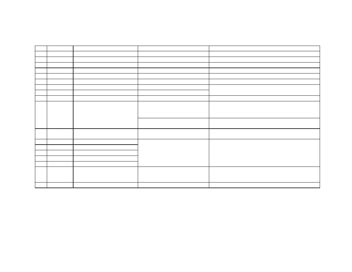
Interface Connector Specifications [Table 1]
No.
Signal Name Function
Specifications
Remarks
1
GND
Ground for signal/power supply
2
D+
USB Data+ signal
3
D-
USB Data- signal
4
SIG_GND
Ground for USB
5
VBUS
VBUS for USB
Connects to the power supplied by the USB host.
6
Reserved
7
DC+B
External power supply terminal
DC5.2±0.15V
8
CHARGE
Charging terminal
DC5.2±0.15V
9
Reserved
<Models except PEG-SL10>
5.5~3.4V (*Note 1) Max. 100mA
Peripherals communicate with the main unit under a stable
power supply with setting UNREG_OUT to 3.2V LDO. Refer
to "Serial I/F Schematic Example".
<PEG-SL10>
3.1±0.2V Max. 80mA
The supply capability decreases when the battery is getting
exhausted.
11 HOT_SYNC HotSync(R) interrupt terminal
active: L(GND)
inactive: open
12
DTR
"H" when UART is in use
13
RXD
UART RXD input
14
TXD
UART TXD output
15
CTS
UART CTS output
16
RTS
UART RTS input
17
CNT
Peripheral detection
Connect to the resistance between CNT
and the GND terminals as is shown in
Table 4 .
Do not supply any voltage to this pin from the peripheral side.
18
GND
Ground for signal/power supply
(*Note) 1. Desired value on design: 3.4 ~ 5.2V with the allowance ±0.3V. 3.4 ~ 4.2V if no AC adaptor is connected.
It can drop down to 3.1V when the battery gets exhausted. It remains below 3.4V at the
time the "low battery" warning shows up.
2. The actual number of physical pins on the CLIÉ connector is 20; the two most outside pins are unused.
For peripherals, if power is supplied to the CHARGE pin, it
must be supplied to the DC+B pin as well.
0-3.3V CMOS level
Refer to Table2, 3 for the details
10
UNREG_OUT
Provide unregulated power supply
(no link to the power button of the
main unit)
Copyright 2002 Sony Corporation
Page 2 of 4
Interface Connector Specifications
Version 3.0
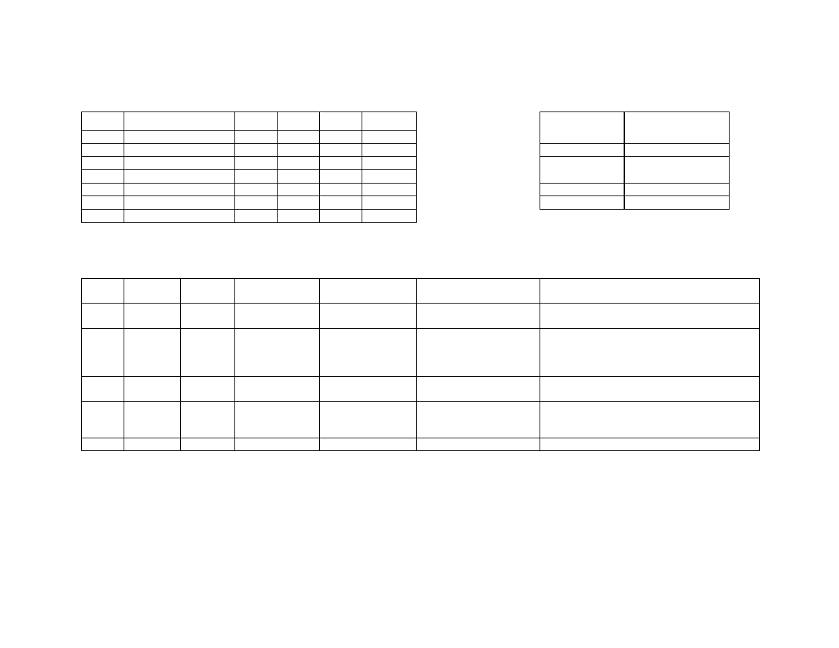
Input-output behavioral characteristics [Table2]
Resistance for Connection to CNT [Table 4]
Symbol
min.
max.
unit
V
IH
2.6
3.3
V
V
IL
0.0
0.4
V
|I
IN
|
100
µA
V
OH
2.1
3.3
V
V
OL
0.0
0.4
V
I
OH
2
mA
I
OL
-2
mA
*Notes
Use only the resistance values shown in this table.
UART Signals SpecificationsUART [Table3]
Number Signal Name Direction
12
DTR
Out
13
RXD
In
14
TXD
Out
15
CTS
In
16
RTS
Out
The main unit drives to L.
Specifications
H: open
L: close
Pulls up inside main
unit
Pulls up or pull down
inside main unit
The main unit drives to L.
Remarks
For the case of Sleeping
and/or UART not in use
The main unit drives to L.
At the side of peripherlas, set RXD to "Hi-Z" if
DTR=L. As it is connected to IrDA as well, main
unit may drive if DTR=L.. Peripherals are to be
driven by push/pull output.
As it is connected to IrDA as well, it may drive to H
even if DTR=L.
At the side of peripherlas, set CTS to "Hi-Z" if
DTR=L. Peripherals are to be driven by push/pull
output.
USB cable/cradle
Undocked
220
infinite ( > 10 Mohm)
Peripheral
Resistance (Kohm)
accuracy±1% or less
22
I
OH
=2mA
UART cable/cradle
UART
Modem/Cellular
47
I
OL
=-2mA
Condition
Hand Shaking
Function
Indicates that
UART is opened.
Receive Data
Transmit data
Hand Shaking
H level output voltage
L level output voltage
H level output current
L level output current
Description
H level input voltage
L level input voltage
Input leakage current
Copyright 2002 Sony Corporation
Page 3 of 4
Interface Connector Specifications
Version 3.0
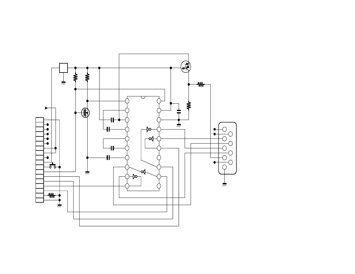
Serial I/F Schematic Example
1.
You may not distribute, transmit, or display the
circuit diagrams provided on this websit
("Diagrams") through network computer or by any
other media.
2.
This Diagram is provided "AS IS" without any
representation or warranty, either express or
implied, statutory or otherwise, including
warranties or representations with respect to the
accuracy, reliability, completeness, fitness for
particular purpose, non-infringement of third
parties rights, and any representations and
warranties relating thereto are expressly disclaimed.
This Diagram should be used at your own risk.
3.
Sony does not warrant the accuracy or
completeness of the information, text, graphics, or
other items contained in this Diagram. Sony may
make changes to this Diagram, at any time without
4.
Please refrain from asking any questions or making
inquiries concerning this Diagram.
*All Capacitors which aren't mentioned are 0.1uF.
All the capacity of Capacitor without the notation is 0.1uF(s).
1
2
3
4
20
19
18
17
5
6
7
8
9
10
16
15
14
13
12
11
1
2
3
4
5
6
7
8
9
10
11
12
13
14
15
16
17
18
1
2
3
4
5
6
7
8
9
I O
G
SIPEX
SP3222
22k
1%
100k
100k
1k
3.2V Reg.
low drop
0.1uF
To PC
with cross cable
RXD
RTS
TXD
CTS
DTR
DTR
RXD
TXD
CTS
RTS
5.2V
Copyright 2002 Sony Corporation
Page 4 of 4
Wyszukiwarka
Podobne podstrony:
Sony Ericsson GC79, TELEFONIA, Opisy telefonów
COMPACT DISK PLAYER MODEL SONY CDX GT212 CDX GT210
Fujitsu Siemens AMILO A1640 A1645 A1645G
DVD SONY DVP CX850D
Opis podlaczenia modulow S500 do sterownikow Siemensa
Ursus C25
IC Recorder SONY ICD XB800
Siemens, Mechanika i budowa maszyn, Semestr VI, Informatyka w eksploatacji pojazdów, Prezentacja
Siemens szkolenia SIMATIC 2010
C25
Kolorowy wyświetlacz graficzny z telefonu Siemens S65 M65 z kontrolerem Hitachi HD66773, cz 3
Fujitsu Siemens ESPRIMO Mobile v5535
GSM SIEMENS v 1 3 2
Fujitsu Siemens D1826 motherboard EN
Odblokowanie Sony Nowe
OBIEKTYWY kitowe do SONY ALFA, OBIEKTYWY DO SONY ALFA
SiemensKabel OP
więcej podobnych podstron