
DAEWOO M-150 BL2
SECTION 1D
ENGINE COOLING
CAUTION: Disconnect the negative battery cable before removing or installing any electrical unit or when a
tool or equipment could easily come in contact with exposed electrical terminals. Disconnecting this cable
will help prevent personal injury and damage to the vehicle. The ignition must also be in B unless otherwise
noted.
TABLE OF CONTENTS
Description and Operation
1D-2
. . . . . . . . . . . . . . . . . .
General Description
1D-2
. . . . . . . . . . . . . . . . . . . . . . .
Radiator
1D-2
. . . . . . . . . . . . . . . . . . . . . . . . . . . . . . . . . .
Surge Tank
1D-2
. . . . . . . . . . . . . . . . . . . . . . . . . . . . . . .
Coolant Pump
1D-3
. . . . . . . . . . . . . . . . . . . . . . . . . . . .
Thermostat
1D-3
. . . . . . . . . . . . . . . . . . . . . . . . . . . . . . .
Electric Cooling Fan
1D-3
. . . . . . . . . . . . . . . . . . . . . . .
Engine Coolant Temperature Sensor
1D-4
. . . . . . . . .
Coolant Temperature Sensor
1D-4
. . . . . . . . . . . . . . . .
Component Locator
1D-5
. . . . . . . . . . . . . . . . . . . . . . . .
Coolant Hose and Components
1D-5
. . . . . . . . . . . . .
Radiator/Fan
1D-6
. . . . . . . . . . . . . . . . . . . . . . . . . . . . . .
Diagnostic Information and Procedure
1D-7
. . . . . . .
Coolant Leaks Test
1D-7
. . . . . . . . . . . . . . . . . . . . . . . .
Surge Tank Cap Test
1D-7
. . . . . . . . . . . . . . . . . . . . . . .
Thermostat Test
1D-7
. . . . . . . . . . . . . . . . . . . . . . . . . . .
Cooling System Diagnosis
1D-8
. . . . . . . . . . . . . . . . . .
Repair Instructions
1D-9
. . . . . . . . . . . . . . . . . . . . . . . . .
On-Vehicle Service
1D-9
. . . . . . . . . . . . . . . . . . . . . . . . . .
Draining and Refilling the Cooling System
1D-9
. . . .
Surge Tank
1D-10
. . . . . . . . . . . . . . . . . . . . . . . . . . . . . .
Electric Cooling Fan
1D-11
. . . . . . . . . . . . . . . . . . . . . .
Radiator
1D-11
. . . . . . . . . . . . . . . . . . . . . . . . . . . . . . . . .
Thermostat (Typical)
1D-12
. . . . . . . . . . . . . . . . . . . . . .
Thermostat (Euro III)
1D-13
. . . . . . . . . . . . . . . . . . . . . .
Coolant Temperature Sensor
1D-14
. . . . . . . . . . . . . . .
Engine Coolant Temperature Sensor
1D-15
. . . . . . . .
Coolant Pump
1D-15
. . . . . . . . . . . . . . . . . . . . . . . . . . .
Specifications
1D-17
. . . . . . . . . . . . . . . . . . . . . . . . . . . .
General Specifications
1D-17
. . . . . . . . . . . . . . . . . . . .
Fastener Tightening Specifications
1D-18
. . . . . . . . . .
1D – 2 ENGINE COOLING
DAEWOO M-150 BL2
DESCRIPTION AND OPERATION
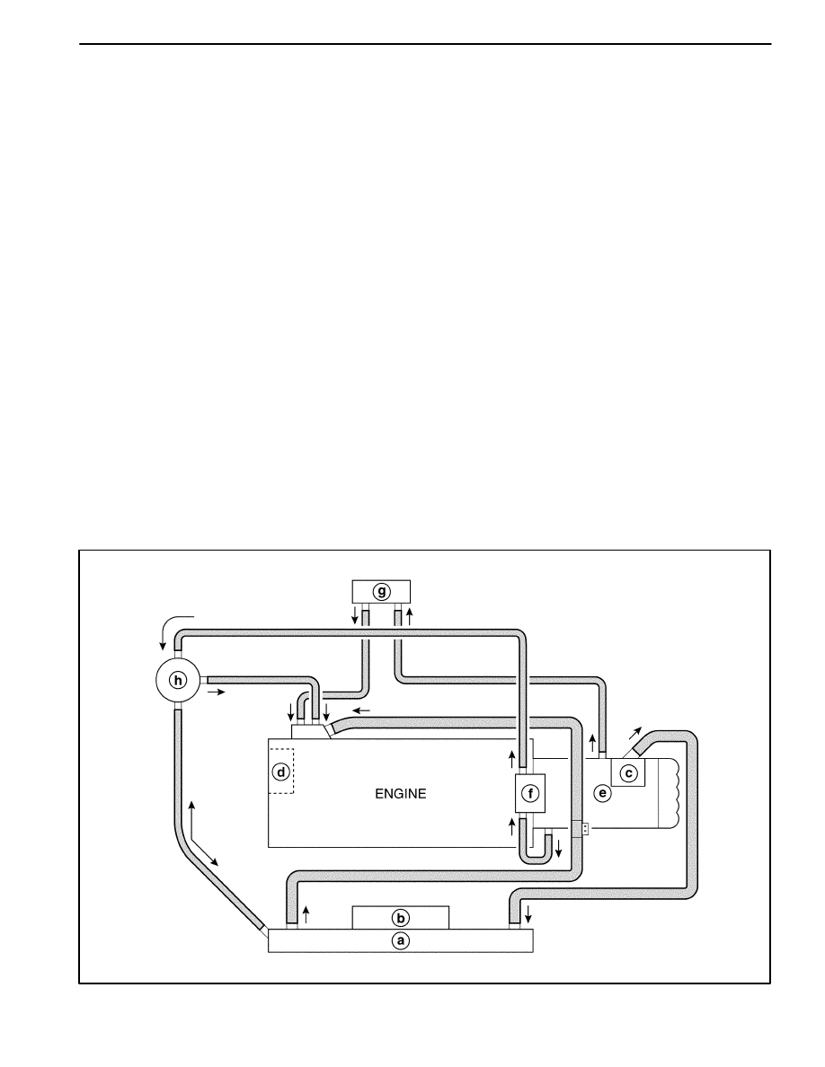
GENERAL DESCRIPTION
The cooling system maintains the engine temperature at
an efficient level during all engine operating conditions.
When the engine is cold the cooling system cools the
engine slowly or not at all. This slow cooling of the en-
gine allows the engine to warm up quickly.
The cooling system includes a radiator(a) and cooling
fan(b), a thermostat and housing(c), a coolant pump(d),
a coolant pump drive belt and coolant hose. The timing
belt drives the coolant pump.
All components must function properly in order for the
cooling system to operate. The coolant pump draws the
coolant from the radiator. The coolant then circulates
through water jackets in the engine block and the cylin-
der head, distributor case(e), throttle body(f). When the
coolant reaches the operating temperature of the ther-
mostat, the thermostat opens. The coolant then goes
back to the radiator where it cools.
This system directs some coolant through the hoses to
the heater core(g). This provides for heating and de-
frosting. The surge tank(h) is connected to the radiator
and throttle body to recover the coolant displaced by ex-
pansion from the high temperatures. The surge tank
maintains the correct coolant level.
The cooling system for this vehicle has no radiator cap
and drain cock. The coolant is added to the cooling sys-
tem through the surge tank. To drain the cooling system,
disconnect the lower radiator hose and drain the cool-
ant.
RADIATOR
This vehicle has a lightweight tube-and-fin aluminum ra-
diator.
SURGE TANK
The surge tank is a transparent plastic reservoir, similar
to the windshield washer reservoir.
The surge tank is connected to the radiator and throttle
body by a hose. As the vehicle is driven, the engine cool-
ant heats and expands. The portion of the engine cool-
ant displaced by this expansion flows from the radiator
into the surge tank. The air trapped in the radiator is de-
gassed into the surge tank.
When the engine is stops, the engine coolant cools and
contracts. The displaced engine coolant is then drawn
back into the radiator. This keeps the radiator filled with
the coolant to the desired level at all times and increases
the cooling efficiency.
Maintain the coolant level between the MIN and the
MAX marks on the surge tank when the system is cold.
D102D001
ENGINE COOLING 1D – 3
DAEWOO M-150 BL2
COOLANT PUMP
The belt-driven centrifugal coolant pump consists of an
impeller, a drive shaft, and a belt pulley.
The impeller is supported by a completely sealed bear-
ing.
The coolant pump is serviced as an assembly and,
therefore, cannot be disassembled.
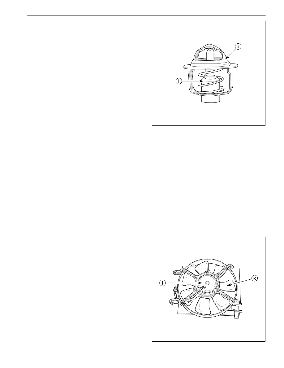
THERMOSTAT
A wax pellet-type thermostat controls the flow of the en-
gine coolant through the engine cooling system. The
thermostat(i) is mounted in the thermostat housing.
The thermostat stops the flow of the engine coolant from
the engine to the radiator in order to provide faster
warm-up, and to regulate the coolant temperature. The
thermostat remains closed while the engine coolant is
cold, preventing circulation of the engine coolant
through the radiator. At this point, the engine coolant is
allowed to circulate only throughout the heater core to
warm it quickly and evenly.
As the engine warms, the thermostat opens. This allows
the engine coolant to flow through the radiator, where
the heat is dissipated through the radiator. This opening
and closing of the thermostat permits enough engine
coolant to enter the radiator to keep the engine within
proper engine temperature operating limits.
The wax pellet in the thermostat is hermetically sealed in
a metal case(j). The wax element of the thermostat ex-
pands when it is heated and contracts when it is cooled.
As the vehicle is driven and the engine warms, the en-
gine coolant temperature increases. When the engine
coolant reaches a specified temperature, the wax pellet
element in the thermostat expands and exerts pressure
against the metal case, forcing the valve open. This al-
lows the engine coolant to flow through the engine cool-
ing system and cool the engine.
As the wax pellet cools, the contraction allows a spring
to close the valve.
The thermostat begins to open at 82
_
C (180
_
F) and is
fully open at 95
_
C (203
_
F). The thermostat closes at
80
_
C (176
_
F).
D102D002
ELECTRIC COOLING FAN
Caution: Keep hands, tools, and clothing away from
the engine cooling fans to help prevent personal in-
jury. This fan is electric and can turn ON whether or
not the engine is running.
Caution: If a fan blade is bent or damaged in any
way, no attempt should be made to repair or reuse
the damaged part. A bent or damaged fan assembly
should always be replaced with a new one.
The cooling fans are mounted behind the radiator in the
engine compartment. The electric cooling fans increase
the flow of air across the radiator fan and across the
condenser on air conditioner (A/C)-equipped vehicles.
This helps to speed cooling when the vehicle is at idle or
moving at low speeds.
D102D003
1D – 4 ENGINE COOLING
DAEWOO M-150 BL2
The main fan size is 320 mm (12.6 in.) in diameter with
seven blades(k) to aid the air flow through the radiator
and the condenser. An electric motor(l) attached to the
radiator support drives the fan.
A/C OFF or Non-A/C Model
D
The cooling fan is actuated by the electronic control
module (ECM) using a low speed cooling fan relay
and a high speed cooling fan relay. On A/C equipped
vehicles, a series/parallel cooling fan relay is also
used.
D
The ECM will turn the cooling fan on at low speed
when the coolant temperature reaches 93
_
C (199
_
F)
and high speed at 100
_
C (212
_
F).
D
The ECM will change the cooling fan from high speed
to low speed at 97
_
C (207
_
F) and turn the cooling
fans off at 90
_
C (194
_
F).
A/C ON
D
The ECM will only turn the cooling fan on at high
speed when the A/C system is on regardless of any
condition.
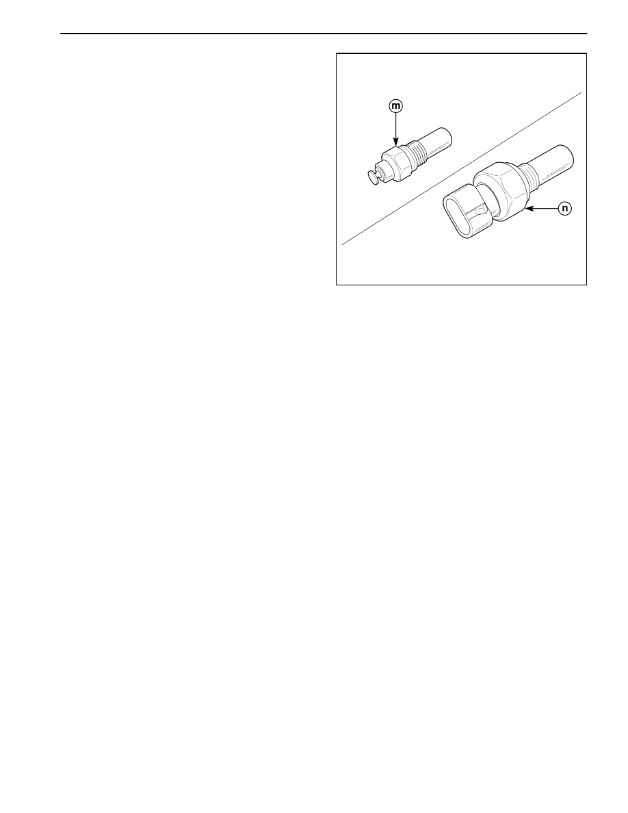
ENGINE COOLANT TEMPERATURE
SENSOR
The engine coolant temperature (ECT) sensor (n) uses
a thermistor to control the signal voltage to the engine
control module (ECM).
D102D004
COOLANT TEMPERATURE SENSOR
The coolant temperature sensor(m) controls the instru-
ment panel temperature indicator. The coolant tempera-
ture sensor is located on the distributor case with the
ECT sensor on an SOHC engine.
ENGINE COOLING 1D – 5
DAEWOO M-150 BL2
COMPONENT LOCATOR
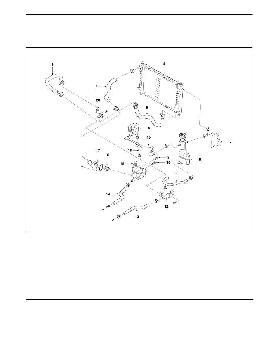
COOLANT HOSE AND COMPONENTS
D12D4011
1 Radiator Coolant Return Hose
2 Upper Radiator Hose
3 Not Used
4 Radiator Assembly
5 Lower Radiator Hose
6 Throttle Body Assembly
7 Surge Tank hose
8 Surge Tank
9 Coolant Temperature Sensor
10 Engine Coolant Temperature Sensor
11 Surge Tank Return Hose
12 Water Inlet Cap
13 Heater Outlet Hose
14 Heater Inlet Hose
15 Distributor Case
16 Thermostat
17 Thermostat Housing
18 Throttle Body Inlet Hose
19 Throttle Body Outlet Hose
20 Hose Bracket
1D – 6 ENGINE COOLING
DAEWOO M-150 BL2
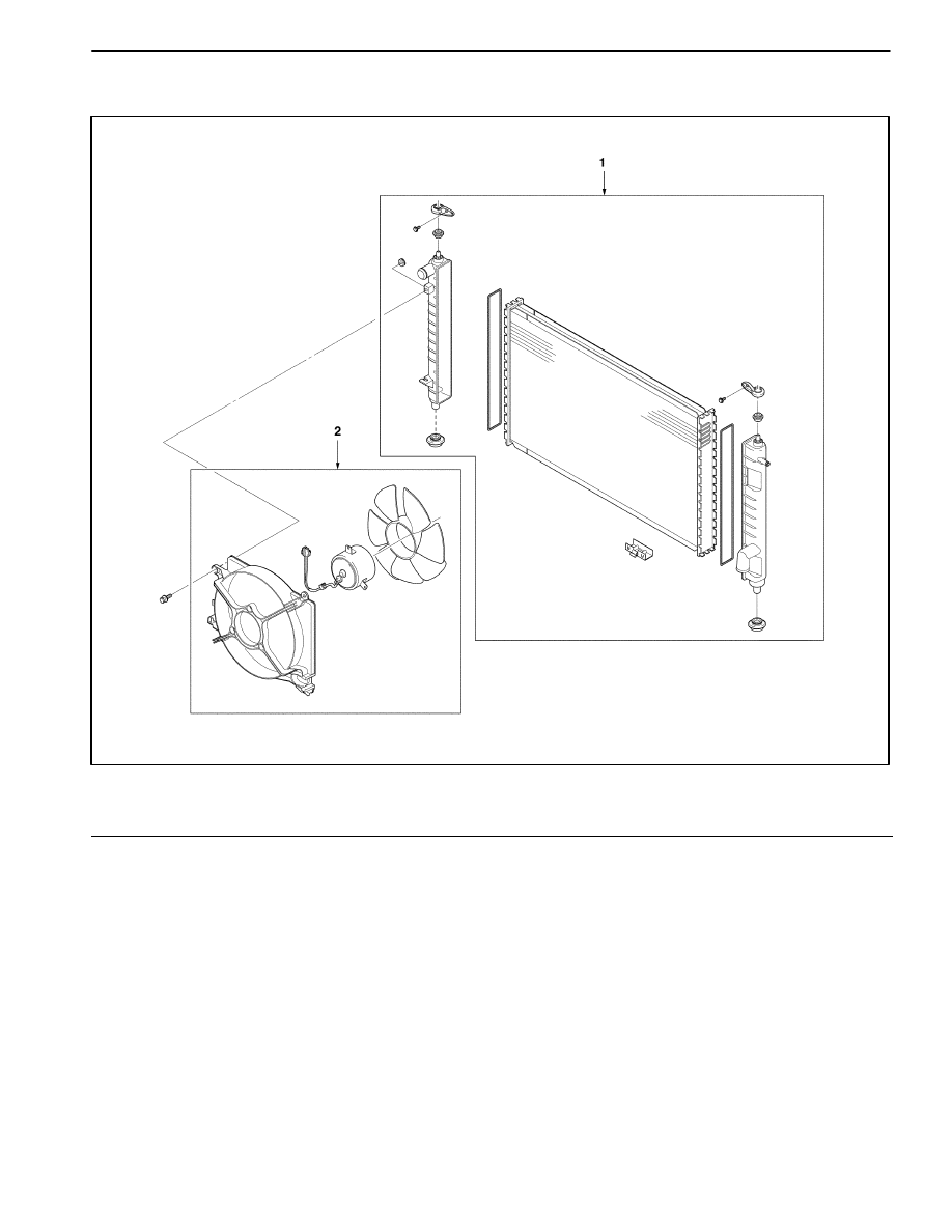
RADIATOR/FAN
D12D4021
1 Radiator Assembly
2 Electric Cooling Fan Assembly
ENGINE COOLING 1D – 7
DAEWOO M-150 BL2
DIAGNOSTIC INFORMATION AND PROCEDURE
COOLANT LEAKS TEST
1. Remove the surge tank cap after the engine cools.
2. Check the coolant level.
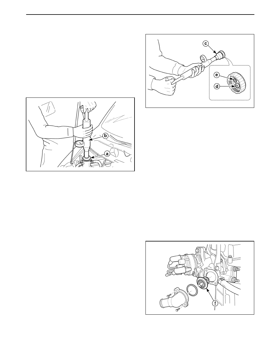
3. Install a suitable cooling system pressure tester(b) to
the surge tank filler neck using the adapter(a) and
pressurize (110–120 kPa (16.0–17.4 psi)).
4. Check the coolant leaks on the hoses and connec-
tions during 2 minutes.
5. If the leak is checked, replace the parts or repair the
connections.
D102D301
SURGE TANK CAP TEST
The surge tank cap(c) is equipped with the pressure
valve(d) and the vacuum valve(e). Therefore, the surge
tank cap maintains proper pressure. And The surge tank
cap protects the system from high-pressure by opening
a pressure valve, and protects the coolant hoses from
collapsing because of a vacuum.
1. Wash any sludge from the surge tank cap and the
valve seat of the vacuum pressure valve for the surge
tank cap.
2. Check for any damage or deformity to the vacuum
pressure valve for the surge tank cap. If any damage
or deformity is found, replace the cap.
3. Install a suitable cooling system pressure tester(b) to
the cap using the Adapter(a).
4. Pull the vacuum pressure valve to the open position.
If the surge tank cap does not seal properly, replace
the surge tank cap.
5. Pressurize the cap to 90 to 120kPa (13 to 17psi).
6. Wait 10 seconds and check the pressure held by the
tank cap tester.
7. If the pressure held by the cooling system pressure
tester falls below 80kPa (11.6psi) replace the surge
tank cap.
D102D302
THERMOSTAT TEST
1. Remove the thermostat(f) from the vehicle. Refer
to“Thermostat” in this section.
2. Make sure the valve spring is tight when the thermo-
stat is fully closed. If the spring is not tight, replace the
thermostat.
3. Suspend the thermostat and a thermometer in a pan
of 50/50mixture of ethylene glycol and water. Do not
let the thermostat or the thermometer rest on the bot-
tom of the pan because the uneven concentration of
heat on the bottom could result in inaccurate temper-
ature measurements.
4. Heat the pan on a burner.
5. Use the thermometer to measure the temperature of
the heated solution.
6. The thermostat should begin to open at 82
°
C (180
°
F)
and it should be fully open at 95
°
C (203.4
°
F) and it
should be fully close at 80
°
C (176.4
°
F). If it does not
open or close at these temperature, replace the ther-
mostat. Also, the thermostat rod’s stroke from the ini-
tially open to the fully open should be 8mm (0.31 in.).
D102D303

1D – 8 ENGINE COOLING
DAEWOO M-150 BL2
COOLING SYSTEM DIAGNOSIS
ÁÁÁÁÁÁÁÁÁÁ
ÁÁÁÁÁÁÁÁÁÁ
Condition
ÁÁÁÁÁÁÁÁÁÁÁÁÁ
ÁÁÁÁÁÁÁÁÁÁÁÁÁ
Probable Cause
ÁÁÁÁÁÁÁÁÁÁÁÁÁÁ
ÁÁÁÁÁÁÁÁÁÁÁÁÁÁ
Correction
Engine Overheats
D
A loss of the coolant.
D
Add the coolant.
D
A weak coolant solution.
D
Confirm that the coolant solution is a
50/50 mixture of ethylene glycol and
water.
D
Any dirt, any leaves, or any insects
on the front of the radiator.
D
Clean the front of the radiator.
D
The leakage from the hoses, the
coolant pump, the heater, the
thermostat housing, the radiator, the
heater core, or the head gasket.
D
Replace any damaged components.
D
A faulty thermostat.
D
Replace a damaged thermostat.
D
Retarded ignition timing.
D
Perform an ECM code diagnosis.
D
Confirm the integrity of the timing
belt.
D
An improperly operating electric
cooling fan.
D
Replace the electric cooling fan.
D
Plugged or rotted radiator hoses.
D
Replace any damaged radiator
hoses.
D
A faulty water pump.
D
Replace a faulty water pump.
D
A faulty surge tank cap.
D
Replace a faulty surge tank cap.
D
A cracked or plugged cylinder head
or engine block.
D
Repair the damaged cylinder head or
the damaged engine block.
D
A faulty radiator.
D
Replace a faulty radiator.
Loss of Coolant
D
A leak in the radiator.
D
Replace a damaged radiator.
D
A leak in the surge tank or the hose.
D
Replace the surge tank or the hose.
D
Looseness or damage of radiator
hoses, heater hoses, or connections.
D
Reseat the hoses.
D
Replace the hoses or the clamps.
D
Leaks in the coolant pump seal.
D
Replace the coolant pump seal.
D
Leaks in the coolant pump gasket.
D
Replace the coolant pump gasket.
D
An improper cylinder head torque.
D
Tighten the cylinder head bolts to
specifications.
D
Replace the cylinder head gasket, if
needed.
D
Leaks in the intake manifold, cylinder
head gasket, heater core.
D
Repair or replace any components,
as needed to correct the leak.
Engine Fails to Reach
Normal Operating
D
Thermostat to be stuck open or to be
wrong type.
D
Install a new thermostat of the
correct type and heat range.
Temperature or Cool Air
from the Heater
D
The coolant level below the MIN
mark on the surge tank.
D
Add sufficient coolant to raise the
fluid to the specified mark on the
surge tank.
ENGINE COOLING 1D – 9
DAEWOO M-150 BL2
REPAIR INSTRUCTIONS
ON–VEHICLE SERVICE
D12D5011
DRAINING AND REFILLING THE
COOLING SYSTEM
Caution: Do not remove the surge tank cap while
the engine and the radiator are hot. Scalding fluid
and steam may be blown out under pressure.
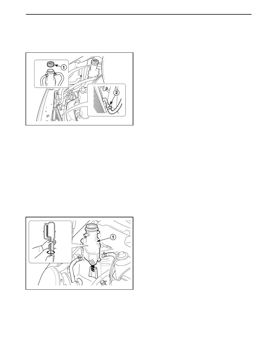
1. Place a pan below the vehicle to catch the draining
coolant.
2. Drain the coolant.
D
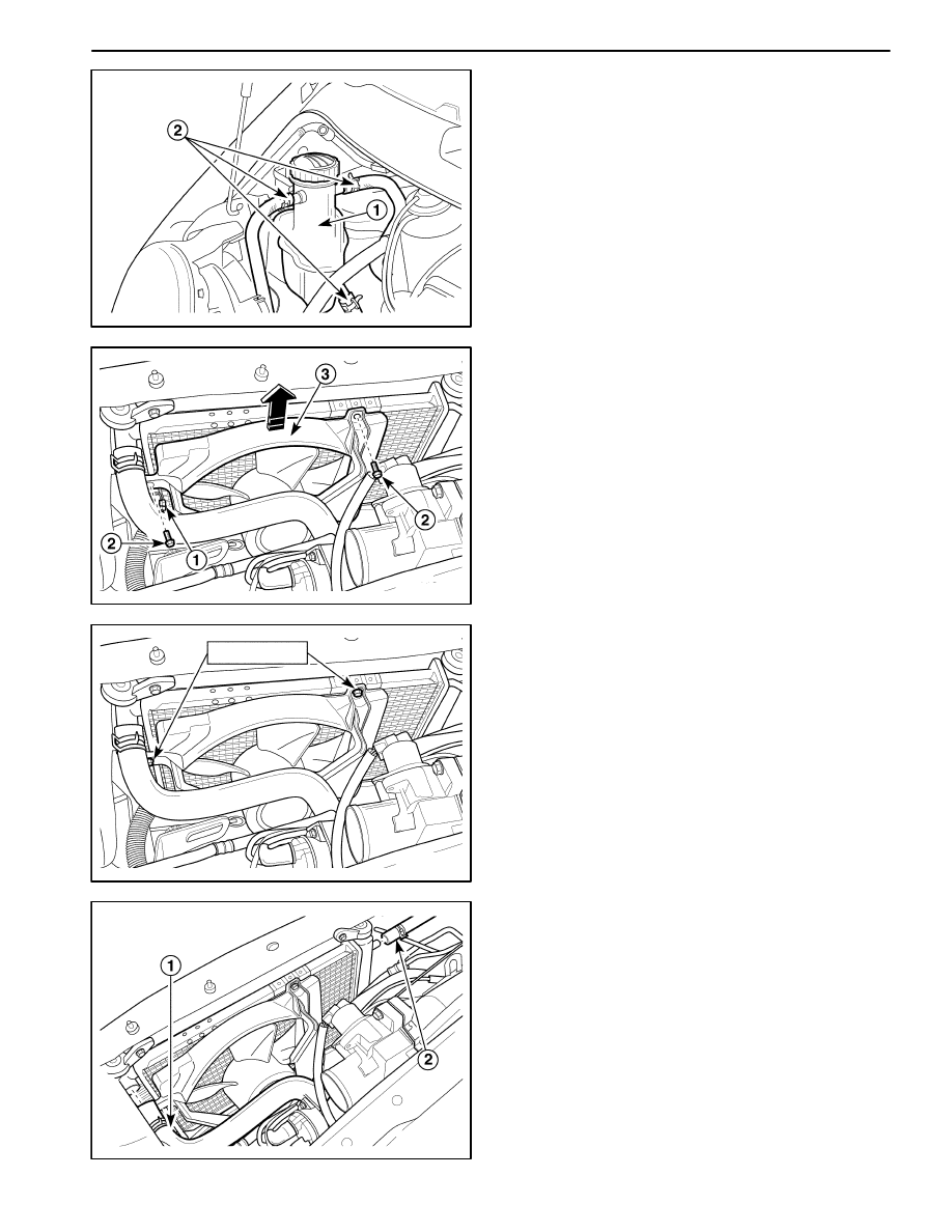
Remove the surge tank cap (1).
D
Disconnect the lower radiator hose (2).
Caution: Dispose of the used coolant to a used
coolant holding tank to be picked up with the used
oil for disposal. Never pour the used coolant down
the drain. Ethylene glycol antifreeze is an extremely
toxic chemical. Disposing of it into the sewer sys-
tem or the ground water can contaminate the local
environment.
D102D502
3. Connect the lower radiator hose.
4. Clean the cooling system.
D
Remove all sludge and dirt from inside the surge
tank. And install the surge tank. Refer to “Surge
Tank” in this section (1).
1D – 10 ENGINE COOLING
DAEWOO M-150 BL2
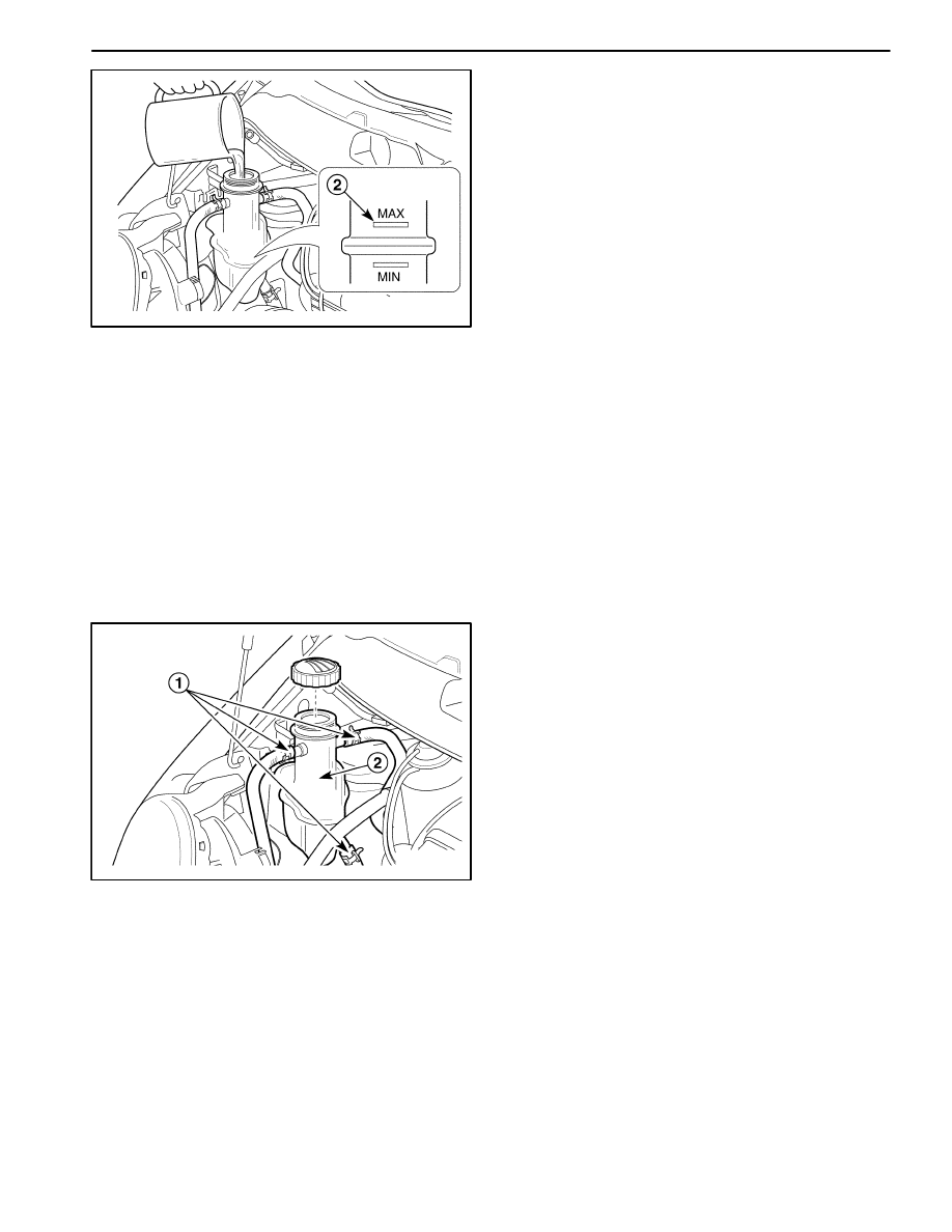
D102D503
D
Add the clean water to the surge tank (2).
5. Run the engine until the thermostat opens. You can
tell the thermostat is open when both radiator hoses
are hot to the touch.
6. Stop the engine and disconnect the lower radiator
hose to drain the coolant.
7. Repeat steps 3 through 6 until the drained water is
clear and free of coolant and rust.
Notice: Never use an antifreeze mixture more concen-
trated than 60 percent antifreeze to 40 percent water.
The solution freezing point increases above this con-
centration.
8. Fill the cooling system through the surge tank with a
mixture of ethylene glycol antifreeze and water. The
mixture must be at least 50 percent antifreeze, but
not more than 60 percent antifreeze for cold weather
operation.
9. Fill the surge tank to the specified MAX fill mark on
the outside of the tank.
10. Install the surge tank cap.
D102D504
SURGE TANK
Removal Procedure
Caution: To prevent personal injury, do not remove
the surge tank cap while the engine and the radiator
are hot, because the heat causes the system to re-
main under pressure scalding fluid and steam may
be blown out under pressure.
1. Drain the engine coolant to below the level of the
surge tank.
2. Remove the surge tank.
D
Loosen the overflow hose clamps and disconnect
the overflow hoses from the surge tank (1).
D
Remove the surge tank (2).
3. Clean the inside and the outside of the surge tank and
the surge tank cap with soap and water.
4. Rinse the surge tank and the cap thoroughly.
5. Check the surge tank and the cap for crack or other
damage.
ENGINE COOLING 1D – 11
DAEWOO M-150 BL2
D102D505
Installation Procedure
1. Install the surge tank to the vehicle.
D
Install the surge tank with pressing down (1).
D
Connect the overflow hoses to the surge tank (2).
2. Secure the overflow hoses to the surge tank with the
hose clamps.
3. Fill the surge tank with coolant to the MAX mark.
D102D506
ELECTRIC COOLING FAN
Removal Procedure
1. Disconnect the negative battery cable.
2. Remove the electric cooling fan assembly.
D
Disconnect the cooling fan electrical connector (1).
D
Remove the bolts (2).
D
Remove the electric cooling fan assembly (3).
3.5–4.5 N
S
m
D12D507A
Installation Procedure
1. Install the electric cooling fan assembly with the bolts.
Tighten
Tighten the bolts to 3.5–4.5 N
S
m (31–40 lb-in).
2. Connect the cooling fan electrical connector.
3. Connect the negative battery cable.
D12D5081
RADIATOR
Removal Procedure
1. Disconnect the negative battery cable.
2. Disconnect the lower radiator hose and drain the en-
gine cooling system. Refer to “Draining and Refilling
the Cooling System” in this section.
3. Disconnect the upper radiator hose and the surge
tank hose.
D
Loosen the upper radiator hose clamp and discon-
nect the upper radiator hose (1).
D
Loosen the surge tank hose clamp and disconnect
the surge tank hose (2).
1D – 12 ENGINE COOLING
DAEWOO M-150 BL2
D12D5091
4. Remove the electric cooling fan.
Refer to “Electric Cooling Fan” in this section.
5. Remove the radiator.
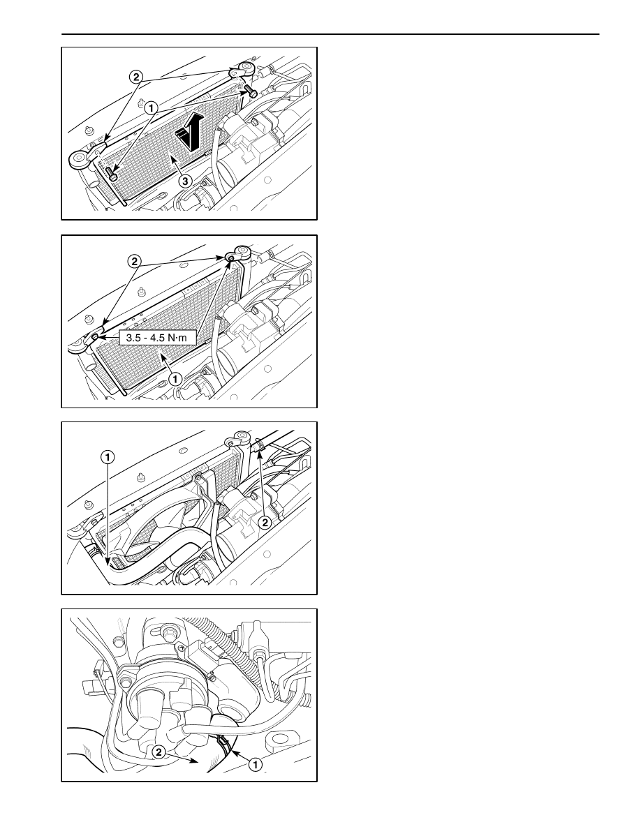
D
Remove the bolts (1).
D
Remove the radiator support brackets (2).
D
Remove the radiator (3).
6. Check the radiator for breaking, clog or other dam-
age.
Important: The radiator still contains a substantial
amount of coolant. Drain the remainder of the coolant
from the radiator into a drain pan.
D12D5101
Installation Procedure
1. Install the radiator with the mounting bolts (1) and the
support brackets (2).
Tighten
Tighten the support bracket bolts to 3.5–4.5 N
S
m
(31–40 lb-in).
2. Install the electric cooling fan.
Refer to “Electric Cooling Fan” in this section.
D12D5111
3. Connect the upper radiator hose to the radiator (1).
4. Connect the surge tank hose to the radiator (2).
5. Secure each hose with hose clamps.
6. Refill the engine cooling system. Refer to “Draining
and Refilling the Cooling System” in this section.
7. Connect the negative battery cable.
D102D512
THERMOSTAT (TYPICAL)
Removal Procedure
Caution: To prevent personal injury, do not remove
the surge tank cap while the engine and the radiator
are hot because the heat causes the system to re-
main under pressure. Scalding fluid and steam may
be blown out under pressure.
1. Remove air filter assembly. Refer to Section 1B,
SOHC Engine Mechanical.
2. Disconnect the lower radiator hose and drain the
coolant. Refer to “Drain and Refilling the Cooling Sys-
tem”
3. Disconnect the upper radiator hose.
ENGINE COOLING 1D – 13
DAEWOO M-150 BL2
D
Loosen the hose clamp (1).
D
Disconnect the upper radiator hose (2).
D102D513
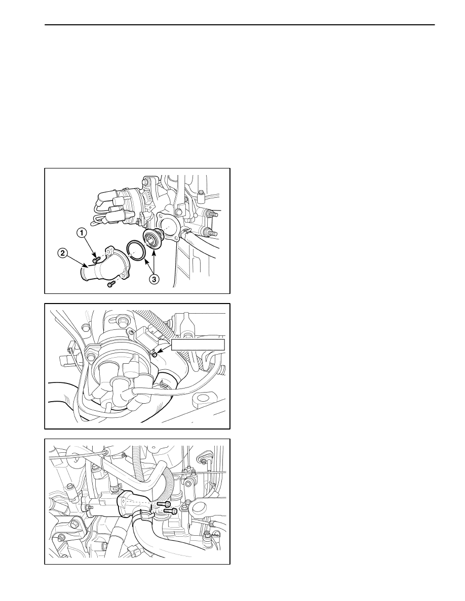
4. Remove the thermostat.
D
Remove the bolts (1).
D
Remove the thermostat housing (2).
D
Remove the thermostat with the gasket (3).
5. Check the gasket for crack or other damage.
6. Inspect the valve seat for foreign matter that could
prevent the valve from seating properly.
7. Inspect the thermostat for proper operation. Refer to
“Thermostat Test” in this section.
8–15 N
S
m
D12D514A
Installation Procedure
1. Install the thermostat with the bolts and the thermo-
stat housing.
Tighten
Tighten the mounting bolts to 8–15 N
S
m (71–130
lb-in).
2. Secure the upper radiator hose to the thermostat
housing with a hose clamp.
3. Refill the engine cooling system. Refer to “Draining
and Refilling the Cooling System” in this section.
MAA1D010
THERMOSTAT (EURO III)
Removal Procedure
Caution: To prevent personal injury, do not remove
the surge tank cap while the engine and the radiator
are hot because the heat causes the system to re-
main under pressure. Scalding fluid and steam may
be blown out under pressure.
1. Remove air filter assembly. Refer to Section 1B,
SOHC Engine Mechanical.
2. Disconnect the lower radiator hose and drain the
coolant. Refer to “Drain and Refilling the Cooling Sys-
tem”
3. Disconnect the upper radiator hose.
1D – 14 ENGINE COOLING
DAEWOO M-150 BL2
MAA1D020
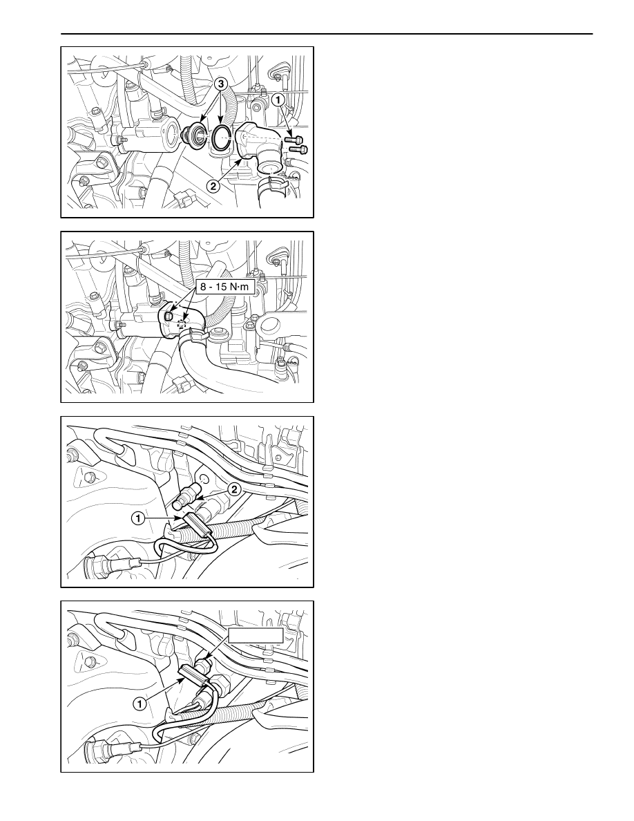
4. Remove the thermostat.
D
Remove the bolts.
D
Remove the thermostat housing.
D
Remove the thermostat with the gasket.
5. Check the gasket for crack or other damage.
6. Inspect the valve seat for foreign matter that could
prevent the valve from seating properly.
7. Inspect the thermostat for proper operation. Refer to
“Thermostat Test” in this section.
MAA1D011
Installation Procedure
1. Install the thermostat with the bolts and the thermo-
stat housing.
Tighten
Tighten the mounting bolts to 8–15 N
S
m (71–130
lb-in).
2. Secure the upper radiator hose to the thermostat
housing with a hose clamp.
3. Refill the engine cooling system. Refer to “Draining
and Refilling the Cooling System” in this section.
4. Install the air filter assembly. Refer to Section 1B,
SOHC Engine Mechanical.
D102D515
COOLANT TEMPERATURE SENSOR
Removal Procedure
1. Disconnect the negative battery cable.
2. Disconnect the lower radiator hose and drain the
coolant. Refer to “Draining and Refilling the Cooling
System” in this section.
3. Remove the coolant temperature sensor.
D
Disconnect the electrical connector (1).
D
Remove the coolant temperature sensor (2).
D12D516A
10 N
S
m
Installation Procedure
1. Install the coolant temperature sensor into the
threaded hole in the intake manifold.
Tighten
Tighten the coolant temperature sensor to 10 N
S
m
(89 lb-in).
D
Connect the electrical connector to the coolant
temperature sensor (1).
2. Connect the lower radiator hose and refill the coolant.
Refer to “Draining and refilling the cooling system” in
this section.
3. Connect the negative battery cable.
ENGINE COOLING 1D – 15
DAEWOO M-150 BL2
D102D517
ENGINE COOLANT TEMPERATURE
SENSOR
Removal Procedure
1. Disconnect the negative battery cable.
2. Disconnect the lower radiator hose and drain the
coolant “Draining and Refilling the Cooling System” in
this section.
3. Remove the engine coolant temperature (ECT) sen-
sor.
D
Disconnect the electrical connector (1).
D
Remove the ECT sensor (2).
D12D518A
20 N
S
m
Installation Procedure
1. Install the ECT sensor.
Tighten
Tighten the ECT sensor to 20 N
S
m (15 lb-ft).
D
Connect the electrical connector to the ECT sen-
sor (1).
2. Connect the lower radiator hose and refill the coolant.
Refer to “Draining and Refilling the Cooling System”
in this section.
3. Connect the negative battery cable.
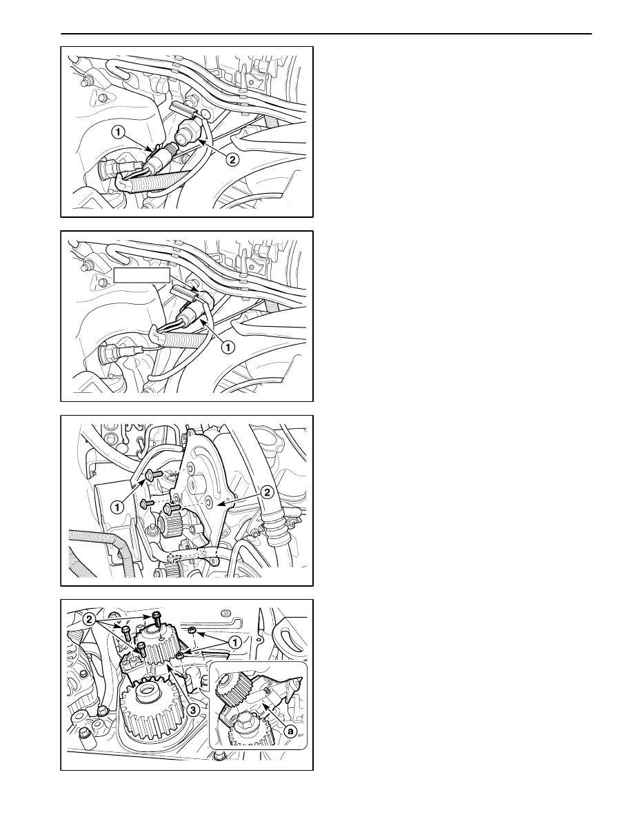
D102B533
COOLANT PUMP
Removal Procedure
1. Disconnect the negative battery cable.
2. Disconnect the lower radiator hose and drain the
coolant. Refer to “Draining and Refilling the Cooling
System” in this section.
3. Remove the timing belt. Refer to Section 1B, Engine
Mechanical.
4. Remove the rear timing belt cover.
D
Remove the bolts (1).
D
Remove the rear timing belt cover (2).
D102D519
5. Remove the coolant pump.
D
Remove the nuts (1).
D
Remove the bolts (2).
D
Remove the coolant pump (3).
D
Remove the gasket.
Notice: Remove the coolant pump as shown figure (a).
1D – 16 ENGINE COOLING
DAEWOO M-150 BL2
9–12 N
S
m
9–12 N
S
m
D12D520A
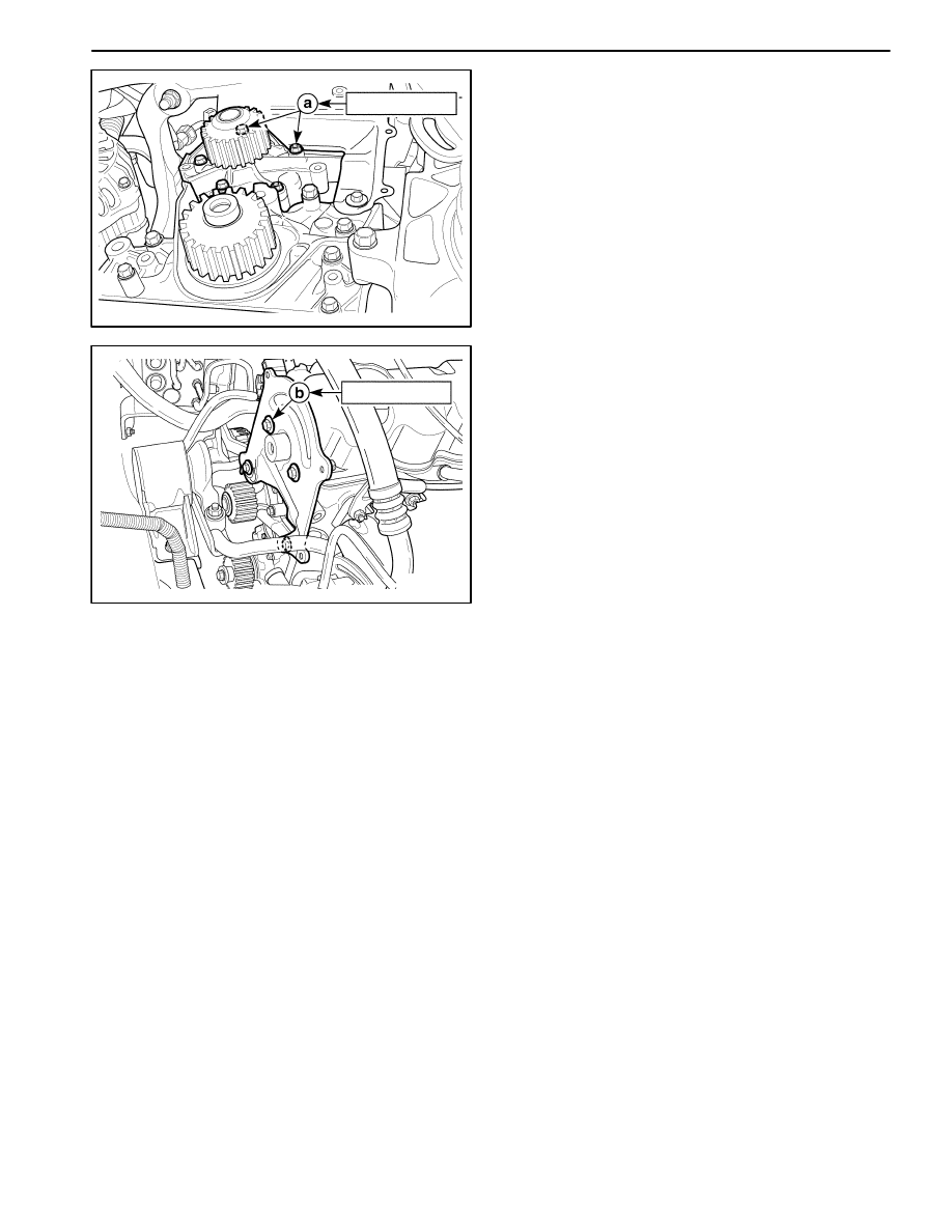
D12D521A
Installation Procedure
1. Install the coolant pump with the new gasket.
Tighten
Tighten the bolts and the nuts to 9–12 N
S
m (80–106
lb-in) (a).
2. Install the rear timing belt cover.
Tighten
Tighten the bolts to 9–12 N
S
m (80–106 lb-in) (b).
3. Install the timing belt. Refer to Section 1B, Engine
Mechanical.
4. Connect the lower radiator hose and drain the cool-
ant. Refer to “Draining and Refilling the Cooling Sys-
tem” in this section.
5. Connect the negative battery cable.

ENGINE COOLING 1D – 17
DAEWOO M-150 BL2
SPECIFICATIONS
GENERAL SPECIFICATIONS
Application
Description
Unit
Standard
Limit
Cooling
System
Cooling Type
–
Forced Water
Circulation
Coolant
Coolant Capacity
L/qt
3.8/4.00
Thermostat Type
–
Pellet Type
Temperature(opened initially)
°
C(
°
F)
82(180)
Thermostat
Temperature(perfectly opened)
°
C(
°
F)
95(203.4)
Temperature(perfectly closed)
°
C(
°
F)
80(176.4)
Stroke(perfectly opened)
mm(in.)
8 (0.32)
Cooling Fan Type
–
Electric
Blade Number
EA
6
Cooling Fan Diameter
mm(inch)
300(11.8)
Electric Cooling
Temperature At Low Speed ON
°
C(
°
F)
93(199.8)
Fan
Temperature At Low Speed OFF
°
C(
°
F)
90(194.4)
Temperature At High Speed ON
°
C(
°
F)
100(212.4)
Temperature At High Speed OFF
°
C(
°
F)
97(207)
Surge Tank
Open Pressure of The Pressure Valve
kPa (psi)
120–150
(17.4–21.8)
Surge Tank
Open Pressure of The Vacuum Valve
kPa (psi)
10 (1.5)
Water Pump Type
–
Centrifugal
Coolant Pump
Impeller Diameter
mm(in.)
60(2.36)
Impeller Blade Number
EA
7
Radiator Type
–
Cross–Flow
Core Width
mm(in.)
458(18.03)
Radiator
Core Height
mm(in.)
295(11.61)
Core Depth (Standard/Heavy Duty)
mm(in.)
16/27(0.63/1.06)
Resistance
(Coolant Temperature 50
°
C(122.4
°
F))
Ω
185.2
Coolant
Temperature
Resistance
(Coolant Temperature 85
°
C(185.4
°
F))
Ω
49.2
Sensor
Resistance
(Coolant Temperature 105
°
C(221.4
°
F))
Ω
27.5
Engine Coolant
Resistance
(Coolant Temperature 20
°
C(68.4
°
F))
Ω
3,520
Temperature
Sensor
Resistance
(Coolant Temperature 80
°
C(176.4
°
F))
Ω
332

1D – 18 ENGINE COOLING
DAEWOO M-150 BL2
FASTENER TIGHTENING SPECIFICATIONS
Application
N
S
m
Lb-Ft
Lb-In
Engine Coolant Temperature Sensor
10
–
89
Coolant Temperature Sensor
20
15
–
Coolant Pipe Bolt
8 – 15
–
71 – 130
Electric Cooling Fan Motor Nut
3.0 – 3.2
–
27 – 28
Electric Cooling Fan Assembly Bolt
3.5 – 4.5
–
31 – 40
Distributor Case Bolt/Nut
8 – 12
–
71 – 106
Radiator Mounting Bracket Bolt
3.5 – 4.5
–
31 – 40
Thermostat Housing Bolt
8 – 15
–
71 – 130
Water Inlet Cap Bolt
8 – 12
–
71 – 106
Coolant Pump Bolt/Nut
9–12
–
80 – 106
Coolant Pump Stud Bolt
9–12
–
80 – 106
Wyszukiwarka
Podobne podstrony:
engine cooling fan
03 Engine Cooling Heating System
ENGINE COOLING SECTION 1D 19
Automotive Engine Lubrication & Cooling Systems
3 04c Cooling engines test 2
ENGINE LUBRICATION & COOLING SYSTEM
Diesel engine, Akademia Morska -materiały mechaniczne, szkoła, Mega Szkoła, Szkoła moje
04 Engine
Mazda 6 (Mazda6) Engine Workshop Manual Mzr Cd (Rf Turbo)(3)
58 SPECIFICATIONS & ELECTRIC COOLING FANS
M31f1 Engine Controls 1 54
Engine Compartment 4 7
10 Engine Control System
Evaporative Cooling The Ceramic Refrigerator
Cooling
Computer engine control
ARTICLE MAINT INSPECTION ENGINE
więcej podobnych podstron