ENGINE LUBRICATION &
COOLING SYSTEMS
CONTENTS
QG
..................................3
Precautions ..................................................................3
LIQUID GASKET APPLICATION PROCEDURE
............3
Preparation ..................................................................3
........................................3
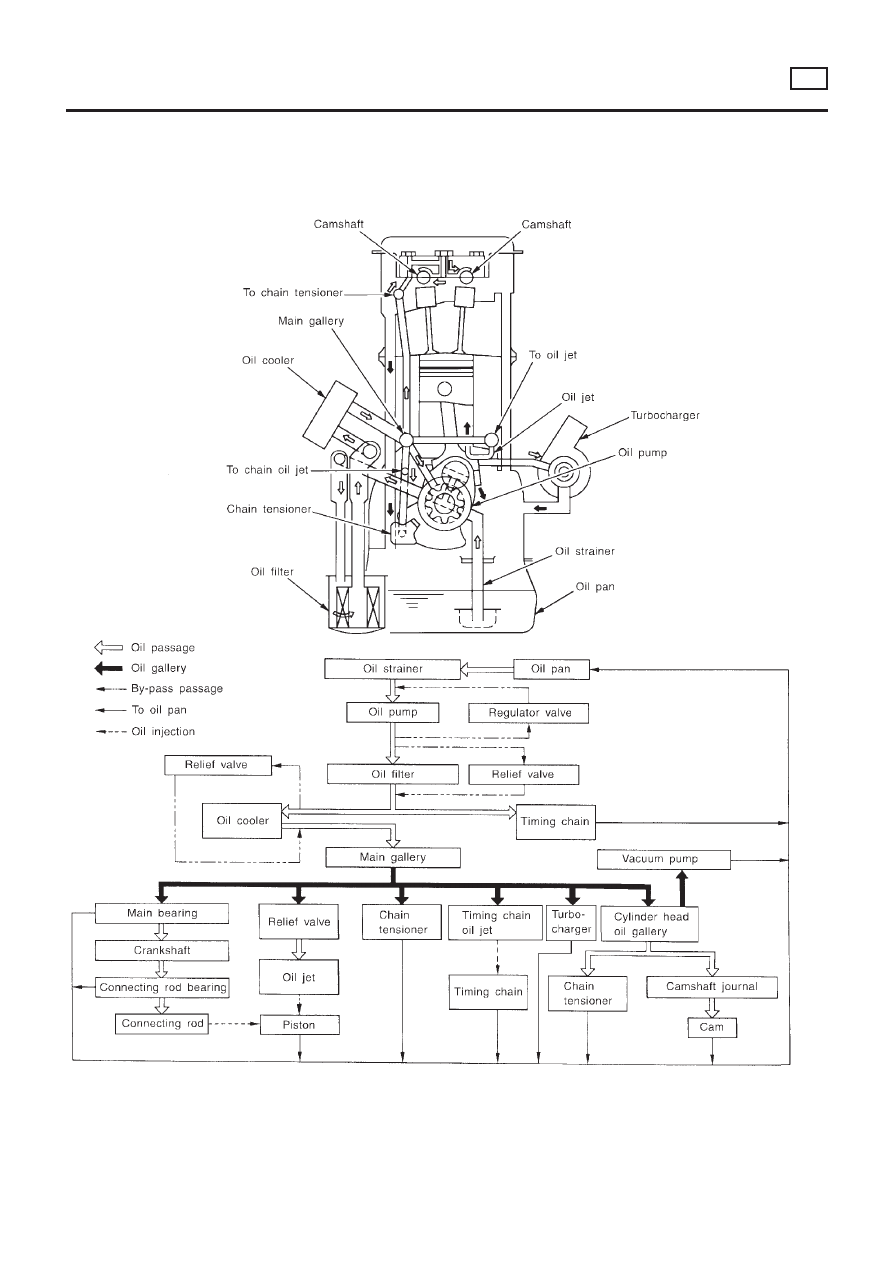
Lubrication Circuit ........................................................4
Oil Pressure Check......................................................5
Oil Pump ......................................................................5
.................................5
................................6
.............................................................7
............................7
Changing Engine Oil....................................................8
Changing Oil Filter.......................................................9
Service Data and Specifications (SDS).....................10
..........................................10
..........................................10
..........................10
........................................................10
........................................ 11
Precautions ................................................................ 11
LIQUID GASKET APPLICATION PROCEDURE
.......... 11
Preparation ................................................................ 11
...................................... 11
Cooling Circuit ...........................................................12
System Check............................................................12
...................12
............................................13
....................................13
CHECKING COOLING SYSTEM FOR LEAKS
............13
Water Pump ...............................................................14
...............................14
...........................................................14
Thermostat.................................................................15
...............................15
...........................................................16
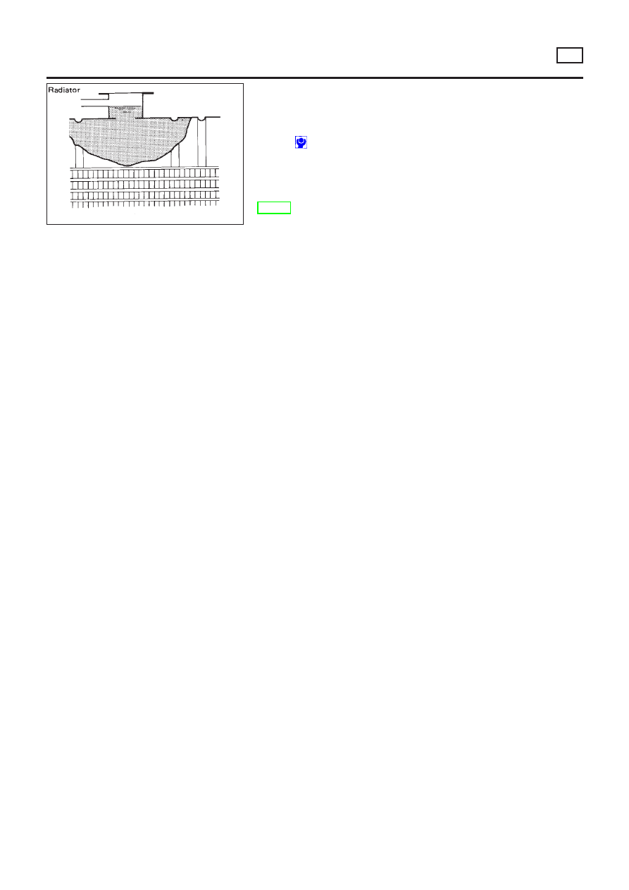
Radiator .....................................................................17
.......................................................17
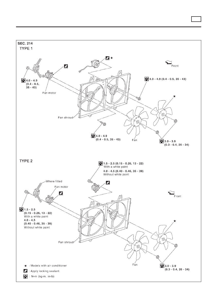
Cooling Fan ...............................................................18
.......................................................18
................................................19
Changing Engine Coolant..........................................19
............................19
...........................20
............................20
Overheating Cause Analysis .....................................21
Service Data and Specifications (SDS).....................22
........................................................22
..............................................................22
..............................................22
SR
................................23
Precautions ................................................................23
LIQUID GASKET APPLICATION PROCEDURE
..........23
Preparation ................................................................23
......................................23
Lubrication Circuit ......................................................24
Oil Pressure Check....................................................25
Oil Pump ....................................................................25
...............................25
..............................26
...........................................................26
..........................27
Changing Engine Oil..................................................28
Changing Engine Oil Filter ........................................28
Oil Filter .....................................................................29
Oil Cooler...................................................................29
...............................29
...........................................................30
Service Data and Specifications (SDS).....................30
..........................................30
..........................30
..........................................30
........................................................30
........................................31
Precautions ................................................................31
LIQUID GASKET APPLICATION PROCEDURE
..........31
Preparation ................................................................31

........................................31
Cooling Circuit ...........................................................32
System Check............................................................32
...................32
CHECKING COOLING SYSTEM FOR LEAKS
............32
............................................33
....................................33
Water Pump ...............................................................33
...............................33
...........................................................34
Thermostat.................................................................35
...............................35
...........................................................36
Water Outlet...............................................................36
...........................................................36
........................................................36
Radiator .....................................................................37
.......................................................37
Cooling Fan Control System .....................................37
Changing Engine Coolant..........................................38
............................38
...........................38
............................39
Overheating Cause Analysis .....................................40
Service Data and Specifications (SDS).....................41
........................................................41
..............................................................41
..............................................41
YD
................................42
Precautions ................................................................42
LIQUID GASKET APPLICATION PROCEDURE
..........42
Preparation ................................................................42
......................................42
Lubrication Circuit ......................................................43
Oil Pressure Check....................................................44
Oil Pump ....................................................................44
...............................44
..............................45
..........................................45
..........................46
Changing Engine Oil..................................................47
Oil Filter Bracket ........................................................48
...............................48
Changing Oil Filter.....................................................48
...............................................................49
........................................................49
Oil Cooler...................................................................50
...............................50
Service Data and Specifications (SDS).....................51
..........................................51
..........................51
..........................................51
...........................................51
........................................52
Precautions ................................................................52
LIQUID GASKET APPLICATION PROCEDURE
..........52
Preparation ................................................................52
......................................52
Cooling Circuit ...........................................................53
System Check............................................................54
...................54
............................................54
....................................54
CHECKING COOLING SYSTEM FOR LEAKS
............55
Water Pump ...............................................................55
...............................55
...............................................................56
...........................................................56
........................................................56
Thermostat.................................................................57
...............................57
...........................................................58
Radiator .....................................................................58
.......................................................58
...............................59
Cooling Fan ...............................................................59
.......................................................59
................................................59
Changing Engine Coolant..........................................59
............................59
...........................60
............................61
Overheating Cause Analysis .....................................62
Service Data and Specifications (SDS).....................63
........................................................63
..............................................................63
................................63
CONTENTS
(Cont’d)
LC-2
SEM164F
AEM080
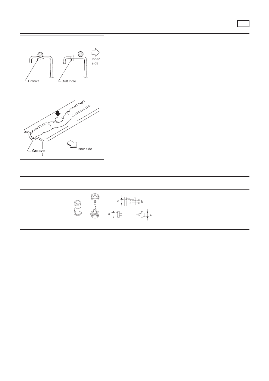
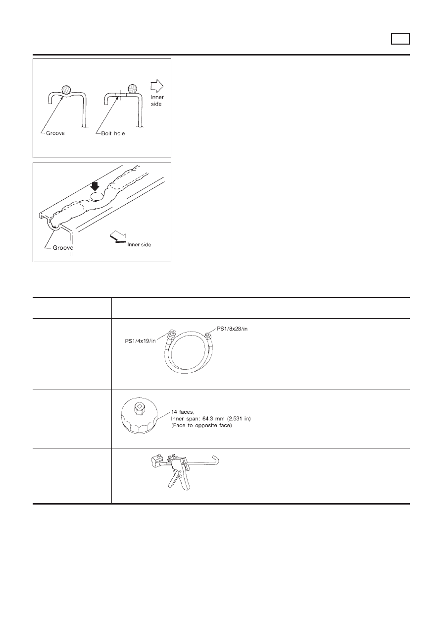
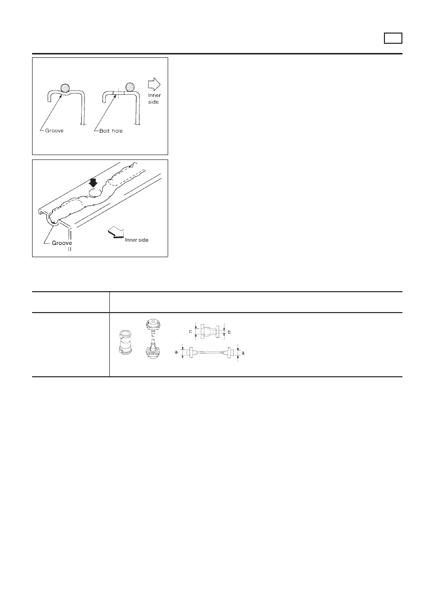
Precautions
LIQUID GASKET APPLICATION PROCEDURE
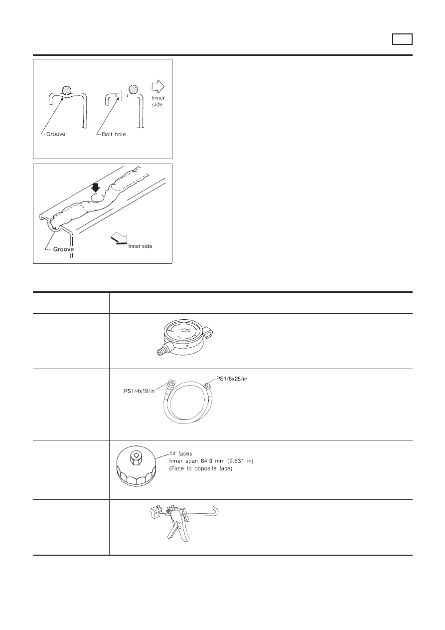
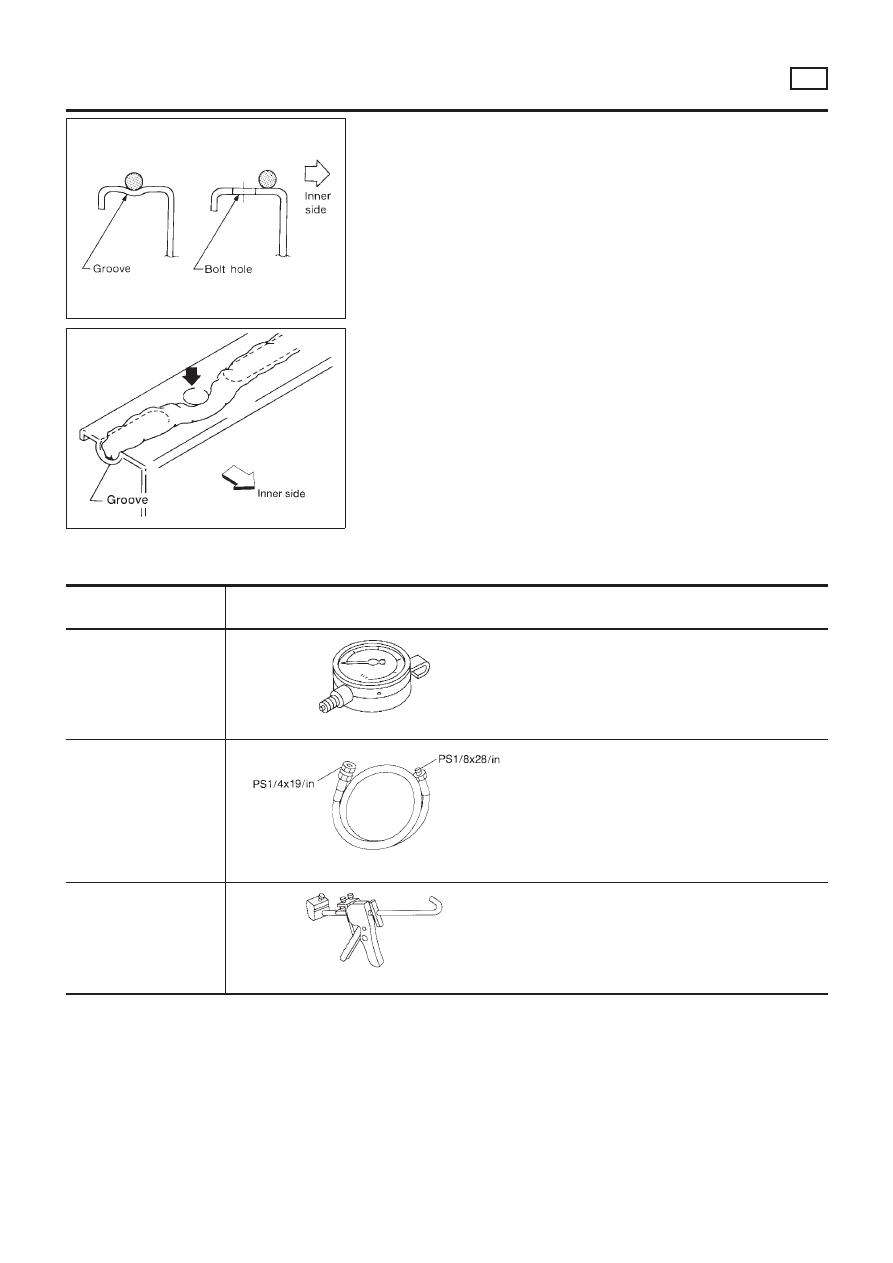
NLLC0001
1.
Use a scraper to remove all traces of old liquid gasket from
mating surfaces and grooves. Also, completely clean any oil
from these areas.
2.
Apply a continuous bead of liquid gasket to mating surfaces.
(Use Genuine Liquid Gasket or equivalent.)
+
For oil pan, be sure liquid gasket diameter is 3.5 to 4.5 mm
(0.138 to 0.177 in).
+
For areas except oil pan, be sure liquid gasket diameter is 2.0
to 3.0 mm (0.079 to 0.118 in).
3.
Apply liquid gasket around the inner side of bolt holes (unless
otherwise specified).
4.
Assembly should be done within 5 minutes after coating.
5.
Wait at least 30 minutes before refilling engine oil and engine
coolant.
Preparation
SPECIAL SERVICE TOOLS
NLLC0002
Tool number
Tool name
Description
ST25051001
Oil pressure gauge
NT050
Measuring oil pressure
ST25052000
Hose
NT559
Adapting oil pressure gauge to cylinder block
KV10115801
Oil filter wrench
NT772
Removing oil filter
WS39930000
Tube presser
NT052
Pressing the tube of liquid gasket
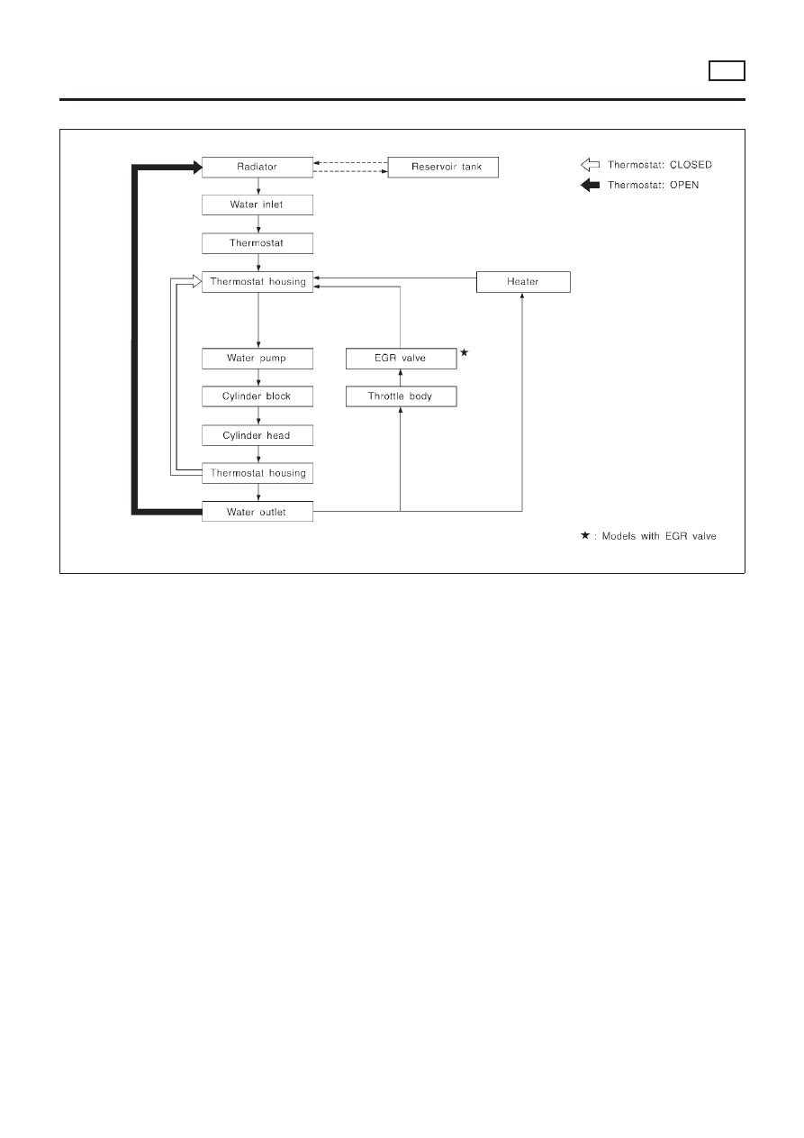
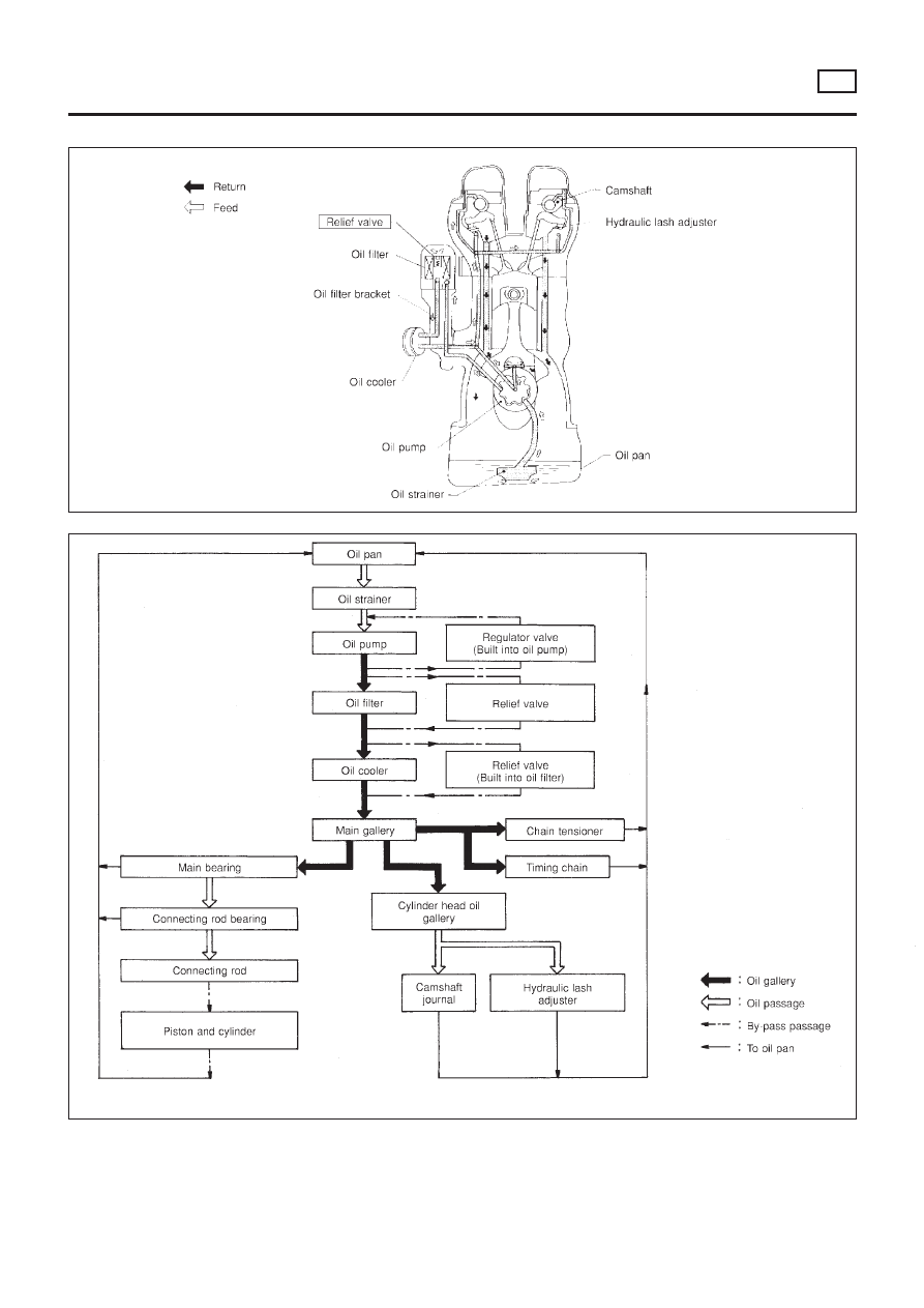
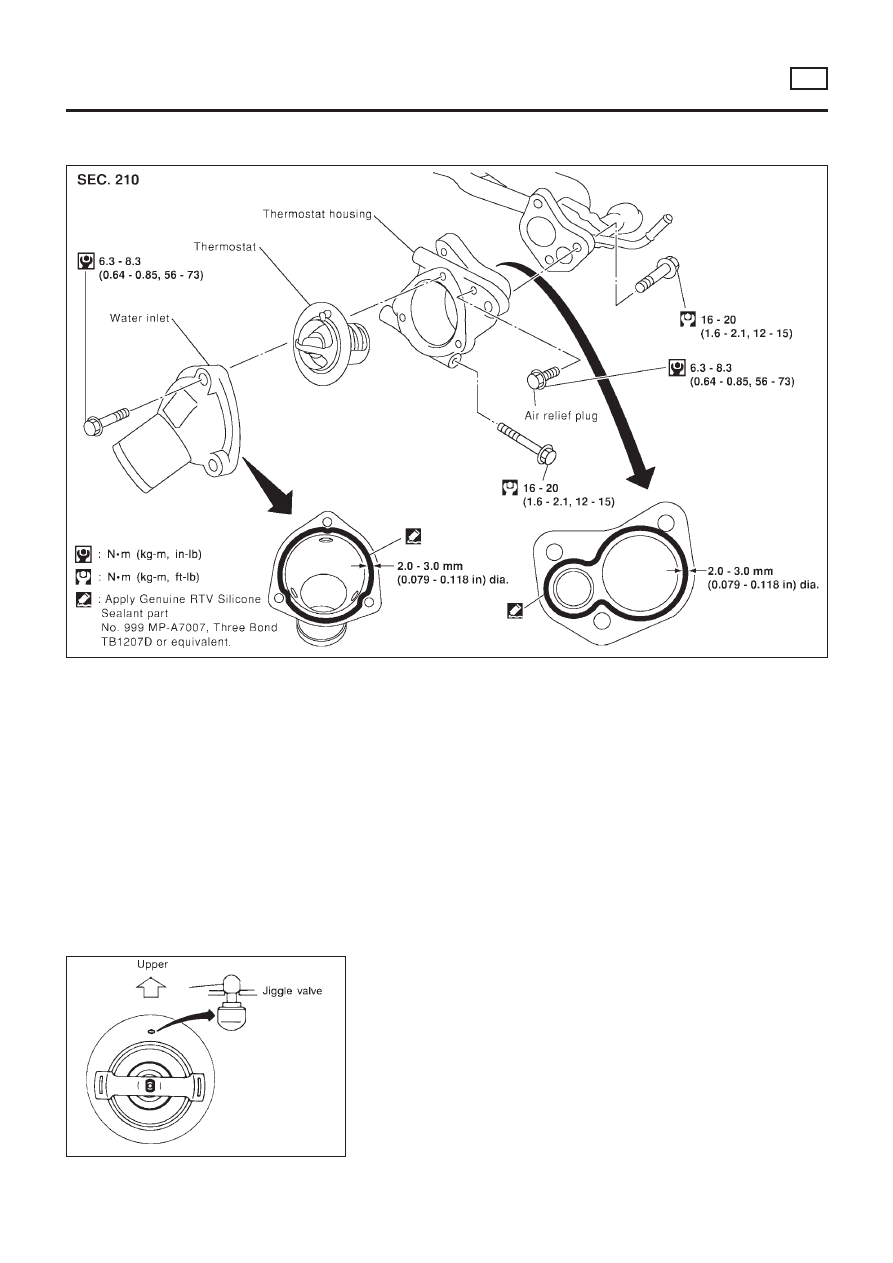
ENGINE LUBRICATION SYSTEM
QG
Precautions
LC-3
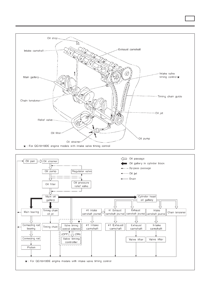
Lubrication Circuit
NLLC0003
SEM852FB
SLC339B
ENGINE LUBRICATION SYSTEM
QG
Lubrication Circuit
LC-4
SEM853F
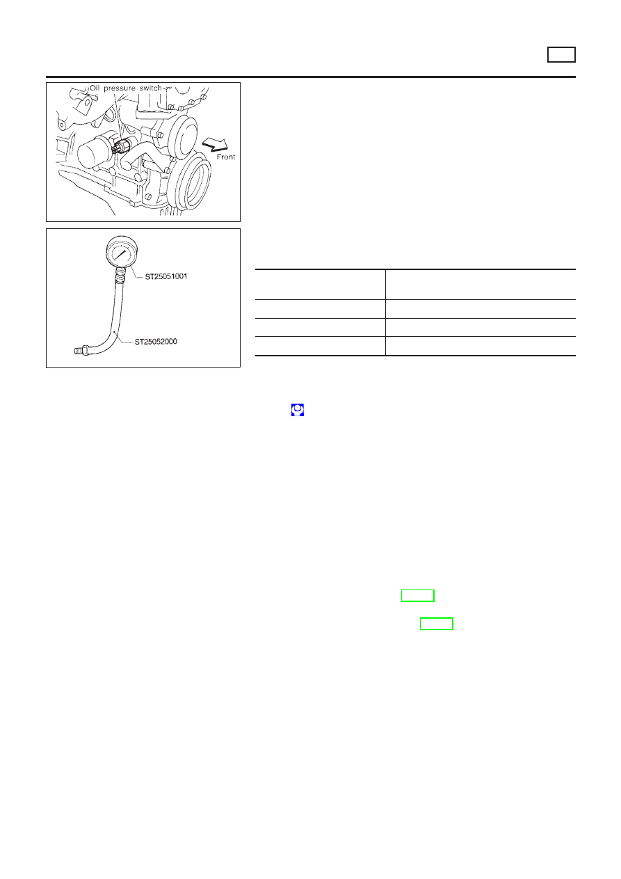
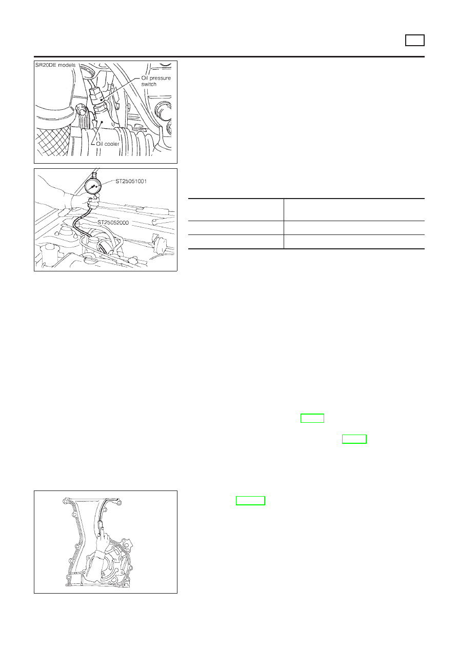
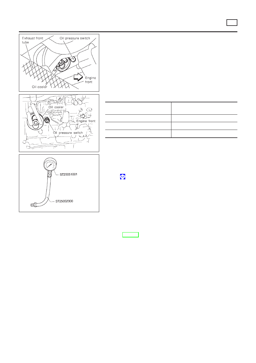
Oil Pressure Check
NLLC0004
WARNING:
+
Be careful not to burn yourself, as the engine and oil may
be hot.
+
For M/T models, put gearshift lever in Neutral “N” posi-
tion.
1.
Check oil level.
2.
Remove oil pressure switch.
SLC926-A
3.
Install pressure gauge.
4.
Start engine and warm it up to normal operating temperature.
5.
Check oil pressure with engine running under no-load.
Engine speed
rpm
Approximate discharge pressure
kPa (bar, kg/cm
2
, psi)
600
More than 98 (0.98, 1.0, 14)
2,000
More than 294 (2.94, 3.0, 43)
6,000
More than 392 (3.92, 4.0, 57)
+
If difference is extreme, check oil passage and oil pump
for oil leaks.
6.
Install oil pressure switch with sealant.
: 13 - 17 N·m (1.25 - 1.75 kg-m, 9 - 12 ft-lb)
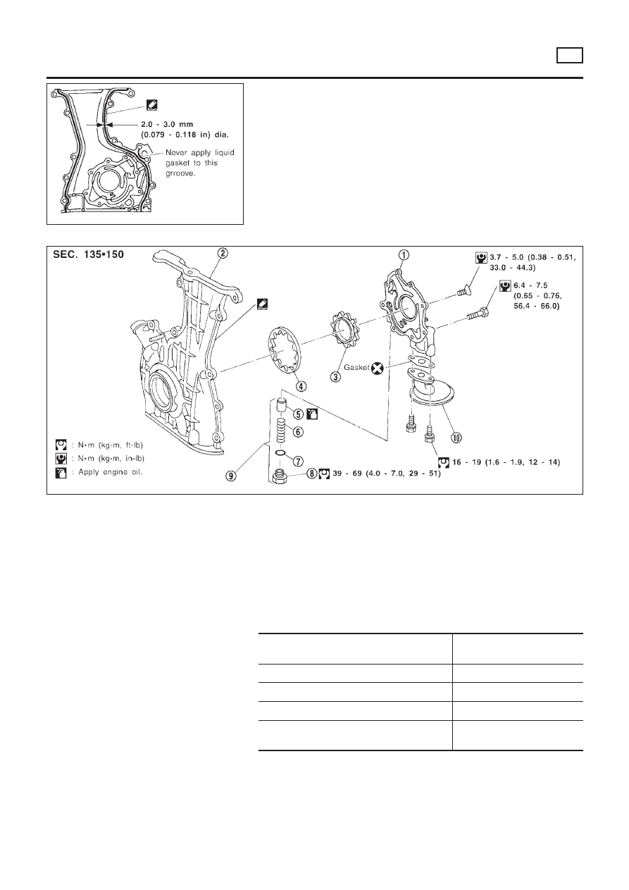
Oil Pump
REMOVAL AND INSTALLATION
NLLC0005
+
Make sure that O-ring is fitted properly.
1.
Drain engine oil.
2.
Remove drive belts.
3.
Remove oil pan. Refer to EM-20, “OIL PAN”.
4.
Remove oil strainer.
5.
Remove front cover. Refer to EM-22, “TIMING CHAIN”.
6.
Install front cover.
7.
Reinstall parts in reverse order of removal.
ENGINE LUBRICATION SYSTEM
QG
Oil Pressure Check
LC-5
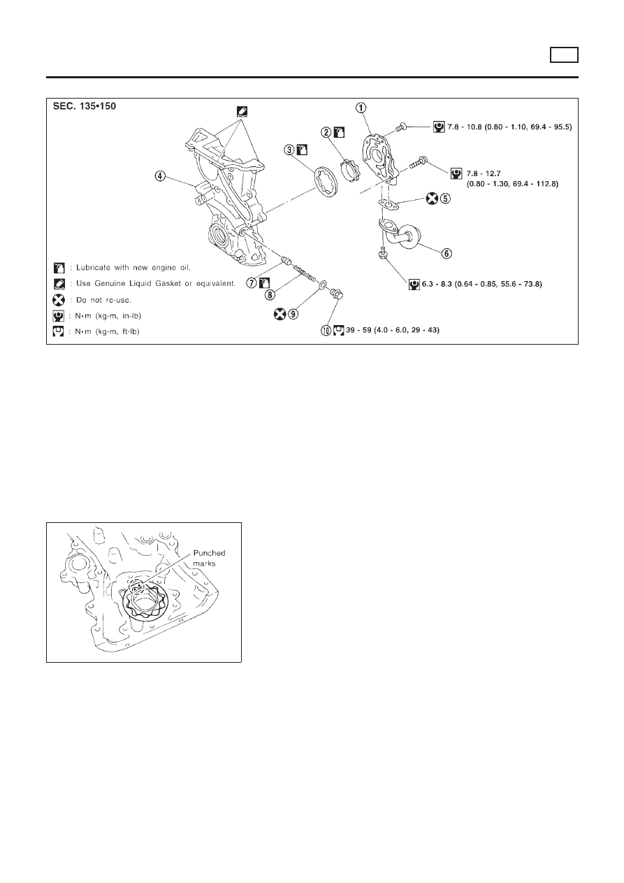
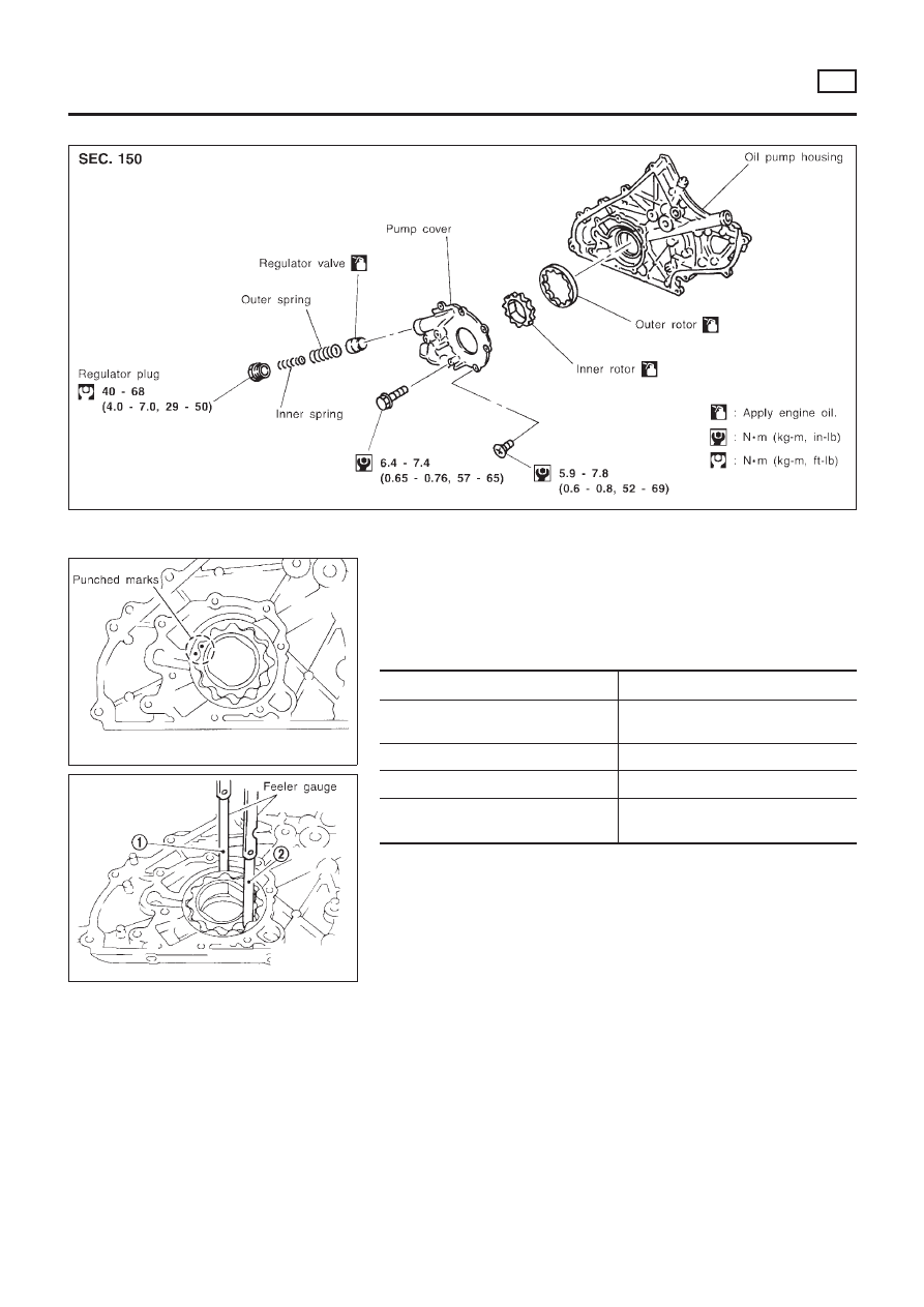
DISASSEMBLY AND ASSEMBLY
NLLC0006
SEM854FA
1.
Oil pump cover
2.
Inner rotor
3.
Outer rotor
4.
Front cover
5.
Gasket
6.
Oil strainer
7.
Regulator valve
8.
Spring
9.
Washer
10. Plug
+
When installing oil pump, apply engine oil to rotors.
JLC307B
+
Install the inner rotor and outer rotor with the punched
marks on the oil pump cover side.
ENGINE LUBRICATION SYSTEM
QG
Oil Pump (Cont’d)
LC-6
SEM855F
SEM856F
INSPECTION
NLLC0007
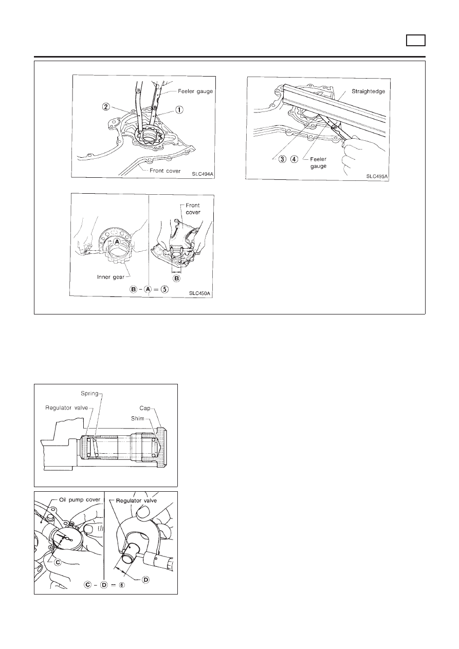
Using a feeler gauge, check the following clearances.
Standard clearance:
Unit: mm (in)
Body to outer rotor radial clearance 1
0.250 - 0.325 (0.0098 - 0.0128)
Inner rotor to outer rotor tip clearance
2
Below 0.18 (0.0071)
Body to inner rotor clearance 3
0.030 - 0.085 (0.0012 - 0.0033)
Body to outer rotor axial clearance 4
0.030 - 0.090 (0.0012 - 0.0035)
Inner rotor to brazed portion of hous-
ing clearance 5
0.045 - 0.091 (0.0018 - 0.0036)
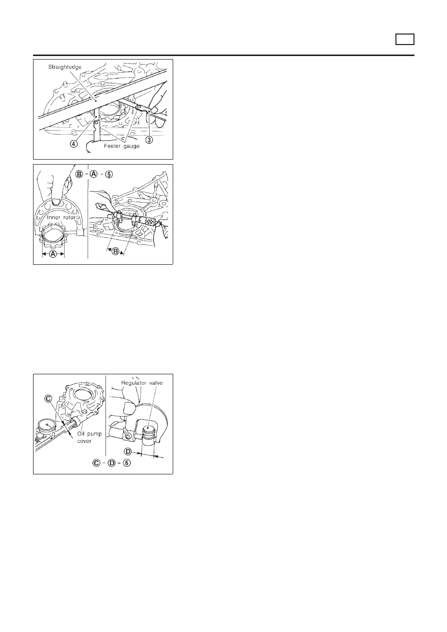
SEM857FA
+
If the tip clearance (2) exceeds the limit, replace rotor set.
+
If body to rotor clearances (1, 3, 4, 5) exceed the limit,
replace front cover assembly.
SLC986AA
REGULATOR VALVE INSPECTION
NLLC0008
1.
Visually inspect components for wear and damage.
2.
Check oil pressure regulator valve sliding surface and valve
spring.
3.
Coat regulator valve with engine oil.
Check that it falls smoothly into the valve hole by its own
weight.
If damaged, replace regulator valve set or front cover assem-
bly.
ENGINE LUBRICATION SYSTEM
QG
Oil Pump (Cont’d)
LC-7
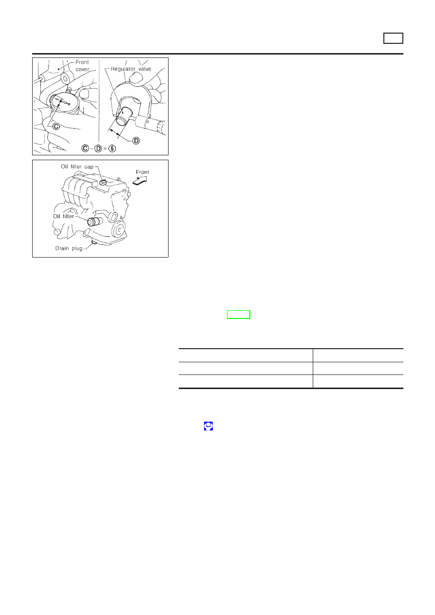
SLC101B
4.
Check regulator valve to front cover clearance.
Clearance 6:
0.052 - 0.088 mm (0.0020 - 0.0035 in)
If it exceeds the limit, replace front cover assembly.
SMA915C
Changing Engine Oil
NLLC0035
WARNING:
+
Be careful not to burn yourself, as the engine oil is hot.
+
Prolonged and repeated contact with used engine oil may
cause skin cancer; try to avoid direct skin contact with
used oil. If skin contact is made, wash thoroughly with
soap or hand cleaner as soon as possible.
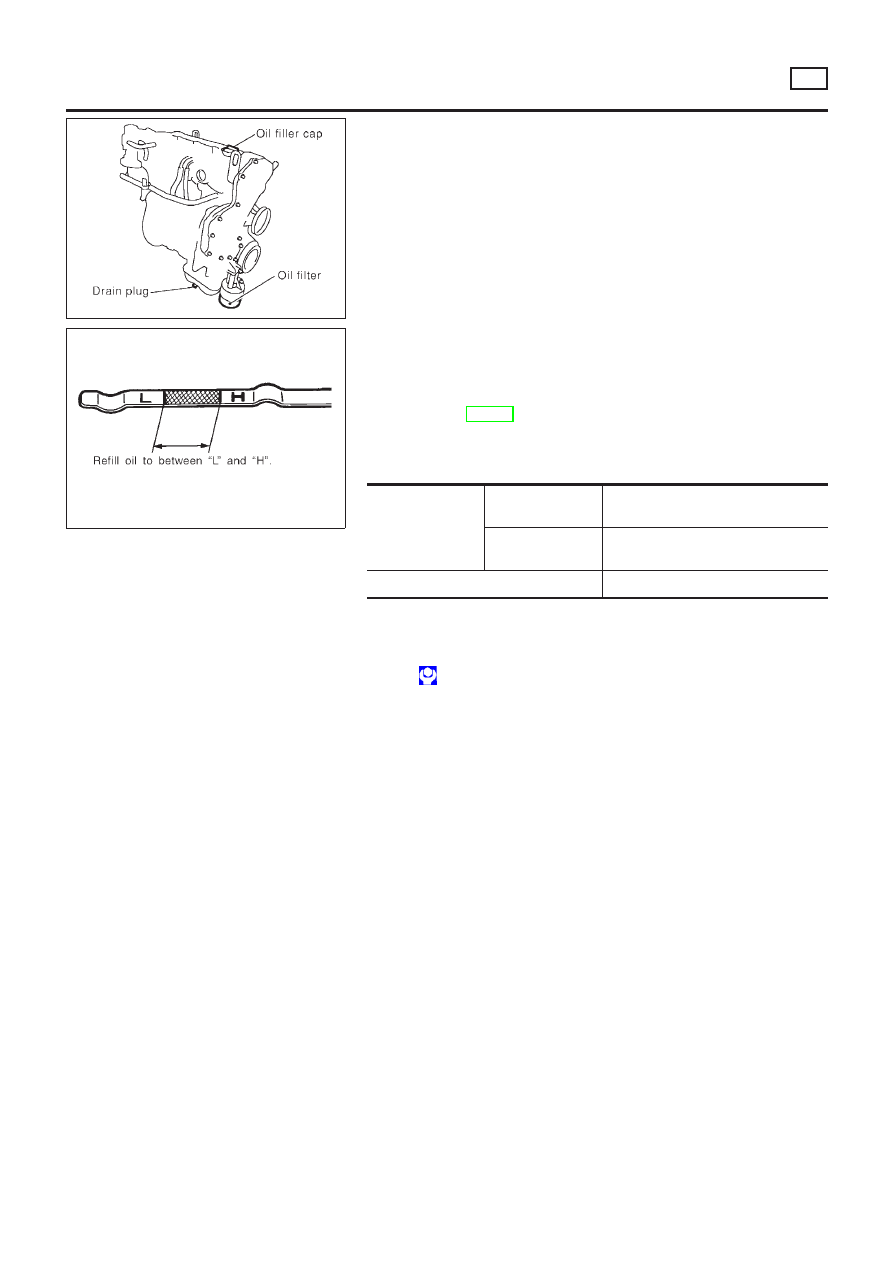
1.
Warm up engine, and check for oil leakage from engine com-
ponents.
2.
Stop engine and wait more than 10 minutes.
3.
Remove drain plug and oil filler cap.
4.
Drain oil and refill with new engine oil.
Oil specification and viscosity (For Europe):
+
API grade SG, SH or SJ
+
ACEA grade A1-98, A3-98
+
ILSAC grade GF-I, GF-II
Refer to MA-20, “RECOMMENDED FLUIDS AND LUBRI-
CANTS”.
Refill oil capacity (Approximate):
Unit:
!
(Imp qt)
With oil filter change
2.7 (2-3/8)
Without oil filter change
2.5 (2-1/4)
Dry engine (engine overhaul)
3.1 (2-3/4)
CAUTION:
+
Be sure to clean drain plug and install with new washer.
Drain plug:
: 29 - 39 N·m (3.0 - 4.0 kg-m, 22 - 29 ft-lb)
+
The refill capacity changes depending on the oil tempera-
ture and drain time, use these values as a reference and
be certain to check with the dipstick when changing the
oil.
ENGINE LUBRICATION SYSTEM
QG
Oil Pump (Cont’d)
LC-8
SMA390C
5.
Check oil level.
6.
Start engine and check area around drain plug and oil filter for
oil leakage.
7.
Run engine for a few minutes, then turn it off. After several
minutes, check oil level.
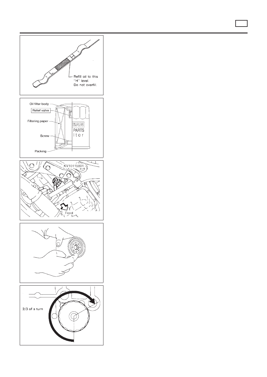
ALC094
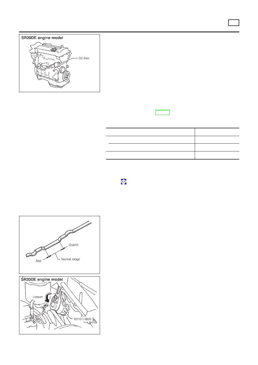
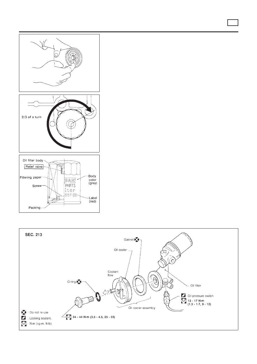
Changing Oil Filter
NLLC0010
The oil filter is a small, full-flow cartridge type and is provided with
a relief valve.
+
Use Tool KV10115801 for removing oil filter.
SLC275B
1.
Remove oil filter with Tool.
WARNING:
Be careful not to burn yourself, as the engine and the engine
oil are hot.
SMA010
2.
Clean oil filter mounting surface on cylinder block. Coat rubber
seal of new oil filter with engine oil.
SMA229B
3.
Screw in the oil filter until a slight resistance is felt, then tighten
an additional 2/3 turn.
4.
Add engine oil.
Refer to Changing Engine Oil.
+
Clean excess oil from engine.
ENGINE LUBRICATION SYSTEM
QG
Changing Engine Oil (Cont’d)
LC-9
Service Data and Specifications (SDS)
OIL PRESSURE CHECK
NLLC0011
Engine speed
rpm
Approximate discharge pressure
kPa (bar, kg/cm
2
, psi)
600
More than 98 (0.98, 1.0, 14)
2,000
More than 294 (2.94, 3.0, 43)
6,000
More than 392 (3.92, 4.0, 57)
OIL PUMP INSPECTION
NLLC0013
Unit: mm (in)
Body to outer rotor radial clearance
0.250 - 0.325 (0.0098 - 0.0128)
Inner rotor to outer rotor tip clearance
Below 0.18 (0.0071)
Body to inner rotor clearance
0.030 - 0.085 (0.0012 - 0.0033)
Body to outer rotor axial clearance
0.030 - 0.090 (0.0012 - 0.0035)
Inner rotor to brazed portion of housing clearance
0.045 - 0.091 (0.0018 - 0.0036)
REGULATOR VALVE INSPECTION
NLLC0012
Unit: mm (in)
Regulator valve to oil pump cover clearance
0.052 - 0.088 (0.0020 - 0.0035)
OIL CAPACITY
NLLC0036
Unit:
!
(Imp qt)
With oil filter change
2.7 (2-3/8)
Without oil filter change
2.5 (2-1/4)
Dry engine (engine overhaul)
3.1 (2-3/4)
ENGINE LUBRICATION SYSTEM
QG
Service Data and Specifications (SDS)
LC-10
SEM164F
AEM080
Precautions
LIQUID GASKET APPLICATION PROCEDURE
NLLC0014
1.
Use a scraper to remove all traces of old liquid gasket from
mating surfaces and grooves. Also, completely clean any oil
from these areas.
2.
Apply a continuous bead of liquid gasket to mating surfaces.
(Use Genuine Liquid Gasket or equivalent).
+
For oil pan, be sure liquid gasket diameter is 3.5 to 4.5 mm
(0.138 to 0.177 in).
+
For areas except oil pan, be sure liquid gasket diameter is 2.0
to 3.0 mm (0.079 to 0.118 in).
3.
Apply liquid gasket around the inner side of bolt holes (unless
otherwise specified).
4.
Assembly should be done within 5 minutes after coating.
5.
Wait at least 30 minutes before refilling engine oil and engine
coolant.
Preparation
SPECIAL SERVICE TOOLS
NLLC0015
Tool number
Tool name
Description
EG17650301
Radiator cap tester
adapter
NT564
Adapting radiator cap tester to radiator filler neck
a: 28 (1.10) dia.
b: 31.4 (1.236) dia.
c: 41.3 (1.626) dia.
Unit: mm (in)
ENGINE COOLING SYSTEM
QG
Precautions
LC-11
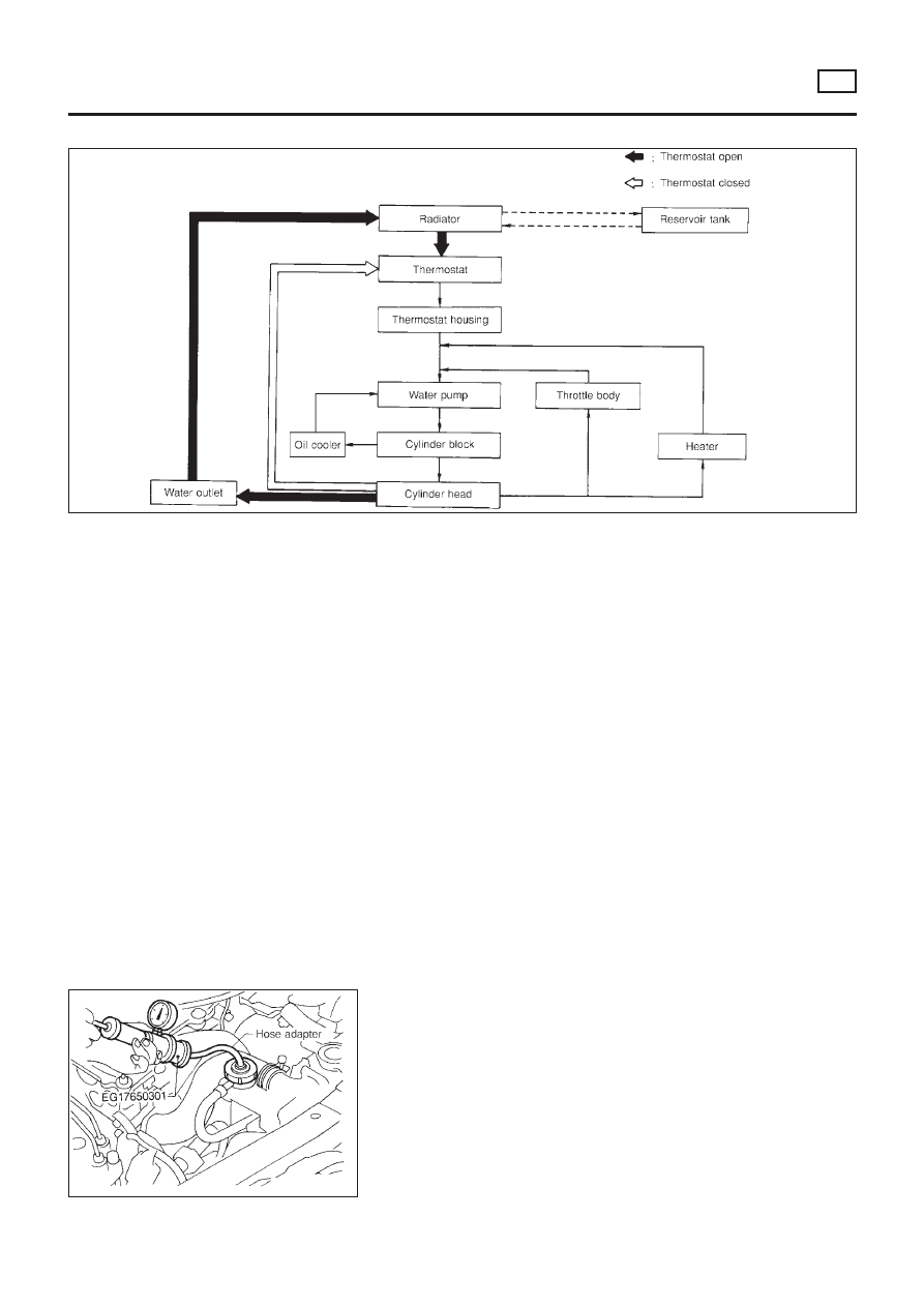
Cooling Circuit
NLLC0016
SLC317B
System Check
NLLC0017
WARNING:
Never remove the radiator cap when the engine is hot. Serious
burns could occur from high pressure fluid escaping from the
radiator.
Wrap a thick cloth around the cap. Slowly turn it a quarter turn
to allow built-up pressure to escape. Carefully remove the cap
by turning it all the way.
CHECKING COOLING SYSTEM HOSES
NLLC0017S01
Check hoses for the following:
+
Improper attachment
+
Leaks
+
Cracks
+
Damage
+
Loose connections
+
Chafing
+
Deterioration
ENGINE COOLING SYSTEM
QG
Cooling Circuit
LC-12
CHECKING RADIATOR
NLLC0017S04
Check radiator for mud or clogging. If necessary, clean radiator as
follows.
+
Be careful not to bend or damage the radiator fins.
+
When radiator is cleaned without removal, remove all sur-
rounding parts such as cooling fan, radiator shroud and horns.
Then tape the harness and connectors to prevent water from
entering.
1.
Apply water by hose to the back side of the radiator core ver-
tically download.
2.
Apply water again to all radiator core surfaces once per
minute.
3.
Stop washing if any stains no longer flow out from the radia-
tor.
4.
Blow air into the back side of radiator core vertically download.
+
Use compressed air lower than 490 kPa (4.9 bar, 5 kg/cm
2
, 71
psi) and keep distance more than 30 cm (11.8 in).
5.
Blow air again into all the radiator core surfaces once per
minute until no water sprays out.
SLC613-A
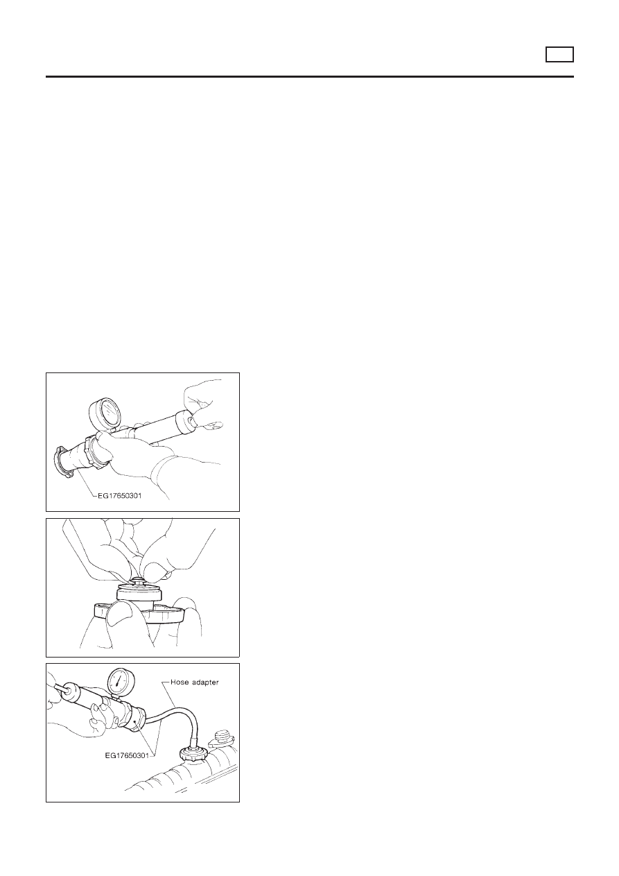
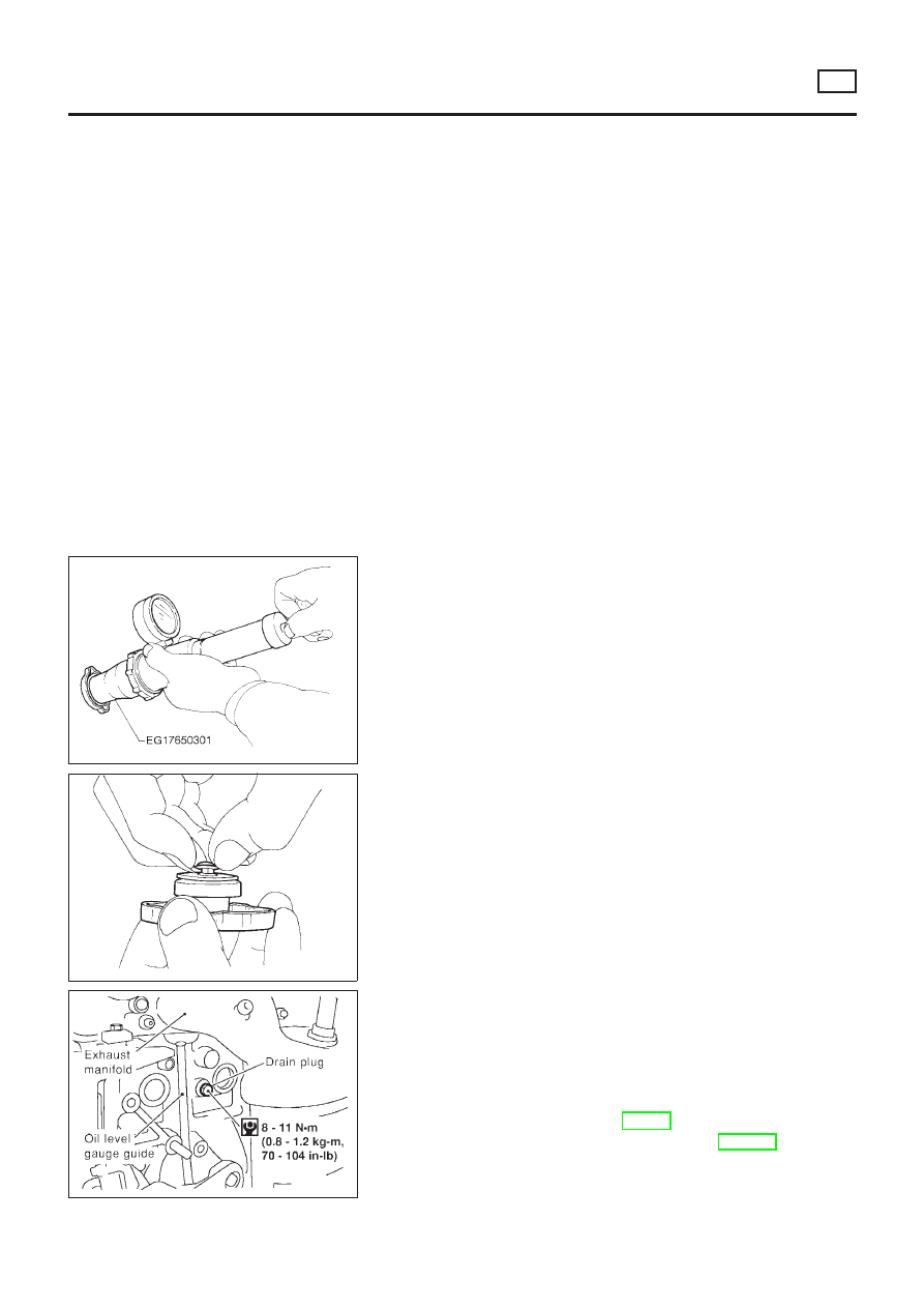
CHECKING RADIATOR CAP
NLLC0017S03
To check radiator cap, apply pressure to cap with a tester.
Radiator cap relief pressure:
Standard
78 - 98 kPa
(0.78 - 0.98 bar, 0.8 - 1.0 kg/cm
2
, 11 - 14 psi)
Limit
59 - 98 kPa
(0.59 - 0.98 bar, 0.6 - 1.0 kg/cm
2
, 9 - 14 psi)
SMA967B
Pull the negative pressure valve to open it.
Check that it closes completely when released.
SLC756AA
CHECKING COOLING SYSTEM FOR LEAKS
NLLC0017S02
To check for leakage, apply pressure to the cooling system with a
tester.
Testing pressure:
157 kPa (1.57 bar, 1.6 kg/cm
2
, 23 psi)
CAUTION:
Higher pressure than specified may cause radiator damage.
ENGINE COOLING SYSTEM
QG
System Check (Cont’d)
LC-13
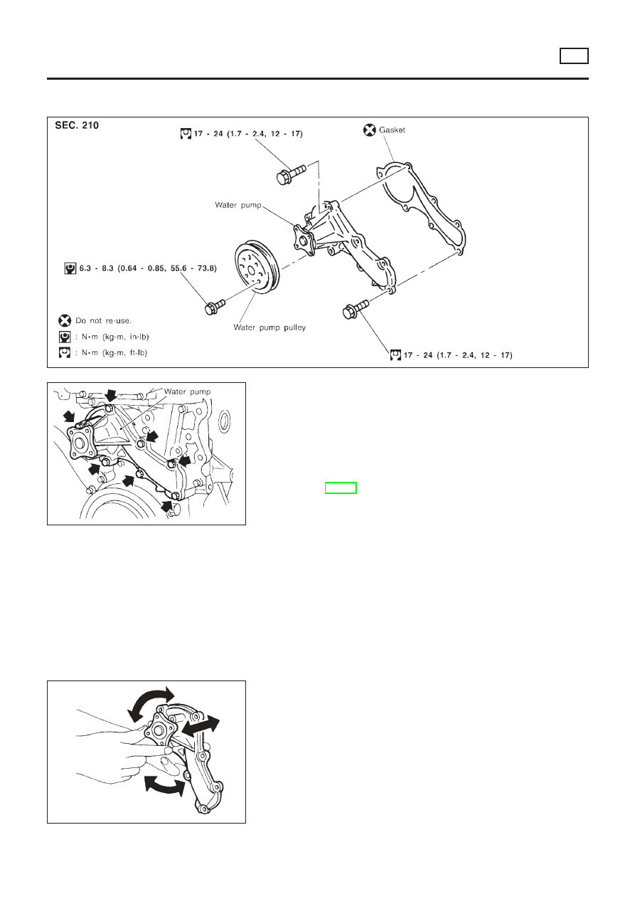
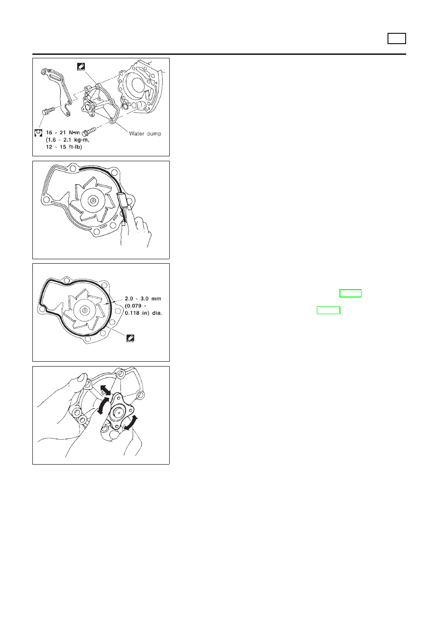
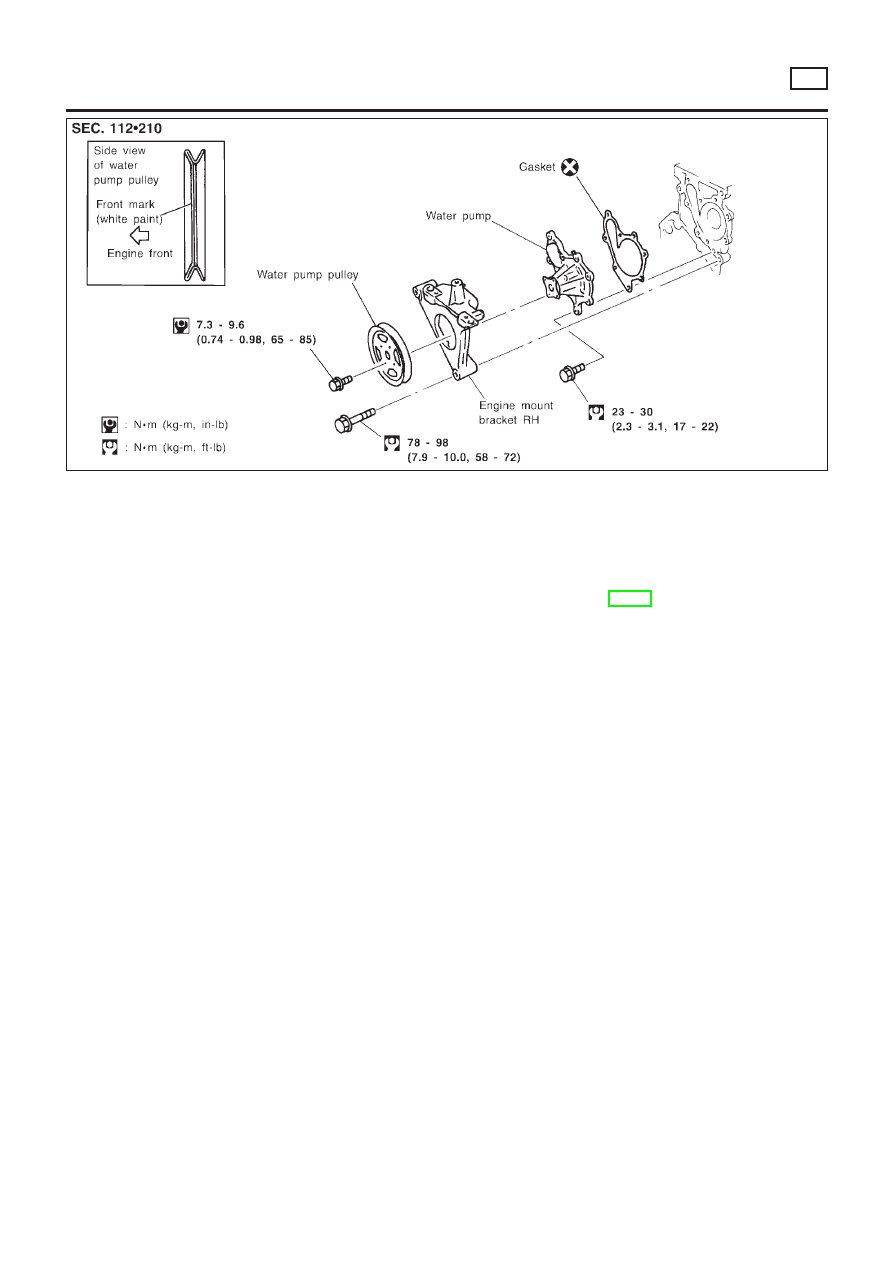
Water Pump
REMOVAL AND INSTALLATION
NLLC0018
SEM858F
SEM859F
CAUTION:
+
When removing water pump assembly, be careful not to
get coolant on drive belt.
+
Water pump cannot be disassembled and should be
replaced as a unit.
+
After installing water pump, and check for leaks using
radiator cap tester.
1.
Drain engine coolant.
Refer to LC-19, “Changing Engine Coolant”.
2.
Remove drive belts and idler pulley.
3.
Loosen water pump pulley bolts.
4.
Remove water pump pulley.
5.
Remove front right wheel.
6.
Remove front right undercover and front right fender protector.
7.
Remove water pump bolts.
8.
Remove water pump.
9.
Reinstall parts in reverse order of removal.
SEM860F
INSPECTION
NLLC0019
+
Check body assembly and vane for rust or corrosion.
+
Check for rough operation due to excessive end play.
ENGINE COOLING SYSTEM
QG
Water Pump
LC-14
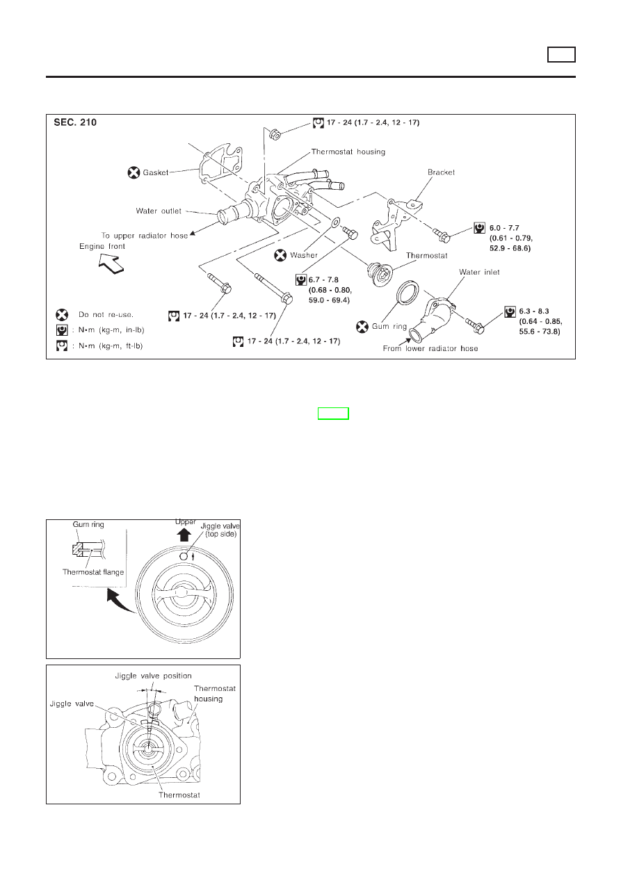
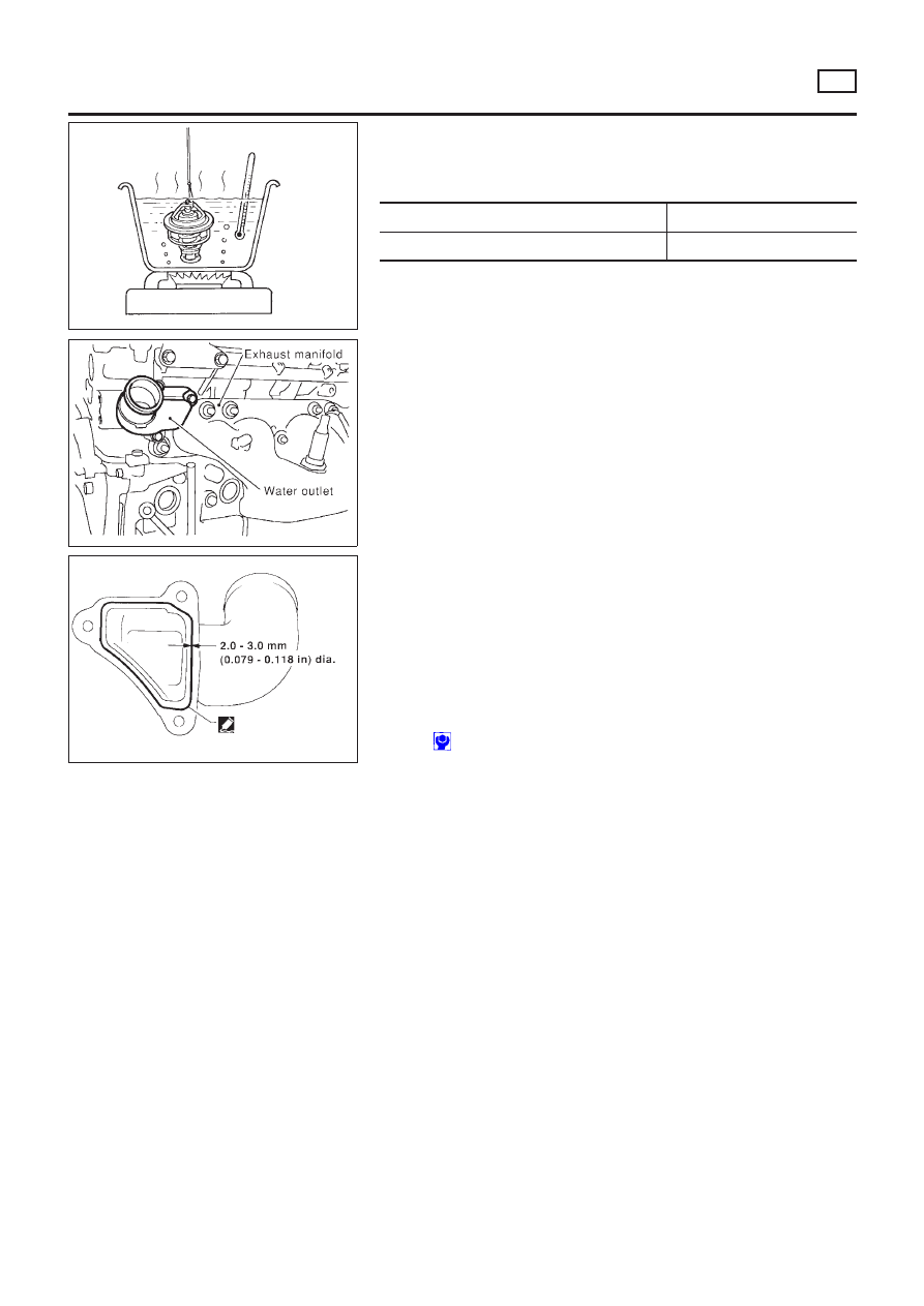
Thermostat
REMOVAL AND INSTALLATION
NLLC0021
SEM861F
Be careful not to spill coolant over engine compartment. Use
a rag to absorb coolant.
1.
Drain engine coolant.
Refer to LC-19, “Changing Engine Coolant”.
2.
Remove water inlet, then take out thermostat.
SEM862F
3.
Install gum ring to thermostat.
SEM863F
4.
Install thermostat with jiggle valve or air bleeder at upper side.
After installation, run engine for a few minutes, and check
for leaks.
ENGINE COOLING SYSTEM
QG
Thermostat
LC-15
SLC343
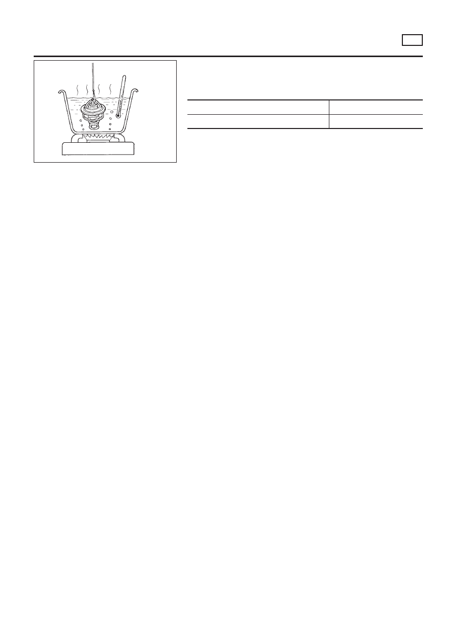
INSPECTION
NLLC0022
1.
Check for valve seating condition at normal room temperature.
It should seat tightly.
2.
Check valve opening temperature and valve lift.
Valve opening temperature
°C (°F)
82 (180)
Valve lift
mm/°C (in/°F)
More than 8/95 (0.31/203)
3.
Then check if valve closes at 5°C (9°F) below valve opening
temperature.
ENGINE COOLING SYSTEM
QG
Thermostat (Cont’d)
LC-16
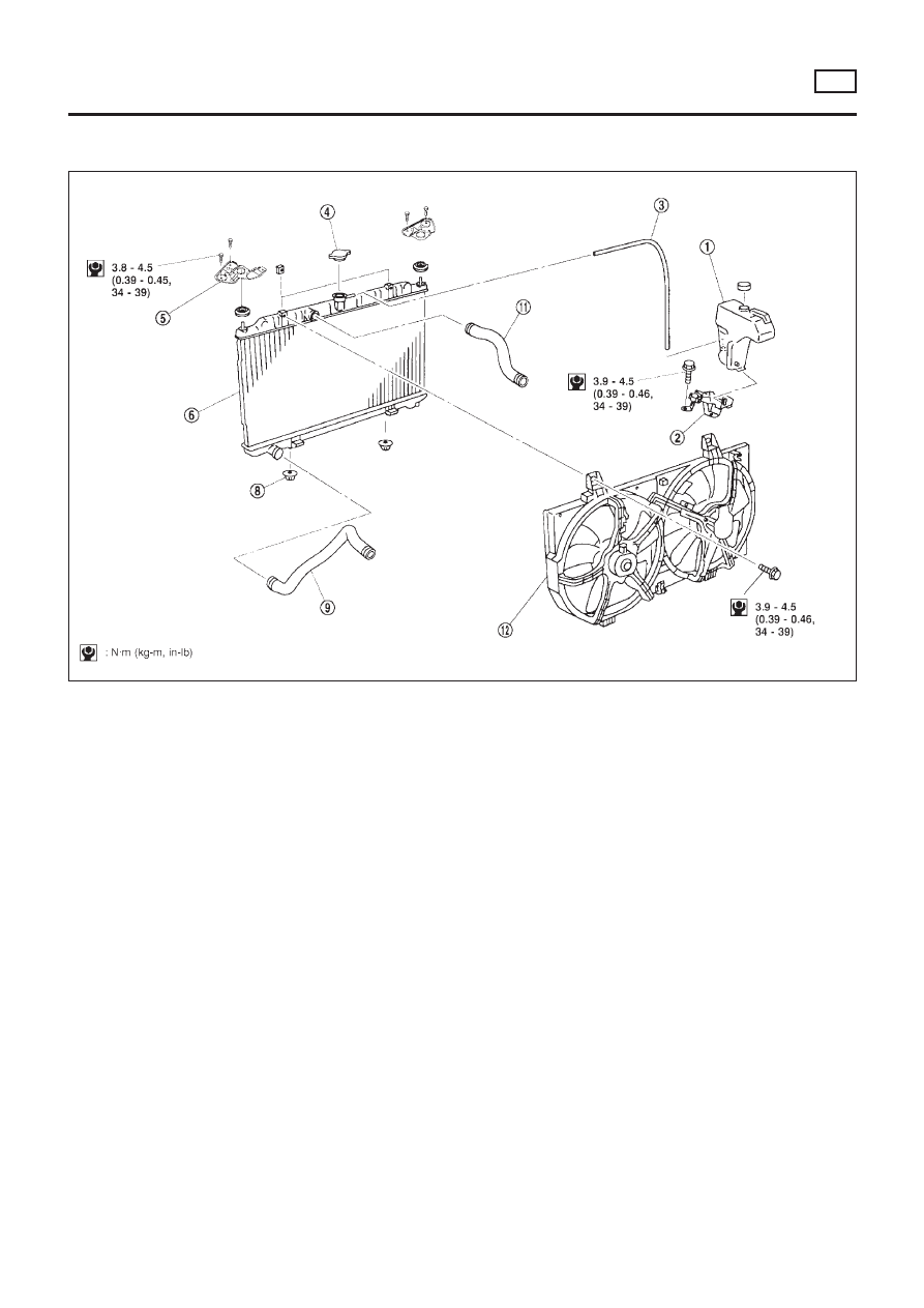
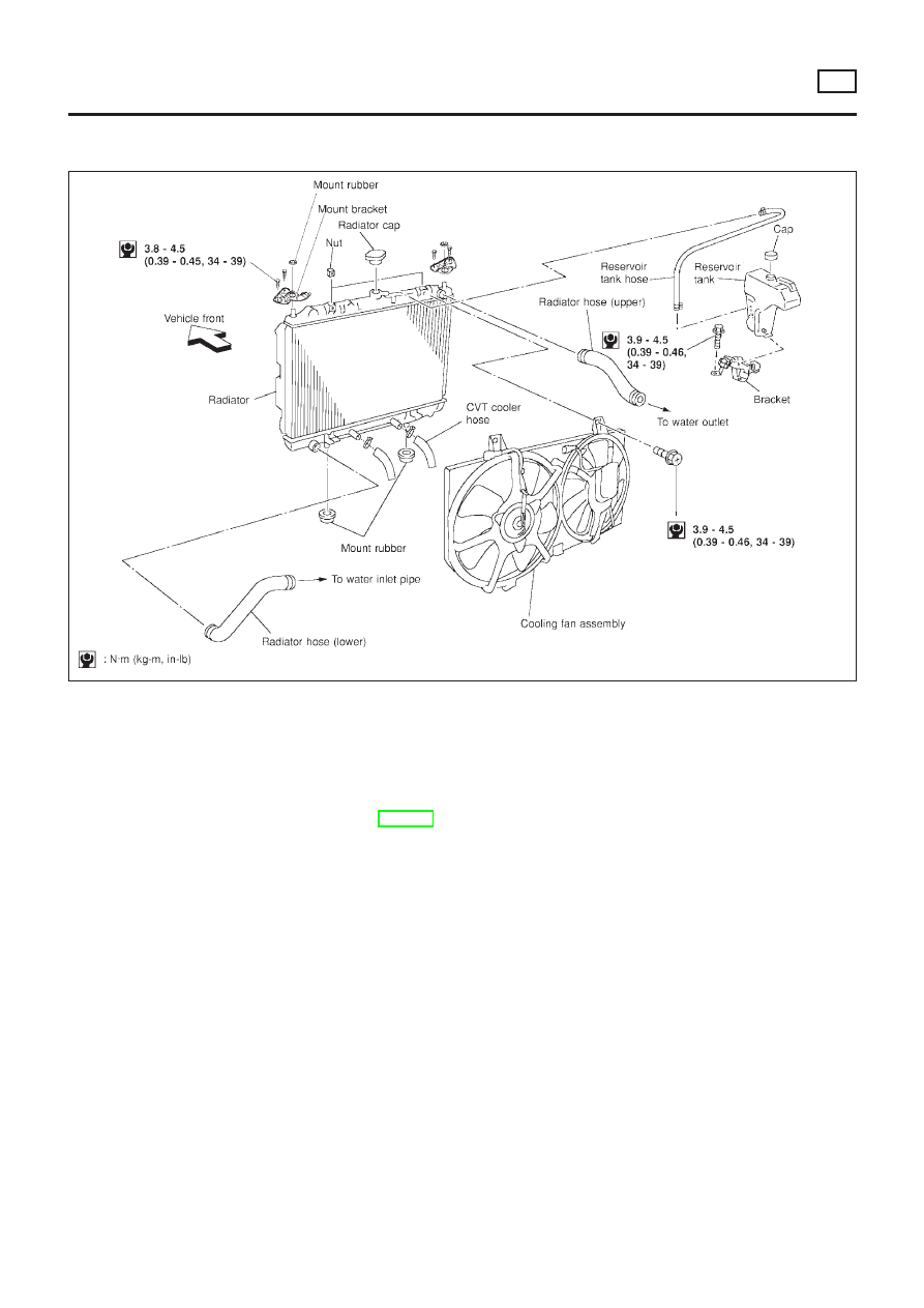
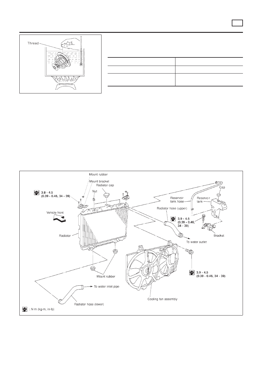
Radiator
COMPONENTS
=NLLC0025
NLC091
1.
Reservoir tank
2.
Reservoir tank bracket
3.
Reservoir hose
4.
Radiator cap
5.
Mounting bracket
6.
Radiator
7.
Mounting rubber
8.
Lower radiator hose
9.
Upper radiator hose
10. Cooling fan assembly
ENGINE COOLING SYSTEM
QG
Radiator
LC-17
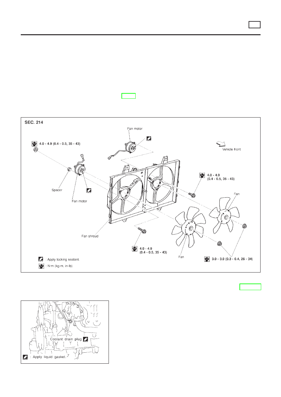
Cooling Fan
NLLC0026
COMPONENTS
NLLC0026S01
YLC011
ENGINE COOLING SYSTEM
QG
Cooling Fan
LC-18
CONTROL SYSTEM
NLLC0026S02
Cooling fans are controlled by the ECM. For details, refer to
EC-373, TROUBLE DIAGNOSIS FOR OVERHEAT (COOLING
SYSTEM).
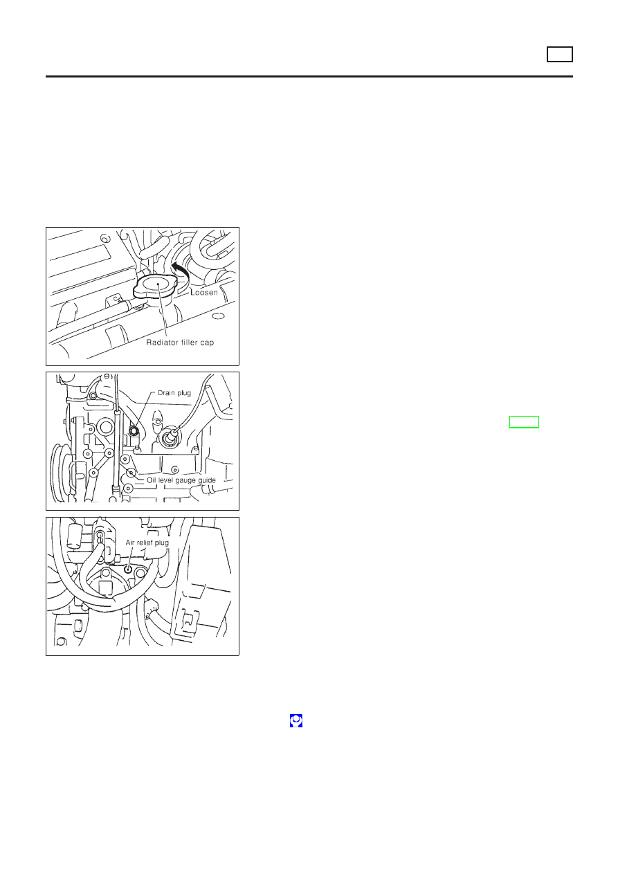
Changing Engine Coolant
NLLC0037
WARNING:
To avoid the danger of being scalded, never change the cool-
ant when the engine is hot.
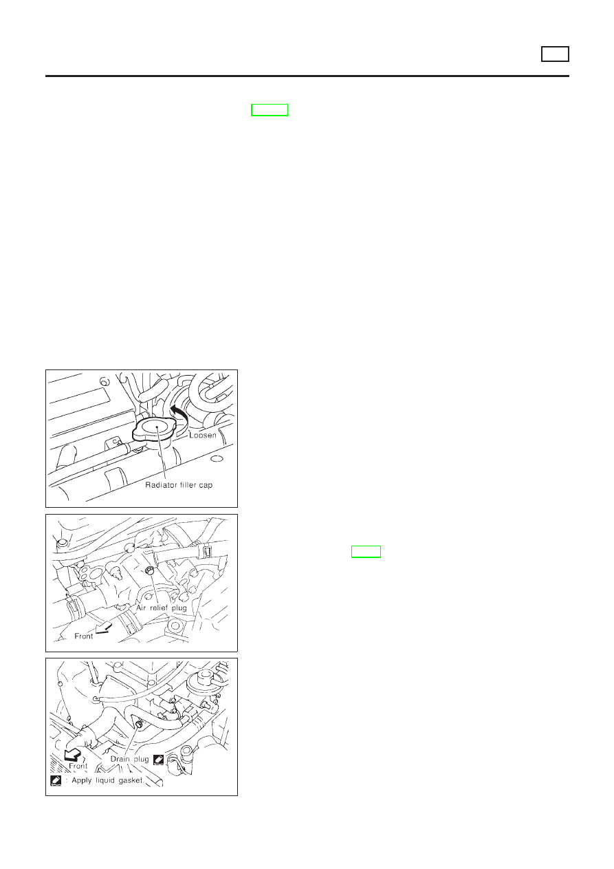
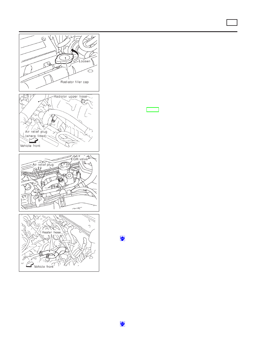
— DRAINING ENGINE COOLANT —
NLLC0037S01
1. Set air conditioning system as follows to prevent coolant from
remaining in the system.
a. Turn ignition switch ON and set temperature controller to maxi-
mum hot position.
b. Wait 10 seconds before turning ignition switch OFF.
SMA033D
2. Remove lower radiator hose, and remove radiator filler cap to
drain coolant.
3. Remove reservoir tank, drain coolant, then clean reservoir
tank.
+
Be careful not to allow coolant to contact drive belts.
4. Cover the exhaust tube heat shield to prevent from splashing
coolant.
SLC277B
SLC278B
5. Remove drain plug on cylinder block and air relief plug.
6. Check drained coolant for contaminants such as rust, corro-
sion or discoloration. If contaminated flush engine cooling
system, refer to LC-20, “FLUSHING COOLING SYSTEM”.
7. Blow the coolant around the exhaust tube heat shield.
ENGINE COOLING SYSTEM
QG
Cooling Fan (Cont’d)
LC-19
— REFILLING ENGINE COOLANT —
NLLC0037S02
1.
Install reservoir tank, lower radiator hose and cylinder block
drain plug.
+
Apply sealant to the thread of cylinder block drain plug.
: 35 - 44 N·m (3.50 - 4.50 kg-m, 26 - 32 ft-lb)
2.
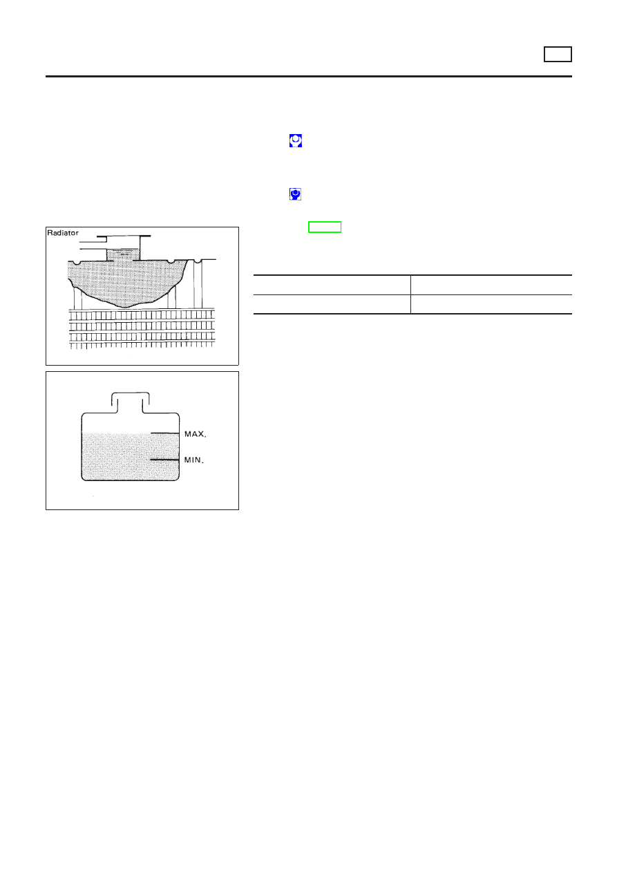
Fill radiator slowly with coolant until coolant spills from the air
relief plug, then install air relief plug.
Air relief plug:
: 6.7 - 7.8 N·m (0.68 - 0.80 kg-m, 59 - 69 in-lb)
+
Use genuine Nissan anti-freeze coolant or equivalent.
SMA182B
SMA412B
Refer to MA-20, “RECOMMENDED FLUIDS AND LUBRI-
CANTS”.
Coolant capacity:
Unit:
!
(Imp qt)
With reservoir tank
6.75 (6)
Reservoir tank
0.7 (5/8)
+
Pour coolant through coolant filler neck slowly to allow air
in system to escape.
3.
Fill radiator and reservoir tank to specified level.
4.
Warm up engine to normal operating temperature without
radiator cap installed.
+
If coolant overflows radiator filler hole, install filler cap.
5.
Run engine at 2,500 rpm for 10 seconds and return to idle
speed with radiator cap installed.
+
Repeat two or three times.
Watch coolant temperature gauge so as not to overheat the
engine.
6.
Stop engine and cool it down.
+
Cool down using a fan to reduce the time.
+
If necessary, refill radiator up to filler neck with coolant.
7.
Refill reservoir tank to MAX level line with coolant.
8.
Repeat steps 4 through 7 two or more times with radiator cap
installed until coolant level no longer drops.
9.
Check cooling system for leaks with engine running.
10. Warm up engine, and check for sound of coolant flow while
running engine from idle up to 3,000 rpm with heater tempera-
ture controller set at several positions between COOL and
HOT.
+
Sound may be noticeable at heater water cock.
11. If sound is heard, bleed air from cooling system by repeating
steps 4 through 7 until coolant level no longer drops
+
Clean excess coolant from engine.
— FLUSHING COOLING SYSTEM —
NLLC0037S03
1.
Open air relief plug.
2.
Fill radiator with water until water spills from the air relief hole,
then close air relief plug. Fill radiator and reservoir tank with
water and reinstall radiator cap.
3.
Run engine and warm it up to normal operating temperature.
4.
Rev engine two or three times under no-load.
5.
Stop engine and wait until it cools down.
6.
Drain water.
ENGINE COOLING SYSTEM
QG
Changing Engine Coolant (Cont’d)
LC-20
7.
Repeat steps 1 through 6 until clear water begins to drain from
radiator.
Overheating Cause Analysis
NLLC0028
Symptom
Check items
Cooling sys-
tem parts
malfunction
Poor heat transfer
Water pump malfunction
Worn or loose drive belt
—
Thermostat stuck closed
—
Damaged fins
Dust contamination or
paper clogging
Mechanical damage
Clogged radiator cooling
tube
Excess foreign material
(rust, dirt, sand, etc.)
Reduced air flow
Cooling fan does not oper-
ate
—
—
High resistance to fan rota-
tion
Damaged fan blades
Damaged radiator shroud
—
—
—
Improper coolant mixture
ratio
—
—
—
Poor coolant quality
—
—
—
Insufficient coolant
Coolant leaks
Cooling hose
Loose clamp
Cracked hose
Water pump
Poor sealing
Radiator cap
Loose
Poor sealing
Radiator
O-ring for damage, deterio-
ration or improper fitting
Cracked radiator tank
Cracked radiator core
Reservoir tank
Cracked reservoir tank
Overflowing reservoir tank
Exhaust gas leaks into
cooling system
Cylinder head deterioration
Cylinder head gasket dete-
rioration
ENGINE COOLING SYSTEM
QG
Overheating Cause Analysis
LC-21

Symptom
Check items
Except cool-
ing system
parts mal-
function
—
Overload on engine
Abusive driving
High engine rpm under no
load
Driving in low gear for
extended time
Driving at extremely high
speed
Powertrain system malfunc-
tion
—
Installed improper size
wheels and tires
Dragging brakes
Improper ignition timing
Blocked or restricted air
flow
Blocked bumper
—
—
Blocked radiator grille
Installed car brassiere
Mud contamination or
paper clogging
Blocked radiator
—
Blocked condenser
—
Installed large fog lamp
Service Data and Specifications (SDS)
THERMOSTAT
NLLC0029
Valve opening temperature
°C (°F)
82 (180)
Valve lift
mm/°C (in/°F)
More than 8/95 (0.31/203)
RADIATOR
NLLC0030
Unit: kPa (bar, kg/cm
2
, psi)
Cap reliefpressure
Standard
78 - 98 (0.78 - 0.98, 0.8 - 1.0, 11 - 14)
Limit
59 - 98 (0.59 - 0.98, 0.6 - 1.0, 9 - 14)
Leakage test pressure
157 (1.57, 1.6, 23)
COOLANT CAPACITY
NLLC0038
Unit:
!
(Imp qt)
With reservoir tank
6.75 (6)
Reservoir tank
0.7 (5/8)
ENGINE COOLING SYSTEM
QG
Overheating Cause Analysis (Cont’d)
LC-22
SEM164F
AEM080
Precautions
LIQUID GASKET APPLICATION PROCEDURE
NLLC0113
1.
Use a scraper to remove all traces of old liquid gasket from
mating surfaces and grooves. Also, completely clean any oil
from these areas.
2.
Apply a continuous bead of liquid gasket to mating surfaces.
(Use Genuine Liquid Gasket or equivalent.)
+
For oil pan, be sure liquid gasket diameter is 4.0 to 5.0 mm
(0.157 to 0.197 in).
+
For areas except oil pan, be sure liquid gasket diameter is 2.0
to 3.0 mm (0.079 to 0.118 in).
3.
Apply liquid gasket around the inner side of bolt holes (unless
otherwise specified).
4.
Assembly should be done within 5 minutes after coating.
5.
Wait at least 30 minutes before refilling engine oil and engine
coolant.
Preparation
SPECIAL SERVICE TOOLS
NLLC0114
The actual shapes of Kent-Moore tools may differ from those of special service tools illustrated here.
Tool number
Tool name
Description
ST25052000
Hose
NT559
Adapting oil pressure gauge to cylinder block
KV10115801
Oil filter wrench
NT362
Removing oil filter
WS39930000
Tube presser
NT052
Pressing the tube of liquid gasket
ENGINE LUBRICATION SYSTEM
SR
Precautions
LC-23
Lubrication Circuit
NLLC0115
SLC093B
NLC097
ENGINE LUBRICATION SYSTEM
SR
Lubrication Circuit
LC-24
NLC045
Oil Pressure Check
NLLC0116
WARNING:
+
Be careful not to burn yourself, as the engine and oil may
be hot.
+
For A/T models, put selector lever in Park “P” position.
1.
Check oil level.
2.
Remove oil pressure switch.
SLC717A
3.
Install pressure gauge.
4.
Start engine and warm it up to normal operating temperature.
5.
Check oil pressure with engine running under no-load.
Engine speed
rpm
Approximate discharge pressure
kPa (kg/cm
2
, psi)
Idle speed
More than 78 (0.8, 11)
3,200
314 - 392 (3.2 - 4.0, 46 - 57)
+
If difference is extreme, check oil passage and oil pump
for oil leaks.
6.
Install oil pressure switch with sealant.
Oil Pump
REMOVAL AND INSTALLATION
NLLC0117
1.
Remove drive belts.
2.
Remove oil pans. Refer to EM-91, “Oil pan”.
3.
Remove oil strainer and baffle plate.
4.
Remove front cover assembly. Refer to EM-96, “Timing Chain”.
SLC491A
+
Always replace oil seal and O-ring with new ones.
Refer to EM-105, “OIL SEAL REPLACEMENT”.
+
When installing oil pump, apply engine oil to gears.
+
Be sure that O-rings are properly fitted.
+
Use a scraper to remove old liquid gasket from mating
surface of front cover.
+
Also remove traces of liquid gasket from mating surface
of cylinder block.
ENGINE LUBRICATION SYSTEM
SR
Oil Pressure Check
LC-25
SLC492AA
5.
Apply a continuous bead of liquid gasket to mating surface of
front cover assembly.
+
Use Genuine Liquid Gasket or equivalent.
6.
Installation is in the reverse order of removal.
DISASSEMBLY AND ASSEMBLY
NLLC0118
SLC265B
1.
Oil pump cover
2.
Front cover
3.
Inner gear
4.
Outer gear
5.
Regulator valve
6.
Spring
7.
Shim
8.
Plug
9.
Regulator valve assembly
10. Oil strainer
INSPECTION
NLLC0119
Using a feeler gauge, check the following clearances:
Standard clearance:
Unit: mm (in)
Body to outer gear radial clearance 1
0.114 - 0.200
(0.0045 - 0.0079)
Inner gear to outer gear tip clearance 2
Below 0.18 (0.0071)
Body to inner gear clearance 3
0.05 - 0.09 (0.0020 - 0.0035)
Body to outer gear axial clearance 4
0.05 - 0.11 (0.0020 - 0.0043)
Inner gear to brazed portion of housing clear-
ance 5
0.045 - 0.091
(0.0018 - 0.0036)
+
If the tip clearance (2) exceeds the limit, replace gear set.
+
If body to gear clearances (1, 3, 4, 5) exceed the limit,
replace front cover assembly.
ENGINE LUBRICATION SYSTEM
SR
Oil Pump (Cont’d)
LC-26
SLC854A
SLC049B
REGULATOR VALVE INSPECTION
NLLC0120
1.
Visually inspect components for wear and damage.
2.
Check oil pressure regulator valve sliding surface and valve
spring.
3.
Coat regulator valve with engine oil. Check that it falls
smoothly into the valve hole by its own weight.
+
If damaged, replace regulator valve set or oil pump assem-
bly.
SLC451A
4.
Check regulator valve to oil pump cover clearance.
Clearance:
6: 0.040 - 0.097 mm (0.0016 - 0.0038 in)
+
If it exceeds the limit, replace oil pump cover.
ENGINE LUBRICATION SYSTEM
SR
Oil Pump (Cont’d)
LC-27
NMA039
Changing Engine Oil
NLLC0125
WARNING:
+
Be careful not to burn yourself, as the engine oil is hot.
+
Prolonged and repeated contact with used engine oil may
cause skin cancer; try to avoid direct skin contact with
used oil. If skin contact is made, wash thoroughly with
soap or hand cleaner as soon as possible.
1.
Warm up engine, and check for oil leakage from engine com-
ponents.
2.
Stop engine.
3.
Remove drain plug and oil filler cap.
4.
Drain oil and refill with new engine oil.
Oil grade: API SH or ACEA grade A1-98, A3-98
Viscosity:
See
“RECOMMENDED
FLUIDS
AND
LUBRICANTS”, MA-20.
Refill oil capacity (Approximate):
Unit:
!
(Imp pts)
Drain and refill
With oil filter change
3.7 (6-1/2)
Without oil filter change
3.5 (6-1/8)
Dry engine (engine overhaul)
3.9 (6-7/8)
CAUTION:
+
Be sure to clean drain plug and install with new washer.
Drain plug:
: 29 - 39 N·m (3.0 - 4.0 kg-m, 22 - 29 ft-lb)
+
The refill oil capacity depends on oil temperature and
drain time. Use these specifications as a reference only.
Always use the dipstick to determine when the proper
amount of oil is in the engine.
NDI021
5.
Start engine and check area around drain plug and oil filter oil
leakage.
6.
Run engine for a few minutes, then turn it off. After several
minutes, check oil level.
NMA041
Changing Engine Oil Filter
NLLC0126
1.
Remove oil filter with Tool.
WARNING:
Be careful not to burn yourself, as the engine and the engine
oil are hot.
ENGINE LUBRICATION SYSTEM
SR
Changing Engine Oil
LC-28
SMA010
2.
Clean the oil filter mounting surface on cylinder block. Coat the
rubber seal of the new oil filter with engine oil.
SMA229B
3.
Screw in the oil filter until a slight resistance is felt, then tighten
an additional 2/3 turn.
4.
Add engine oil.
+
Clean excess oil from engine.
SLC972A
Oil Filter
NLLC0121
The oil filter is a small, full-flow cartridge type and is provided with
a relief valve.
+
Use Tool KV10115801 for removing oil filter.
Oil Cooler
REMOVAL AND INSTALLATION
NLLC0123
NLC047
ENGINE LUBRICATION SYSTEM
SR
Changing Engine Oil Filter (Cont’d)
LC-29
1.
Drain engine oil and coolant.
2.
Remove oil cooler.
3.
Installation is in reverse order of removal.
+
Be careful not to burn yourself as engine oil is hot.
+
After installation, run engine for a few minutes and check
for oil leaks.
+
Do not spill coolant on drive belts.
INSPECTION
NLLC0124
1.
Check oil cooler for cracks.
2.
Check oil cooler for clogging by blowing through coolant inlet.
If necessary, replace oil cooler assembly.
Service Data and Specifications (SDS)
OIL PRESSURE CHECK
NLLC0094
Engine speed
rpm
Approximate discharge pressure
kPa (bar, kg/cm
2
, psi)
Idle speed
More than 78 (0.78, 0.80, 11)
3,200
314 - 392 (3.2 - 4.0, 46 - 57)
REGULATOR VALVE INSPECTION
NLLC0096
Unit: mm (in)
Regulator valve to oil pump cover clearance
0.040 - 0.097 (0.0016 - 0.0038)
OIL PUMP INSPECTION
NLLC0095
Unit: mm (in)
Body to outer rotor radial clearance
0.114 - 0.200 (0.0045 - 0.0079)
Inner gear to outer gear tip clearance
Below 0.18 (0.0071)
Body to inner gear clearance
0.05 - 0.09 (0.0020 - 0.0035)
Body to outer gear axial clearance
0.05 - 0.11 (0.0020 - 0.0043)
Inner gear to brazed portion of housing clearance
0.045 - 0.091 (0.0018 - 0.0036)
OIL CAPACITY
NLLC0097
Unit:
!
(Imp qt)
With oil filter change
3.7 (3-1/4)
Without oil filter change
3.5 (3-1/8)
Dry engine (engine overhaul)
3.9 (3-3/8)
ENGINE LUBRICATION SYSTEM
SR
Oil Cooler (Cont’d)
LC-30
SEM164F
AEM080
Precautions
LIQUID GASKET APPLICATION PROCEDURE
NLLC0130
1.
Use a scraper to remove all traces of old liquid gasket from
mating surfaces and grooves. Also, completely clean any oil
from these areas.
2.
Apply a continuous bead of liquid gasket to mating surfaces.
(Use Genuine Liquid Gasket or equivalent.)
+
For oil pan, be sure liquid gasket diameter is 4.0 to 5.0 mm
(0.157 to 0.197 in).
+
For areas except oil pan, be sure liquid gasket diameter is 2.0
to 3.0 mm (0.079 to 0.118 in).
3.
Apply liquid gasket around the inner side of bolt holes (unless
otherwise specified).
4.
Assembly should be done within 5 minutes after coating.
5.
Wait at least 30 minutes before refilling engine oil and engine
coolant.
Preparation
SPECIAL SERVICE TOOL
NLLC0131
The actual shapes of Kent-Moore tools may differ from those of special service tools illustrated here.
Tool number
Tool name
Description
EG17650301
Radiator cap tester
adapter
NT564
Adapting radiator cap tester to radiator filler neck
a: 28 (1.10) dia.
b: 31.4 (1.236) dia.
c: 41.3 (1.626) dia.
Unit: mm (in)
ENGINE COOLING SYSTEM
SR
Precautions
LC-31
Cooling Circuit
NLLC0132
NLC087
System Check
NLLC0133
WARNING:
Never remove the radiator cap when the engine is hot. Serious
burns could occur from high pressure coolant escaping from
the radiator.
Wrap a thick cloth around the cap. Slowly turn it a quarter turn
to allow built-up pressure to escape. Carefully remove the cap
by turning it all the way.
CHECKING COOLING SYSTEM HOSES
NLLC0133S01
Check hoses for the following:
+
Improper attachment
+
Leaks
+
Cracks
+
Damage
+
Chafing
+
Deterioration
SLC546AA
CHECKING COOLING SYSTEM FOR LEAKS
NLLC0133S02
To check for leakage, apply pressure to the cooling system with a
tester.
Testing pressure:
157 kPa (1.6 kg/cm
2
, 23 psi)
CAUTION:
Higher pressure than specified may cause radiator damage.
ENGINE COOLING SYSTEM
SR
Cooling Circuit
LC-32
CHECKING RADIATOR
NLLC0133S03
Check radiator for mud or clogging. If necessary, clean radiator as
follows.
+
Be careful not to bend or damage the radiator fins.
+
When radiator is cleaned without removal, remove all sur-
rounding parts such as cooling fan, rediator shroud and horns.
Then tape the harness and connectors to prevent water from
entering.
1.
Apply water by hose to the back side of the radiator core ver-
tically download.
2.
Apply water again to all radiator core surfaces once per
minute.
3.
Stop washing if any stains no longer flow out from the radia-
tor.
4.
Blow air into the back side of radiator core vertically download.
+
Use compressesd air lower than 490 kPa (5 kg/cm
2
, 71 psi)
and keep distance more than 30 cm (11.8 in).
5.
Blow air again into all the radiator core surfaces once per
minute until no water sprays out.
SLC613-A
CHECKING RADIATOR CAP
NLLC0133S04
To check radiator cap, apply pressure to cap with a tester.
Radiator cap relief pressure:
Standard
78 - 98 kPa (0.8 - 1.0 kg/cm
2
, 11 - 14 psi)
Limit
59 - 98 kPa (0.6 - 1.0 kg/cm
2
, 9 - 14 psi)
SMA967B
Pull the negative pressure valve to open it.
Check that it closes completely when released.
SLC266B
Water Pump
REMOVAL AND INSTALLATION
NLLC0127
1.
Drain coolant from radiator.
2.
Remove cylinder block drain plug located at left front of cylin-
der block and drain coolant.
3.
Remove front RH wheel and engine side cover.
4.
Remove drive belts. Refer to EM-86, “Checking Drive Belts”.
5.
Remove RH engine mounting. Refer to EM-131, “ENGINE
REMOVAL”.
ENGINE COOLING SYSTEM
SR
System Check (Cont’d)
LC-33
SLC556AB
6.
Remove water pump.
CAUTION:
+
When removing water pump assembly, be careful not to
get coolant on drive belt.
+
Water pump cannot be disassembled and should be
replaced as a unit.
+
After installing water pump, connect hose and clamp
securely, then check for leaks using radiator cap tester.
SLC433A
7.
Use a scraper to remove liquid gasket from water pump.
+
Also remove traces of liquid gasket from mating surface
of cylinder block.
SLC434AA
8.
Apply a continuous bead of liquid gasket to mating surface of
water pump.
+
Use Genuine Liquid Gasket or equivalent.
When filling radiator with coolant, refer to LC-38, “Changing
Engine Coolant”.
When installing drive belts, refer to EM-86, “Checking Drive
Belts”.
9.
Install any parts removed in reverse order of removal.
SLC408C
INSPECTION
NLLC0128
+
Check body assembly for rust or corrosion.
+
Check for rough operation due to excessive end play.
ENGINE COOLING SYSTEM
SR
Water Pump (Cont’d)
LC-34
Thermostat
REMOVAL AND INSTALLATION
NLLC0134
SLC267B
Be careful not to spill coolant over engine compartment. Use
a rag to absorb coolant.
1.
Drain engine coolant.
2.
Remove lower radiator hose.
3.
Remove water inlet, then take out thermostat.
SLC767
4.
Install thermostat with jiggle valve or air bleeder at upper side.
+
Apply a continuous bead of liquid gasket to mating sur-
face of water inlet.
+
After installation, run engine for a few minutes, and check
for leaks.
ENGINE COOLING SYSTEM
SR
Thermostat
LC-35
SLC343
INSPECTION
NLLC0135
1.
Check for valve seating condition at normal room temperature.
It should seat tightly.
2.
Check valve opening temperature and valve lift.
Valve opening temperature
°C (°F)
82 (180)
Valve lift
mm/°C (in/°F)
More than 8/95 (0.31/203)
3.
Then check if valve closes at 5°C (9°F) below valve opening
temperature.
SLC268B
Water Outlet
INSPECTION
NLLC0136
Visually inspect for water leaks. If there is leakage, apply liquid
gasket.
BLC004
INSTALLATION
NLLC0137
1.
Use a scraper to remove old liquid gasket from water outlet.
+
Also remove traces of liquid gasket from mating surface
of cylinder head.
2.
Apply a continuous bead of liquid gasket to mating surface of
water outlet.
+
Use Genuine Liquid Gasket or equivalent.
+
When installing, tighten water outlet bolts to the specified
torque.
: 6.3 - 8.3 N·m (0.64 - 0.85 kg-m, 55.6 - 73.8 in-lb)
ENGINE COOLING SYSTEM
SR
Thermostat (Cont’d)
LC-36
Radiator
COMPONENTS
NLLC0138
NLC093
Cooling Fan Control System
NLLC0139
Cooling fans are controlled by the ECM. For details, refer to
EC-887, “Cooling Fan”.
ENGINE COOLING SYSTEM
SR
Radiator
LC-37
Changing Engine Coolant
=NLLC0108
WARNING:
To avoid the danger of being scalded, never change the cool-
ant when the engine is hot.
— DRAINING ENGINE COOLANT —
NLLC0108S01
1.
Set air conditioning system as follows to prevent coolant from
remaining in the system.
a.
Turn ignition switch “ON” and set temperature controller to
maximum hot position.
b.
Wait 10 seconds before turning ignition switch OFF.
SMA033D
2.
Remove lower radiator hose and remove radiator cap to drain
coolant.
3.
Remove reservoir tank, drain coolant, then clean reservoir
tank.
Install it temporarily.
+
Be careful not to allow coolant to contact drive belts.
SMA379C
SMA073D
4.
Remove cylinder block drain plug and air relief plug.
5.
Check drained coolant for contaminants such as rust, corro-
sion or discoloration.
If contaminated, flush engine cooling system.
Refer to “—FLUSHING COOLING SYSTEM—”, LC-39.
— REFILLING ENGINE COOLANT —
NLLC0108S02
1.
Install reservoir tank, radiator drain plug, and cylinder block
drain plug.
+
Apply sealant to the thread of cylinder block drain plug.
: 34.3 - 44.1 N·m (3.5 - 4.5 kg-m, 25 - 33 ft-lb)
ENGINE COOLING SYSTEM
SR
Changing Engine Coolant
LC-38
SMA182B
2.
Fill radiator slowly with coolant until coolant spills from the air
relief plug, then install air relief plug.
3.
Fill radiator and reservoir tank to specified level.
Air relief plug:
: 7.2 - 9.8 N·m (0.73 - 1.0 kg-m, 63.4 - 86.8 in-lb)
+
Use genuine Nissan anti-freeze coolant or equivalent.
+
Pour coolant through coolant filler neck slowly to allow air
in system to escape.
Refer to “RECOMMENDED FLUIDS AND LUBRICANTS”,
MA-20.
Coolant capacity (With reservoir tank):
6.75
!
(6 Imp qt)
Reservoir tank capacity (for MAX level):
0.7
!
(5/8 Imp qt)
4.
Warm up engine to normal operating temperature without
radiator cap installed.
+
If coolant overflows radiator filler hole, install filler cap.
5.
Run engine at 2,500 rpm for 10 seconds and return to idle
speed with radiator cap installed.
+
Repeat two or three times.
Watch coolant temperature gauge so as not to overheat the
engine.
6.
Stop engine and cool it down.
+
Cool down using a fan to reduce the time.
+
If necessary, refill radiator up to filler neck with coolant.
7.
Refill reservoir tank to Max line with coolant.
8.
Repeat step 5 through step 7 two or more times with radiator
cap installed until coolant level no longer drops.
9.
Check cooling system for leaks with engine running.
10. Warm up engine, and check for sound of coolant flow while
running engine from idle up to 3,000 rpm with heater tempera-
ture controller set at several positions between COOL and
HOT.
+
Sound may be noticeable at heater water cock.
11. If sound is heard, bleed air from cooling system by repeating
steps 5 through 7 until coolant level no longer drops
+
Clean excess coolant from engine.
— FLUSHING COOLING SYSTEM —
NLLC0108S03
1.
Open air relief plug.
2.
Fill radiator with water until water spills from the air relief hole,
then close air relief plug. Fill radiator and reservoir tank with
water and reinstall radiator cap.
3.
Run engine and warm it up to normal operating temperature.
4.
Rev engine two or three times under no-load.
5.
Stop engine and wait until it cools down.
6.
Drain water.
7.
Repeat steps 1 through 6 until clear water begins to drain from
radiator.
ENGINE COOLING SYSTEM
SR
Changing Engine Coolant (Cont’d)
LC-39
Overheating Cause Analysis
NLLC0109
Symptom
Check items
Cooling sys-
tem parts
malfunction
Poor heat transfer
Water pump malfunction
Worn or loose drive belt
—
Thermostat stuck closed
—
Damaged fins
Dust contamination or
paper clogging
Mechanical damage
Clogged radiator cooling
tube
Excess foreign material
(rust, dirt, sand, etc.)
Reduced air flow
Cooling fan does not oper-
ate
—
—
High resistance to fan
rotation
Damaged fan blades
Damaged radiator shroud
—
—
—
Improper coolant mixture
ratio
—
—
—
Poor coolant quality
—
—
—
Insufficient coolant
Coolant leaks
Cooling hose
Loose clamp
Cracked hose
Water pump
Poor sealing
Radiator cap
Loose
Poor sealing
Radiator
O-ring for damage, deterio-
ration or improper fitting
Cracked radiator tank
Cracked radiator core
Reservoir tank
Cracked reservoir tank
Overflowing reservoir tank
Exhaust gas leaks into
cooling system
Cylinder head deterioration
Cylinder head gasket dete-
rioration
ENGINE COOLING SYSTEM
SR
Overheating Cause Analysis
LC-40
Symptom
Check items
Except cool-
ing system
parts mal-
function
—
Overload on engine
Abusive driving
High engine rpm under no
load
Driving in low gear for
extended time
Driving at extremely high
speed
Powertrain system mal-
function
—
Installed improper size
wheels and tires
Dragging brakes
Improper ignition timing
Blocked or restricted air
flow
Blocked bumper
—
—
Blocked radiator grille
Installed car brassiere
Mud contamination or
paper clogging
Blocked radiator
—
Blocked condenser
—
Installed large fog lamp
Service Data and Specifications (SDS)
THERMOSTAT
NLLC0110
Valve opening temperature
°C (°F)
82 (180)
Valve lift
mm/°C (in/°F)
More than 8/95 (0.31/203)
RADIATOR
NLLC0111
Unit: kPa (bar, kg/cm
2
, psi)
Cap reliefpressure
Standard
78 - 98 (0.78 - 0.98, 0.8 - 1.0, 11 - 14)
Limit
59 - 98 (0.59 - 0.98, 0.6 - 1.0, 9 - 14)
Leakage test pressure
157 (1.57, 1.6, 23)
COOLANT CAPACITY
NLLC0112
Unit:
!
(Imp qt)
With reservoir tank
6.75 (6)
Reservoir tank
0.7 (5/8)
ENGINE COOLING SYSTEM
SR
Overheating Cause Analysis (Cont’d)
LC-41
SEM164F
AEM080
Precautions
LIQUID GASKET APPLICATION PROCEDURE
NLLC0039
1.
Use a scraper to remove all traces of old liquid gasket from
mating surfaces and grooves. Also, completely clean any oil
from these areas.
2.
Apply a continuous bead of liquid gasket to mating surfaces.
(Use Genuine Liquid Gasket or equivalent.)
+
For oil pan, be sure liquid gasket diameter is 4.0 to 5.0 mm
(0.157 to 0.197 in).
+
For areas except oil pan, be sure liquid gasket diameter is 2.0
to 3.0 mm (0.079 to 0.118 in).
3.
Apply liquid gasket around the inner side of bolt holes (unless
otherwise specified).
4.
Assembly should be done within 5 minutes after coating.
5.
Wait at least 30 minutes before refilling engine oil and engine
coolant.
Preparation
SPECIAL SERVICE TOOLS
NLLC0040
Tool number
Tool name
Description
ST25051001
Oil pressure gauge
NT050
ST25052000
Hose
NT559
Adapting oil pressure gauge to upper oil pan
WS39930000
Tube presser
NT052
Pressing the tube of liquid gasket
ENGINE LUBRICATION SYSTEM
YD
Precautions
LC-42
Lubrication Circuit
NLLC0041
JLC315B
ENGINE LUBRICATION SYSTEM
YD
Lubrication Circuit
LC-43
SLC283B
JLC284B
SLC926-A
Oil Pressure Check
NLLC0042
WARNING:
+
Be careful not to burn yourself, as the engine and oil may
be hot.
+
Oil pressure check should be done in “Neutral position”.
1.
Check oil level.
2.
Remove exhaust front tube.
3.
Remove oil pressure switch.
4.
Install pressure gauge.
5.
Install exhaust front tube.
6.
Start engine and warm it up to normal operating temperature.
7.
Check oil pressure with engine running under no-load.
Engine speed
rpm
Approximate discharge pressure
kPa (bar, kg/cm
2
, psi)
Idle speed
More than 140 (1.40, 1.43, 20.3)
2,000
More than 270 (2.69, 2.75, 39.1)
4,000
More than 430 (4.29, 4.38, 62.3)
If difference is extreme, check oil passage and oil pump
for oil leaks.
8.
After the inspections, install the oil pressure switch as follows.
a.
Remove the old sealant adhering to the switch and engine.
b.
Apply Genuine Liquid Gasket or equivalent to the thread and
tighten.
: 13 - 17 N·m (1.25 - 1.75 kg-m, 9 - 12 ft-lb)
Oil Pump
REMOVAL AND INSTALLATION
NLLC0043
+
When installing oil pump, apply engine oil to rotors.
Refer to EM-181, “Primary Timing Chain” for removal.
Reinstall all parts in the reverse order of removal.
ENGINE LUBRICATION SYSTEM
YD
Lubrication Circuit (Cont’d)
LC-44
DISASSEMBLY AND ASSEMBLY
NLLC0044
JLC285B
JLC286B
JLC355B
OIL PUMP INSPECTION
NLLC0045
+
Install the inner rotor and outer rotor with the punched
marks on the pump cover side.
Using a feeler gauge, straightedge and micrometers, check the
following clearances:
Unit: mm (in)
Body to outer rotor radial clearance 1
0.114 - 0.260 (0.0045 - 0.0102)
Inner rotor to outer rotor tip clearance
2
Below 0.18 (0.0071)
Body to inner rotor axial clearance 3
0.050 - 0.090 (0.0020 - 0.0035)
Body to outer rotor axial clearance 4
0.030 - 0.190 (0.0012 - 0.0075)
Inner rotor to brazed portion of hous-
ing clearance 5
0.045 - 0.091 (0.0018 - 0.0036)
+
If the tip clearance (2) exceeds the limit, replace rotor set.
+
If body to rotor clearances (1, 3, 4, 5) exceed the limit,
replace oil pump body assembly.
ENGINE LUBRICATION SYSTEM
YD
Oil Pump (Cont’d)
LC-45
JLC356B
JLC338B
REGULATOR VALVE INSPECTION
NLLC0046
1.
Visually inspect components for wear and damage.
2.
Check oil pressure regulator valve sliding surface and valve
spring.
3.
Coat regulator valve with engine oil. Check that it falls
smoothly into the valve hole by its own weight.
If damaged, replace regulator valve set or oil pump body.
JLC358B
4.
Check regulator valve to oil pump body clearance.
Clearance 6:
6 : 0.040 - 0.097 mm (0.0016 - 0.0038 in)
If it exceeds the limit, replace oil pump body.
ENGINE LUBRICATION SYSTEM
YD
Oil Pump (Cont’d)
LC-46
SLC287B
JLC288B
Changing Engine Oil
NLLC0074
WARNING:
+
Be careful not to burn yourself, as the engine oil is hot.
+
Prolonged and repeated contact with used engine oil may
cause skin cancer; try to avoid direct skin contact with
used oil. If skin contact is made, wash thoroughly with
soap or hand cleaner as soon as possible.
1.
Warm up engine, and check for oil leakage from engine com-
ponents.
2.
Stop engine and wait more than 10 minutes.
3.
Remove drain plug and oil filler cap.
4.
Drain oil and refill with new engine oil.
Oil Specification and Viscosity:
+
API grade CF-4
+
ACEA grade B1-98, B3-98
Refer to MA-20, “RECOMMENDED FLUIDS AND LUBRI-
CANTS”.
Refill oil capacity (Approximately):
Unit:
!
(Imp qt)
Drain and refill
Without oil filter
change
4.9 (4-3/8)
With oil filter
change
5.2 (4-5/8)
Dry engine (engine overhaul)
6.3 (5-1/2)
CAUTION:
+
Be sure to clean drain plug and install with new washer.
Drain plug:
: 29 - 39 N·m (3.0 - 4.0 kg-m, 22 - 29 ft-lb)
+
The refill capacity depends on the oil temperature and
drain time. Use these specifications for reference only.
Always use the dipstick to determine when the proper
amount of oil is in the engine.
5.
Check oil level.
6.
Start engine and check area around drain plug and oil filter for
oil leakage.
7.
Run engine for a few minutes, then turn it off. After several
minutes, check oil level.
ENGINE LUBRICATION SYSTEM
YD
Changing Engine Oil
LC-47
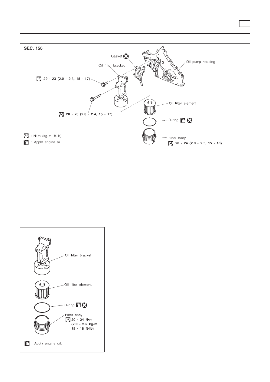
Oil Filter Bracket
NLLC0075
JLC301B
REMOVAL AND INSTALLATION
NLLC0075S01
1.
Remove the undercover.
2.
Steer the front wheel to the right.
3.
Remove the right splash cover.
4.
Remove the oil filter bracket bolt.
5.
Reinstall all removed parts in the reverse order of removal.
+
Insert the top mounting bolt to the oil filter bracket beforehand,
and set the oil filter bracket to the installation location.
JLC289B
Changing Oil Filter
NLLC0076
ENGINE LUBRICATION SYSTEM
YD
Oil Filter Bracket
LC-48
JLC290B
REMOVAL
NLLC0076S01
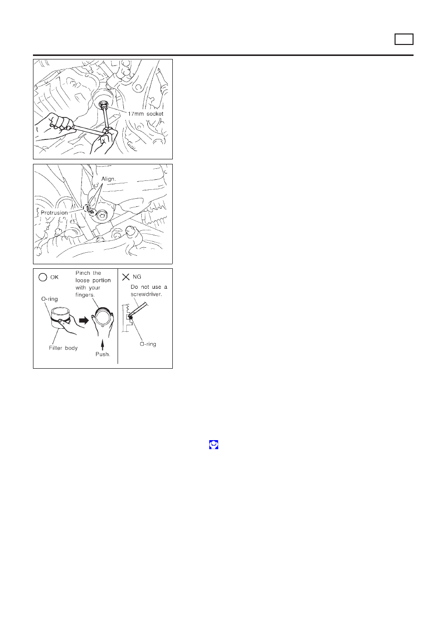
1.
Using a socket wrench [plane-to-plane width: 17 mm (0.67 in)],
loosen the filter body approximately four turns.
JLC291B
2.
Drain the oil after matching the “DRAIN” arrow mark at the
bottom of the filter body to the protrusion on the oil filter
bracket.
+
Catch the oil with a pan or cloth.
CAUTION:
+
The drained oil flows over the right surface of the filter
body.
+
Completely wipe clean any engine oil remaining on the
filter body or vehicle.
3.
Remove the filter body, then remove the oil filter element.
JLC292B
4.
Remove the O-ring from the filter body.
+
Push the O-ring in one direction, lift the slack part using
fingers, and remove the O-ring from the filter body.
CAUTION:
Do not use wires or flat-bladed screwdrivers etc. as they may
cause damage to the filter body.
INSTALLATION
NLLC0076S02
1.
Completely remove all foreign objects adhering to the inside of
the filter body or O-ring mounting area (body side and bracket
side).
2.
Install the oil filter element and O-ring to the filter body.
+
Push the oil filter element into the filter body completely.
3.
Install the filter body to the oil filter bracket.
: 20 - 24 N·m (2.0 - 2.5 kg-m, 15 - 18 ft-lb)
4.
After warming up the engine, check for engine oil leakage.
ENGINE LUBRICATION SYSTEM
YD
Changing Oil Filter (Cont’d)
LC-49
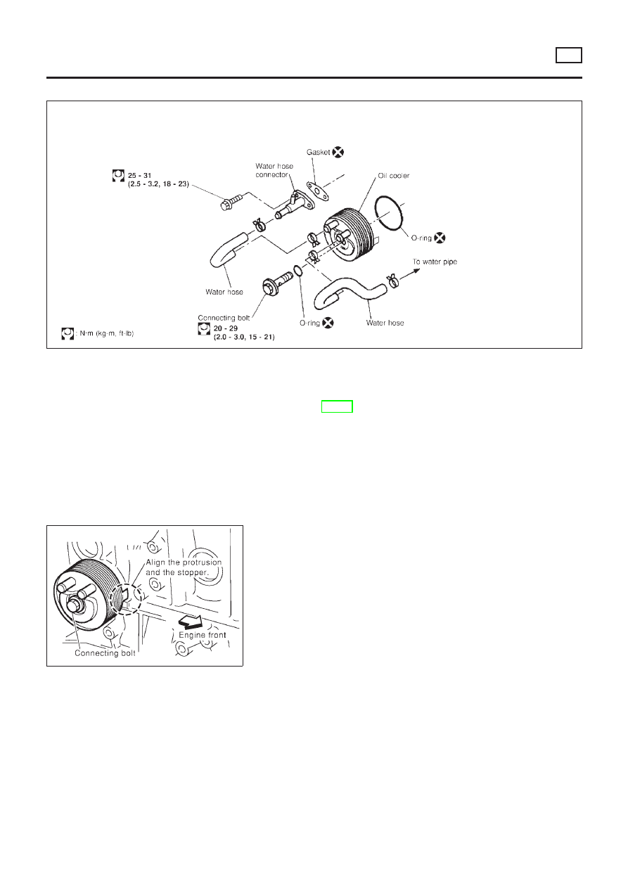
Oil Cooler
NLLC0077
NLC096
REMOVAL AND INSTALLATION
NLLC0077S01
1.
Draining the coolant
Refer to LC-59, “Changing Engine Coolant”.
2.
Remove the exhaust front tube.
SLC359B
3.
Reinstall all removed parts in the reverse order of removal.
+
Confirm that no foreign objects are adhering to the installation
planes of the oil cooler or block.
+
Tighten the connecting bolt after aligning the stopper on the
cylinder block side with protrusion of the oil cooler.
ENGINE LUBRICATION SYSTEM
YD
Oil Cooler
LC-50
Service Data and Specifications (SDS)
OIL PRESSURE CHECK
=NLLC0048
Engine speed
rpm
Approximate discharge pressure
kPa (bar, kg/cm
2
, psi)
Idle speed
More than 140 (1.40, 1.43, 20.3)
2,000
More than 270 (2.69, 2.75, 39.1)
4,000
More than 430 (4.29, 4.38, 62.3)
REGULATOR VALVE INSPECTION
NLLC0049
Unit: mm (in)
Regulator valve to oil pump cover clearance
0.040 - 0.097 (0.0016 - 0.0038)
OIL PUMP INSPECTION
NLLC0050
Unit: mm (in)
Body to outer rotor radial clearance
0.114 - 0.260 (0.0045 - 0.0102)
Inner rotor to outer rotor tip clearance
Below 0.18 (0.0071)
Body to inner rotor axial clearance
0.050 - 0.090 (0.0020 - 0.0035)
Body to outer rotor axial clearance
0.030 - 0.190 (0.0012 - 0.0075)
Inner rotor to brazed portion of housing clearance
0.045 - 0.091 (0.0018 - 0.0036)
ENGINE OIL CAPACITY
NLLC0078
Unit:
!
(Imp qt)
Drain and refill (Approximately)
Without oil filter change
4.9 (4-3/8)
With oil filter change
5.2 (4-5/8)
Dry engine (engine overhaul)
6.3 (5-1/2)
ENGINE LUBRICATION SYSTEM
YD
Service Data and Specifications (SDS)
LC-51

SEM164F
AEM080
Precautions
LIQUID GASKET APPLICATION PROCEDURE
NLLC0051
1.
Use a scraper to remove all traces of old liquid gasket from
mating surfaces and grooves. Also, completely clean any oil
from these areas.
2.
Apply a continuous bead of liquid gasket to mating surfaces.
(Use Genuine Liquid Gasket.)
+
For oil pan, be sure liquid gasket diameter is 4.0 to 5.0 mm
(0.157 to 0.197 in).
+
For areas except oil pan, be sure liquid gasket diameter is 2.0
to 3.0 mm (0.079 to 0.118 in).
3.
Apply liquid gasket around the inner side of bolt holes (unless
otherwise specified).
4.
Assembly should be done within 5 minutes after coating.
5.
Wait at least 30 minutes before refilling engine oil and engine
coolant.
Preparation
SPECIAL SERVICE TOOLS
NLLC0052
Tool number
Tool name
Description
EG17650301
Radiator cap tester
adapter
NT564
Adapting radiator cap tester to radiator filler neck
a: 28 (1.10) dia.
b: 31.4 (1.236) dia.
c: 41.3 (1.626) dia.
Unit: mm (in)
ENGINE COOLING SYSTEM
YD
Precautions
LC-52
Cooling Circuit
NLLC0053
SLC316B
ENGINE COOLING SYSTEM
YD
Cooling Circuit
LC-53
System Check
NLLC0054
WARNING:
Never remove the radiator cap when the engine is hot; serious
burns could be caused by high pressure fluid escaping from
the radiator.
Wrap a thick cloth around the cap and carefully remove it by
turning it a quarter turn to allow built-up pressure to escape
and then turn the cap all the way off.
CHECKING COOLING SYSTEM HOSES
NLLC0054S01
Check hoses for improper attachment, leaks, cracks, damage,
loose connections, chafing and deterioration.
CHECKING RADIATOR
NLLC0054S02
Check radiator for mud or clogging. If necessary, clean radiator as
follows.
+
Be careful not to bend or damage the radiator fins.
+
When radiator is cleaned without removal, remove all sur-
rounding parts such as cooling fan, radiator shroud and horns.
Then tape the harness and connectors to prevent water from
entering.
1.
Apply water by hose to the back side of the radiator core ver-
tically downward.
2.
Apply water again to all radiator core surfaces once per
minute.
3.
Stop washing if any stains no longer flow out from the radia-
tor.
4.
Blow air into the back side of radiator core vertically downward.
+
Use compressed air lower than 490 kPa (4.9 bar, 5 kg/cm
2
, 71
psi) and keep distance more than 30 cm (11.8 in).
5.
Blow air again into all the radiator core surfaces once per
minute until no water sprays out.
SLC755AC
CHECKING RADIATOR CAP
NLLC0054S03
To check radiator cap, apply pressure to cap with a tester.
Radiator cap relief pressure:
Standard
78 - 98 kPa
(0.78 - 0.98 bar, 0.8 - 1.0 kg/cm
2
, 11 - 14 psi)
Limit
59 - 98 kPa
(0.59 - 0.98 bar, 0.6 - 1.0 kg/cm
2
, 9 - 14 psi)
SMA967B
Pull the negative pressure valve to open it.
Check that it closes completely when released.
+
Check the radiator cap negative pressure valve for contamina-
tion or damage to the valve seat.
+
Move the negative pressure valve to check for abnormalities to
the opening/shutting operation.
CAUTION:
+
Be sure to perform the inspections after cooling down the
engine.
+
Before connecting the radiator cap to the tester, apply
water or LLC to the cap sealing.
ENGINE COOLING SYSTEM
YD
System Check
LC-54
+
Replace the radiator cap if abnormalities are found with the
negative pressure valve, or if the valve opening pressure is out
of the standard range.
SLC756AA
CHECKING COOLING SYSTEM FOR LEAKS
NLLC0054S04
To check for leakage, apply pressure to the cooling system with a
tester.
Testing pressure:
157 kPa (1.57 bar, 1.6 kg/cm
2
, 23 psi)
CAUTION:
+
Higher than the specified pressure may cause radiator
damage.
+
Be sure to perform the inspections after cooling down the
engine.
+
Use a hose adapter between the cap tester and filler neck
to prevent the radiator filler neck from deforming.
+
If any abnormalities are found, repair or replace the malfunc-
tioning parts.
Water Pump
REMOVAL AND INSTALLATION
NLLC0055
CAUTION:
+
When removing water pump assembly, be careful not to
get coolant on drive belt.
+
Water pump cannot be disassembled and should be
replaced as a unit.
+
After installing water pump, connect hose and clamp
securely, then check for leaks using radiator cap tester.
ENGINE COOLING SYSTEM
YD
System Check (Cont’d)
LC-55
JLC294B
REMOVAL
NLLC0056
1.
Remove the undercover, splash cover (right), and accessory
belt.
2.
Drain engine coolant. Refer to LC-59, “Changing Engine Cool-
ant”.
3.
Support the bottom of the oil pan with a floor jack etc., and
remove the right engine mount bracket (front side of the
engine).
4.
Remove the water pump pulley.
+
Loosen the pulley bolts after fixing the pulley using a screw-
driver etc.
5.
Remove engine mount brackets.
6.
Remove the water pump.
INSPECTION
NLLC0057
+
Check for rust and contamination adhering to the water pump
and vane.
+
Turn the pump shaft by hand, and check that the pump turns
smoothly without looseness.
INSTALLATION
NLLC0058
+
Install the parts in the reverse order of removal.
+
Install the water pump pulley with the front mark (painted white,
used to prevent errors during assembly) facing the front of the
engine. Refer to the figure above.
ENGINE COOLING SYSTEM
YD
Water Pump (Cont’d)
LC-56
Thermostat
REMOVAL AND INSTALLATION
NLLC0059
YLC012
+
Be careful not to spill coolant over engine compartment.
Use a rag to absorb coolant.
1.
Drain engine coolant. Refer to LC-59, “Changing Engine Cool-
ant”.
2.
Remove exhaust manifold cover.
3.
Remove water inlet.
4.
Remove thermostat.
JLC300B
5.
Install thermostat with jiggle valve facing upward.
+
Carefully install the rubber ring to the flange of the
thermostat, making sure it does not slip out of place.
6.
After installation and refilling coolant, run engine for a few
minutes, and check for leaks.
ENGINE COOLING SYSTEM
YD
Thermostat
LC-57
SLC252B
INSPECTION
NLLC0060
1.
Check valve seating condition at ordinary room temperatures.
It should seat tightly.
2.
Check valve opening temperature and maximum valve lift.
Standard
Valve opening temperature
Above 80 - 84°C (176 - 183°F)
Valve lift
More than 10 mm/95°C
(0.39 in/203°F)
3.
Then check if valve closes at 5°C (9°F) below valve opening
temperature.
Radiator
COMPONENTS
NLLC0083
NLC094
ENGINE COOLING SYSTEM
YD
Thermostat (Cont’d)
LC-58
REMOVAL AND INSTALLATION
NLLC0063
1. Remove under cover.
2. Drain coolant by removing lower radiator hose.
3. Disconnect radiator upper and lower hoses.
4. Remove radiator shroud.
5. Disconnect reservoir tank hose.
6. Remove radiator mounting bracket.
7. Remove radiator.
8. After repairing or replacing radiator, install any part removed in reverse order of removal.
When filling radiator with coolant, refer to LC-59, “Changing Engine Coolant”.
Cooling Fan
NLLC0064
COMPONENTS
NLLC0064S01
NLC095
CONTROL SYSTEM
Cooling fans are controlled by ECM. For details, refer to EC-1203,
“TROUBLE DIAGNOSIS FOR OVERHEAT”.
JLC295B
Changing Engine Coolant
NLLC0079
WARNING:
To avoid the danger of being scalded, never change the cool-
ant when the engine is hot.
— DRAINING ENGINE COOLANT —
NLLC0079S01
1.
Set air conditioning system as follows to prevent coolant from
remaining in the system.
a.
Turn ignition switch ON and set temperature controller to maxi-
mum hot position.
b.
Wait 10 seconds before turning ignition switch OFF.
ENGINE COOLING SYSTEM
YD
Radiator (Cont’d)
LC-59
SMA033D
2.
Remove lower radiator hose, and remove radiator filler cap to
drain coolant.
3.
Remove reservoir tank, drain coolant, then clean reservoir
tank.
+
Be careful not to allow coolant to contact drive belts.
4.
Cover the exhaust tube heat shield to prevent from splashing
coolant.
YLC013
SLC341B
5.
Remove drain plug of cylinder block and air relief plug.
6.
Check drained coolant for contaminants such as rust, corro-
sion or discoloration. If contaminated flush engine cooling
system, refer to LC-61, “FLUSHING COOLING SYSTEM”.
7.
Blow the coolant around the exhaust tube heat shield.
JLC298B
— REFILLING ENGINE COOLANT —
NLLC0079S02
1.
Install reservoir tank, lower radiator hose and cylinder block
drain plug.
+
Apply sealant to the thread of cylinder block drain plugs.
: 8 - 11 N·m (0.8 - 1.2 kg-m, 70 - 104 in-lb)
2.
Fill radiator slowly with coolant until coolant spills from the air
relief plugs, then install air relief plugs.
+
Location of air relief plugs
Water inlet (where fitted) and rear side intake manifold water
tubes
+
Fill coolant to the level of the radiator cap at a rate of 2
!
(1-3/4
Imp qt)/min or lower.
(Close the plugs in order starting with the location from where
the coolant began spilling out.)
CAUTION:
If the filling rate is too fast, this could lead to air being mixed
in the coolant. Be sure to fill the coolant slowly according to
the rate indicated above.
+
Replace the copper washer of the air bleeding plug.
Air relief plug:
: 6.7 - 7.9 N·m (0.68 - 0.81 kg-m, 59 - 70 in-lb)
+
Use genuine Nissan anti-freeze coolant or equivalent.
ENGINE COOLING SYSTEM
YD
Changing Engine Coolant (Cont’d)
LC-60
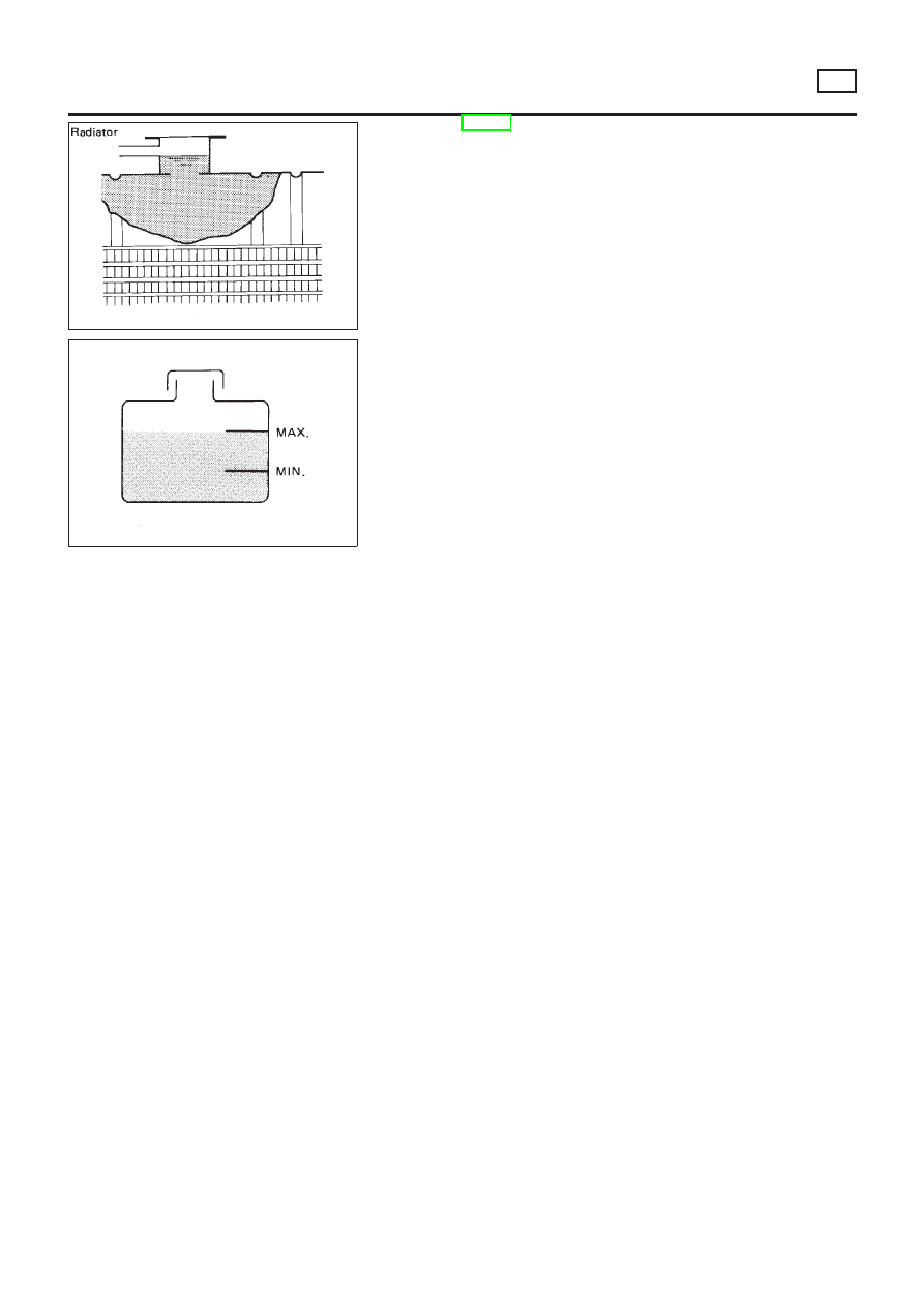
SMA182B
SMA412B
Refer to MA-20, “RECOMMENDED FLUIDS AND LUBRI-
CANTS”.
Engine coolant capacity (With reservoir tank):
7.05
!
(6–1/4 Imp qt)
Reservoir tank capacity:
0.7
!
(5/8 Imp qt)
+
Pour coolant through coolant filler neck slowly to allow air
in system to escape.
3.
Fill radiator and reservoir tank to specified level.
4.
Warm up engine to normal operating temperature without
radiator cap installed.
+
If coolant overflows radiator filler hole, install radiator cap.
5.
Run engine at 3,000 rpm for 10 seconds and return to idle
speed with radiator cap installed.
+
Repeat two or three times.
Watch coolant temperature gauge so as not to overheat the
engine.
6.
Stop engine and cool it down.
+
Cool down using a fan to reduce the time.
+
If necessary, refill radiator up to filler neck with coolant.
7.
Refill reservoir tank to MAX level line with coolant.
8.
Repeat steps 4 through 7 two or more times with radiator cap
installed until coolant level no longer drops.
9.
Check cooling system for leaks with engine running.
10. Warm up engine, and check for sound of coolant flow while
running engine from idle up to 3,000 rpm with heater tempera-
ture controller set at several positions between COOL and
HOT.
+
Sound may be noticeable at heater water cock.
11. If sound is heard, bleed air from cooling system by repeating
steps 4 through 7 until coolant level no longer drops
+
Clean excess coolant from engine.
— FLUSHING COOLING SYSTEM —
NLLC0079S03
1.
Open air relief plug.
2.
Fill radiator with water until water spills from the air relief hole,
then close air relief plug. Fill radiator and reservoir tank with
water and reinstall radiator cap.
3.
Run engine and warm it up to normal operating temperature.
4.
Rev engine two or three times under no-load.
5.
Stop engine and wait until it cools down.
6.
Drain water.
7.
Repeat steps 1 through 6 until clear water begins to drain from
radiator.
ENGINE COOLING SYSTEM
YD
Changing Engine Coolant (Cont’d)
LC-61
Overheating Cause Analysis
NLLC0070
Symptom
Check items
Cooling sys-
tem parts
malfunction
Poor heat transfer
Water pump malfunction
Worn or loose drive belt
—
Thermostat stuck closed
—
Damaged fins
Dust contamination or
paper clogging
Mechanical damage
Clogged radiator cooling
tube
Excess foreign material
(rust, dirt, sand, etc.)
Reduced air flow
Cooling fan does not oper-
ate
—
—
High resistance to fan rota-
tion
Damaged fan blades
Damaged radiator shroud
—
—
—
Improper coolant mixture
ratio
—
—
—
Poor coolant quality
—
—
—
Insufficient coolant
Coolant leaks
Cooling hose
Loose clamp
Cracked hose
Water pump
Poor sealing
Radiator cap
Loose
Poor sealing
Radiator
O-ring for damage, dete-
rioration or improper fit-
ting
Cracked radiator tank
Cracked radiator core
Reservoir tank
Cracked reservoir tank
Overflowing reservoir tank
Exhaust gas leaks into
cooling system
Cylinder head deteriora-
tion
Cylinder head gasket
deterioration
ENGINE COOLING SYSTEM
YD
Overheating Cause Analysis
LC-62
Symptom
Check items
Except cool-
ing system
parts mal-
function
—
Overload on engine
Abusive driving
High engine rpm under
no load
Driving in low gear for
extended time
Driving at extremely high
speed
Powertrain system malfunc-
tion
—
Installed improper size
wheels and tires
Dragging brakes
Improper ignition timing
Blocked or restricted air
flow
Blocked bumper
—
—
Blocked radiator grille
Installed car brassiere
Mud contamination or
paper clogging
Blocked radiator
—
Blocked condenser
—
Installed large fog lamp
Service Data and Specifications (SDS)
THERMOSTAT
NLLC0071
Valve opening temperature
Above 80 - 84°C (176 - 183°F)
Valve lift
More than 10 mm/95°C (0.394 in/203°F)
RADIATOR
NLLC0073
Unit: kPa (bar, kg/cm
2
, psi)
Cap relief pressure
Standard
78 - 98 (0.78 - 0.98, 0.8 - 1.0, 11 - 14)
Limit
59 - 98 (0.59 - 0.98, 0.6 - 1.0, 9 - 14)
Leakage test pressure
157 (1.57, 1.6, 23)
ENGINE COOLANT CAPACITY
NLLC0080
Unit:
!
(Imp qt)
With reservoir tank
7.05 (6-1/4)
Reservoir tank
0.7 (5/8)
ENGINE COOLING SYSTEM
YD
Overheating Cause Analysis (Cont’d)
LC-63

ENGINE COOLING SYSTEM
Service Data and Specifications (SDS) (Cont’d)
LC-64
Document Outline
- Quick Reference Index
- Table of Contents
- QG
- ENGINE LUBRICATION SYSTEM
- ENGINE COOLING SYSTEM
- SR
- ENGINE LUBRICATION SYSTEM
- ENGINE COOLING SYSTEM
- YD
- ENGINE LUBRICATION SYSTEM
- ENGINE COOLING SYSTEM
Wyszukiwarka
Podobne podstrony:
Automotive Engine Lubrication & Cooling Systems
EVAPORATIVE COOLING SYSTEMS
5 Cooling System
05 cooling system
Popular Mechanics Flushing Your Cooling System
Popular Mechanics Repairing Cooling System Leaks
COOLING SYSTEM
G 2 0 DOHC Cooling System Repair doc
general cooling system servicing
Tab6 M73TU&M62TU Cooling Systems
cooling system specifications
Group 08 Engine Lubrication
05 cooling system
5 Cooling System
03 Engine Cooling Heating System
4 Fuel and Lubrication System
więcej podobnych podstron