(QJLQH0HFKDQLFDO
Special Tools .............................................................................................................................................................. 08-2
Component Location Index ........................................................................................................................................ 08-3
Oil Pressure Switch Test ............................................................................................................................................ 08-4
Oil Pressure Test ........................................................................................................................................................ 08-4
Engine Oil Replacement ............................................................................................................................................ 08-5
Engine Oil Filter Replacement ................................................................................................................................... 08-6
Oil Filter Holder Replacement .................................................................................................................................... 08-9
Oil Pump Overhaul ................................................................................................................................................... 08-10
Oil Pressure Switch Replacement............................................................................................................................ 08-18
(QJLQH0HFKDQLFDO
(QJLQH/XEULFDWLRQ
(QJLQH/XEULFDWLRQ
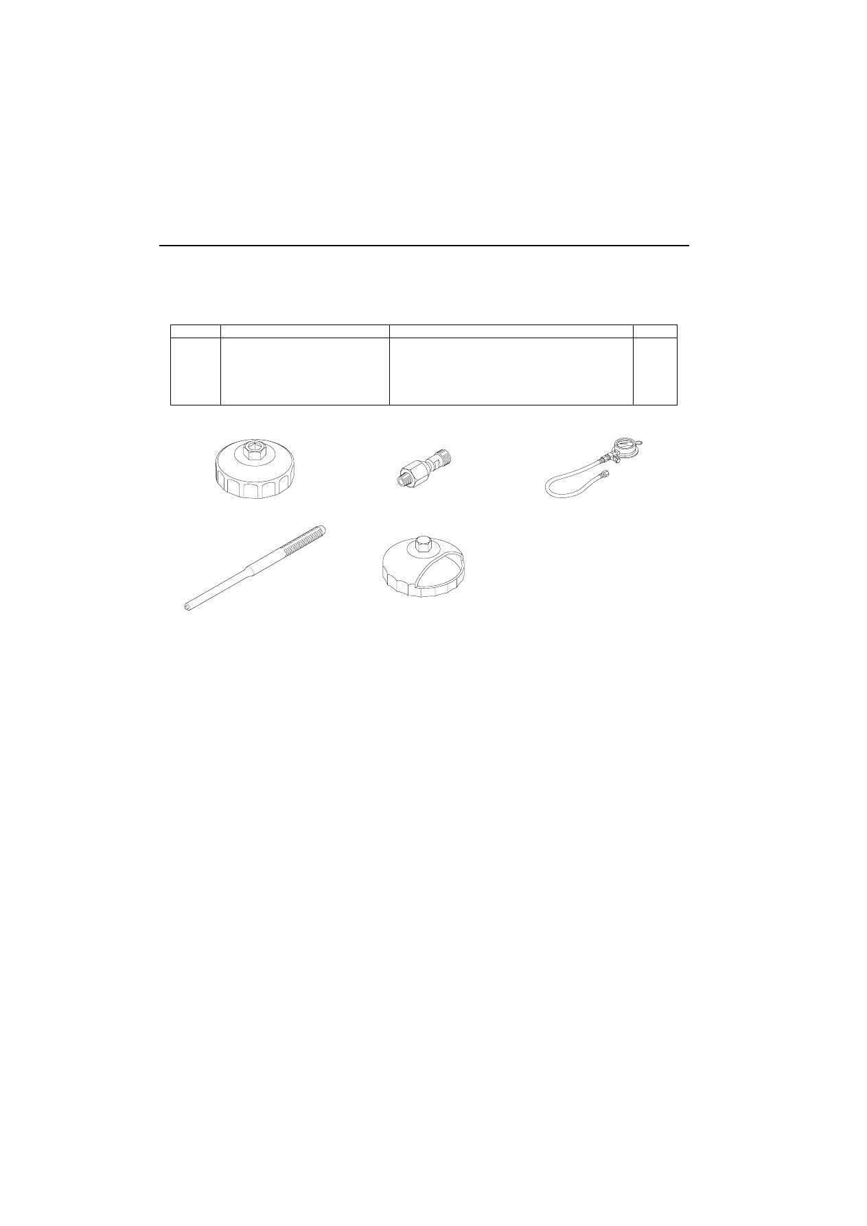
6SHFLDO7RROV
5HI1R
7RRO1XPEHU
'HVFULSWLRQ
4W\
07HAA-PJ70100
Oil Filter Wrench
1
07406-0030000
Oil Pressure Gauge Attachment
1
07506-3000001
Oil Pressure Gauge
1
07744-0010500
Pin Driver, 6.0 mm
1
07912-6110001
Oil Filter Wrench
1
(QJLQH/XEULFDWLRQ
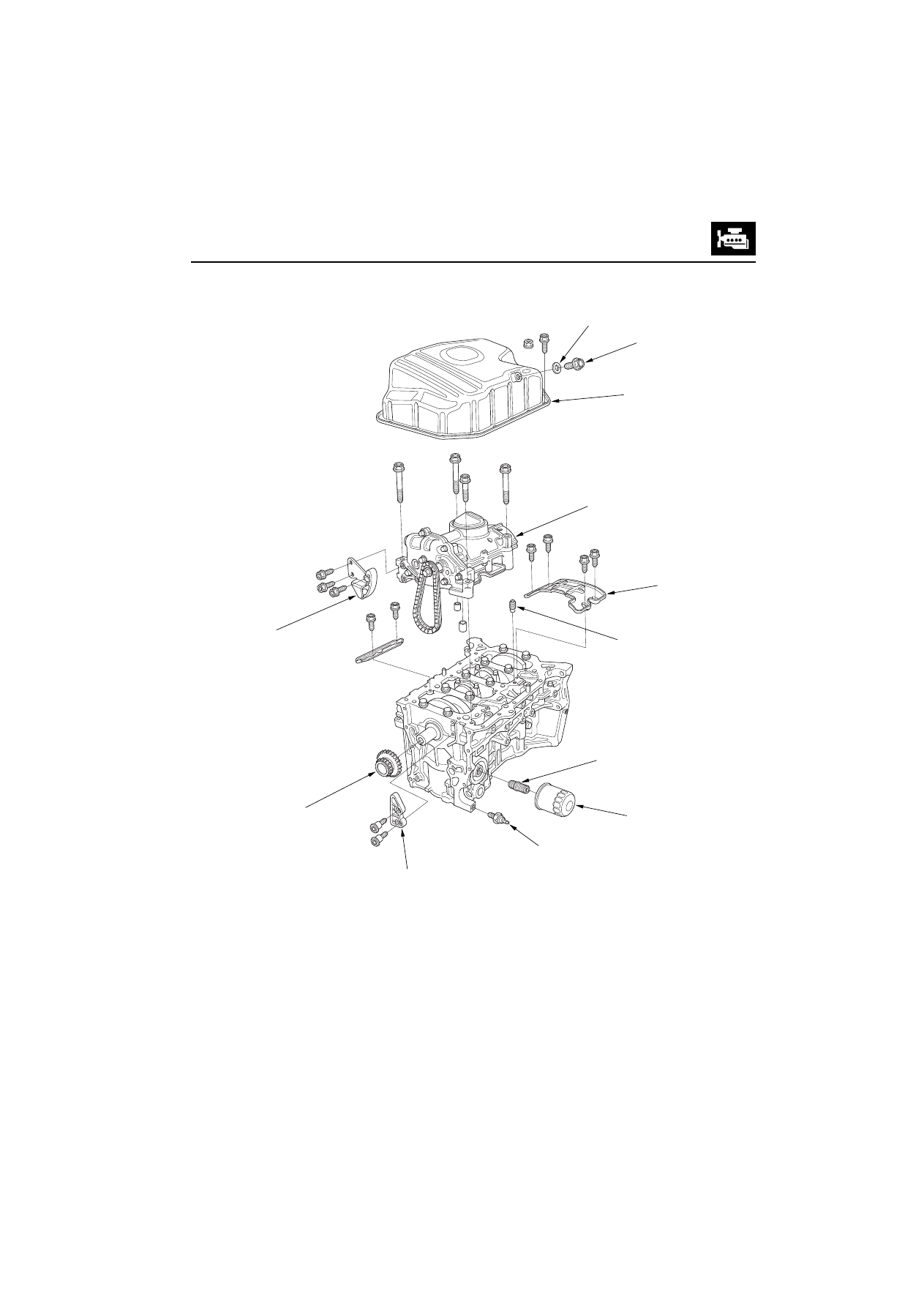
&RPSRQHQW/RFDWLRQ,QGH[
2,/3$1
Removal,
2,/3803
Overhaul,
2,/),/7(5+2/'(5
2,/),/7(5
2,/35(6685(6:,7&+
Circuit Diagram,
; Oil Pressure test,
;
:$6+(5
'5$,1%2/7
%$))/(3/$7(
2,/&21752/
25,),&(
2,/3803&+$,1
7(16,21(5
&5$1.6+$)7
6352&.(7
2,/3803&+$,1*8,'(
(QJLQH0HFKDQLFDO
(QJLQH/XEULFDWLRQ
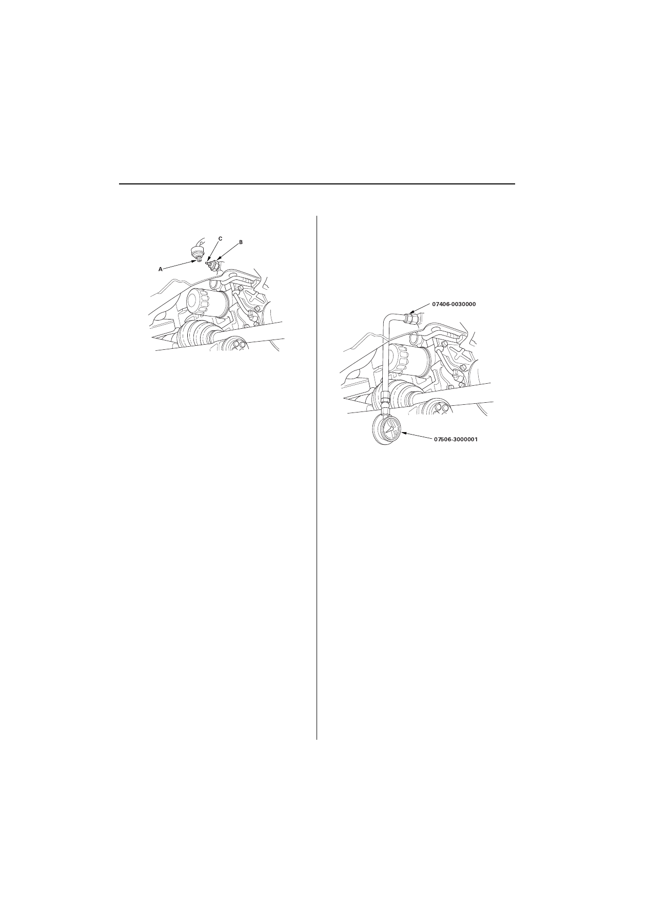
2LO3UHVVXUH6ZLWFK7HVW
Remove the YEL/RED wire (A) from the engine oil
pressure switch (B).
Check for continuity between the positive terminal
(C) and the engine (ground). There should be
continuity with the engine stopped. There should
be no continuity with the engine running.
If the switch fails to operate, check the engine oil
level. If the engine oil level is OK, check the engine
oil pressure. If the oil pressure is OK, replace the oil
pressure switch.
2LO3UHVVXUH7HVW
6SHFLDO7RROV5HTXLUHG
Oil pressure gauge attachment 07406-0030000
Oil pressure gauge 07506-3000001
If the oil pressure warning light stays on with the engine
running, check the engine oil level. If the oil level is correct:
Connect a tachometer or a Honda PGM Tester.
Remove the engine oil pressure switch, and install
an the special tools.
Start the engine. Shut it off immediately if the
gauge registers no oil pressure. Repair the problem
before continuing.
Allow the engine to reach operating temperature
(fan comes on at least twice). The pressure should
be:
(QJLQH2LO7HPSHUDWXUH&)
(QJLQH2LO3UHVVXUH
$W,GOH
N3DNJIFP
SVL
PLQLPXP
$WUSP N3DNJIFP
SVL
PLQ
PLQLPXP
If the oil pressure is NOT within specifications,
inspect these items.
Check the oil screen for clogging.
Check the oil pump
(QJLQH/XEULFDWLRQ
(QJLQH2LO5HSODFHPHQW
Warm up the engine.
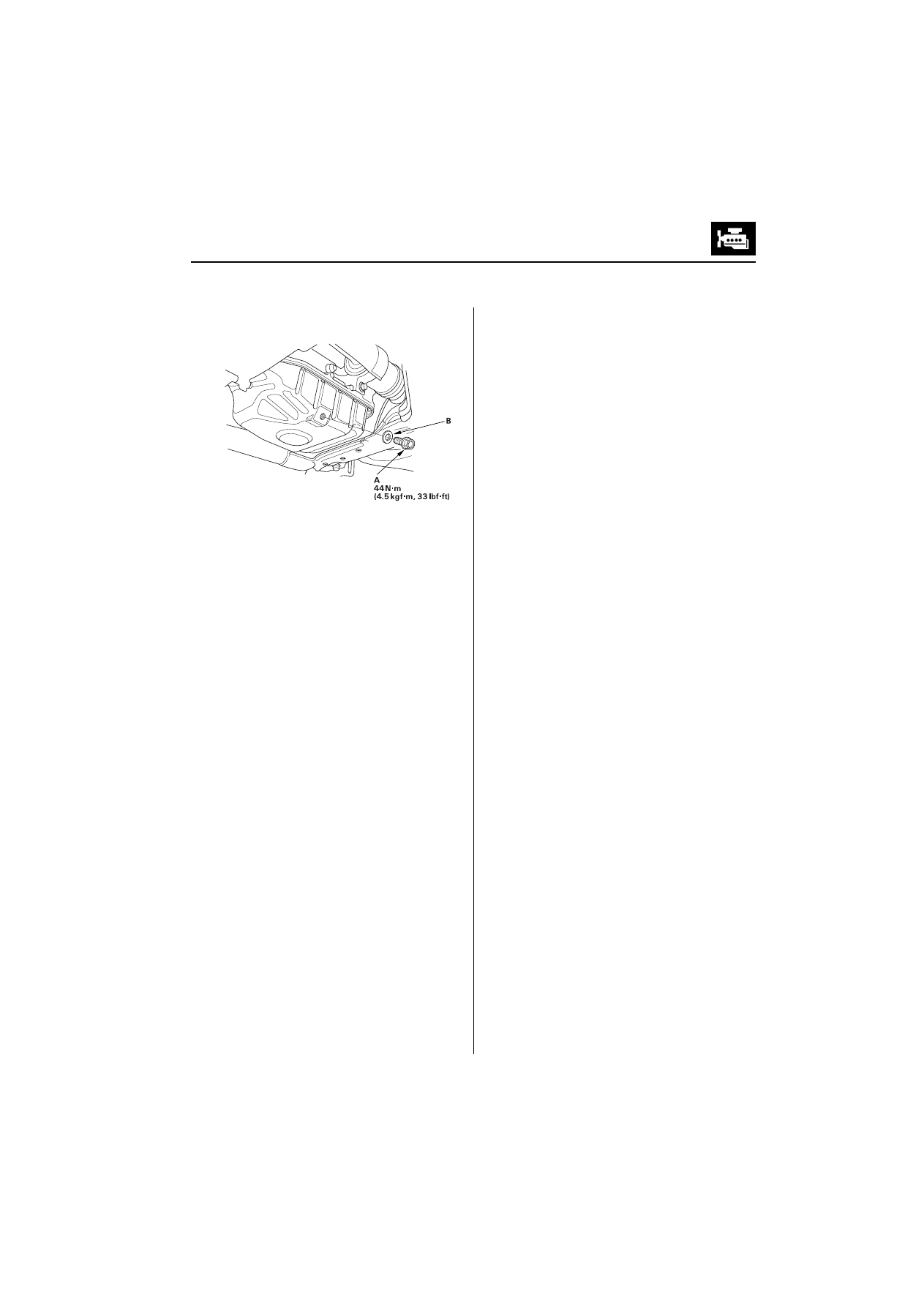
Remove the drain bolt (A), and drain the engine oil.
Reinstall the drain bolt with a new washer (B).
Refill with the recommended oil
.
&DSDFLW\
O
86TWOPSTWDWRLOFKDQJH
O
86TWOPSTWDWRLOFKDQJH
LQFOXGLQJILOWHU
O
86TWOPSTWDIWHUHQJLQHRYHUKDXO
Run the engine for more than 3 minutes, then
check for oil leakage.
Do not overtighten.
(QJLQH0HFKDQLFDO
(QJLQH/XEULFDWLRQ
(QJLQH2LO)LOWHU5HSODFHPHQW
6SHFLDO7RROV5HTXLUHG
Oil filter wrench 07HAA-PJ70100
Oil filter wrench 07912-6110001
-$3$10$'((QJLQH2LO)LOWHU
WXUQW\SH
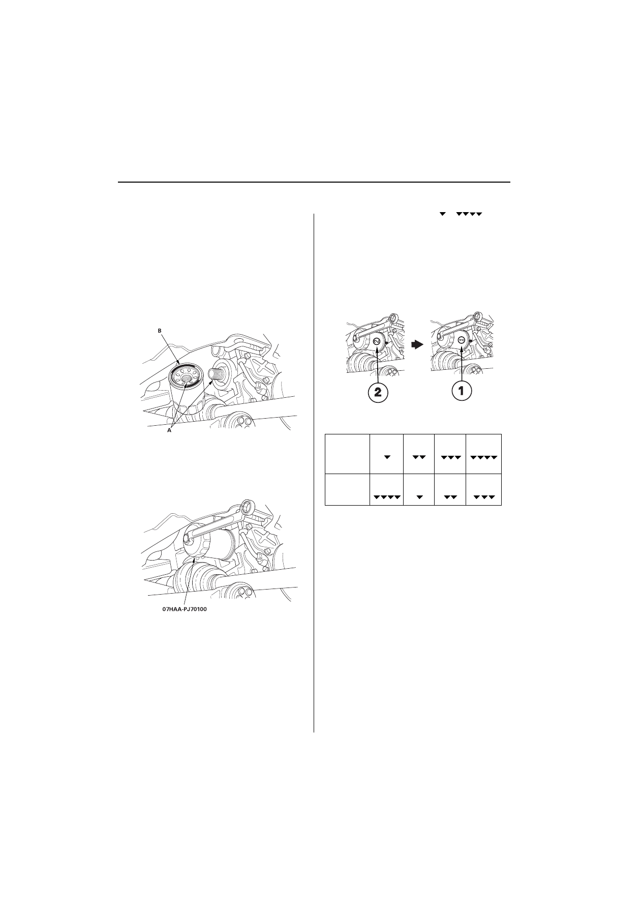
Remove the oil filter with the special oil filter
wrench.
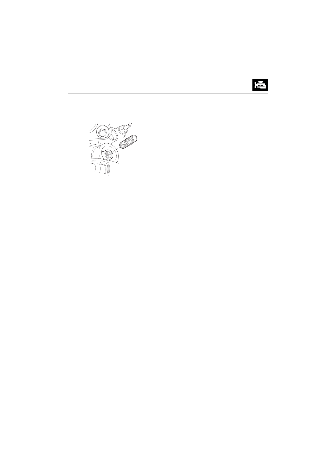
Inspect the threads (A) and rubber seal (B) on the
new filter. Wipe off the seat on the engine block,
then apply a light coat of oil to the filter rubber seal.
Use only filters with a built-in bypass system.
Install the oil filter by hand.
After the rubber seal seats, tighten the oil filter
clockwise with the special tool.
7LJKWHQ
WXUQFORFNZLVH
7LJKWHQLQJWRUTXH
1
·
PNJI
·
POEI
·
IW
If 4 numbers or marks (1 to 4 or
to
) are
printed around the outside of the filter, use the
following procedure to tighten the filter.
Spin the filter on until its seal lightly seats against
the block, and note which number or mark is at the
bottom.
Tighten the filter by turning it clockwise 3 numbers
or marks from the one you noted. For example, if
number 2 is at the bottom when the seal is seated,
tighten the filter until the number 1 comes around
the bottom.
After installation, fill the engine with oil up to the
specified level, run the engine for more than 3
minutes, then check for oil leakage.
Number or
Mark when
rubber seal
is seated
1
or
2
or
3
or
4
or
Number or
Mark after
tightening
4
or
1
or
2
or
3
or
1XPEHUZKHQUXEEHU
VHDOLVVHDWHG
1XPEHUDIWHUWLJKWHQLQJ
(QJLQH/XEULFDWLRQ
-$3$10$'((QJLQH2LO)LOWHU
WXUQW\SH
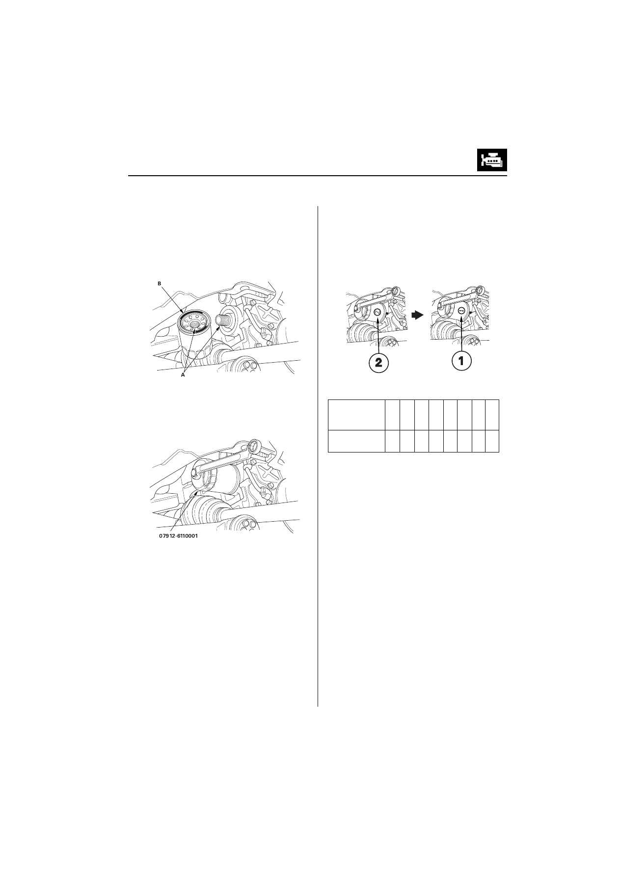
Remove the oil filter with the special oil filter
wrench.
Inspect the threads (A) and rubber seal (B) on the
new filter. Wipe off the seat on the engine block,
then apply a light coat of oil to the filter rubber seal.
Use only filters with a built-in bypass system.
Install the oil filter by hand.
After the rubber seal seats, tighten the oil filter
clockwise with the special tool.
7LJKWHQ
WXUQFORFNZLVH
7LJKWHQLQJWRUTXH
1
·
PNJI
·
POEI
·
IW
If 8 numbers (1 to 8) are printed around the outside
of the filter, use the following procedure to tighten
the filter.
Spin the filter on until its seal lightly seats against
the block, and note which number is at the bottom.
Tighten the filter by turning it clockwise 7 numbers
from the one you noted. For example, if number 2 is
at the bottom when the seal is seated, tighten the
filter until the number 1 comes around the bottom.
After installation, fill the engine with oil up to the
specified level, run the engine for more than 3
minutes, then check for oil leakage.
(cont’d)
Number when
rubber seal is
seated
1
2
3
4
5
6
7
8
Number after
tightening
8
1
2
3
4
5
6
7
1XPEHUZKHQUXEEHU
VHDOLVVHDWHG
1XPEHUDIWHUULJKWHQLQJ
(QJLQH0HFKDQLFDO
(QJLQH/XEULFDWLRQ
(QJLQH2LO)LOWHU5HSODFHPHQWFRQW¶G
)5$1&(0$'((QJLQH2LO)LOWHU
WXUQW\SH
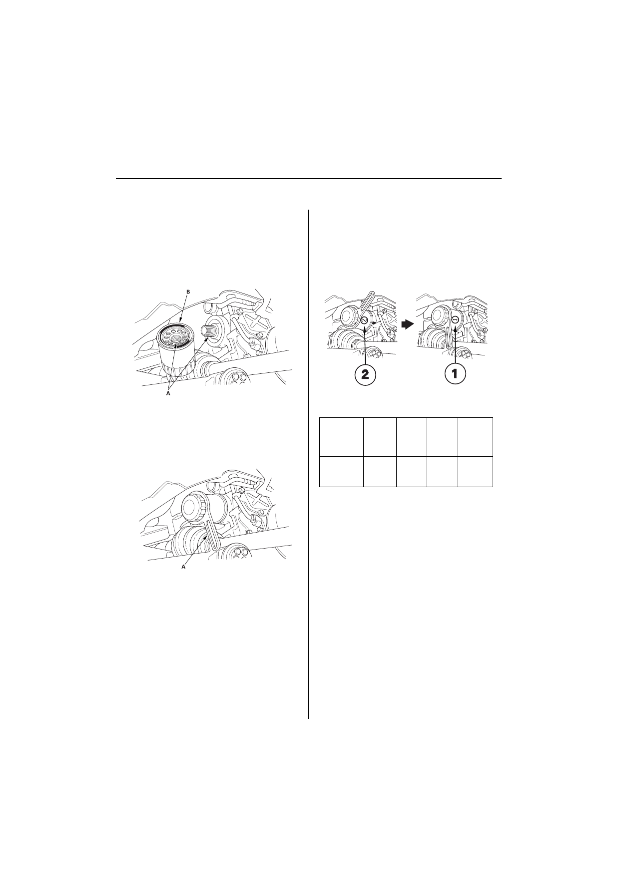
Remove the oil filter with the commercially
available oil filter wrench (LABINAL-Purflux 76).
Inspect the threads (A) and rubber seal (B) on the
new filter. Wipe off the seat on the engine block,
then apply a light coat of oil to the filter rubber seal.
Use only filters with a built-in bypass system.
Install the oil filter by hand.
After the rubber seal seats, tighten the oil filter
clockwise with the commercially available oil filter
wrench (LABINAL-Purflux 76)(A).
7LJKWHQ
WXUQFORFNZLVH
7LJKWHQLQJWRUTXH
1
·
PNJI
·
POEI
·
IW
If 4 numbers (1 to 4) are printed around the outside
of the filter, use the following procedure to tighten
the filter.
Spin the filter on until its seal lightly seats against
the block, and note which number is at the bottom.
Tighten the filter by turning it clockwise 3 numbers
from the one you noted. For example, if number 2 is
at the bottom when the seal is seated, tighten the
filter until the number 1 comes around the bottom.
After installation, fill the engine with oil up to the
specified level, run the engine for more than 3
minutes, then check for oil leakage.
Number or
Mark when
rubber seal
is seated
1
2
3
4
Number or
Mark after
tightening
4
1
2
3
1XPEHUZKHQUXEEHU
VHDOLVVHDWHG
1XPEHUDIWHUWLJKWHQLQJ
(QJLQH/XEULFDWLRQ
2LO)LOWHU+ROGHU5HSODFHPHQW
Remove the oil filter
.
Remove the oil filter holder.
Tighten the new oil filter holder to 49 N·m (5.0
kgf·m, 36 lbf·ft)
(QJLQH0HFKDQLFDO
(QJLQH/XEULFDWLRQ
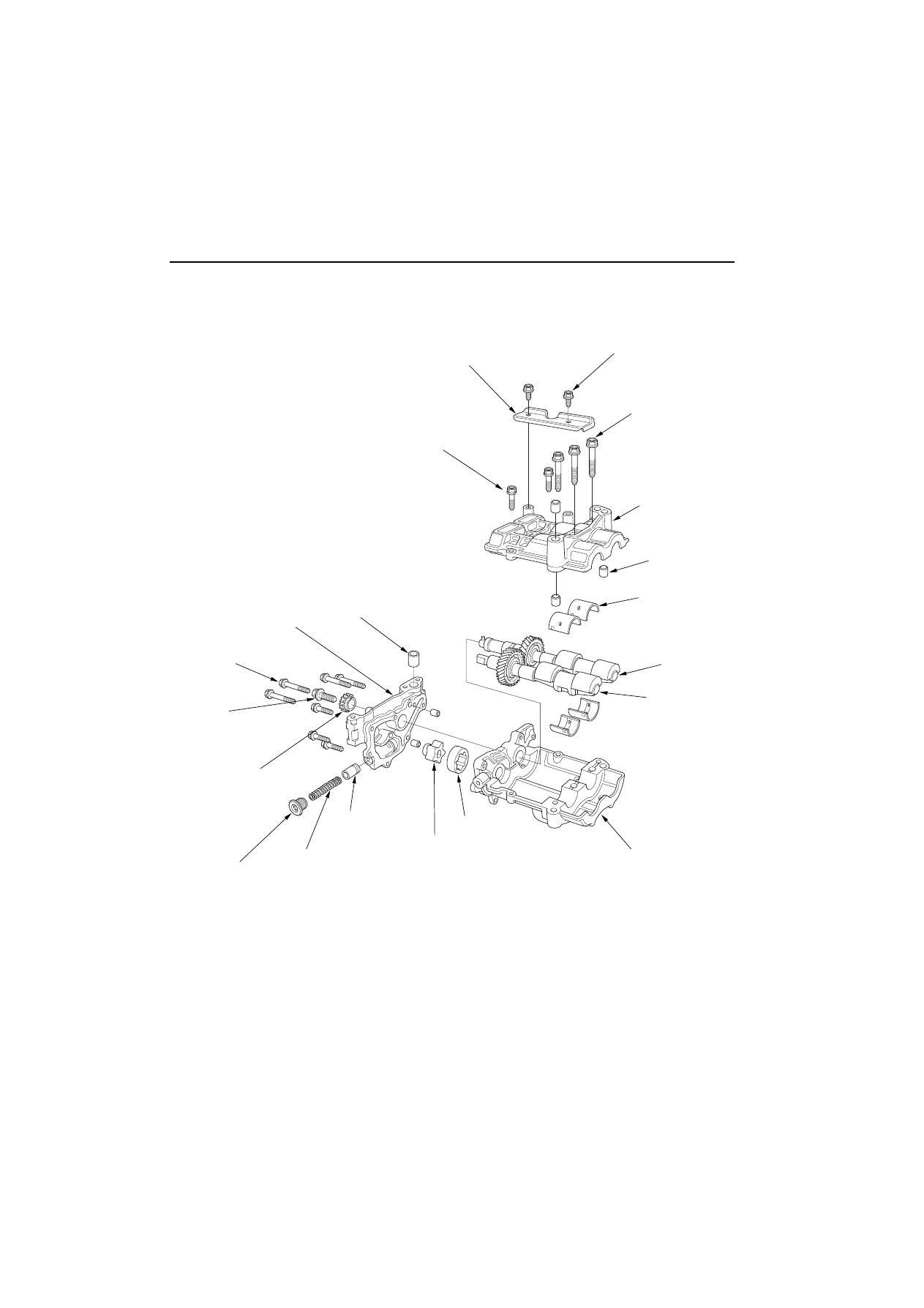
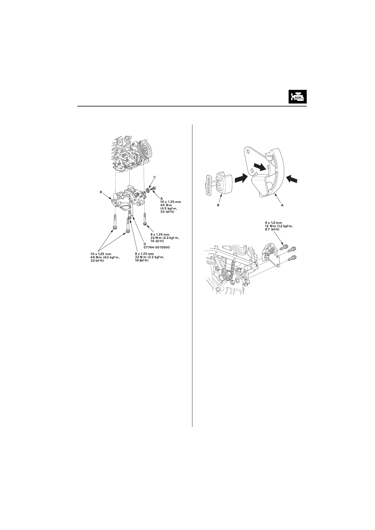
2LO3XPS2YHUKDXO
([SORGHG9LHZ
%$))/(3/$7(
[PP
1·P
NJI·POEI·IW
'2:(/3,1
3803+286,1*
[PP
1·P
NJI·POEI·IW
[PP
1·P
NJI·POEI·IW
Apply engine oil to the bolt
threads.
2,/38036352&.(7
635,1*
6($/,1*%2/7
1·P
NJI·POEI·IW
5(/,()9$/9(
Valve must slide freely in
housing bore. Replace if
scored.
,11(552725
287(552725
/2:(5%$/$1&(5
6+$)7+2/'(5
)5217
%$/$1&(5
6+$)7
5($5
%$/$1&(5
6+$)7
'2:(/3,1
[PP
1·P
NJI·POEI·IW
833(5%$/$1&(5
6+$)7+2/'(5
[PP
1·P
NJI·POEI·IW
Apply engine oil to the
bolt threads.
%$/$1&(56+$)7
%($5,1*6
(QJLQH/XEULFDWLRQ
6SHFLDO7RROV5HTXLUHG
Pin driver, 6.0 mm 07744-0010500
2LO3XPS5HPRYDO
Set the No. 1 piston at Top Dead Center (TDC)
(see step 1 on
Remove the oil pan
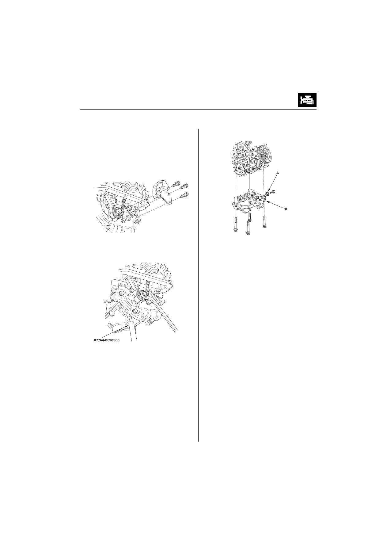
Remove the oil pump chain tensioner.
To hold the rear balancer shaft, insert a pin driver
into the hole in the rear balancer shaft, through the
maintenance hole on the lower balancer shaft
holder.
Loosen the oil pump sprocket mounting bolt.
Remove the oil pump sprocket (A), then remove
the oil pump (B).
(cont’d)
(QJLQH0HFKDQLFDO
(QJLQH/XEULFDWLRQ
2LO3XPS2YHUKDXOFRQW¶G
2LO3XPS,QVSHFWLRQ
Remove the pump housing.
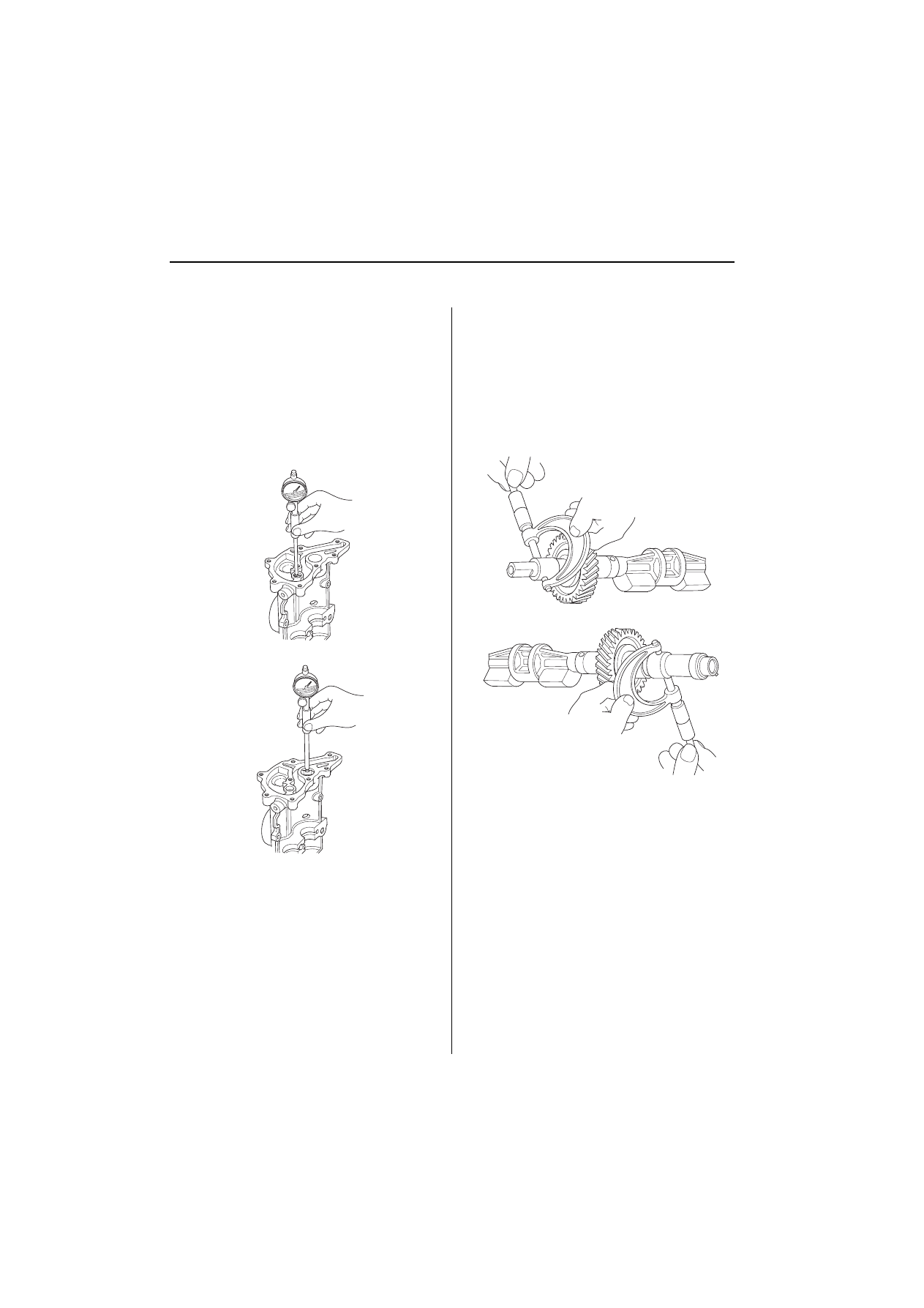
Check the inner-to-outer rotor radial clearance
between the inner rotor (A) and outer rotor (B). If
the inner-to-outer rotor radial clearance exceeds
the service limit, replace the oil pump.
,QQHU5RWRUWR2XWHU5RWRU5DGLDO&OHDUDQFH
6WDQGDUG1HZPPLQ
6HUYLFH/LPLW
PPLQ
Check the housing-to-rotor axial clearance
between the rotor (A) and pump housing (B). If the
housing-to-rotor axial clearance exceeds the
service limit, replace the oil pump.
+RXVLQJWR5RWRU$[LDO&OHDUDQFH
6WDQGDUG1HZ PPLQ
6HUYLFH/LPLW
PPLQ
Check the housing-to-outer rotor radial clearance
between the outer rotor (A) and pump housing (B).
If the housing-to-outer rotor radial clearance
exceeds the service limit, replace the oil pump.
+RXVLQJWR2XWHU5RWRU5DGLDO&OHDUDQFH
6WDQGDUG1HZ PPLQ
6HUYLFH/LPLW
PPLQ
Inspect both rotors and the pump housing for
scoring or other damage. Replace parts if
necessary.
(QJLQH/XEULFDWLRQ
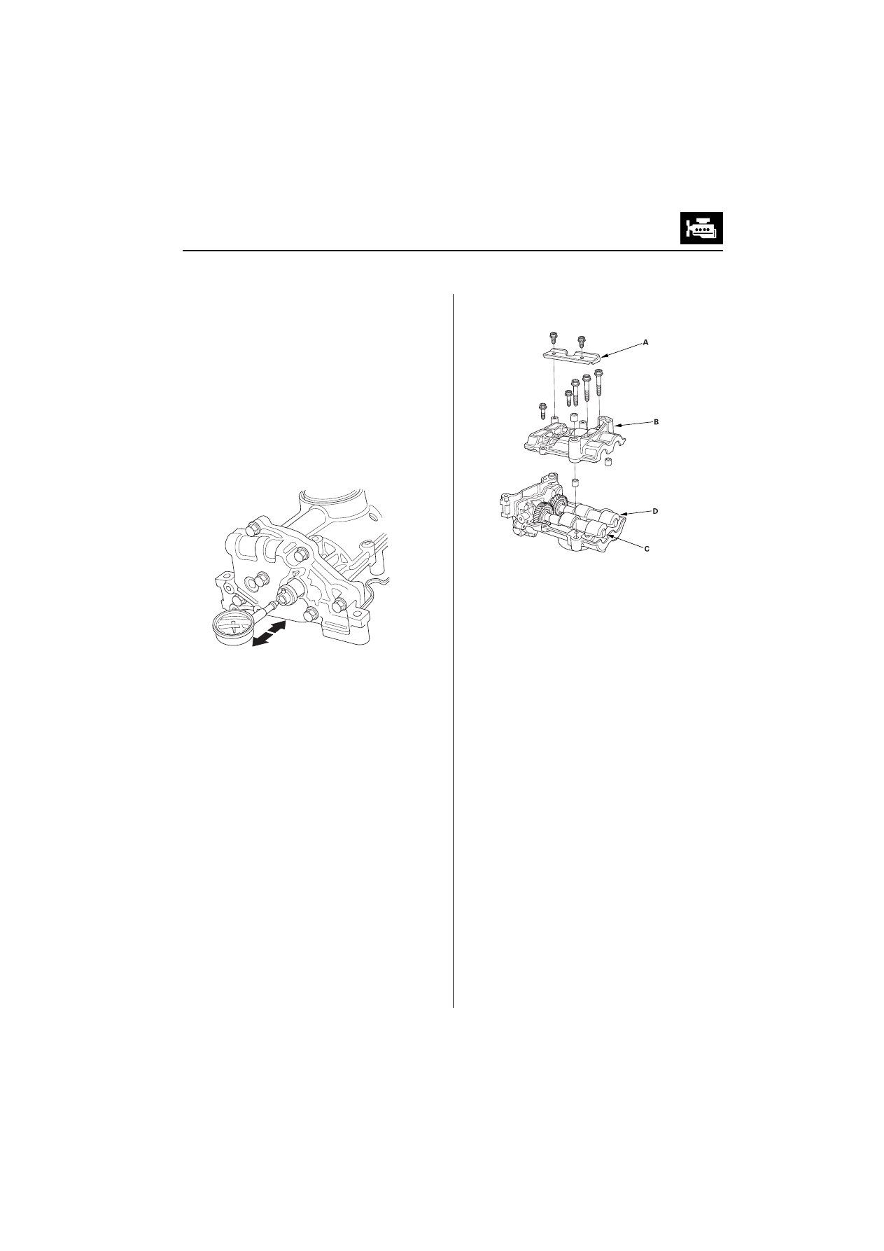
%DODQFHU6KDIW,QVSHFWLRQ
Seat the balancer shaft by pushing it away from the
oil pump sprocket end of the oil pump.
Zero the dial indicator against the end of the
balancer shaft, then push the balancer shaft back
and forth and read the end play.
%DODQFHU6KDIW(QG3OD\
)URQW%DODQFHU6KDIW
6WDQGDUG1HZ PP
LQ
6HUYLFH/LPLW
PPLQ
5HDU%DODQFHU6KDIW
6WDQGDUG1HZ
PP
LQ
6HUYLFH/LPLW
PPLQ
Remove the baffle plate (A) and upper balancer
shaft holder (B), then remove the front balancer
shaft (C) and rear balancer shaft (D).
(cont’d)
(QJLQH0HFKDQLFDO
(QJLQH/XEULFDWLRQ
2LO3XPS2YHUKDXOFRQW¶G
Measure the inner diameter of the No. 1 bearing for
the front balancer shaft hole and the rear balancer
shaft hole.
%HDULQJ,QQHU'LDPHWHU
)URQW
6WDQGDUG1HZ PP
LQ
6HUYLFH/LPLW
PPLQ
5HDU
6WDQGDUG1HZ PP
LQ
6HUYLFH/LPLW
PPLQ
)URQW
5HDU
Measure the diameters of the No. 1 journals on the
front balancer shaft and rear balancer shaft.
-RXUQDO'LDPHWHU
)URQW
6WDQGDUG1HZ PP
LQ
6HUYLFH/LPLW
PPLQ
5HDU
6WDQGDUG1HZ PP
LQ
6HUYLFH/LPLW
PPLQ
)URQW
5HDU
(QJLQH/XEULFDWLRQ
Clean each balancer shaft No. 2 journals and
bearings half with a clean shop towel.
Place one strip of plastigage across each journal.
Reinstall the bearings and upper balancer shaft
holder, the torque the bolts.
NOTE: Do not rotate the balancer shaft during
inspection.
Remove the upper balancer shaft holder and
bearings again, and measure the widest part of the
plastigage.
If the balancer shaft No. 2 journal oil clearance is out-
of-tolerance, install the new bearings, and recheck. If
it is still out-of-tolerance; replace the balancer shafts.
1R-RXUQDO2LO&OHDUDQFH
6WDQGDUG1HZ
PP
LQ
6HUYLFH/LPLW
PPLQ
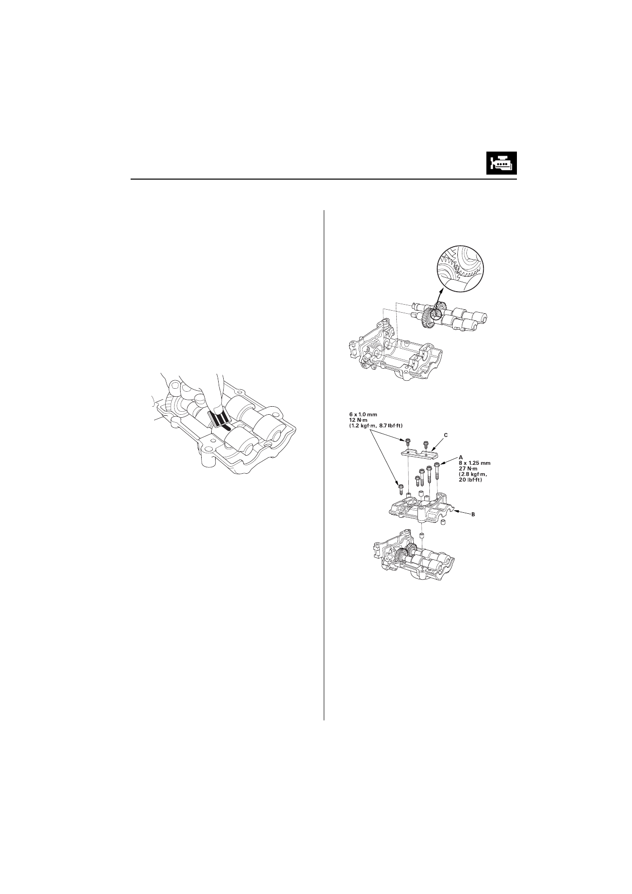
Align the punch mark on the rear balancer shaft
with the center of the two punch marks on the front
balancer shaft, then install the balancer shafts on
the lower balancer shaft holder.
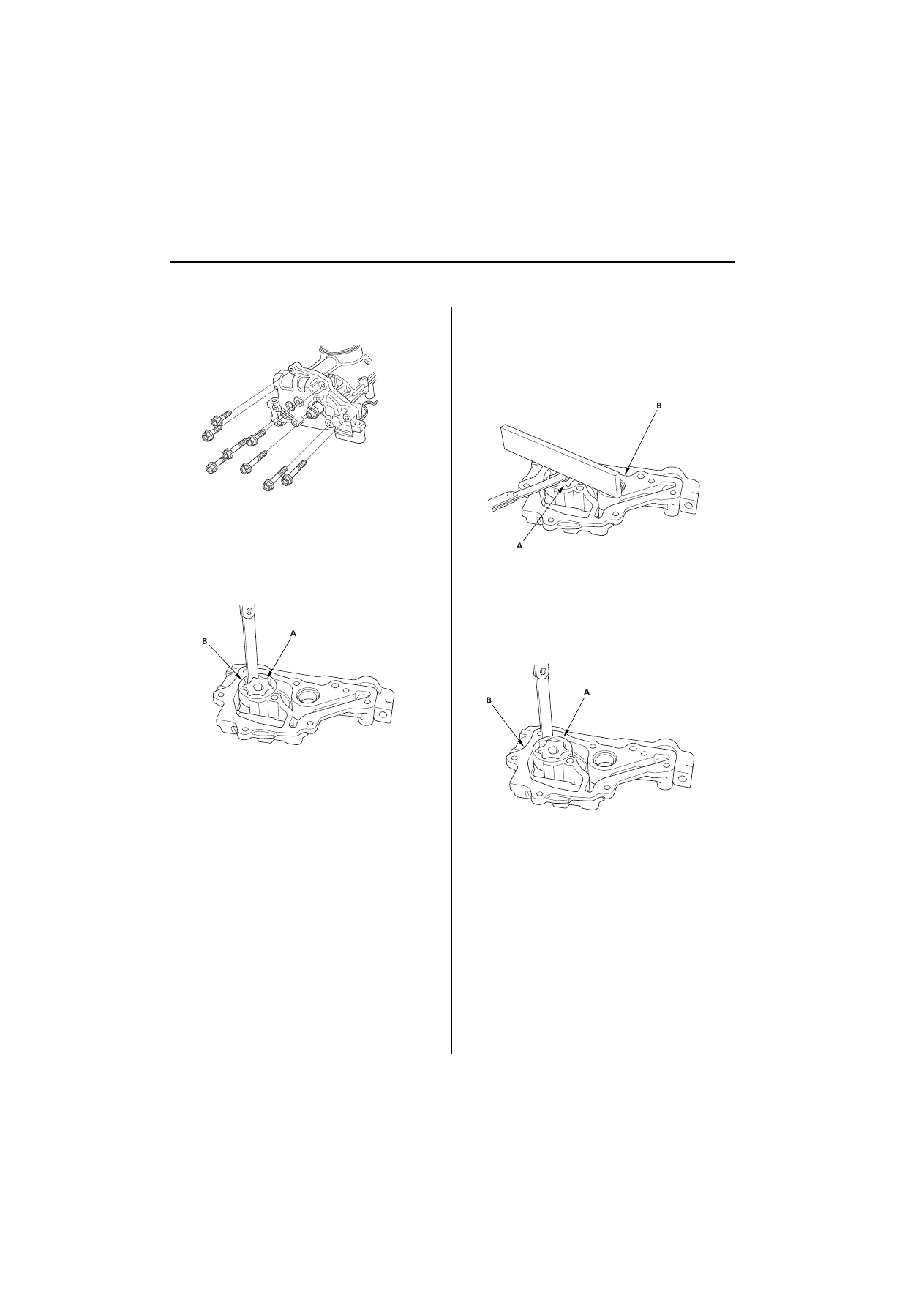
Apply engine oil to the threads of the 8 mm bolts
(A).
Install the upper balancer shaft holder (B) and
baffle plate (C).
(cont’d)
(QJLQH0HFKDQLFDO
(QJLQH/XEULFDWLRQ
2LO3XPS2YHUKDXOFRQW¶G
Install the pump housing.
2LO3XPS,QVWDOODWLRQ
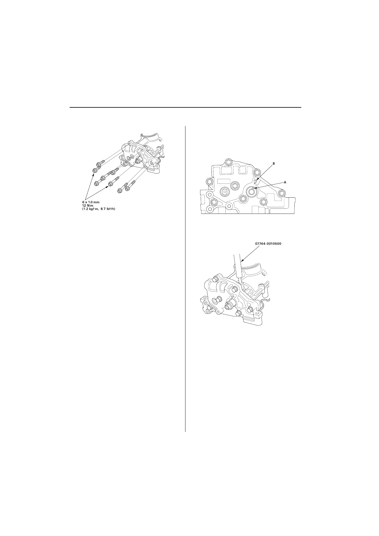
Check the No. 1 piston at TDC (see step 1 on
Align the dowel pin (A) on the rear balancer shaft
with the mark (B) on the oil pump.
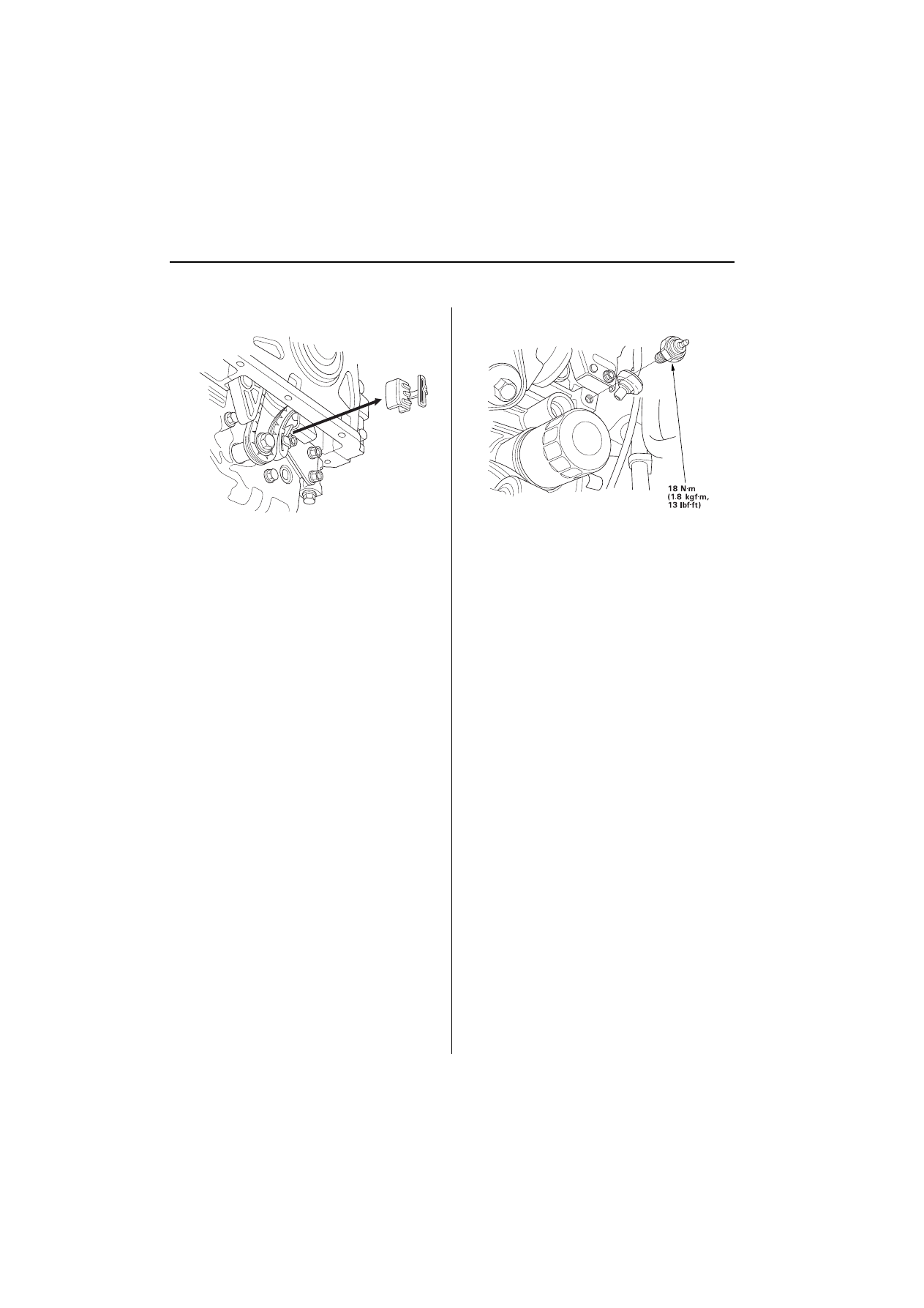
To hold the rear balancer shaft, insert a pin driver
into the hole in the rear balancer shaft, through the
maintenance hole on the lower balancer shaft
holder.
(QJLQH/XEULFDWLRQ
Apply engine oil to the threads of the oil pump
sprocket mounting bolt (A).
Loosely install the oil pump (B), then install the oil
pump sprocket (C).
Remove the pin driver (D).
Tighten the oil pump mounting bolts.
Squeeze the new oil pump chain tensioner (A),
then install the set clip (B) on it as shown.
NOTE: The set clip is supplied with the oil pump chain
tensioner.
Install the oil pump chain tensioner.
(cont’d)
(QJLQH0HFKDQLFDO
(QJLQH/XEULFDWLRQ
2LO3XPS2YHUKDXOFRQW¶G
Remove the set clip from the oil pump chain
tensioner.
Install the oil pan
2LO3UHVVXUH6ZLWFK5HSODFHPHQW
Disconnect the oil pressure switch connector, then
remove the oil pressure switch.
Apply liquid gasket to the oil pressure switch
threads, then install the oil pressure switch.
Wyszukiwarka
Podobne podstrony:
Automotive Engine Lubrication & Cooling Systems
Group 4 0 I6 Engine
Group 009 Engine Mounting
ENGINE LUBRICATION & COOLING SYSTEM
Group 2 5L4 I4 Engine
FP w 08
08 Elektrownie jądrowe obiegi
archkomp 08
02a URAZY CZASZKOWO MÓZGOWE OGÓLNIE 2008 11 08
ankieta 07 08
08 Kości cz Iid 7262 ppt
08 Stany nieustalone w obwodach RLCid 7512 ppt
2009 04 08 POZ 06id 26791 ppt
08 BIOCHEMIA mechanizmy adaptac mikroor ANG 2id 7389 ppt
depresja 08 09
W15 08 II
więcej podobnych podstron