C102960-0 Page 1 of 14
02.04.2008
© The information contained in this document is the sole property of Steerprop Ltd. any reproduction or disclosure in part or whole without written permission is prohibited.
DOC-1017-1
Steerprop Seal
System
Service Manual
Revision history:
REV. DATE MODIFIER DESCRIPTION
0 2.4.2008
AaNi Created
A
B
C
D
E
F

C102960-0 Page 2 of 14
02.04.2008
© The information contained in this document is the sole property of Steerprop Ltd. any reproduction or disclosure in part or whole without written permission is prohibited.
DOC-1017-1
1
AZIMUTHING SEALS.......................................................................................................................... 3
2
PROPELLER SHAFT SEALS .............................................................................................................. 3
2.1
S
EAL SYSTEM
................................................................................................................................... 4
2.2
S
TART
-
UP
......................................................................................................................................... 4
2.3
S
EAL LUBRICATION
.......................................................................................................................... 5
2.4
S
EAL SERVICE
................................................................................................................................... 5
2.5
S
EAL OIL TANK
................................................................................................................................. 6
2.5.1
Seal oil tank ................................................................................................................................. 6
2.5.2
Seal oil tank filling using lubrication pump................................................................................. 7
2.6
S
EAL OIL LEVEL MONITORING
.......................................................................................................... 8
2.6.1
Seal oil tank level switch SL04 .................................................................................................... 8
2.6.2
Seal oil tank level alarm test........................................................................................................ 8
2.7
S
EAL OIL PRESSURE ADJUSTING VALVE
(M
ANUAL
D
RAÍN
) ............................................................. 9
2.7.1
Pressurized air............................................................................................................................. 9
2.7.2
Seal oil tank pressure switch ......................................................................................................13
2.7.3
Seal oil tank air pressure low alarm test ....................................................................................13
2.8
F
AULT FINDING
...............................................................................................................................14
C102960-0 Page 3 of 14
02.04.2008
© The information contained in this document is the sole property of Steerprop Ltd. any reproduction or disclosure in part or whole without written permission is prohibited.
DOC-1017-1
1 A
ZIMUTHING
S
EALS
The number of the azimuth tube seals is
three in series.
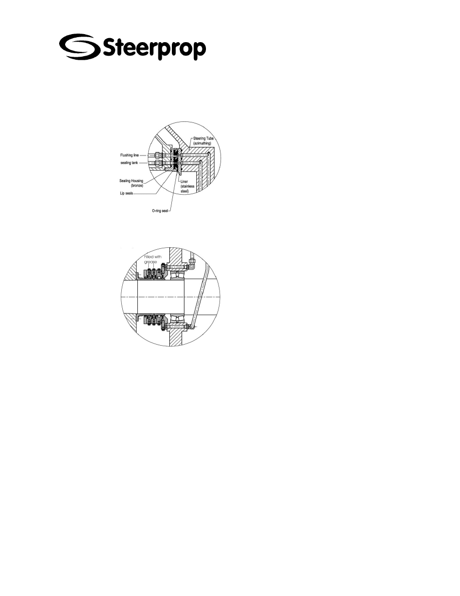
2 P
ROPELLER SHAFT SEALS
The propeller shaft seal has a separate
lubrication system equipped with a
separate seal oil tank.
The rope guard with line cutters are
furnished. The liner on the shaft is
made of special hardened chrome steel
alloy.
The propeller seal is a radial seal that
has a blocking chamber. The blocking
chamber witch is situated between the
second and third seal from aft, is
connected via piping to a separate seal
oil tank.
There are also block mounted anodes
to be replaced by overhaul.
C102960-0 Page 4 of 14
02.04.2008
© The information contained in this document is the sole property of Steerprop Ltd. any reproduction or disclosure in part or whole without written permission is prohibited.
DOC-1017-1
2.1 S
EAL SYSTEM
The propeller shaft seal
asembly consists of four seal
elements in sequence. The
rope guard with line cutters
are furnished. The liner on the
shaft is made of special
hardened chrome steel alloy.
The propeller seal is a
quadruple radial seal that has
a blocking chamber. The
blocking chamber witch is
situated between the third and
fourth seal from aft, is
connected via piping to a
separate seal oil tank.
For the seal to operate
correctly it is important that the
pressure inside the blocking
chamber is according to
instructions. To make sure of
this, before launching, it has to
be made sure that the
pressure chamber is filled with
oil, the piping leading to the
tank has been bleeding and
the tank is filled with oil.
The seal condition is to be
monitored regularly by
checking the oil level at seal
oil tank. The seal oil tank has
also low level monitoring.
The lubrication of the seal
wears a little amount of oil
constantly. Therefore a little oil
consumption belongs to the
normal seal lubrication. The
daily consumption is ca. 1% of
the oil amount in the seal
chamber.
2.2 S
TART
-
UP
For the seal to operate correctly it is important that the pressure inside the blocking
chamber is according to instructions. To make sure of this, before launching, it has to
be made sure that the pressure chamber is filled with oil, the piping leading to the tank
has been bleeding and the tank is filled with oil.

C102960-0 Page 5 of 14
02.04.2008
© The information contained in this document is the sole property of Steerprop Ltd. any reproduction or disclosure in part or whole without written permission is prohibited.
DOC-1017-1
2.3 S
EAL LUBRICATION
The oil consumption of rotary seals depends on the size of the seal, the peripheral
velocity of the lubrication oil at the prevailing temperature and the condition of the
sealing surfaces of the lip seals and the bush.
The seal condition is to be monitored regularly by checking the oil level at seal oil tank.
The seal oil tank has also low level monitoring.
The lubrication of the seal wears a little amount of oil constantly. Therefore a little oil
consumption belongs to the normal seal lubrication up to 15 cc/h.
2.4 S
EAL SERVICE
b
R
EMOVING THE SPACER RING
Removal of the spacer ring, which is notched at two places, enables the aft seal to be
moved in the direction of the stern tube. Thus, in the event of excessive wear on the
bush, the lip seals can be moved to a new unworn running surface. This area,
however, must be free of imperfections if accelerated wear of the lip seals is to be
avoided. lt is therefore vital to carefully inspect the bush in advance. The spacer ring
can be removed by fracturing it at the two notches, an operation usually carried out
with a hammer and chisel. The chisel blade must not be wider than the spacer ring,
and the point must f it into the notch. After the removal of one of the gaskets, the seal
must again be attached to the stern tube; if the second gasket should become
damaged, this, too, must be removed. A replacement gasket must be cut through using
a dovetail shaped cut and have jointing compound applied to it. After fitting, the bolts
must be locked with chrome steel wire.
b
G
ENERAL
Before fitting the propeller shaft and the propeller seal ensure that the propeller shaft,
the bearings, and the stern tube are clean and free of damage. Lubrication lines for the
seals should also be checked for being leak-free and internally clean. In addition, the
tolerances and the tapped holes which are relevant for fitting should be checked.
These tolerances are given on the assembly drawings. The bushes, which are fitted
with mounting supports, must not be withdrawn from the housing to prevent damage to
both the bushes and the lip seals. To protect the chrome steel bush of the aft seal from
corrosion due to sea water it is recommended that the anodes are clean and in good
condition. At all times the seals must be protected against grinding dust and /or welding
spatters.
b
F
ITTING THE SEAL
The aft seal should always be slid onto the propeller shaft as a unit with the bush,
spacer ring and both gaskets, after which the supplied retaining bolts should be used to
bolt it to the housing, forming an oil tight seal. When fitting a lubricated aft seal ensure
that the gaskets and the spacer ring are fitted in the correct position. For a fixed pitch
propeller fit the static seal (compression ring and 0-ring and I or a gasket) before fitting
the propeller. Once fitted, bolt the bush flange to the propeller using the retaining bolts.
The retaining bolts are locked together with chrome steel wire. After fitting, check that
the distance between the stern tube and the propeller hub or protective cover agrees
with that given.
C102960-0 Page 6 of 14
02.04.2008
© The information contained in this document is the sole property of Steerprop Ltd. any reproduction or disclosure in part or whole without written permission is prohibited.
DOC-1017-1
2.5 S
EAL OIL TANK
*
BEFORE OIL FILLING OR LEVEL CHECKING:
*
CLOSE VALVE SV10
*
BLOW-OUT AIR PRESSURE USING VALVE PV21
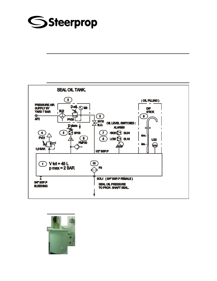
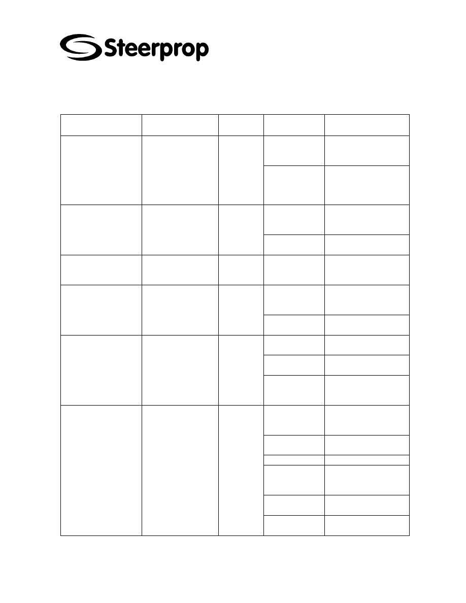
2.5.1 S
EAL OIL TANK
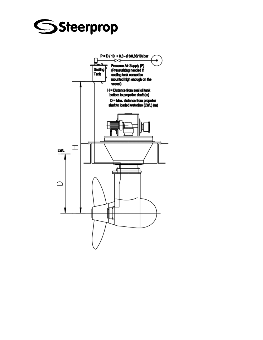
The system consists of a special pressurized head tank with low and
high level and pressure alarm for monitoring steering tube and propeller
shaft seal condition.
The seal oil tank is situated above the waterline and air pressure is
adjusted so that the oil pressure in the blocking chamber is 0.3 bar
higher than the water pressure outside the seal and the oil pressure
inside the propulsion unit.
C102960-0 Page 7 of 14
02.04.2008
© The information contained in this document is the sole property of Steerprop Ltd. any reproduction or disclosure in part or whole without written permission is prohibited.
DOC-1017-1
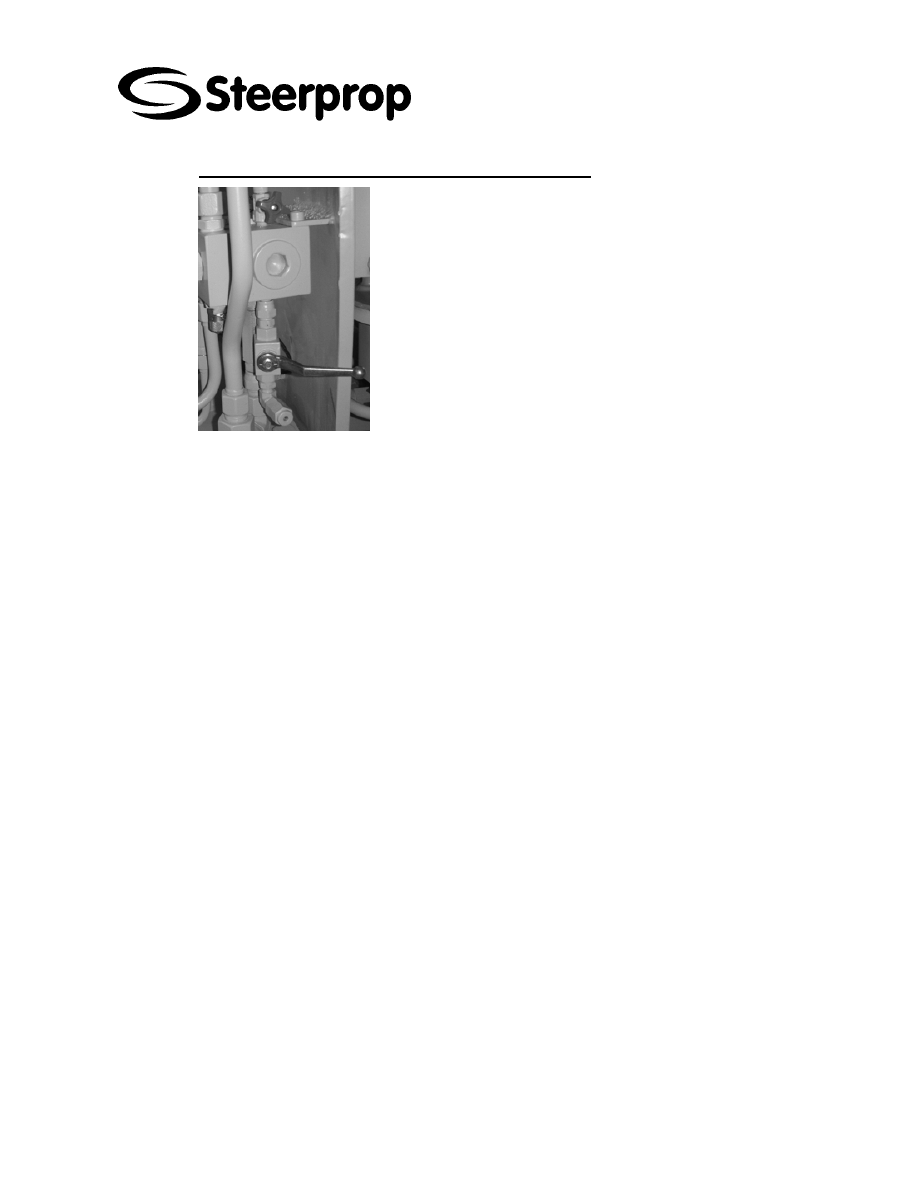
2.5.2 S
EAL OIL TANK FILLING USING LUBRICATION PUMP
Below the lubrication oil block at propulsor is seal oil tank filling
valve.
The valve is shown at normal operation position ”closed”.
When you fill the seal oil tank,
1. close the valve SV10
2. blow out the pressure using valve PV21
3. check the oil level with the dip stick
4. fill or add carefully to seal oil tank to the max pos
at dip stick using the filling valve
5. close the filling valve
6. check the oil level with the dip stick
7. open the valve SV10
Check the oil level at propulsor. Add also oil to there if needed.
C102960-0 Page 8 of 14
02.04.2008
© The information contained in this document is the sole property of Steerprop Ltd. any reproduction or disclosure in part or whole without written permission is prohibited.
DOC-1017-1
2.6 S
EAL OIL LEVEL MONITORING
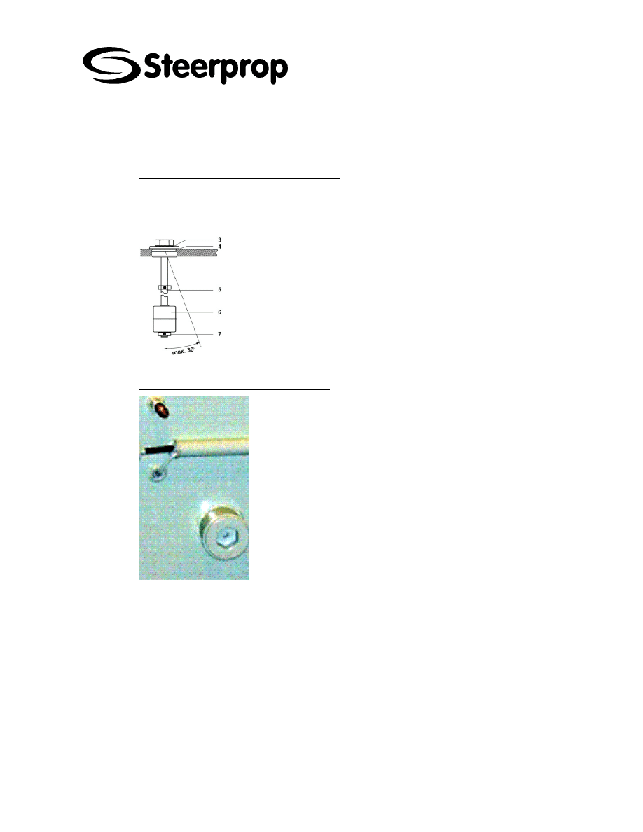
2.6.1 S
EAL OIL TANK LEVEL SWITCH
SL04
The level switch is installed in the seal oil tank. The switch has two floats, one is
monitoring the low level of the oil and second high level of the seal oil.
OIL LEVEL SWITCH
Switch has 0.5 A contact
Mounting position as in drawing
2.6.2 S
EAL OIL TANK LEVEL ALARM TEST
Open the dip stick with 32 mm hex wrench.
Thread the test tool carefully through the hole.
Pull the upper float carefully up (do not break the float and its
fastening by pulling it hard).
Seal oil level alarm will appear.
Release the float
Seal oil level alarm will disappear.
Push the lower float carefully down (do not break the float and its
fastening by pushing it hard).
Seal oil level alarm will appear.
Release the float.
Seal oil level alarm will disappear.
Pull the test tool carefully out
Close the test plug with 32 mm hex wrench

C102960-0 Page 9 of 14
02.04.2008
© The information contained in this document is the sole property of Steerprop Ltd. any reproduction or disclosure in part or whole without written permission is prohibited.
DOC-1017-1
2.7 S
EAL OIL PRESSURE ADJUSTING VALVE
(M
ANUAL
D
RAÍN
)
2.7.1 P
RESSURIZED AIR
Pressure air supply to seal oil tank panel......................................max 10 bar
In the panel the seal oil system pressure is adjusted depending on tank
installation height.
2.7.1.1 INSTALLATION
Refer to WARNINGS and CAUTIONS prior to installation.
Install as close to the point of use as possible.
Unit must be installed with the flow in the direction of the flow arrow on the
body cover and with bowl down.
Avoid using reducing bushings, couplings, etc., whenever possible to install
this product. These devices restrict air flow and can affect performance.
Install filter/regulator in a vertical position with bowl side down.
Maximum pressure rating is 150 psig (10.3 bar) for transparent plastic
bowls, and 250 psig (17.2 bar) for metal bowls. Temperature range is 32°F
to 125°F (0°C to 52°C) for transparent plastic bowls, and 32°F to 150°F
(0°C to 65.5°C) for metal bowls.
This product is supplied with two auxiliary ports located on the front and
rear faces of the body. These ports may be used as additional
filtered/regulated ports or for pressure gauges. A pipe plug is supplied to
block the unused port. Make sure pipe plug is sealed before installation.
To increase regulated pressure, pull adjusting knob up and turn clockwise.
To reduce pressure, turn knob counterclockwise. To lock knob, push down.
To panel mount this unit the following applies: Panel clearance hole
diameter = 1.94" (49.3 mm).
To install a drain line, use the following procedure:
On units with the MANUAL DRAIN, attach flexible tubing having an I.D. of
3/16" (4.8 mm) to drain stem.
C102960-0 Page 10 of 14
02.04.2008
© The information contained in this document is the sole property of Steerprop Ltd. any reproduction or disclosure in part or whole without written permission is prohibited.
DOC-1017-1
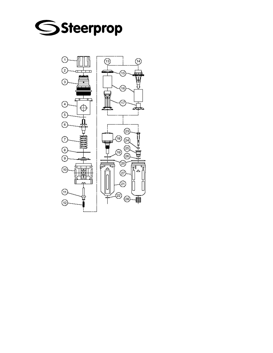
NNR = Not Normally Replaced
Knob
Panel nut
Bonnet (NNR)
Body cover (NNR)
Thrust washer (NNR)
Adjusting screw assembly (NNR)
Main spring
Slip ring
Diapragm assembly
Body assembly (NNR)
Valve assembly
Valve spring
“Old” design
“New” design
Deflector
5 micron element
Retainer
Automatic float drain
Auto drain O-ring
Bowl O-ring
Metal bowl with sigth gauge
Drain steam
Drain steam O-ring
Drain steam O-ring
Drain seat
Drain seat O-ring
Plastic bowl / bowl guard
Drain knob
C102960-0 Page 11 of 14
02.04.2008
© The information contained in this document is the sole property of Steerprop Ltd. any reproduction or disclosure in part or whole without written permission is prohibited.
DOC-1017-1
2.7.1.2 MAINTENANCE
*
DEPRESSURIZE SYSTEM BEFORE ATTEMPTING SERVICE!THIS UNIT MAY BE
SERVICED WITHOUT REMOVING THE UNIT FROM THE COMPRESSED AIR LINE UNIT
SHOULD BE SERVICED AT LEAST EVERY SIX MONTHS.
If you are unsure of which regulator you have, contact your local Wilkerson distributor
or call Wilkerson.
b
1.
F
ILTER ELEMENT REPLACEMENT
:
DePReSSURIze both upstream and downstream pressure.
Remove bowl / bowl guard assembly by pushing up on bowl assembly and
turning counterclockwise (viewed from below). Clean inside of bowl using a
clean, dry cloth. Inspect plastic bowl for damage and replace if necessary.
Remove filter element by turning retainer counterclockwise.
Remove old element and discard.
Install a new filter element and reassemble in reverse order. See table side
for torque values.
b
2.
V
ALVE ASSEMBLY
:
Depressurize both upstream and downstream pressure.
Remove bowl / bowl guard assembly and element retainer assembly as
outlined in maintenance Step #1.
Remove the valve spring and valve assembly, if not already done.
Inspect all seals and components for damage and replace as required.
Clean seals and components with mild detergent and water (No Solvents!).
Use a clean, dry cloth to wipe any contamination from the valve seat inside
the body.
Lubricate valve stem and lower valve O-ring seal with a light coat of
lubricant.
Reassemble in reverse order. See table on reverse side for torque values.
b
3.
M
AIN
S
PRING AND
D
IAPHRAGM
:
Depressurize unit, both upstream and downstream.
Turn adjusting knob counterclockwise to remove all spring force, then
remove bonnet by turning counterclockwise.
Remove adjusting screw assembly, main spring, slip ring and diaphragm
assembly.
Inspect diaphragm and the relief seat, on relieving models, for damage or
contamination. Replace diaphragm assembly if necessary. Clean relief seat
with a soft, dry cloth. Reassemble in the reverse order making sure slip ring
is properly positioned on top of the diaphragm. Bonnet torque values are
shown in the table below.
b
4.
L
EVEL
Liquid level in the bowl must be kept below the level indicator line as
marked. It is recommended practice to drain a unit equipped with the
manual drain at least once during an eight (8) hour period. To do so, rotate
the drain knob to the left one or two turns.*
C102960-0 Page 12 of 14
02.04.2008
© The information contained in this document is the sole property of Steerprop Ltd. any reproduction or disclosure in part or whole without written permission is prohibited.
DOC-1017-1
b
5.
O
PERATION
Before returning unit to service, insure that all seals have been properly
reinstalled or replaced and components requiring torque have been
properly tightened. Also, insure that bowl seal O-ring and bowl have been
installed properly and that the bowl is in the locked position and the drain is
properly secured.
*
*NOTE: IN THE EVENT THE DRAIN KNOB IS OVER-ROTATED, IT MAY BECOME
DISENGAGED FROM THE DRAIN STEM. IN SUCH A CASE, PULL DOWN ON BOTH THE
KNOB AND THE STEM WHILE ROTATING CLOCKWISE TO RE-ENGAGE. (VIEWED
FROM BELOW.)
2.7.1.3 TROUBLESHOOTING
LEAKS
If regulated pressure begins to creep, an uncontrolled rise in regulated
pressure, it will most likely be caused by contamination on the valve seat.
Refer to Maintenance Step #2, Valve Assembly to remedy the condition.
If the unit leaks from the vent holes in the bonnet, it may be caused by
contamination on the diaphragm relief seat, seal deterioration of relief seat
or diaphragm damage. Refer to Steps #2 and #3 under maintenance to
remedy the condition. Replace all damaged or worn components.
C102960-0 Page 13 of 14
02.04.2008
© The information contained in this document is the sole property of Steerprop Ltd. any reproduction or disclosure in part or whole without written permission is prohibited.
DOC-1017-1
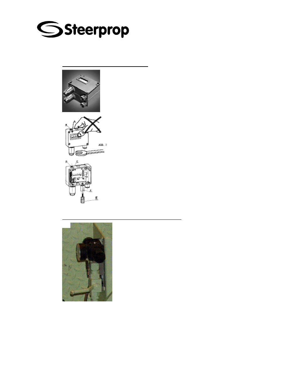
2.7.2 S
EAL OIL TANK PRESSURE SWITCH
Pressure monitoring switch
the switch has adjustment inside of the cover
there is indicator pointer showing the adjusted alarm limit
When mounting the pressure switch do not counterhold the torque of
the wrench by holding the case (Abb. 1).
The dial accuracy is ±2% of the range. Every unit is individually calibrated, so
a manometer verification is not necessary.
Type with invariable differential
1. Loosen lock screw (A)
2. Adjust upper switching point with range spindle (B) The Lower witching
point results from the fixed switch differential
3. Tighten lock screw (A)
2.7.3 S
EAL OIL TANK AIR PRESSURE LOW ALARM TEST
.
Close the air valve.
Release the pressure by pulling the ring at relief valve.
Seal oil pressure alarm will appear.
Open the air valve.
Alarm will disappear
C102960-0 Page 14 of 14
02.04.2008
© The information contained in this document is the sole property of Steerprop Ltd. any reproduction or disclosure in part or whole without written permission is prohibited.
DOC-1017-1
2.8 F
AULT FINDING
FAULT EFFECT
TEMPORARY
ACTION
CAUSE REMEDY
Oil leak in the
tank, piping or
somewhere else
Add oil after finding out
the reason for lack of oil
and repairing faults.
Seal oil level is
lowering continuously,
when the shaft is not
rotating
Low oil consumption
up to 1 % of the seal
size (l/d) is not an
indication for a fault in
the seal. The seal
needs a little oil for
lubrication.
Tank height or
pressure is not
right
Check the seal tank
height and pressure and
adjust, if needed.
Tank height or
pressure is not
right
Check the seal tank
height and pressure and
adjust, if needed
Seal oil level is
lowering continuously,
when the shaft is
rotating
Malfunction in
the seal system
Check the seal condition
and repair it
Seal oil level is rising
continuously, when the
shaft is not rotating
Tank height or
pressure is not
right
Check the seal tank
height and pressure and
adjust, if needed
Tank height or
pressure is not
right
Check the seal tank
height and pressure and
adjust, if needed
Seal oil level is rising
continuously, when the
shaft is rotating
Malfunction in
the seal system.
Check the seal condition
and repair it
Water in seal oil Change the oil or
separate water from oil.
Malfunction in
the seal system
Repair the seal system
Water in seal oil
circulation
The oil color can be
grey.
Tank height or
pressure is not
right
Check the seal tank
height and pressure and
adjust, if needed
There are not
enough
pressurized air
Check and repair air
supply
Air leakage in
the circuit
Check and repair the
tightness of the system
Air filter clogged Replace filter
Regulating valve
does not work
properly
Adjust or repair the
regulating valve
Relief valve
malfunction
Adjust or repair the relief
valve
Seal tank pressure low
The shut-off
valve is closed
Open valve.
Wyszukiwarka
Podobne podstrony:
C102968 0 SERVICE LOCAL STEERING
C102964 0 SERVICE VOLTAGE SUPPLY
C102965 0 SERVICE CONTROL UNIT
C102962 A SERVICE TRANSMITTER UNIT
C102961 A SERVICE STEERING GEAR
System nawigacyjny BMW Service Mode
C102990 0 SERVICE SYSTEM STARTING NO REMOTE
general cooling system servicing
Gas systems after market services
System Services for Ad Hoc Routing Architecture, Implementation and68030
ac system general servicing
Czy instalować Dodatek Service Pack 2 dla systemu Windows XP
więcej podobnych podstron