C102961-A Page 1 of 32
20.08.2008
© The information contained in this document is the sole property of Steerprop Ltd. any reproduction or disclosure in part or whole without written permission is prohibited.
DOC-1017-1
Steerprop Electric
Steering Gear
Service Manual
Revision history:
REV. DATE MODIFIER DESCRIPTION
0 2.4.2008
AaNi Created
A
B
C
D
E
F

C102961-A Page 2 of 32
20.08.2008
© The information contained in this document is the sole property of Steerprop Ltd. any reproduction or disclosure in part or whole without written permission is prohibited.
DOC-1017-1
1
STEERING GEAR SYSTEM ................................................................................................................ 4
2
SLEWING RING / TURNING GEAR ................................................................................................. 4
3
ELECTRIC DRIVEN STEERING GEAR ........................................................................................... 5
3.1
L
OW STEERING SPEED TEST
.............................................................................................................. 5
4
STEERING GEAR ................................................................................................................................. 6
4.1
INSTALLATION: ........................................................................................................................... 6
4.1.1
General instructions .................................................................................................................... 6
4.1.2
Installation instructions for flange mounted gear unit ................................................................ 6
4.2
A
CCESSORY INSTALLATION INSTRUCTIONS
..................................................................................... 7
4.2.1
Motor Assembly: .......................................................................................................................... 7
4.2.2
Motor shaft adapter ..................................................................................................................... 7
4.2.3
Accessory Assembly: .................................................................................................................... 7
4.3
MAINTENANCE: ........................................................................................................................... 7
4.3.1
Routine maintenance: .................................................................................................................. 7
5
ELECTRIC MOTOR ............................................................................................................................. 8
5.1
M
ANUAL TURNING
........................................................................................................................... 8
5.2
F
AN
................................................................................................................................................... 8
6
DISC BRAKE .......................................................................................................................................... 9
6.1.1
Operation description .................................................................................................................. 9
6.1.2
Manual release (disengaging) ..................................................................................................... 9
6.1.3
Operation ..................................................................................................................................... 9
6.2
B
RAKE ASSEMBLY
.......................................................................................................................... 11
6.3
M
ANUAL LEVER ASSEMBLY
........................................................................................................... 12
6.4
D
ISMANTLING
................................................................................................................................ 12
6.5
V
OLTAGE SUPPLY
........................................................................................................................... 12
6.6
B
RAKE SERVICE
.............................................................................................................................. 13
6.7
S
PARE PARTS
.................................................................................................................................. 13
6.8
B
RAKE CONTROL MODULE
............................................................................................................. 14
6.9
B
RAKE CONTROL TEST
................................................................................................................... 14
7
FEEDBACK-TRANSMITTER (BR03) .............................................................................................. 15
8
FEEDBACK CABLE ........................................................................................................................... 16
8.1
B
LACK CABLE WITH NUMBERED CONNECTORS
E000678 .............................................................. 16
8.2
B
LACK CABLE WITH
A
LPHABET CONNECTORS
E000331 ............................................................... 17
8.3
Y
ELLOW CABLE WITH NUMBERED CONNECTORS
E000202 ............................................................ 17
8.4
O
RIGINAL YELLOW CABLE WITH NUMBERED CONNECTORS FOR DELIVERIES
W0004,7,9,10
E000202 ...................................................................................................................................................... 18
9
ELECTRIC STEERING UNIT ESU (INVERTER, FREQUENCY CONVERTER) .................... 19
9.1
O
PERATION AT MAIN CONTROL
...................................................................................................... 19
9.2
O
PERATION AT REMOTE BACK
-
UP CONTROL
.................................................................................. 19
9.3
O
PERATION AT LOCAL CONTROL
.................................................................................................... 19
10
BRAKE RESISTOR (BRU) ................................................................................................................. 20
11
MOTOR CONTROL UNIT (SMU) .................................................................................................... 21
11.1
E
MERGENCY OPERATION
................................................................................................................ 21
12
ELECTRIC STEERING GEAR ALARMS TEST PROCEDURE .................................................. 22

C102961-A Page 3 of 32
20.08.2008
© The information contained in this document is the sole property of Steerprop Ltd. any reproduction or disclosure in part or whole without written permission is prohibited.
DOC-1017-1
12.1
B
RAKE CONTROL VOLTAGE SUPPLY
............................................................................................... 22
12.2
S
TEERING MOTOR
1
FAN
................................................................................................................. 23
12.3
S
TEERING MOTOR
2
FAN
................................................................................................................. 23
12.4
E
LECTRIC STEERING GEAR
1
FAILURE TEST
................................................................................... 24
12.5
E
LECTRIC STEERING GEAR
2
FAILURE TEST
................................................................................... 24
12.6
E
LECTRIC STEERING GEAR
1
WARNING TEST
................................................................................. 24
12.7
E
LECTRIC STEERING GEAR
2
WARNING TEST
................................................................................. 24
12.8
N
EW SYSTEMS FROM
6/2008 .......................................................................................................... 24
13
FAULT FINDING ................................................................................................................................ 25
13.1
G
ENERAL
........................................................................................................................................ 25
13.2
L
OW STEERING SPEED
.................................................................................................................... 27
13.3
P
LANETARY GEAR
.......................................................................................................................... 28
13.4
B
ASIC MOTOR
................................................................................................................................. 29
13.5
F
AN
................................................................................................................................................. 29
13.6
M
OTOR
B
RAKE
............................................................................................................................... 30
13.7
B
RAKE RESISTOR
(BRU) ................................................................................................................ 31
13.8
M
OTOR CONTROL UNIT
(SMU) ...................................................................................................... 31
14
STEERING MOTOR SPARE PARTS ............................................................................................... 32

C102961-A Page 4 of 32
20.08.2008
© The information contained in this document is the sole property of Steerprop Ltd. any reproduction or disclosure in part or whole without written permission is prohibited.
DOC-1017-1
1 S
TEERING GEAR SYSTEM
The steering gear consists of two electric steering motors connected via planetary
gears to the slewing ring. The steering gear is able to turn the propulsor continuously
360 degrees.
At emergency situation it is also possible to use only one steering gear, but the vessel
speed should be reduced.
Steering gears are also connected to propulsors lubrication system.
2 S
LEWING RING
/
T
URNING GEAR
The lubrication system belongs to lubrication before.

C102961-A Page 5 of 32
20.08.2008
© The information contained in this document is the sole property of Steerprop Ltd. any reproduction or disclosure in part or whole without written permission is prohibited.
DOC-1017-1
3 E
LECTRIC
D
RIVEN
S
TEERING
G
EAR
Electric driven steering gear has following main modules:
Electric motor MTxx
Feedback incremental encoder BR03
Feedback cable
Electric steering unit ESUxx (inverter, frequency converter)
Brake resistor BRUxx
Motor control unit SMUx
3.1 L
OW STEERING SPEED TEST
Select Remote, at SCU cabinet, with control with SC01
Switch OFF the power supply for steering drives ESUx1 and ESUx2 at
vessel’s circuit breaker panel (switchboard)
Turn the lever at wheelhouse
Alarm “low steering speed” appears
See alarm at SED (service display at SCU cabinet or ECP panel): (alarm as
expected)
Switch ON the supply for steering drives ESU1 and ESU2 from vessel’s
switchboard.
At wheelhouse control, turn steering lever to position other than current
Propulsor start to follow lever
Alarm disappears
C102961-A Page 6 of 32
20.08.2008
© The information contained in this document is the sole property of Steerprop Ltd. any reproduction or disclosure in part or whole without written permission is prohibited.
DOC-1017-1
4 S
TEERING GEAR
4.1 INSTALLATION:
4.1.1 G
ENERAL INSTRUCTIONS
¾
INSTALL THE PRODUCT CAREFULLY FOLLOWING THE
STEPS LISTED BELOW:
When installing the Gear unit, make sure the oil pipes are
correct position and tight.
If the gear unit is supplied in the multi-disk brake
configuration, make sure that the brake oil, breather, level
and drain plugs are in the correct position. Their position will
vary according to the assembly position.
The brakes in general must be correctly connected to their
specific control circuit.
This steering gear assembly is provided with mounting
flange for connecting the motors to the gear unit.
Note: Because the steering gear is connected to the main
lubrication circuit it is not necessary to fill it with oil prior to
installation.
4.1.2 I
NSTALLATION INSTRUCTIONS FOR FLANGE MOUNTED GEAR UNIT
Follow instructions at assembly drawing provided by Steerprop
They must be attached to a clean support surface that is perpendicular to
the drive axis. The “steering gear” must be assembled to the housing
assuring that the mating faces are clean and oil free.
The spigots and the coupling surfaces of the gear unit must be clean
without any dents. The checks described above are particularly important
ensure perfect alignment between the driven shaft and the output shaft of
the gear unit.
Lubricate all the spigots of the gear unit and the housing seat with grease
or oil or anaerobic sealant depending of construction.
After having inserted the gear unit into its housing and having placed it in
the correct position, then tighten the attachment bolts (specified in
assembly drawing), applying torque as indicated in the assembly drawing,
making sure that such torque settings are compatible with the other parts
(nuts and / or structure). The final assembly is secured with Loctite 638.

C102961-A Page 7 of 32
20.08.2008
© The information contained in this document is the sole property of Steerprop Ltd. any reproduction or disclosure in part or whole without written permission is prohibited.
DOC-1017-1
4.2 A
CCESSORY INSTALLATION INSTRUCTIONS
4.2.1 M
OTOR
A
SSEMBLY
:
Follow instructions at assembly drawing
4.2.2 M
OTOR SHAFT ADAPTER
The adapter is fastened to the motor shaft key joint using Loctite 638.
While assembling the motor to the gear unit, the coupling must be
lubricated with a thin layer of grease.
4.2.3 A
CCESSORY
A
SSEMBLY
:
To mount pinions, pulleys or couplings, use suitable equipment avoid seizing. As an
alternative, heat the piece to 80°-100° C. Lubricate the grooves with a thin layer of
grease or a no-grip lubricant and tighten attachment bolts applying the torque indicated
in the table "torque setting ".
4.3 MAINTENANCE:
ATTENTION: All maintenance activities must be carried out under safety conditions.
4.3.1 R
OUTINE MAINTENANCE
:
The operator is responsible for routine maintenance and must carry out the following
activities.
After a brief operating period of about 100 hours (breaking-in), check that
there are no metallic parts with unusual dimension in the magnetic plug of
the gear unit and in any multi-disk brake.
C102961-A Page 8 of 32
20.08.2008
© The information contained in this document is the sole property of Steerprop Ltd. any reproduction or disclosure in part or whole without written permission is prohibited.
DOC-1017-1
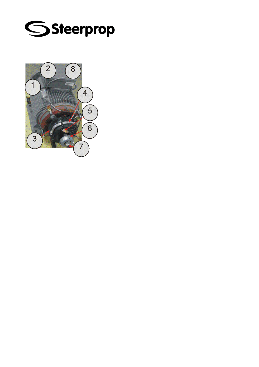
5 E
LECTRIC MOTOR
1 Basic motor
2 Motor connection box
3 Disc Brake
4 Disc Brake Manual lever
5 Disc Brake monitoring (optional item, not used)
6 Feedback transmitter (see page 15)
7 Rotation nut (manual turning device)
The electric motor consists of following modules:
Motor
Disc brake
Feedback-transmitter
Fan
The electric motor gives the steering torque to the steering gear, which turns the
propulsor via slewing ring.
The electric motor has two shaft ends the one is connected to steering gear and the
one has feedback transmitter and disc brake (one motor).
The electric motor has thermistors for the temperature monitoring. The thermistor is
monitored by the frequency converter ESU. The ESU is connected to the vessel’s
alarm system and alerts operator when motor temperature is high.
5.1 M
ANUAL TURNING
The motor shaft non-drive-end has a provision for manual turning.
5.2 F
AN
The motor non-drive end has an external cooling fan. The cooling fan has a separate
voltage supply from brake and fan control unit. The fan is only running when the ESU is
in run mode. The fans will stop when ESU goes to stand-by mode.

C102961-A Page 9 of 32
20.08.2008
© The information contained in this document is the sole property of Steerprop Ltd. any reproduction or disclosure in part or whole without written permission is prohibited.
DOC-1017-1
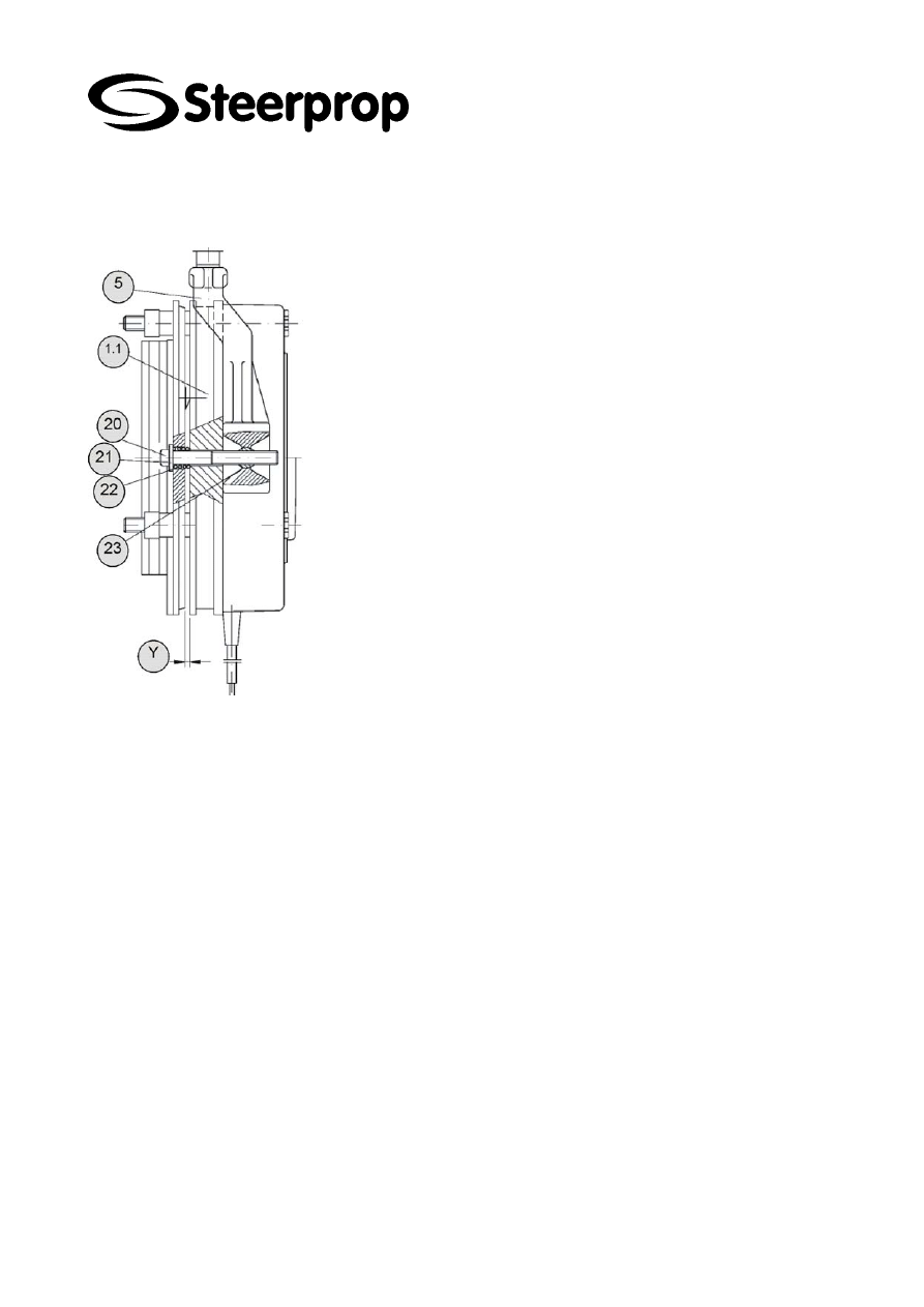
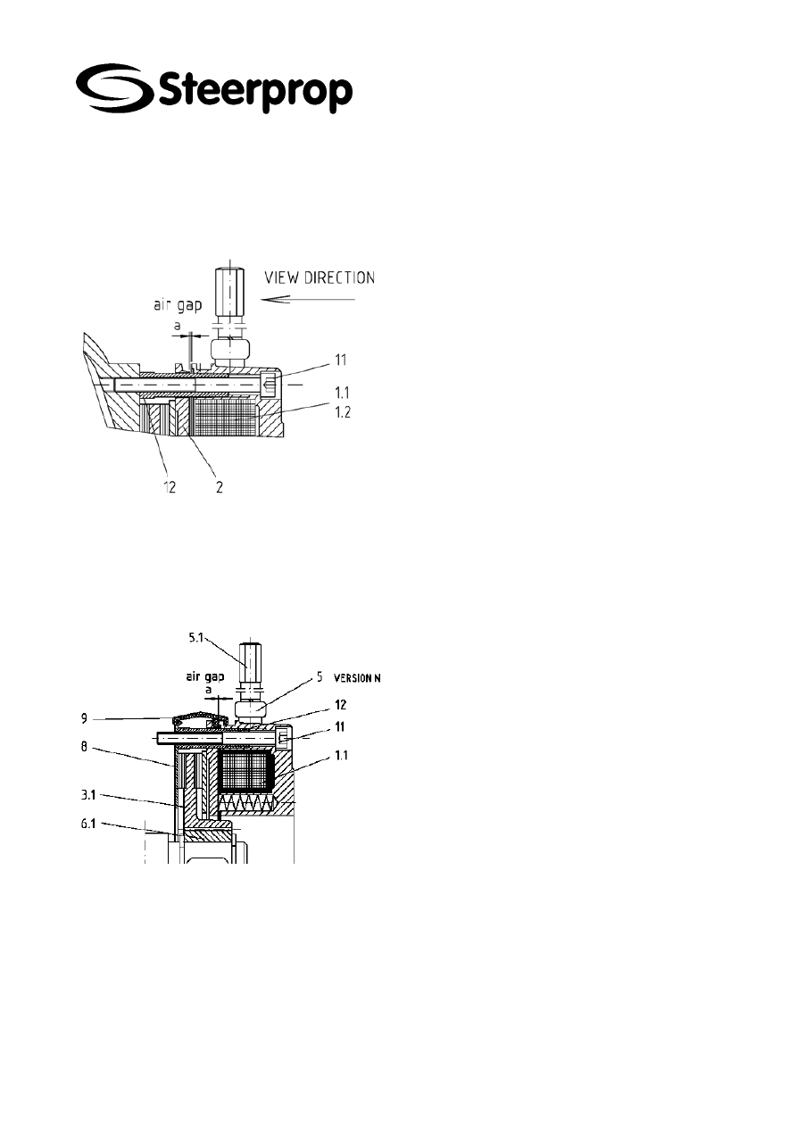
6 D
ISC BRAKE
The brake motor is equipped with disc brake to keep the propulsor angle at black-out
situations.
The disc brake is also stopping device at over-speed situations. When ESU senses
over-speed via feedback encoder brake is applied.
Disc brake
Manual release device
Brake control module at motor connection box
6.1.1 O
PERATION DESCRIPTION
The ventilated electromagnetic spring-loaded brake is a fail-safe brake with two friction
surfaces because it is engaged in it’s de-energized.
The braking moment is produced by springs pressing the anchor plate against the
rotor, when brake is de-energized.
The fitted pressure springs (pos. 4) press the axially moveable anchor plate (pos. 2)
onto the rotor which is connected flush to the shaft and which in turn presses onto the
flange (pos 7.), friction plate (pos. 8) or motor flange.
The braking action is produced as follows:
A magnetic force is generated by applying a DC voltage to the excitation winding in the
magnet body (pos. 1.1) and this force pulls the anchor plate (pos. 2) onto the magnet
body (pos. 1.1). The brake rotor (pos. 3.1) is released and the brake is ventilated.
The standard version of the spring-loaded brake is supplied with permanently adjusted
braking moment Mbn. On all brake sizes this moment is produced by springs (pos. 4).
6.1.2 M
ANUAL RELEASE
(
DISENGAGING
)
The disc brake is equipped with manual disengage. The brake has hand release lever,
which you can use to disengage the brake at service situation and at emergency
operation.
The brake features a manual release assembly (pos. 5) enabling it to be ventilated
mechanically in the case of a loss of power for example.
Pressing the manual release lever (pos. 5) causes the anchor plate (pos. 2) to be
pulled onto the magnet assembly. This produces an air gap between the rotor (pos.
3.1) and anchor plate (pos. 2) and the brake is ventilated.
!
The adjustment of the manual release must not be tampered with for reasons of
safety.
6.1.3 O
PERATION
Applying a DC voltage to the excitation winding in the magnet body (pos. 1) induces a
magnetic force which pulls on the anchor plate. This plate is pulled across the air gap
"a" towards the magnet body (pos. 1) against the force of the springs (pos. 4).
The braking rotor (pos. 3) is released and the braking action is interrupted.

C102961-A Page 10 of 32
20.08.2008
© The information contained in this document is the sole property of Steerprop Ltd. any reproduction or disclosure in part or whole without written permission is prohibited.
DOC-1017-1
The inclusion of a manual ventilation assembly enables the brake to be mechanically
ventilated.
Pressing the manual ventilation lever (pos. 5) causes the anchor plate (pos. 2) to be
pulled onto the magnet assembly (pos. 1). This produces an air gap between the rotor
(pos. 3) and anchor plate (pos. 2) and the brake is ventilated.
C102961-A Page 11 of 32
20.08.2008
© The information contained in this document is the sole property of Steerprop Ltd. any reproduction or disclosure in part or whole without written permission is prohibited.
DOC-1017-1
6.2 B
RAKE ASSEMBLY
The brake linings and braking surfaces must be carefully protected against
foreign matter. Under no circumstances must they come in contact with oil and
grease. Even low contaminants of this kind can greatly reduce the braking
moment.
Before commencing work on an installed spring-loaded brake always disconnect
or switch off the motor-side power supply from the vessel’s switchboard.
Tightening torque M
A
= 25 Nm
The brake is supplied pre-assembled.
Circlip, (pos. 14) to be fitted into the slot on
the shaft.
Fitted key (pos 15) fitted in the motor shaft.
Push hub (pos. 6.1) on to the shaft.
Secure hub, (pos. 6.1) using circlip (pos.
16).
If applicable, mount friction plate (pos 8),
or flange (pos. 7).
Push rotor (pos. 3.1) on to the hub (pos.
6.1)
Secure magnet assembly with three fixing
screws, for tightening torque see table
3.2.2.
Set air gap "a" = 0.4 mm
Check the air gap "a" at three places on
the circumference; if necessary, undo the
cylinder bolts (pos. 11) and correct the
airway by turning the threaded collars
(pos. 12). After making the adjustment re
tighten the cylinder bolts and recheck the
air gap "a".
Mount the dust ring (pos. 9) if applicable.
Electrical connection.
*
ALL MAINTENANCE AND REPAIR WORK MUST BE MADE BY SPECIALIST
PERSONNEL AND WITH THE POWER TO THE SPRING-LOADED BRAKE SWITCHED
OFF.
C102961-A Page 12 of 32
20.08.2008
© The information contained in this document is the sole property of Steerprop Ltd. any reproduction or disclosure in part or whole without written permission is prohibited.
DOC-1017-1
6.3 M
ANUAL LEVER ASSEMBLY
Place the hand lever (pos. 5) on the magnet body
(pos 1.1 or 1.2) and push the two pins through.
Screw the cylinder bolt (pos. 20) with washer
(pos. 21)and spring (pos. 22) into the pins.
Note:
When screwing up the dimension "y = 1
mm" between the magnet housing
and the anchor plate must be kept uniform all
round (see table 3.2.2).
!
The adjustment of the manual ventilation must
not be altered at a later
date, even when the air gap "a" is readjusted.
6.4 D
ISMANTLING
Dismantling the spring-loaded brake and the manual ventilation is made in the reverse
order of the assembly.
6.5 V
OLTAGE SUPPLY
The electrical connection must only be made when the no power is connected.
The operating voltage (DC) of the brake is indicated on the magnet housing.
C102961-A Page 13 of 32
20.08.2008
© The information contained in this document is the sole property of Steerprop Ltd. any reproduction or disclosure in part or whole without written permission is prohibited.
DOC-1017-1
6.6 B
RAKE SERVICE
Spring-loaded brakes are virtually maintenance-free.
The air gap "a" and thus the rotor wear must be checked at certain intervals and be
adjusted, if necessary, or the rotor replaced.
RESETTING THE BRAKING CLEARANCE
When looking in the direction of the arrow (see fig.)
the three fixing bolts (pos. 11) are to be undone by
half a turn.
The threaded collars (pos. 12) which surround the
fixing bolts (pos. 11) can then be screwed into the
magnet body (pos. 1) by turning anticlockwise.
Turning the 3 fixing bolts (pos. 11) clockwise allows
the magnet body (pos. 1) to be moved towards the
anchor plate until the nominal air gap is reached, as
measured using a feeler gauge.
The 3 threaded collars are then also screwed
clockwise out of the magnet body until they but up.
Finally, the fixing bolts (pos. 11) are retorqued.
The air gap must then be rechecked.
6.7 S
PARE PARTS
The brake code number (at the magnet body) should be always inform when ordering
spare parts
Magnet assembly (1.1)
Rotor cpl (3.1)
Springs (4)
Manual vent assy. Complete (5)
Manual lever (6)
Hub for rotor (6.1)
Flange (7)
Friction plate (8)
Dust ring (9)
Fixing bolt (11)
Hollow screws (12)
O-ring (13)
C102961-A Page 14 of 32
20.08.2008
© The information contained in this document is the sole property of Steerprop Ltd. any reproduction or disclosure in part or whole without written permission is prohibited.
DOC-1017-1
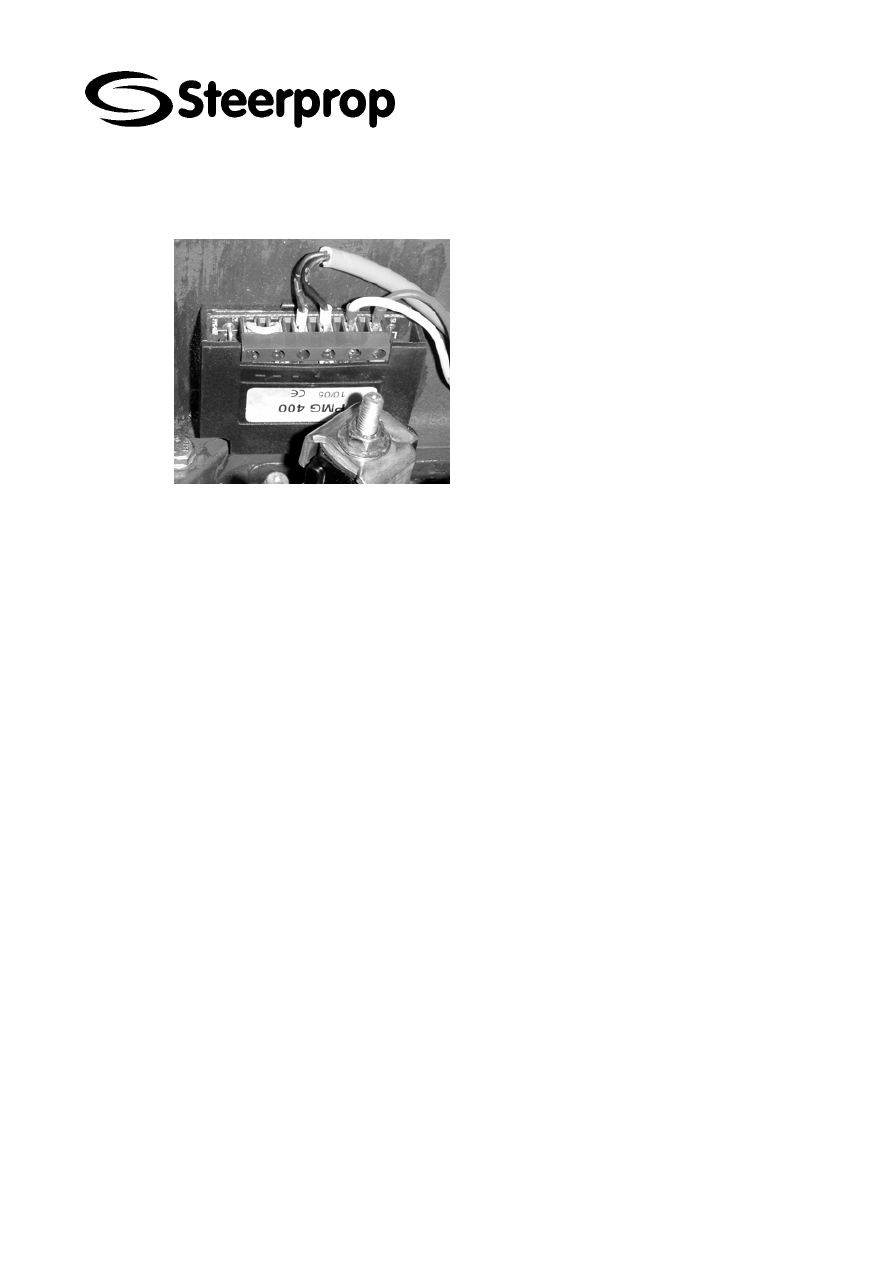
6.8 B
RAKE CONTROL MODULE
The brake control module is installed into motor
connection box. The control module will transform
the steering gear AC supply voltage to the brake
control DC voltage. The brake action is not
depending of the direction of the DC-voltage.
6.9 B
RAKE CONTROL TEST
Select remote control with SC01 located on SCU cabinet.
Turn the switches at FB1 and FB2, located in SMU cabinet, to 0
The alarm “low steering speed” will appear.
See that alarm appears on SED (service display at SCU or ECP)
Turn the switches at FB1 and FB2, located in SMU cabinet, to 1
The low steering speed or wrong direction alarm will disappear.
Check, that steering gear brakes are keeping the propulsor in this position
The system is ready for remote control
C102961-A Page 15 of 32
20.08.2008
© The information contained in this document is the sole property of Steerprop Ltd. any reproduction or disclosure in part or whole without written permission is prohibited.
DOC-1017-1
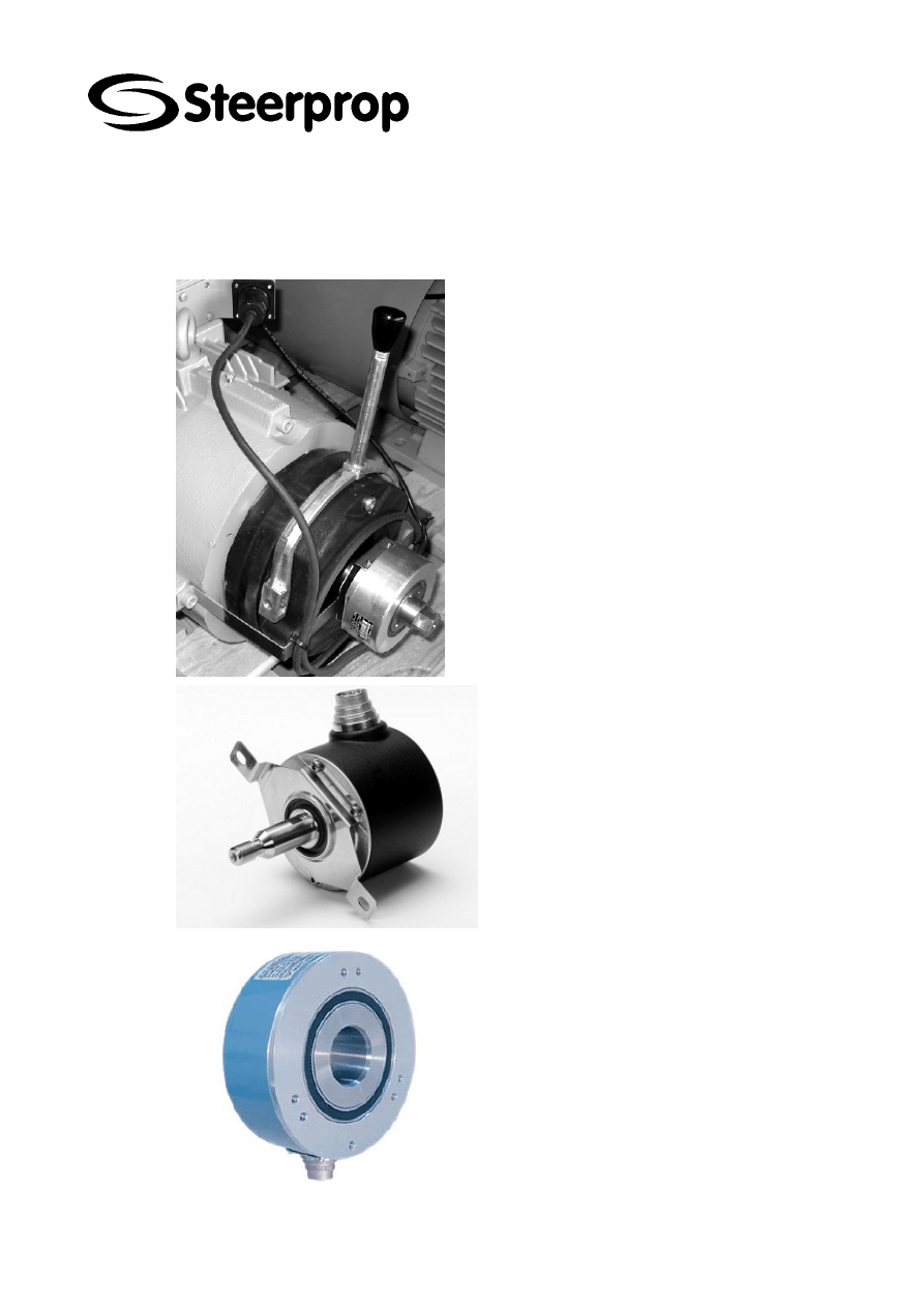
7 F
EEDBACK
-
TRANSMITTER
(BR03)
For steering motor shaft speed and shaft angle
measurement is at motor shaft end a increment
transmitter.
Black cable with numerically labeled connector.
Feedback transmitter code E000727.
Black cable with alphabet labeled connector. The
transmitter colour can be also aluminium.
Feedback transmitter code E000459.
Yellow or black cable with numerically labeled
connector. Feedback transmitter code E000174
C102961-A Page 16 of 32
20.08.2008
© The information contained in this document is the sole property of Steerprop Ltd. any reproduction or disclosure in part or whole without written permission is prohibited.
DOC-1017-1
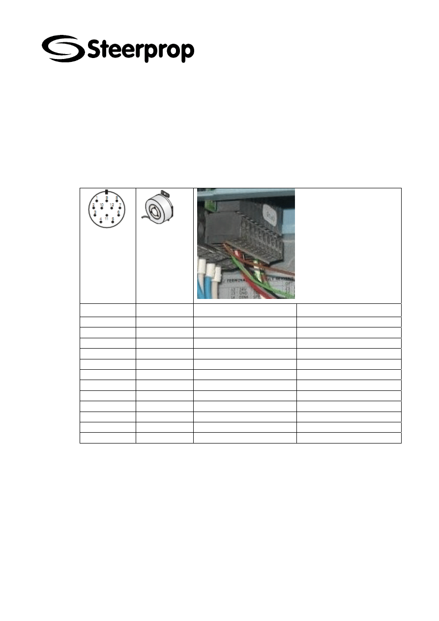
8 F
EEDBACK CABLE
Feedback cable is between feedback transmitter at motor and Electric Steering Unit.
For the good working feedback system this cable should be installed with a continuous
cable (no connections between) from motor to ESU.
If the cable is broken, it should be changed, not repaired.
8.1 B
LACK CABLE WITH NUMBERED CONNECTORS
E000678
NUMBER WIRE
SIGNAL
FREQUENCY
CONVERTER
1 pink
B
inv
A5:4
2 blue
3 red
N
A5:5
4 black
N
inv
A5:6
5 brown
A
A5:1
6 green
A
inv
A5:2
7 violet
8 grey
B
A5:3
9 not
connected
10 white/green
negative
A5:9
11 white
warning
12 brown/green
positive
A5:10
C102961-A Page 17 of 32
20.08.2008
© The information contained in this document is the sole property of Steerprop Ltd. any reproduction or disclosure in part or whole without written permission is prohibited.
DOC-1017-1
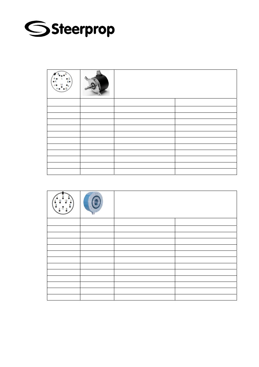
8.2 B
LACK CABLE WITH
A
LPHABET CONNECTORS
E000331
NUMBER WIRE
SIGNAL
FREQUENCY
CONVERTER
A pink
B
inv
A5.4
B blue
C red N
A5:5
D black
N
inv
A5:6
E brown
A
A5:1
F green
A
inv
A5:2
G violet
H grey
B
A5.3
M white/green
negative
A5:9
L white
warning
K brown/green
positive
A5:10
8.3 Y
ELLOW CABLE WITH NUMBERED CONNECTORS
E000202
NUMBER WIRE
SIGNAL
FREQUENCY
CONVERTER
1 green
B
inv
A5:4
2 not
connected
3 grey
N
A5:5
4 pink
N inv
A5:6
5 white
A
A5:1
6 brown
A
inv
A5:2
7 not
connected
8 yellow
B
A5:3
9 not
connected
10 blue Negative
A5:9
11 black
Early
warning
12 red Positive
A5:10
C102961-A Page 18 of 32
20.08.2008
© The information contained in this document is the sole property of Steerprop Ltd. any reproduction or disclosure in part or whole without written permission is prohibited.
DOC-1017-1
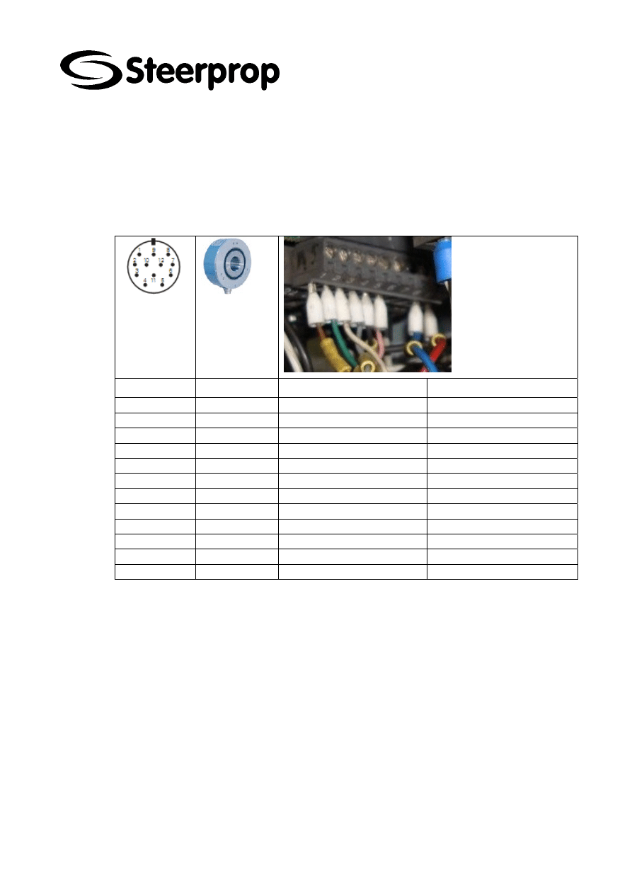
8.4 O
RIGINAL YELLOW CABLE WITH NUMBERED CONNECTORS FOR
DELIVERIES
W0004,7,9,10
E000202
Newer yellow replacement cable has different pin/colour combinations. It is
recommended to use the black numbered cable as replacement cable to avoid the
numbering problems.
NUMBER WIRE
SIGNAL
FREQUENCY
CONVERTER
1 grey
B
inv
A5:4
2 not
connected
3 black
N
A5:5
4 pink
N inv
A5:6
5 brown
A
A5:1
6 green
A
inv
A5:2
7 not
connected
8 white
B
A5:3
9 not
connected
10 blue Negative
A5:9
11 black
Early
warning
12 red Positive
A5:10

C102961-A Page 19 of 32
20.08.2008
© The information contained in this document is the sole property of Steerprop Ltd. any reproduction or disclosure in part or whole without written permission is prohibited.
DOC-1017-1
9 E
LECTRIC
S
TEERING
U
NIT
ESU
(
INVERTER
,
FREQUENCY
CONVERTER
)
The steering control is carried out with ESU. Using the basic inverter as hardware
Steerprop has developed a special software for propulsor steering control.
The ESU has a separate instruction.
9.1 O
PERATION AT MAIN CONTROL
The propulsor has two parallel Electric Driven Steering Gear systems. The steering
control is carried at Steerprop Control Unit, which gives speed and direction commands
to ESU.
If there is no direction commands, ESU will keep the steering angle.
9.2 O
PERATION AT REMOTE BACK
-
UP CONTROL
At remote back-up control the switch SC08 gives (wheelhouse) direction command to
the ESU. The steering speed is constant.
The steering speed is ca 50 % of the main control speed.
9.3 O
PERATION AT LOCAL CONTROL
At local control the switch SC02 gives (propulsor) direction command to the ESU. The
steering speed is constant.
The steering speed is ca 50 % of the main control speed.

C102961-A Page 20 of 32
20.08.2008
© The information contained in this document is the sole property of Steerprop Ltd. any reproduction or disclosure in part or whole without written permission is prohibited.
DOC-1017-1
10 B
RAKE RESISTOR
(BRU)
The brake resistor converts the braking energy produced by steering motors to heat.
The brake resistor is equipped with overheat warning, that is connected to ships alarm
as “steering gear warning”.

C102961-A Page 21 of 32
20.08.2008
© The information contained in this document is the sole property of Steerprop Ltd. any reproduction or disclosure in part or whole without written permission is prohibited.
DOC-1017-1
11 M
OTOR CONTROL UNIT
(SMU)
The propulsor is equipped with a motor control unit SMU. This unit takes care of the
control of the motor fans and disc brake of one propulsor and lubrication pump. The
fans are working parallel.
This unit has three power supplies and one AC voltage supply for main control
voltage. If you make service, you should switch off all supplies. This unit has also
circuit breakers for fan and disc brake circuits.
Through this unit can both ESU units control all the disc brakes of one propulsor. By
means of change over contacts, inside the SMU, both ESU units can operate the disc
brake in the event that one ESU is disconnected from it’s power supply.
11.1 E
MERGENCY OPERATION
If there is no malfunction with the steering motor or steering gear operation itself, you
can continue to operate with caution.
If circuit breaker FF1 and/or FF2, for steering fans, has tripped try to resetting it.
If circuit breaker FB1 and/or FB2, for steering brake, has tripped try to resetting it.
The following situations are acceptable to continue operation taking caution:
Steering motor fan(s) inoperable
o
The temperature of the motor will rise without cooling air flow. When
motor has reached unsafe operating temperature alarm will be displayed
on ESU.
The brake has hand release lever and you can lock it to disengaged
position.
C102961-A Page 22 of 32
20.08.2008
© The information contained in this document is the sole property of Steerprop Ltd. any reproduction or disclosure in part or whole without written permission is prohibited.
DOC-1017-1
12 E
LECTRIC STEERING GEAR ALARMS TEST PROCEDURE
This test will be started with a propulsor, which voltage supplies are on, then the
voltage supply switch SS01 is on and local control SC01 is switched to remote control
also electric supplies for pumps and steering gears are on.
This test should be started with the system in the following state:
All control voltage supplies on
Switch, at SCU, SS01 is on
Switch, at SCU, SC01 is switched to the REMOTE position
Both steering drives ESUx1 and ESUx2 power supplies are on
The vessel alarm and automation systems are running.
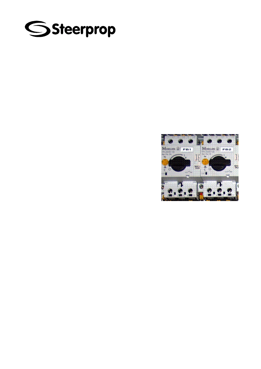
12.1 B
RAKE CONTROL VOLTAGE SUPPLY
Turn the switch at FB1 to 0
Contactors KB1 and KB3 will open
Contactors KB2 and KB4 will close
The voltage supply will transfer to FB2
SED (service display), at SCU or
ECP, indicates that “Circuit breakers
open”. To find, select STATUS from
main screen. Scroll though pages to
SMU functions page
Turn the switch at FB2 to 0
Contactor KB4 and KB4 will open
SED indicates “Circuit breakers open”
Steering brake drops down, if it has
been open. Steering brake will de-
energize and engage the friction rotor,
preventing the motor for spinning.
Turn the switch at FB1 to 1
Contactors KB1 and KB3 will close
The voltage supply will transfer back
to main supply of FB1
SED will indicate “Brake switch open”,
if ESU is in run mode
SED will indicate “Brake closed”, if
ESU is in stand-by mode
Turn the switch at FB2 to 1
SED indicates “Circuit breakers
closed”
C102961-A Page 23 of 32
20.08.2008
© The information contained in this document is the sole property of Steerprop Ltd. any reproduction or disclosure in part or whole without written permission is prohibited.
DOC-1017-1
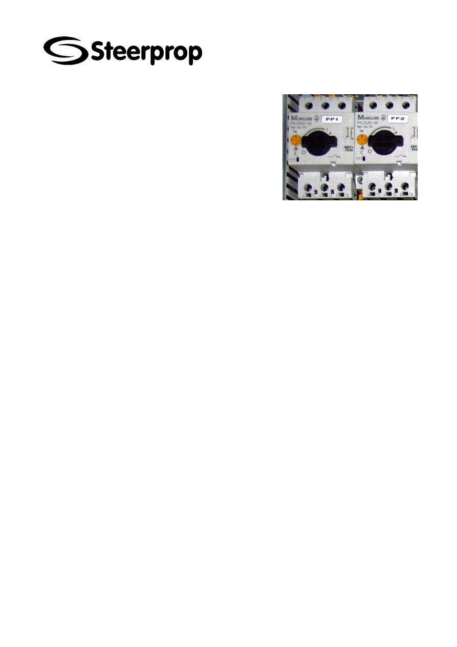
12.2 S
TEERING MOTOR
1
FAN
Turn the switch at FF1 to 0, circuit
breaker for fan open.
Fan at motor 1 will stop, if they are
running
SED indicates “Circuit breakers open”
Turn the switch at FF1 to 1, circuit
breaker for fan closed.
Fan at motor 1 will start
SED indicates “Circuit breakers
closed”
12.3 S
TEERING MOTOR
2
FAN
Turn the switch at FF2 to 0, circuit
breaker for fan open.
Fan at motor 2 will stop, if they are
running
SED indicates “Circuit breakers open”
Turn the switch at FF2 to 1, circuit
breaker for fan closed.
Fan at motor 2 will start
SED indicates “Circuit breakers
closed”

C102961-A Page 24 of 32
20.08.2008
© The information contained in this document is the sole property of Steerprop Ltd. any reproduction or disclosure in part or whole without written permission is prohibited.
DOC-1017-1
12.4 E
LECTRIC STEERING GEAR
1
FAILURE TEST
Switch OFF the supply for steering drives ESU1 from vessel’s switchboard.
The steering gear 1 failure will appear. The steering gear failure will appear
on vessel’s alarm system as well as on SED (service display) page for
steering drive status, at SCU or ECP.
Switch ON the supply for steering drive ESU1.
The alarm will disappear.
12.5 E
LECTRIC STEERING GEAR
2
FAILURE TEST
Switch OFF the supply for steering drives ESU2 from vessel’s switchboard.
The steering gear 2 failure will appear. The steering gear failure will appear
on vessel’s alarm system as well as on SED (service display) page for
steering drive status, at SCU or ECP.
Switch ON the supply for steering drive ESU2.
The alarm will disappear.
12.6 E
LECTRIC STEERING GEAR
1
WARNING TEST
Open the wire at terminal X1:T1 at SMU.
The warning will appear. The steering gear warning will appear on vessel’s
alarm system as well as on SED (service display) page for steering drive
status, at SCU or ECP.
Connect the wire at terminal X1:T1 at SMU.
The warning will disappear after ~20 s.
12.7 E
LECTRIC STEERING GEAR
2
WARNING TEST
Open the wire at terminal X2:T1 at SMU.
The warning will appear. The steering gear warning will appear on vessel’s
alarm system as well as on SED (service display) page for steering drive
status, at SCU or ECP.
Connect the wire at terminal X2:T1 at SMU.
The warning will disappear after ~20 s.
12.8 N
EW SYSTEMS FROM
6/2008
ESU unit has testing parameter. More details from Vacon’s new manual.

C102961-A Page 25 of 32
20.08.2008
© The information contained in this document is the sole property of Steerprop Ltd. any reproduction or disclosure in part or whole without written permission is prohibited.
DOC-1017-1
13 F
AULT FINDING
13.1 G
ENERAL
FAULT EFFECT
CAUSE
REMEDY
Steering motor
brake does not
”hold”
Propulsor turns freely,
when steering control
is not active
The brake does not keep the
propulsor position.
Repair the brake. Normal
operation situation the
steering function is active and
brake failure does not effect
operation.
Propulsor turns
slowly when
steering control is
not active.
See above
The brake does not keep the
propulsor position.
Repair the brake.
Propulsor turns
slowly all the time
in remote and
local control.
Steering speed of the
propulsor is greatly
reduced.
The steering motor feedback
transmitter BR03 is loose from
one motor shaft.
Repair or use only one
steering motor.
The steering motor feedback
transmitter is broken.
Repair or use only one
steering motor.
The steering motor feedback
transmitter BR03 cable is
broken or loose from one
motor.
Repair or use only one
steering motor.
Propulsor is not
turning smoothly.
Torque values of
the motors are
hunting.
Steering function
operates, but roughly
and perhaps violently
resulting in erratic
motor RPMs and
torque values.
The steering motor BR03
feed-back transmitters are
swapped to wrong motor. (i.e.
inboard ESU connected to
outboard motor)
Connected the right cable to
right motor.
Propulsor is
steering
continuously to a
certain point then
stopping and
steering back in
the other
direction.
It is not possible to
steer with propulsor.
Both steering motors are
connected with the wrong
phase.
Repair and check connection.
Propulsor is
turning first to one
way and then
another way
It is not possible to
steer with propulsor.
The steering commands from
SCU to ESU units are wrongly
connected.
Repair and check connection.
Propulsor is
overshooting in
steering
Should be careful.
The braking capacity is
lowered.
Check brake resistors and
ESU brake resistor function.

C102961-A Page 26 of 32
20.08.2008
© The information contained in this document is the sole property of Steerprop Ltd. any reproduction or disclosure in part or whole without written permission is prohibited.
DOC-1017-1
Propulsor is
continuously
rotating in one
direction.
It is not possible to
steer with propulsor.
The propulsor steering angle
transmitter gears are loose.
Repair and check.
Feedback transmitter RG10 is
broken.
Continuous
steering
operations.
Propulsor steering
has possible failure
There is possible planetary
gear failure.
Check the gear. And replace
the gear with new one.

C102961-A Page 27 of 32
20.08.2008
© The information contained in this document is the sole property of Steerprop Ltd. any reproduction or disclosure in part or whole without written permission is prohibited.
DOC-1017-1
13.2 L
OW STEERING SPEED
FAULT EFFECT
TEMPORARY
ACTION
CAUSE REMEDY
Low steering speed
The propulsor turns
slowly.
Wiring
or
connection
failure
Check and repair
External object
turns the
propulsor lower
part or prevents
to turn it
If the external object has
been the cause, you
should check, has the
propulsor other failures
due the object.
Propulsor
steering gear
has a failure.
See steering gear

C102961-A Page 28 of 32
20.08.2008
© The information contained in this document is the sole property of Steerprop Ltd. any reproduction or disclosure in part or whole without written permission is prohibited.
DOC-1017-1
13.3 P
LANETARY GEAR
FAULT EFFECT
CAUSE
REMEDY
Metallic parts with
unusual
dimension in the
magnetic plug
Stop this propulsor to
prevent further
damage until gear is
replaced. Use other
propulsor for steering.
The gear can be worn
Repair or replace gear
With steering
gear motor
running the gear
output shaft
doesn’t run
Incorrect
motor
assembly
Check coupling between gear
unit and motor.
Internal malfunction
Take contact to Steerprop
service
Oil leak from
seals
Damaged or worn seals
Take contact to Steerprop
service
Stiffening of seals due the
prolonged storage
Clean the area and check for
leakage again after a few days
Excessive noise
Internal malfunction
Take contact to Steerprop
service
Excessive
vibrations
Gear unit incorrectly installed
Check the connection and in-
line configuration
Coupling structure weak
Strengthen the structure
Internal malfunction
Take contact to Steerprop
service
Excessive
heating
No ventilation
Remove fairing
High thermal power
Insert oil circulation

C102961-A Page 29 of 32
20.08.2008
© The information contained in this document is the sole property of Steerprop Ltd. any reproduction or disclosure in part or whole without written permission is prohibited.
DOC-1017-1
13.4 B
ASIC MOTOR
FAULT EFFECT
CAUSE
REMEDY
Motor is not
running
No steering
Use only another
propulsor for steering.
Brake is engaged
See brake 6
The azimuth gear is jammed
Contact Steerprop service
Motor
temperature is
high
Steering power
limited.
Be careful and lower
the load
Brake is engaged and is
dragging
See brake 6. Lower ship
speed. The limitation is not
automatic.
The fan is not running
See fan 5.2
Phase is missing on supply to
motor resulting in higher
current draw. ESU will display
and signaling vessel’s alarm
system as well.
Check and repair the cabling,
wiring or connector
13.5 F
AN
FAULT EFFECT
CAUSE
REMEDY
Motor fan is not
running
Steering gear load
should be smaller,
motor load ability
smaller. Steering
motor will being to
rise in operating
temperature.
Lower steering load,
make steering with
another propulsor.
Voltage supply off
Steering gear load should be
smaller, motor load ability
smaller.
Lower steering load, make
steering with another
propulsor.
Find the reason and repair it
Circuit breakers open
Broken fan motor
Clogged fan

C102961-A Page 30 of 32
20.08.2008
© The information contained in this document is the sole property of Steerprop Ltd. any reproduction or disclosure in part or whole without written permission is prohibited.
DOC-1017-1
13.6 M
OTOR
B
RAKE
FAULT EFFECT
CAUSE
REMEDY
Brake not
disengaged,
motor brake does
not disengage
Propulsor does not
turn or turns slowly
The brake is dragging
and will “burn”
causing brake
assembly and motor
to overheat very
quickly potentially
damaging one or
both.
Air gap too large
Check air gap and adjust
Brake not receiving electrical
power
Check electrical connection
and control circuit
Voltage to brake coil too small Check connection voltage of
brake coil
The brake is blocked to
disengaged position
Remove mechanical blockage
Brake control voltage supply
off
Connect supply
Circuit breaker at SMU open
Connect circuit breaker
No command signal to brake
Check the control signals
between inverters and SCU,
brake is “on” as long as both
direction signals are off.
Fan problem, short circuit
No steering direction
command to steering inverters
When the direction signals are
“on”, the inverter takes care of
the position keeping.
Brake control module
malfunctioning.
Measure input and output of
module. Replace if necessary.
The brake has voltage supply
through the wrong circuit
connection or operation
Check other brake control
circuits
Check other inverter control
circuits
Check wiring or connection
and repair
Brake
disengaging
delayed
Air gap too large
Check air gap and adjust
Voltage to brake coil too small Check connection voltage of
brake coil
Brake not
activated, brake
is ”open”, brake
does not hold
The brake does not
keep the propulsor
position.
Voltage to coil too low
Check connection voltage of
brake windings
Brake is worn or wrong
adjusted
Adjust the brake or replace
friction surfaces or springs
Anchor plate mechanically
blocked
Remove mechanical blockage
Brake activation
delayed
Voltage to coil too low
Check connection voltage of
brake windings

C102961-A Page 31 of 32
20.08.2008
© The information contained in this document is the sole property of Steerprop Ltd. any reproduction or disclosure in part or whole without written permission is prohibited.
DOC-1017-1
13.7 B
RAKE RESISTOR
(BRU)
FAULT EFFECT
CAUSE
REMEDY
Slow braking
Steering braking
speed is a little lower.
Operate with care.
Brake resistor failure
Disconnect brake resistor from
ESU and measure ohmic
resistance at resistor
terminals. Correct value
should be labeled on resistor.
If low then resistor failing and
should be replaced.
Brake chopper failure at
inverter
See Vacon instructions
Resistor
overheating
Alarm “EXT fault” on
ESU keypad. Vessel’s
alarm system shows
steering warning.
Faulty brake resistor. DC-link
voltage of ESU too high.
Check ohmic resistance of
resistor. Investigate, why DC-
link voltage is high.
13.8 M
OTOR CONTROL UNIT
(SMU)
FAULT EFFECT
TEMPORARY
ACTION
CAUSE REMEDY
Circuit breaker open at
SMU unit
The SMU unit has
two separate
incoming power
supplies from
vessel’s switchboard.
The supply for
steering brake is
automatically
switched to the 2
nd
supply if the 1
st
is
disconnected, via
changeover contacts.
Therefore the
opening of one FB
circuit breaker does
not make any
influence to the
operation of the brake
control.
See 11.1
Short circuit at
brake
See brake
Short circuit at
fan
See fan
Cabling or wiring Find out the reason for
possible short circuit
and repair it.
The adjustment
of the circuit
breaker is
wrong.
Check the adjusting and
adjust according load.
High
temperature at
control unit
Lower temperature or
change circuit breakers
to bigger.

C102961-A Page 32 of 32
20.08.2008
© The information contained in this document is the sole property of Steerprop Ltd. any reproduction or disclosure in part or whole without written permission is prohibited.
DOC-1017-1
14 S
TEERING MOTOR SPARE PARTS
MOTOR
CODE
SPARE
MOTOR
CODE
BRAKE
RECTIFIER
DISC
BRAKE
BRAKE
HAND
LEVER
FAN FEEDBACK
ENCODER
20 M
FEEDBACK
CABLE
50 M
FEEDBACK
CABLE
001551 E000689 E000436 E000722 E000721 E000438 E000174 E000678 E000202
001552 E000690
E000438 E000174 E000678 E000202
E000305 E000693 E000736
E000733 E000459 E000343 E000331
E000306 E000694
E000733 E000459 E000343 E000331
E000313 E000689 E000736 E000446 E000716 E000442 E000459 E000343 E000331
E000314 E000690
E000442 E000459 E000343 E000331
E000345 E000689 E000736 E000446 E000716 E000442 E000459 E000343 E000331
E000522 E000689
E000442 E000459 E000343 E000331
E000603
E000736 E000686
E000687
1
E000741 E000678 E000202
E000603
E000736 E000686
S000220
2
E000741 E000678 E000202
E000689
E000736 E000732 E000731 E000442 E000727 E000678 E000202
E000690
E000442
E000727 E000678 E000202
E000693
E000736 E000732 E000735 E000733 E000727 E000678 E000202
E000694
E000733
E000727 E000678 E000202
E000826
E000736 X
X
X
E000727 E000678 E000202
E000827
X E000727
E000678
E000202
E000839
E000736 X
X
S000214 E000727 E000678 E000202
E000840
S000214
E000727 E000678 E000202
E000841
E000736 X
X
S000214 E000727 E000678 E000202
E000842
S000214
E000727 E000678 E000202
E000843
E000736 X
X
S000214 E000727 E000678 E000202
E000844
S000214
E000727 E000678 E000202
1
Supply 220 VAC, 50 Hz
2
Supply 220 VAC, 60 Hz
Wyszukiwarka
Podobne podstrony:
C102968 0 SERVICE LOCAL STEERING
C102964 0 SERVICE VOLTAGE SUPPLY
C102960 0 SERVICE SEAL SYSTEM
M36c Power Steering Gear
C102965 0 SERVICE CONTROL UNIT
M001860 B Eng Steering gear
PBO G 03 C03 Emergency response check list steering gear f
C102962 A SERVICE TRANSMITTER UNIT
M001863 B Eng Steering gear
62 STEERING GEAR POWER RACK & PINION
Pytania i odpowiedzi ? 17 Steering Gear
więcej podobnych podstron