DRY BRAKE SYSTEM
H8.00-12.00XM (H170-280HD) [F007, G007];
H13.00-16.00XM (H300-360HD) [E019, F019]
PART NO. 1494141
1800 SRM 937

SAFETY PRECAUTIONS
MAINTENANCE AND REPAIR
• When lifting parts or assemblies, make sure all slings, chains, or cables are correctly
fastened, and that the load being lifted is balanced. Make sure the crane, cables, and
chains have the capacity to support the weight of the load.
• Do not lift heavy parts by hand, use a lifting mechanism.
• Wear safety glasses.
• DISCONNECT THE BATTERY CONNECTOR before doing any maintenance or repair
on electric lift trucks. Disconnect the battery ground cable on internal combustion lift
trucks.
• Always use correct blocks to prevent the unit from rolling or falling. See HOW TO PUT
THE LIFT TRUCK ON BLOCKS in the Operating Manual or the Periodic Mainte-
nance section.
• Keep the unit clean and the working area clean and orderly.
• Use the correct tools for the job.
• Keep the tools clean and in good condition.
• Always use HYSTER APPROVED parts when making repairs. Replacement parts
must meet or exceed the specifications of the original equipment manufacturer.
• Make sure all nuts, bolts, snap rings, and other fastening devices are removed before
using force to remove parts.
• Always fasten a DO NOT OPERATE tag to the controls of the unit when making repairs,
or if the unit needs repairs.
• Be sure to follow the WARNING and CAUTION notes in the instructions.
• Gasoline, Liquid Petroleum Gas (LPG), Compressed Natural Gas (CNG), and Diesel fuel
are flammable. Be sure to follow the necessary safety precautions when handling these
fuels and when working on these fuel systems.
• Batteries generate flammable gas when they are being charged. Keep fire and sparks
away from the area. Make sure the area is well ventilated.
NOTE:
The following symbols and words indicate safety information in this
manual:
WARNING
Indicates a condition that can cause immediate death or injury!
CAUTION
Indicates a condition that can cause property damage!

Dry Brake System
Table of Contents
TABLE OF CONTENTS
General ...............................................................................................................................................................
Description .........................................................................................................................................................
Operation............................................................................................................................................................
Service Brakes ...............................................................................................................................................
Parking Brake................................................................................................................................................
Air Tank Repair .................................................................................................................................................
Relief Valve ....................................................................................................................................................
Drain Valve ....................................................................................................................................................
Brake Pedal Valve Repair..................................................................................................................................
Remove ...........................................................................................................................................................
Disassemble, Inspect, and Assemble ............................................................................................................
Install .............................................................................................................................................................
Air Chambers Repair .........................................................................................................................................
Remove ...........................................................................................................................................................
Disassemble ...................................................................................................................................................
Inspect ............................................................................................................................................................
Assemble ........................................................................................................................................................
Install .............................................................................................................................................................
Actuator Arms Repair........................................................................................................................................
Remove ...........................................................................................................................................................
Inspect ............................................................................................................................................................
Install .............................................................................................................................................................
Brake Assemblies Repair...................................................................................................................................
Brake Shoe, Remove ......................................................................................................................................
Camshaft, Remove.........................................................................................................................................
Clean ..............................................................................................................................................................
Inspect ............................................................................................................................................................
Camshaft, Install ...........................................................................................................................................
Brake Shoe, Install ........................................................................................................................................
Air Dryer ............................................................................................................................................................
Description .....................................................................................................................................................
Cartridge ........................................................................................................................................................
Remove.......................................................................................................................................................
Install .........................................................................................................................................................
Filter...............................................................................................................................................................
Remove.......................................................................................................................................................
Install .........................................................................................................................................................
Quick-Release Valve...........................................................................................................................................
Governor Check and Adjustment for Air Compressor .....................................................................................
Brake Shoes Adjustment ...................................................................................................................................
Specifications......................................................................................................................................................
Troubleshooting..................................................................................................................................................
This section is for the following models:
H8.00-12.00XM (H170-280HD) [F007, G007];
H13.00-16.00XM (H300-360HD) [E019, F019]
©2003 HYSTER COMPANY
i

"THE
QUALITY
KEEPERS"
HYSTER
APPROVED
PARTS
1800 SRM 937
Description
General
This section has the description and the service procedures for the parts of the brake system. The section
Perkins Diesel Engine 600 SRM 705 or 600 SRM 1068 has the service procedures for the air compressor.
Description
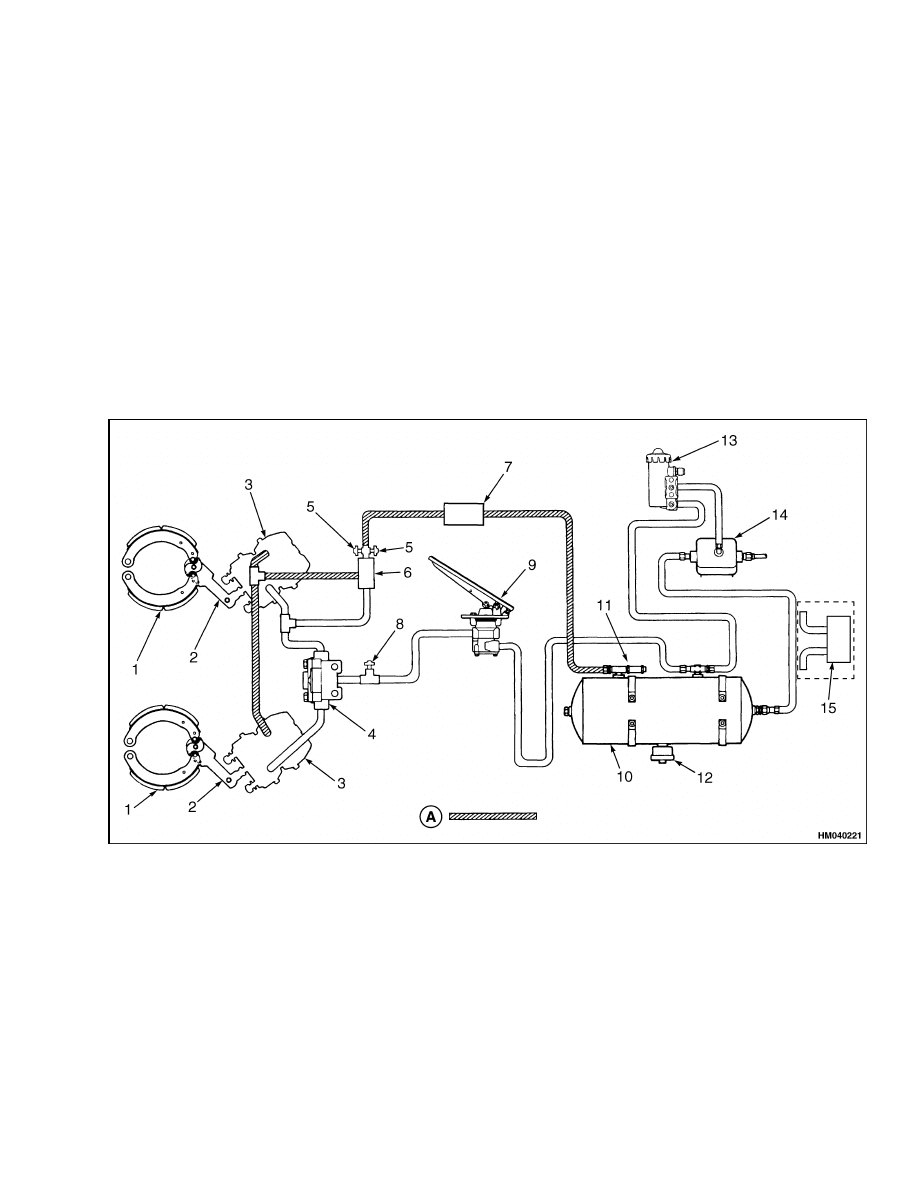
The brake system has two pedals, one pedal valve,
one air tank, and two brake assemblies. See Figure 1.
The pedal valve operates the service brakes and has
a linkage that disengages the transmission.
A friction disc brake assembly is installed behind the
planetary hub on each end of the drive axle. The
air tank is installed in the right-hand channel of the
frame. An air pressure gauge indicates the pressure
in the air tank. A pressure switch activates a warn-
ing light and an alarm on the instrument panel when
the air pressure is less than 483 kPa (70 psi). The air
tank has a relief valve to limit pressure in the system
and a drain valve to release water caused by conden-
sation. An air compressor on the engine keeps pres-
sure in the tank. A governor controls the pressure
developed by the compressor.
A. PARK CIRCUIT
1.
BRAKE ASSEMBLY
2.
ACTUATOR ARM
3.
AIR CHAMBER
4.
QUICK-RELEASE VALVE
5.
PARK BRAKE SWITCH (START ENGINE WITH
BRAKE "ON"; ENGAGE TRANSMISSION WITH
BRAKE "OFF")
6.
QUICK-RELEASE DOUBLE CHECK VALVE
7.
PARK BRAKE VALVE
8.
BRAKE LIGHT SWITCH (ONLY WITH LIGHTS)
9.
BRAKE PEDAL VALVE
10. AIR TANK
11. RELIEF VALVE
12. DRAIN VALVE
13. GOVERNOR
14. AIR COMPRESSOR
15. AIR DRYER (OPTIONAL)
Figure 1. Brake System Diagram
1

Operation
1800 SRM 937
Operation
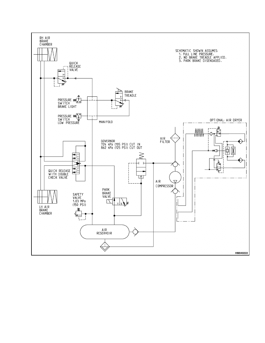
SERVICE BRAKES
The operation of the service brakes is controlled by
the brake pedal valve. See Figure 2 and Figure 5.
When the right-side (service brake) pedal is pushed,
the piston moves to the seat on the inlet valve. This
action closes the exhaust passage.
As the piston
moves farther, the inlet valve opens. Air from the
tank flows from the inlet port to the outlet port. The
air from the outlet port flows through a check valve
and a quick-release valve to the air chambers on the
drive axle. The pressure of the air moves a piston
assembly in each air chamber. The pistons actuate
the brake camshafts. The brake camshafts push the
brake shoes against the brake drums to apply the
service brakes.
The pressure of the air at the outlet port pushes the
piston in the brake pedal valve against the balance
spring. As the force of the brake air pressure becomes
equal to the force of the spring, the piston moves up
and the inlet valve closes. When the pedal is pushed
further, the greater force that is applied through the
spring gives higher air pressure at the air chambers.
This action applies the brakes with greater force.
The piston moves off the seat on the inlet valve when
the pedal is released. This action opens the exhaust
port and releases the air pressure. The sudden de-
crease in air pressure opens the exhaust port of the
quick-release valve. The brakes are released quickly
as a result. Return springs in the brake assemblies
pull the brake shoes away from the drums.
The left-side (inch/brake) pedal is mechanically
coupled with the right-side pedal and also operates
the service brakes. The inch/brake pedal also has a
linkage that is connected to the transmission control
valve. The linkage disengages the transmission as
the operator depresses the inch/brake pedal. The
transmission is in NEUTRAL when the inch/brake
pedal is fully depressed. The linkage engages the
transmission as the operator releases the inch/brake
pedal.
PARKING BRAKE
The parking brake system operates the service brake
assemblies. Large springs in the air chambers pro-
vide the energy to apply the brakes for parking. See
Table 1.
The operation of the parking brake system is initi-
ated by pulling out the red knob on the instrument
panel. This will electrically activate the park brake
valve. In normal operation, the knob on the valve is
pushed in (released). When the knob is pushed in, air
pressure from the tank compresses the large springs
in the park chambers of the brake air chambers. This
action releases the brakes. Constant air pressure is
necessary to keep the brakes released.
When the knob on the parking brake valve is pulled
out, the air pressure in the park chambers is released
through the parking brake valve. This action causes
the springs to apply the brakes for parking. The
springs automatically apply the brakes if the system
loses air pressure.
2
1800 SRM 937
Operation
Figure 2. Brake System Schematic
3
Operation
1800 SRM 937
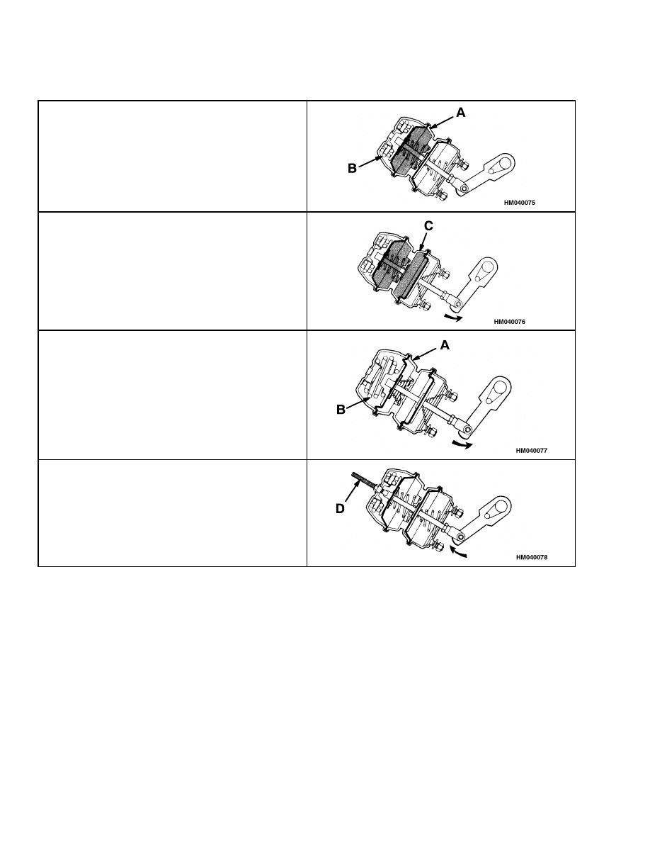
Table 1. Air Chambers Operation
BRAKES RELEASED. The knob on the parking
brake valve is pushed in. Air pressure enters
chamber A, compresses spring B, and releases
brakes. Air pressure keeps the power spring
compressed during operation of the truck.
SERVICE BRAKES APPLIED. The brake or
inch/brake pedal is pushed in. Air pressure enters
chamber C, pushes the diaphragm and piston, and
applies the brakes.
PARKING BRAKES APPLIED. The knob on the
parking brake valve is pulled out. Air pressure is
released from chamber A. Spring B pushes a rod and
the piston to apply the brakes.
BRAKES MANUALLY RELEASED. Release bolt
D is used to hold the power spring in the compressed
position. This procedure allows air chamber and
brake assembly repair or towing when the system
does not have air pressure.
4

1800 SRM 937
Air Tank Repair
Air Tank Repair
WARNING
Make sure that air pressure is released from air
tank before making repairs to air system. Pull
stem of relief valve to release air.
Do the following when you remove or install air tank:
1.
Clean area around fittings of tank.
2.
Release air pressure from air tank. Disconnect
all air lines at tank. Put caps on open lines.
3.
Remove bolts from brackets for tank. Slide tank
as necessary to remove top brackets from frame.
Remove tank.
4.
When installing air tank, connect air lines as
shown in Figure 1. Make sure that drain valve is
in lowest position. Start engine and check tank
and air lines for leaks.
RELIEF VALVE
1.
SPRING CAGE
2.
VALVE STEM
3.
SPRING
4.
CHECK BALL
5.
BODY
Figure 3. Relief Valve
The relief valve is installed in a tee fitting on the
tank. See Figure 3. The pressure setting of the re-
lief valve is 1034 kPa (150 psi). The pressure setting
cannot be adjusted. Replace relief valve if parts have
defects or damage.
DRAIN VALVE
Disassemble drain valve as necessary. See Figure 4.
Replace any damaged parts. Use water to clean di-
aphragm. Apply thin layer of grease to valve seat
during assembly.
A. COMPRESSOR
OPERATING
B. OPERATING
BRAKES
1.
VALVE BODY
2.
INLET VALVE
3.
SUMP CHAMBER
4.
OUTLET VALVE
5.
COVER
6.
INLET FITTING
Figure 4. Drain Valve
5
Brake Pedal Valve Repair
1800 SRM 937
Brake Pedal Valve Repair
REMOVE
WARNING
Make sure that air pressure is released from air
tank before making repairs to air system. Pull
stem of relief valve to release air.
1.
Apply parking brakes.
2.
Tilt cab. Use relief valve to release all air pres-
sure from air tank. See Figure 5.
3.
Disconnect air line for pedal valve at fitting to-
ward back of air tank. Put caps on open fitting
and line.
4.
Disconnect black wires at pressure switch at
check valve.
Also disconnect blue and brown
wires at pressure switch (MONOTROL
®
control
system only) on inch/brake pedal.
5.
Disconnect air lines at brake pedal valve.
6.
Remove brake pedal valve from floor plate by
loosening four bolts if necessary.
DISASSEMBLE, INSPECT, AND
ASSEMBLE
NOTE:
The brake pedal valve normally is not com-
pletely disassembled. The cartridge assembly has
most of the parts that move. Replacement of the car-
tridge assembly is the normal repair.
1.
Carefully remove two capscrews at bottom of
brake pedal valve. The capscrews hold the car-
tridge against a spring. Remove cartridge from
body of brake pedal valve.
2.
Clean bore for cartridge. Inspect end of piston in
brake pedal valve. Make sure that end of piston
is clean. Replace piston or brake pedal valve if
end of piston has damage.
3.
If installing the original cartridge, check inlet
valve.
Make sure that seat surfaces on inlet
valve and body of cartridge are clean and free of
defects.
4.
If piston return spring was removed, install
spring over piston.
5.
Make sure that cartridge has new O-rings. In-
stall cartridge in body of valve. Install capscrews
for cartridge.
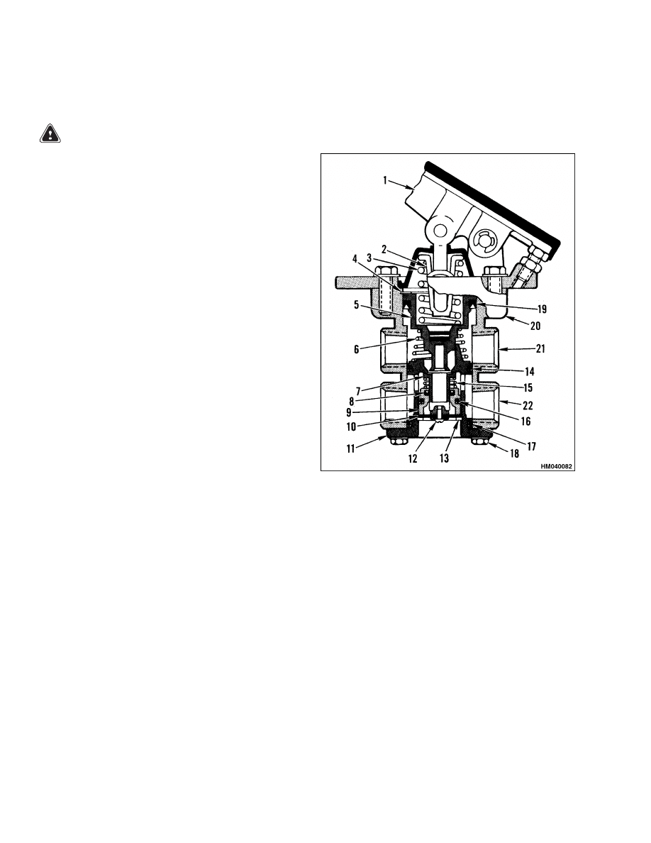
NOTE: ITEMS 7 THROUGH 17 ARE PARTS OF THE
CARTRIDGE.
1.
PEDAL ASSEMBLY
2.
CUP SPRING
3.
BALANCE SPRING
4.
SNAP RING
5.
PISTON
6.
RETURN SPRING
7.
INLET VALVE
8.
SEAL
9.
GUIDE TUBE
10. EXHAUST
DIAPHRAGM
11. CARTRIDGE BODY
12. SCREW
13. SNAP RING
14. O-RING
15. RETURN SPRING
16. O-RING
17. O-RING
18. CAPSCREW (2)
19. PISTON SEAL
20. VALVE BODY
21. OUTLET (TO AIR
CHAMBERS)
22. INLET (FROM
TANK)
Figure 5. Brake Pedal Valve
6

1800 SRM 937
Air Chambers Repair
INSTALL
1.
Install brake pedal valve on floor plate with four
bolts. Connect air lines from manifold. The lines
from the manifold are for the outlet/inlet ports of
the brake valve. See Figure 1.
2.
Connect air line at fitting on manifold. Connect
black wires to pressure switch at manifold as nec-
essary. Connect black wires to pressure switch at
inch/brake pedal as necessary.
3.
Connect air line for pedal valves at fitting toward
back of air tank.
4.
Operate brake system and check brake pedal
valve and lines for leaks.
Air Chambers Repair
REMOVE
WARNING
Put blocks under wheels so the lift truck can-
not move. The parking brakes cannot be ap-
plied after air chambers are removed.
1.
Put blocks under wheels so the lift truck cannot
move.
2.
Use parking brake valve to release parking
brake.
3.
Disconnect clevises on air chambers at actuator
arms. See Table 1 and Figure 6.
4.
Turn adjustment screw (Figure 7) on each actua-
tor arm to move arm away from air chamber. The
piston rods will extend with force when air pres-
sure is released from air chambers.
NOTE: The stroke of the air chamber is as follows:
H8.00-12.00XM (H170-280HD) 63.5 mm (2.5 in.)
H13.00-16.00XM (H300-360HD) 76.2 mm (3.0 in.)
WARNING
Make sure that air pressure is released from air
tank before making repairs to air system. Pull
stem of relief valve to release air.
5.
Apply parking brakes. Release all air pressure
from air tank.
6.
Put tags on air lines. Disconnect air lines at air
chambers. Put caps on open lines.
7.
Remove air chambers from brackets on drive
axle.
DISASSEMBLE
WARNING
The air chamber has a power spring.
The
spring can cause injury if it is suddenly re-
leased. Never disassemble an air chamber un-
til you have manually compressed the power
spring.
To compress the power spring, turn
nut on release bolt until release bolt stops
moving out.
NOTE:
On the H8.00-12.00XM (H170-280HD) mod-
els, the release bolt, washer, and nut are kept in a
receptacle on the air chamber. Securely engage re-
lease bolt in piston before you start to turn nut. See
Figure 6. On H13.00-16.00XM (H300-360HD) mod-
els, the release bolt is installed in the piston.
1.
Use release bolt to fully compress power spring.
2.
Measure or make a mark for position of clevis on
piston rod. Remove clevis, but do not remove jam
nut.
3.
Clean outside of air chamber. Make marks for
alignment on body parts and ring clamps. If ring
clamps are assembled in the wrong position, the
clamps can cause interference during installa-
tion. If air chamber has a breather tube, discon-
nect tube at one of elbows on chamber.
4.
Carefully remove ring clamp for head of air
chamber.
Remove head, release bolt, power
spring, and piston as an assembly.
Remove
diaphragm.
5.
A return spring is compressed between the case
and the service brake chamber. Tighten jam nut
on piston rod against chamber to hold spring.
7
Air Chambers Repair
1800 SRM 937
6.
Carefully remove ring clamp for service brake
chamber. Remove case and diaphragm. Disas-
semble parts of service brake chamber as neces-
sary.
7.
Hold push rod against spring. Remove screw and
plate at bottom of push rod. Remove push rod
and spring from case.
8.
Remove bushings and seal for push rod.
INSPECT
Clean and inspect all parts of air chamber. Replace
worn or damaged parts as necessary.
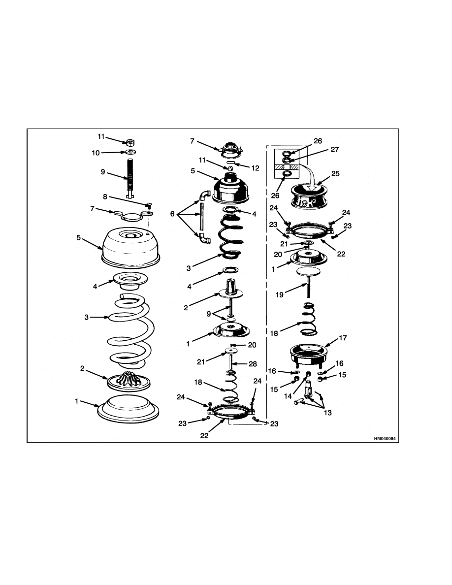
Figure 6. Air Chamber Parts
8

1800 SRM 937
Air Chambers Repair
Legend for Figure 6
1.
DIAPHRAGM
2.
PISTON
3.
POWER SPRING
4.
SPRING GUIDE
5.
HEAD
6.
BREATHER TUBE*
7.
CAP
8.
SCREW
9.
RELEASE BOLT
10. WASHER
11. NUT
12. PIN*
13. CLEVIS
14. JAM NUT
15. LOCK NUT
16. HARDENED WASHER
17. SERVICE BRAKE CHAMBER
18. RETURN SPRING
19. PISTON ROD
20. SCREW
21. PUSH ROD PLATE
22. RING CLAMP
23. NUT
24. BOLT
25. FLANGE CASE
26. PUSH ROD BUSHING
27. PUSH ROD SEAL
28. PUSH ROD
*H13.00-16.00XM (H300-360HD)
ASSEMBLE
NOTE:
If replacing fittings for air lines on the case,
use Teflon
®
tape or pipe sealant on threads. Tighten
fittings to 34 N•m (25 lbf ft) maximum.
1.
Replace seal and bushings for push rod. See Fig-
ure 6. Lightly lubricate these parts with multi-
purpose grease and install parts in case.
2.
Lightly lubricate push rod with multipurpose
grease.
Put return spring in case and install
push rod over spring. Push rod through bore and
install other plate and screw on rod.
3.
Install return spring and piston in service brake
chamber. Use nut for clevis to hold parts.
4.
Make sure that flanges for diaphragm are clean
and smooth. Install diaphragm in case. Install
service brake chamber over diaphragm and then
install ring clamp.
Make sure that you align
marks on parts. Tighten nuts as follows:
H8.00-12.00XM (H170-280HD) 27 to 34 N•m
(20 to 25 lbf ft)
H13.00-16.00XM (H300-360HD) 34 to 47 N•m
(25 to 35 lbf ft)
5.
Make sure that flanges for other diaphragm
are clean and smooth. Install diaphragm over
push rod. Install head assembly on diaphragm
and then install ring clamp. Make sure to align
marks on parts.
Tighten nuts according to
Step 4. Connect breather tube as necessary.
NOTE:
If warning tags were removed during disas-
sembly, install tags on bolts for ring clamp on head
assembly.
6.
Install clevis in its original position on piston rod.
Tighten jam nut to 47 to 68 N•m (35 to 50 lbf).
7.
Release power spring.
On H8.00-12.00XM
(H170-280HD) models, turn nut on release
bolt until release bolt can be removed.
In-
stall release bolt in its receptacle on case. On
H13.00-16.00XM (H300-360HD) models, turn
release bolt all the way into head of air chamber.
Close cap.
INSTALL
1.
Install air chambers on brackets on axle. DO
NOT install flat washers between chambers and
brackets.
Install hardened washers and lock
nuts. Tighten nuts to 135 to 156 N•m (100 to
115 lbf ft).
2.
Connect air lines to air chambers.
3.
Start engine and run engine until air pressure
gauge shows at least 620 kPa (90 psi). Push in
park brake knob to release park brakes.
4.
Use adjustment screw (Figure 7) to move actua-
tor arm to clevis. Connect actuator arm to clevis.
5.
Adjust brakes as described in Brake Shoes Ad-
justment. Check for leaks and check for correct
operation of brake system.
9
Actuator Arms Repair
1800 SRM 937
Actuator Arms Repair
REMOVE
WARNING
Put blocks under wheels so the lift truck can-
not move. Brakes cannot be applied after actu-
ator arms are removed.
1.
Push in park brake knob to release parking
brakes (system must have normal air pressure).
2.
Disconnect actuator arm from clevis on air cham-
ber. See Figure 7.
3.
Turn adjustment screw on actuator arm to move
arm away from clevis.
4.
Remove snap ring and washer(s) from end of
brake camshaft. Pull actuator arm off camshaft.
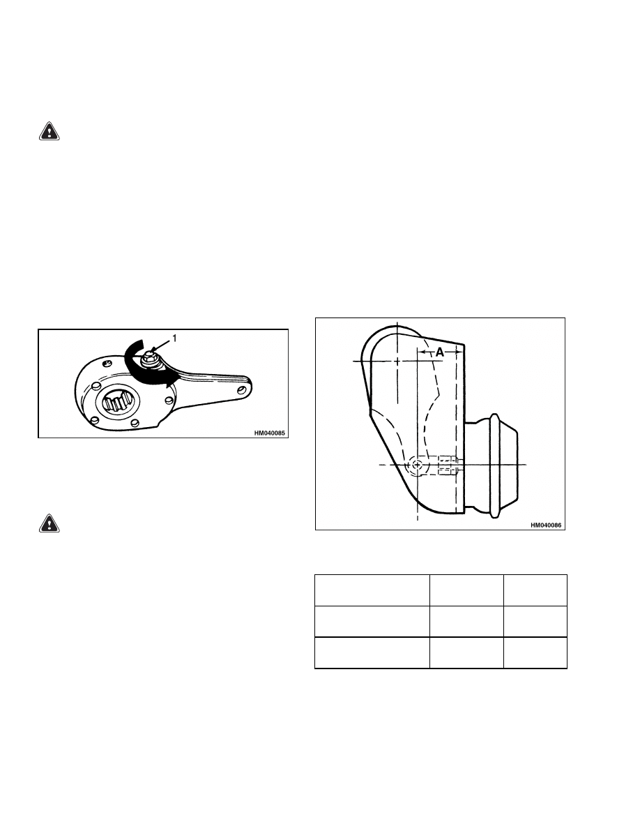
1.
ADJUSTMENT SCREW
Figure 7. Actuator Arm
INSPECT
WARNING
If parking brakes are applied, piston rods of
the air chambers will extend suddenly and can
cause an injury. Apply parking brakes to pre-
vent application of brakes by accident.
Inspect actuator arm for damage. Rotate adjustment
screw to make sure that worm drive operates freely.
Replace actuator arm if worm drive does not operate
correctly. Do not repair actuator arms.
INSTALL
1.
If parking brakes were applied, release parking
brakes to retract piston rods.
2.
Apply antiseize compound to splines of camshaft.
3.
Install actuator arm against washer(s) on brake
camshaft. Use original number of washers. In-
stall washer(s) that was removed from end of
camshaft. Install new snap ring on camshaft.
NOTE:
Add washers as necessary to keep end clear-
ance of camshaft to 1.5 mm (0.060 in.) maximum.
See Figure 18.
4.
Turn adjustment screw until actuator arm has
alignment with clevis. Connect actuator arm to
clevis. See Figure 8 for correct position of actua-
tor arm. Adjust clevis and actuator arm as nec-
essary.
5.
Adjust brakes as described in Brake Shoes Ad-
justment.
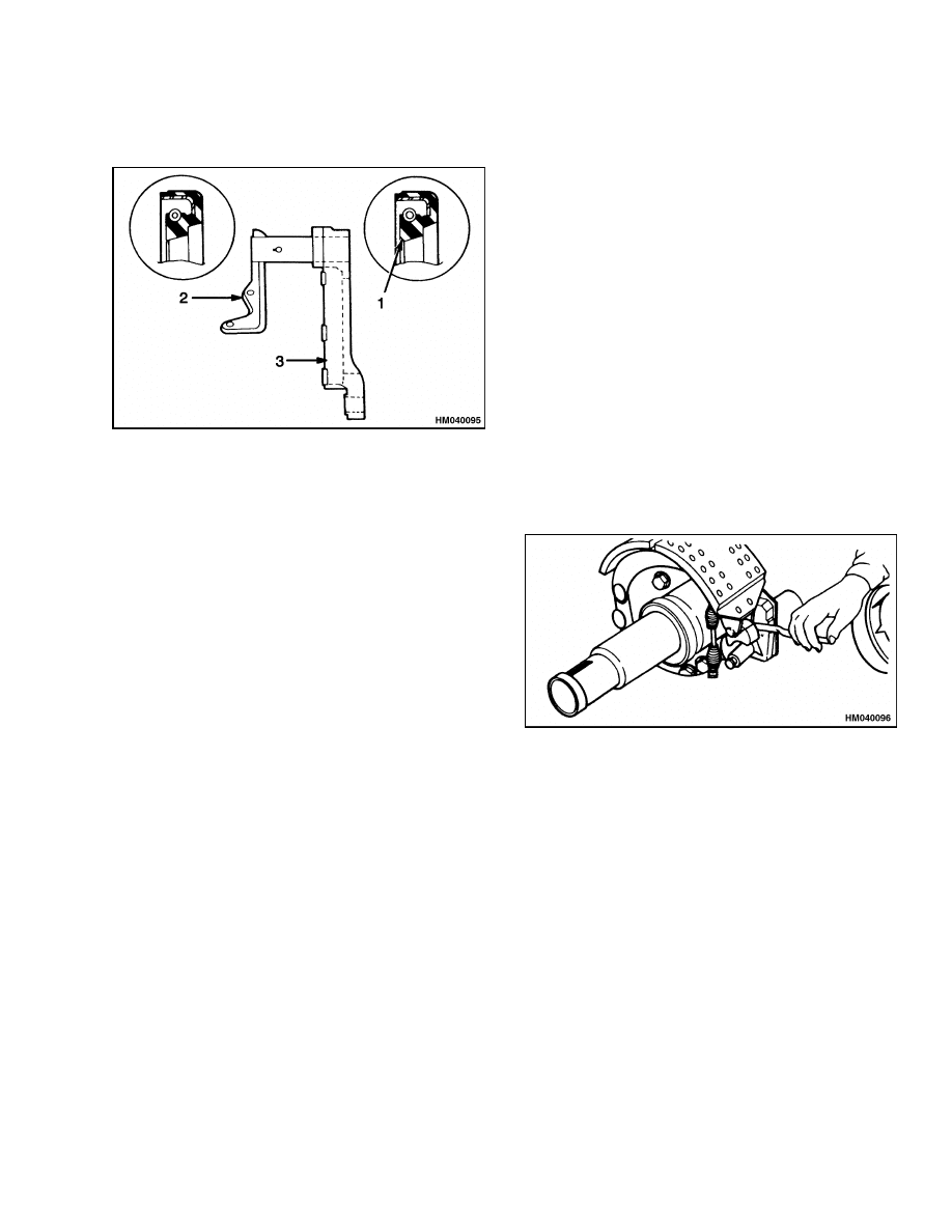
NOTE: A [±1.6 mm (0.063 in.)] IS THE CORRECT PO-
SITION OF THE ACTUATOR ARM.
Model
Chamber
Size
A
H8.00-12.00XM
(H170-280HD)
30
71.0 mm
(2.812 in.)
H13.00-16.00XM
(H300-360HD)
36
66.7 mm
(2.625 in.)
Figure 8. Actuator Arm Installation
10

1800 SRM 937
Brake Assemblies Repair
Brake Assemblies Repair
BRAKE SHOE, REMOVE
WARNING
Brake linings can contain dangerous fibers. In-
haling dust from these brake linings is a cancer
or lung disease hazard. Do not make dust! Do
not clean brake parts with compressed air or
by brushing. Use vacuum equipment approved
for brake dust or follow cleaning procedure in
this section. When brake drums are removed,
do not create dust.
Do not sand, grind, chisel, hammer, or change
linings in any way that will make dust. Any
changes to brake linings must be done in a re-
stricted area with special ventilation. Protec-
tive clothing and a respirator must be used.
1.
Start engine and tilt mast backward. Put blocks
under channels of outer mast. Tilt mast forward
to raise drive wheels from floor. Put blocks under
frame of lift truck.
WARNING
The air chamber has a power spring.
The
spring will apply the brakes if system loses air
pressure. Do not service a brake assembly un-
til you have manually compressed the power
spring.
2.
Apply parking brakes. Use release bolt to com-
press and hold power spring in air chamber. See
Figure 6. Turn nut on release bolt until release
bolt stops moving out.
NOTE:
On H8.00-12.00XM (H170-280HD) models,
release bolt, washer, and nut are kept in a receptacle
on the air chamber. Securely engage release bolt in
piston before you start to turn nut. See Figure 6.
On H13.00-16.00XM (H300-360HD) models, release
bolt is installed in the piston.
3.
Turn adjustment screw on actuator arm so that
the clearance increases between brake shoes and
drum. Turn screw until brake shoes are fully
retracted.
4.
Remove drive wheels. Use the procedure in the
section Periodic Maintenance for your lift
truck.
5.
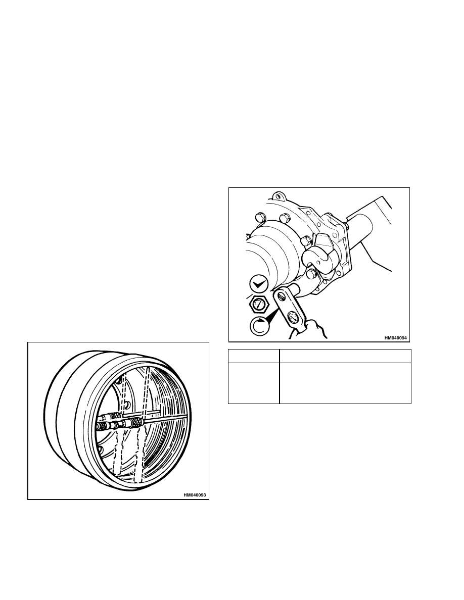
Remove brake drum. Use capscrews in threaded
holes to push drum from hub. Do not release
dust from brake linings into air when drum is
removed. See Clean, to clean drum and other
brake parts.
6.
Remove snap rings, retainers, and felt washers
from anchor pins. See Figure 9.
7.
Cut lock wire and remove capscrews that hold
anchor pins.
WARNING
Wear eye protection. Do not hit steel parts with
a steel hammer. Parts can break and cause in-
jury.
8.
Use a brass drift to remove top anchor pin. See
Figure 10.
9.
Rotate top shoe to release tension of return
spring. Remove shoe. See Figure 11.
10. Remove bottom anchor pin (see Step 8) and sec-
ond shoe.
11. Release retainers for rollers and remove rollers
from brake shoes. See Figure 12.
11

Brake Assemblies Repair
1800 SRM 937
1.
BRAKE CAMSHAFT
2.
THRUST WASHER
3.
SEAL
4.
BUSHING
5.
CAPSCREW
6.
WASHER
7.
SPIDER
8.
GASKET
9.
CAMSHAFT BRACKET
10. GREASE FITTING
11. WASHER
12. CAPSCREW
13. CLAMP
14. CAPSCREW
15. WASHER
16. ACTUATOR ARM
17. WASHER
18. SNAP RING
19. RETAINER
20. ROLLER
21. RETURN SPRING
22. PIN
23. BRAKE SHOE
24. BRAKE SHOE LINING
25. RIVET
26. SNAP RING
27. ANCHOR PIN RETAINER
28. FELT WASHER
29. BRAKE ANCHOR PIN
30. CAPSCREW
31. LOCK WIRE
32. BUSHING
33. LOCKWASHER
34. CAPSCREW
35. DUST SHIELD
Figure 9. Brake Assembly
Figure 10. Top Anchor Pin Removal
Figure 11. Shoe Removal
12
1800 SRM 937
Brake Assemblies Repair
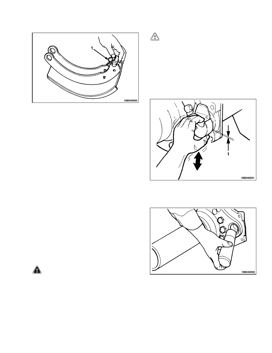
1.
RETAINER
Figure 12. Roller Removal
CAMSHAFT, REMOVE
1.
Remove brake shoes. See Brake Shoe, Remove.
2.
Disconnect actuator arm at clevis on air chamber.
3.
Remove snap ring and washer(s) from end of
camshaft. Pull actuator arm off camshaft. See
Figure 9.
4.
Check for wear at camshaft bushings as shown
in Figure 13. If radial clearance of camshaft is
more than 0.76 mm (0.030 in.) on a dial indi-
cator setup, replace bushings. See the section
Planetary Drive Axle 1400 SRM 945 to remove
planetary hub. Remove washer(s) and seal from
camshaft and pull camshaft from spider. Use a
driver of the correct size to remove bushings from
spider and bracket. See Figure 14.
5.
Remove thrust washer and seal from camshaft.
CLEAN
1.
Carefully remove brake drum. Do not release
dust from brake linings into air when brake drum
is removed.
WARNING
Cleaning solvents can be flammable and toxic
and can cause skin irritation.
When using
cleaning solvents, always follow the solvent
manufacturer’s recommended safety precau-
tions.
CAUTION
Do not use an oil solvent to clean wheel cylin-
der.
Use a solvent approved for cleaning of
brake parts.
Do not permit oil or grease in
brake fluid or on brake linings.
2.
Use a solvent approved for cleaning of brake
parts to wet brake lining dust. Follow instruc-
tions and cautions of the manufacturer for use
of solvent. If solvent spray is used, do not make
brake lining dust with spray.
1.
RADIAL CLEARANCE MEASUREMENT
Figure 13. Camshaft Bushing Wear Check
Figure 14. Bushing Removal
13
Brake Assemblies Repair
1800 SRM 937
3.
When brake lining dust is wet, clean parts. Put
any rags or towels in a plastic bag or an airtight
container while they are still wet. Put a DAN-
GEROUS FIBERS warning label on plastic bag
or airtight container.
4.
Any cleaning rags that will be washed must be
cleaned so that fibers are not released into the
air.
INSPECT
1.
Inspect spider, camshaft, rollers, anchor pins,
and return spring for wear and damage. Check
for expanded holes for pins, worn bushings,
broken welds, cracks, corrosion, and incorrect
alignment. Replace worn or damaged parts.
2.
Inspect brake shoes. Check for wear at holes for
anchor pins and notches for rollers. Also check
for rust, loose rivets, broken welds, and incorrect
alignment. Replace brake shoes that have dam-
age. Replace brake shoes or linings when thick-
ness of linings is no more than 6.35 mm (0.25 in.)
at thinnest point. Always replace brake shoes or
linings as sets.
3.
Inspect brake drum as follows:
a. Check for deep grooves, cracks, distortion,
and other damage. Replace drum that has
damage.
Figure 15. Brake Drum Measurement
b. Measure inside diameter of drum at several
locations with drum caliper or micrometer.
See Figure 15. The maximum inside diam-
eter of the 419.1 mm (16.5 in.) brake drum,
including wear, is 422.15 mm (16.620 in.). If
diameter is larger than this maximum, re-
place brake drum. If brake drums require
grinding, never grind more than 2.03 mm
(0.080 in.) from diameter.
CAMSHAFT, INSTALL
1.
Make sure that capscrews for spider have correct
torque. See Figure 16.
Bolt Size
Torque
7/16"-20
1/2"-20
9/16"-18
5/8"-18
81 to 102 N•m (60 to 75 lbf ft)
115 to 156 N•m (85 to 115 lbf ft)
176 to 224 N•m (130 to 165 lbf ft)
244 to 312 N•m (180 to 230 lbf ft)
Figure 16. Spider Capscrews Torque
2.
If camshaft bracket was removed, install gasket
and bracket on spider. Tighten capscrews as fol-
lows:
Grade 5 = 88 to 136 N•m (65 to 100 lbf ft)
Grade 8 = 122 to 163 N•m (90 to 120 lbf ft)
3.
Install new bushings for camshaft in spider and
bracket if necessary. Use driver of correct size.
See Figure 14.
14
1800 SRM 937
Brake Assemblies Repair
4.
Install new seals for camshaft. Install both seals
as shown in Figure 17.
1.
LIP OF SEAL
2.
BRACKET
3.
SPIDER
Figure 17. Seal Installation
5.
Put thrust washer on camshaft. Apply multipur-
pose grease to journals of camshaft and bushings.
Carefully install camshaft through spider and
bracket. Make sure that camshaft turns freely
in bushings.
6.
Install planetary gear assembly.
BRAKE SHOE, INSTALL
1.
Install rollers and retainers on brake shoes. See
Figure 12.
2.
Install new bushings for anchor pins in spider
if necessary. Make sure that holes in bushings
have alignment with holes for capscrews that
hold pins.
3.
Put lower brake shoe on spider. Use brass drift
to install anchor pin. Make sure that flat on pin
has alignment with hole for capscrew.
4.
Install felt washers, retainers, and snap rings for
anchor pin. Install capscrew and tighten it to
13.5 N•m (10 lbf ft) minimum.
5.
Install return spring between brake shoes. See
Figure 11. Move upper shoe over spider and in-
stall anchor pin as in Step 3. Repeat Step 4.
6.
Install lock wire in capscrews for anchor pins.
7.
Apply antiseize compound to splines of camshaft.
Install inner washer(s) and actuator arm on
camshaft. Install outer washer(s) and snap ring.
NOTE:
Add washers as necessary to keep end clear-
ance of camshaft to 1.5 mm (0.060 in.) maximum.
See Figure 18.
8.
Connect actuator arm at clevis on air chamber.
Use adjustment screw to move actuator arm as
necessary. See Figure 8 for correct position of
actuator arm after installation. Adjust clevis and
actuator arm as necessary.
Figure 18. Camshaft End Clearance
9.
Install brake drum and drive wheels.
10. Adjust brakes according to the procedure in
15

Air Dryer
1800 SRM 937
Air Dryer
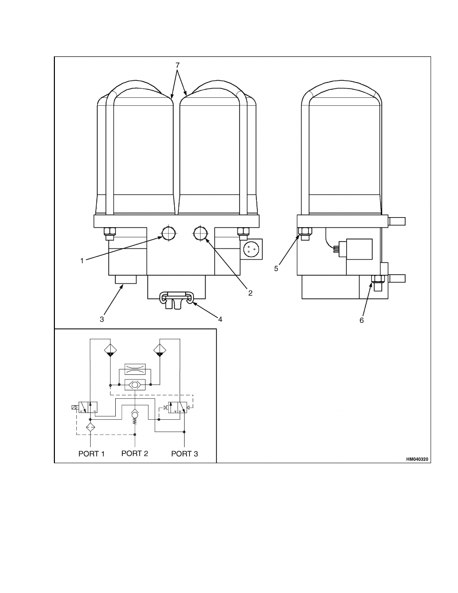
DESCRIPTION
The optional air dryer is for drying of the com-
pressed air supplied by the compressor by extracting
the moisture present in the air. See Figure 19.
CARTRIDGE
Remove
NOTE:
The air dryer is located on the right side of the
engine mounted to the frame.
1.
Lower the mast.
2.
Shut down engine.
3.
Operate quick release valve to remove air pres-
sure.
CAUTION
First remove nut installed on short leg side-end
of the bracket.
4.
Remove nuts holding bracket.
5.
Remove cartridge and O-ring.
Install
1.
Install new O-rings and cartridge.
2.
Replace nuts on bracket.
NOTE: The part number for the cartridge includes
the required O-rings.
FILTER
Remove
1.
Lower the mast.
2.
Shut down engine.
3.
Operate quick release valve to remove air pres-
sure.
4.
Release spring and pull out filter.
Install
1.
Push in filter.
2.
Replace spring.
16
1800 SRM 937
Air Dryer
1.
PORT 1 (SUPPLY)
2.
PORT 2 (DELIVERY)
3.
PORT 3 (EXHAUST)
4.
SPRING
5.
SHORT SIDE BRACKET NUTS (OPPOSITE SIDE
NOT SHOWN)
6.
LONG SIDE BRACKET NUTS (OPPOSITE SIDE
NOT SHOWN)
7.
CARTRIDGES
Figure 19. Air Dryer
17
Governor Check and Adjustment for Air Compressor
1800 SRM 937
Quick-Release Valve
WARNING
Make sure that air pressure is released from air
tank before making repairs to air system. Pull
stem of relief valve to release air.
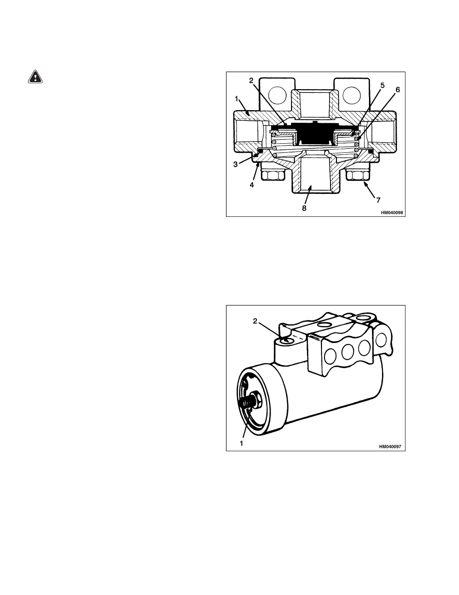
The quick-release valve is installed on the mounting
plate with the main control valve. See Figure 20.
The valve can be serviced without removal. Carefully
remove cover to inspect parts or replace diaphragm.
Replace quick-release valve if seat of exhaust port
has damage such as broken pieces or deep scratches.
1.
BODY
2.
DIAPHRAGM
3.
O-RING
4.
COVER
5.
PLATE
6.
SPRING
7.
CAPSCREW (4)
8.
EXHAUST PORT
Figure 20. Quick-Release Valve
Governor Check and Adjustment for Air Compressor
1.
Start engine.
When governor is correctly ad-
justed, air will be released from exhaust port
when air pressure gauge indicates 862 kPa
(125 psi). The governor is installed next to air
tank above axle.
2.
If air pressure does not reach 862 kPa (125 psi),
turn adjustment screw clockwise to increase
pressure. See Figure 21. Turn adjustment screw
counterclockwise to decrease pressure.
The governor also must cause air pressure to in-
crease when air pressure has decreased to less than
724 kPa (105 psi). Replace a governor that does not
operate correctly.
1.
ADJUSTMENT
SCREW
2.
EXHAUST PORT
Figure 21. Governor Adjustment
18
1800 SRM 937
Brake Shoes Adjustment
Brake Shoes Adjustment
WARNING
Put blocks under wheels so the lift truck can-
not move when parking brakes are released.
1.
Release parking brakes. Apply and release ser-
vice brakes several times.
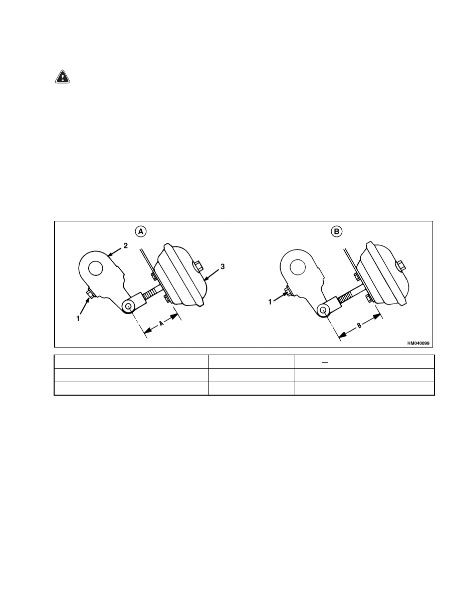
2.
Measure distance A when service brakes are
released.
Apply service brakes and measure
distance B. Brake air pressure must be at least
586 kPa (85 psi) for this measurement.
3.
Subtract A from B and compare remainder with
table in Figure 22. If the remainder is less than
the value in the table, brake adjustment is not
necessary. If the remainder is equal to or more
than the value in the table, adjust brakes as fol-
lows:
a. For the first adjustment, turn adjustment
screw on actuator arm until brake lining
touches drum.
b. Turn adjustment screw in opposite direction.
Turn adjustment screw for only one or two
clicks to get minimum clearance at lining.
Rotate drum to check clearance when that
procedure is possible.
NOTE: The lining at the center of the shoe moves
0.06 mm (0.0025 in.) when adjustment screw is ro-
tated 90 degrees.
Model
Chamber Size
B
A Must Be Less Than:
H8.00-12.00XM (H170-280HD)
24
5.08 cm (2.0 in.)
H13.00-16.00XM (H300-360HD)
30
6.35 cm (2.5 in.)
A. BRAKES OFF
B. BRAKES ON
1.
ADJUSTMENT SCREW
2.
ACTUATOR ARM
3.
AIR CHAMBER (TYPICAL)
Figure 22. Brakes Adjustment Check
19

Specifications
1800 SRM 937
Specifications
GOVERNOR CYCLE
Compressor ON
724 kPa (105 psi)
Compressor OFF
862 kPa (125 psi)
RELIEF VALVE SETTING
1034 kPa (150 psi)
LOW AIR PRESSURE WARNING
483 kPa (70 psi) (Later Production)
BRAKES
Size
H8.00-12.00XM (H170-280HD)
419.1 × 127.0 mm (16.5×5 in.)
H13.00-16.00XM (H300-360HD)
419.1 × 177.8 mm (16.5×7 in.)
Drum
Maximum inside diameter, including wear
422.15 mm (16.620 in.)
TORQUE VALUES
Air Fittings in Air Chambers
34 N•m (25 lbf ft) Maximum
Nuts, Air Chamber Ring Clamps
H8.00-12.00XM (H170-280HD)
27 to 34 N•m (20 to 25 lbf ft)
H13.00-16.00XM (H300-360HD)
34 to 47 N•m (25 to 35 lbf ft)
Jam Nut, Clevis
47 to 68 N•m (35 to 50 lbf ft)
Lock Nuts, Air Chamber Studs
13.5 N•m (10 lbf ft) Minimum
Capscrew, Brake Anchor Pin
13.5 N•m (10 lbf ft) Minimum
Capscrew, Spider
See Figure 16.
Capscrew, Camshaft Bracket
Grade 5
88 to 136 N•m (65 to 100 lbf ft)
Grade 8
122 to 163 N•m (90 to 120 lbf ft)
20

1800 SRM 937
Troubleshooting
Troubleshooting
PROBLEM
POSSIBLE CAUSE
PROCEDURE OR ACTION
SERVICE BRAKES
Brakes do no apply enough
force to stop lift truck, or
brakes do not operate.
Brake shoes are not correctly ad-
justed.
Adjust brake shoes.
Linings or drums have excessive
wear.
Install new brake shoes.
Oil or grease is on brake linings.
Clean linings or install new brake
shoes.
Air compressor has a defect.
Repair or replace air compressor.
Air system (lines, fittings, tank
valves, ring clamps on air cham-
bers) has leaks.
Replace or repair defective compo-
nent to seal air system.
Air lines have restrictions.
Repair or replace air lines.
Governor has a defect or incorrect
adjustment.
Repair or adjust governor.
Brake pedal valve has a defect.
Repair or replace valve.
Quick-release valve has a defect (air
leak).
Repair or replace valve.
Defective diaphragm(s) in air cham-
ber(s).
Replace diaphragm(s).
Actuator arm(s) is defective or incor-
rectly installed.
Replace or adjust actuator arm.
Bent
or
broken
air
chamber
bracket(s).
Replace air chamber bracket.
Defective or incorrect brake shoe(s).
Install new brake shoes.
A camshaft has damage or does not
rotate freely.
Repair or replace damaged camshaft.
A brake drum is not round.
Repair or install a new brake drum.
Oil or water is in air system.
Remove oil or water from air system.
Brakes
apply
force
too
quickly.
Brake pedal valve has a defect.
Repair or replace valve.
21

Troubleshooting
1800 SRM 937
PROBLEM
POSSIBLE CAUSE
PROCEDURE OR ACTION
Lift truck pulls to one side
when brakes are applied.
Brake linings have different friction
materials.
Install new brake shoes.
One brake assembly has damage or
incorrect adjustment.
Repair damage or adjust brakes.
Oil or grease is on one set of linings.
Clean lining or install new brake
shoes.
One air chamber has a defect.
Repair or replace air chamber.
An air line for an air chamber has a
leak or restriction.
Install new brake lines.
A brake drum has a defect.
Install new brake drum.
Tires do not have equal inflation.
Inflate tires properly.
Brakes do not release or re-
lease too slowly.
Brake pedal valve has a defect.
Repair or replace valve.
A shoe return spring is broken.
Install new spring.
A piston return spring (in air cham-
ber) is broken.
Install new spring.
Air leakage from spring chamber(s)
at push rod seal(s).
Replace seals.
A camshaft(s) does not rotate freely.
Repair damaged camshaft.
Air lines have restrictions.
Install new brake lines.
Quick-release valve has a defect.
Replace or repair valve.
Exhaust
ports
of
pedal
valves have air leakage (all
brakes released).
Air leakage from spring chamber(s)
at push rod seal(s).
Replace seals.
Brake pedal valve has a defective
seal.
Repair or replace valve.
22

1800 SRM 937
Troubleshooting
PROBLEM
POSSIBLE CAUSE
PROCEDURE OR ACTION
SERVICE BRAKES, PARK FUNCTION
(REVIEW CAUSES UNDER SERVICE BRAKES ALSO)
Parking brake does not re-
lease.
Air pressure is too low.
Repair or replace compressor or leak-
age.
Parking brake valve has a defect.
Repair or replace valve.
Parking brake electrical switch is de-
fective.
Replace electrical switch.
Spring chamber(s) has a defective di-
aphragm or leak.
Replace diaphragm.
Parking brake does not ap-
ply enough force to hold lift
truck.
Brake shoes are not correctly ad-
justed.
Adjust brakes.
Linings or drums have excessive
wear.
Install new brake shoes.
Parking brake valve has a defect.
Replace valve.
Spring(s) in air chamber(s) is broken.
Replace spring(s).
A release bolt keeps a spring par-
tially compressed.
Adjust release bolt.
23

NOTES
____________________________________________________________
____________________________________________________________
____________________________________________________________
____________________________________________________________
____________________________________________________________
____________________________________________________________
____________________________________________________________
____________________________________________________________
____________________________________________________________
____________________________________________________________
____________________________________________________________
____________________________________________________________
____________________________________________________________
____________________________________________________________
____________________________________________________________
____________________________________________________________
____________________________________________________________
____________________________________________________________
____________________________________________________________
____________________________________________________________
24


TECHNICAL PUBLICATIONS
1800 SRM 937
12/03 (9/03)(7/02)(2/01) Printed in United Kingdom
Document Outline
- toc
- Dry Brake System
- Safety Precautions Maintenance and Repair
- General
- Description
- Operation
- Air Tank Repair
- Brake Pedal Valve Repair
- Air Chambers Repair
- Actuator Arms Repair
- Brake Assemblies Repair
- Air Dryer
- Quick-Release Valve
- Governor Check and Adjustment for Air Compressor
- Brake Shoes Adjustment
- Specifications
- Troubleshooting
- tables
Wyszukiwarka
Podobne podstrony:
1494145 8000SRM0940 (10 2003) UK EN
1466211 2000SRM0754 (12 2003) UK EN
1494143 2200SRM0939 (12 2004) UK EN
1475871 1800SRM0785 (11 2003) UK EN
897987 1800SRM0659 (09 2003) UK EN
1483865 8000SRM0916 (12 2003) UK EN
1494140 1600SRM0936 (09 2003) UK EN
897109 1800SRM0327 (09 2003) UK EN
897653 1800SRM0566 (04 2005) UK EN
1452929 2200SRM0679 (11 2003) UK EN
więcej podobnych podstron