BRAKE SYSTEM
YARDMASTER®
HR45-25, HR45-27, HR45-31, HR45-40S,
HR45-36L, HR45-40LS, HR45-45LSX,
HR45H [A227, B227]
PART NO. 1475871
1800 SRM 785

SAFETY PRECAUTIONS
MAINTENANCE AND REPAIR
• When lifting parts or assemblies, make sure all slings, chains, or cables are correctly
fastened, and that the load being lifted is balanced. Make sure the crane, cables, and
chains have the capacity to support the weight of the load.
• Do not lift heavy parts by hand, use a lifting mechanism.
• Wear safety glasses.
• DISCONNECT THE BATTERY CONNECTOR before doing any maintenance or repair
on electric lift trucks.
• Disconnect the battery ground cable on internal combustion lift trucks.
• Always use correct blocks to prevent the unit from rolling or falling. See HOW TO PUT
THE LIFT TRUCK ON BLOCKS in the Operating Manual or the Periodic Mainte-
nance section.
• Keep the unit clean and the working area clean and orderly.
• Use the correct tools for the job.
• Keep the tools clean and in good condition.
• Always use HYSTER APPROVED parts when making repairs. Replacement parts
must meet or exceed the specifications of the original equipment manufacturer.
• Make sure all nuts, bolts, snap rings, and other fastening devices are removed before
using force to remove parts.
• Always fasten a DO NOT OPERATE tag to the controls of the unit when making repairs,
or if the unit needs repairs.
• Be sure to follow the WARNING and CAUTION notes in the instructions.
• Gasoline, Liquid Petroleum Gas (LPG), Compressed Natural Gas (CNG), and Diesel fuel
are flammable. Be sure to follow the necessary safety precautions when handling these
fuels and when working on these fuel systems.
• Batteries generate flammable gas when they are being charged. Keep fire and sparks
away from the area. Make sure the area is well ventilated.
NOTE:
The following symbols and words indicate safety information in this
manual:
WARNING
Indicates a condition that can cause immediate death or injury!
CAUTION
Indicates a condition that can cause property damage!

Brake System YardMaster
®
Table of Contents
TABLE OF CONTENTS
General ...............................................................................................................................................................
Description and Operation ................................................................................................................................
Service Brakes ...............................................................................................................................................
Parking Brake................................................................................................................................................
Pump for Brake System ................................................................................................................................
Oil Cooler Circuit...........................................................................................................................................
Pressure Switch Replacement...........................................................................................................................
Accumulator Replacement.................................................................................................................................
Brake Pedal Valves Repair ................................................................................................................................
Remove and Disassemble ..............................................................................................................................
Clean and Inspect ..........................................................................................................................................
Assemble and Install .....................................................................................................................................
Parking Brake Valve Repair..............................................................................................................................
Remove ...........................................................................................................................................................
Clean and Inspect ..........................................................................................................................................
Repairs ...........................................................................................................................................................
Install .............................................................................................................................................................
Parking Brake Caliper Repair ..........................................................................................................................
Remove ...........................................................................................................................................................
Disassemble ...................................................................................................................................................
Clean ..............................................................................................................................................................
Inspect ............................................................................................................................................................
Assemble ........................................................................................................................................................
Install and Adjust ..........................................................................................................................................
Service Brake Assembly Repair ........................................................................................................................
Remove ...........................................................................................................................................................
Disassemble ...................................................................................................................................................
Clean ..............................................................................................................................................................
Inspect ............................................................................................................................................................
Assemble ........................................................................................................................................................
Install .............................................................................................................................................................
Brake System Air Removal ...............................................................................................................................
Service Brakes Wear Check...............................................................................................................................
Oil Cooler Circuit Adjustment ..........................................................................................................................
Troubleshooting..................................................................................................................................................
This section is for the following models:
HR45-25, HR45-27, HR45-31, HR45-40S, HR45-36L, HR45-40LS,
HR45-45LSX, HR45H [A227, B227]
©2004 HYSTER COMPANY
i

"THE
QUALITY
KEEPERS"
HYSTER
APPROVED
PARTS

1800 SRM 785
Description and Operation
General
These vehicles have oil-cooled brakes. This section
has the description, operation, and some repair pro-
cedures for the components of the brake system.
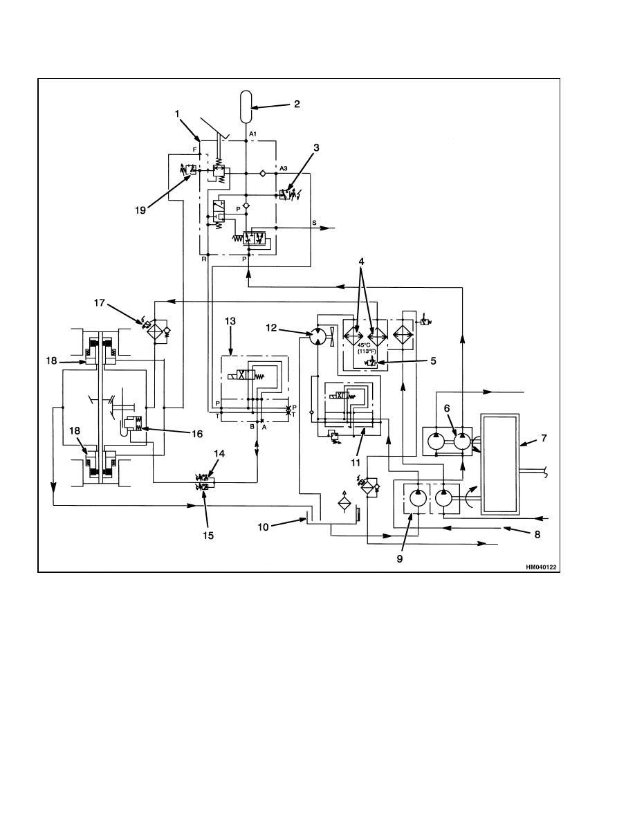
The main parts of the system are a hydraulic pump,
brake pedal valves, accumulator, solenoid valves,
and the brake parts on the drive axle. See Figure 1.
Description and Operation
A hydraulic pump supplies the oil to operate the
brake system. See Figure 1 and Figure 2.
The oil from the pump goes to the relief valve at the
brake pedal valve. At the relief valve, the oil goes to
the accumulator, brake pedal valve, and the parking
brake solenoid. Oil that is not needed by the brake
circuit flows to the attachment circuit. There is a
pressure switch connected to the brake circuit that
activates a warning light when brake pressure is be-
low 105 bar (1523 psi). The accumulator stores oil
under pressure to operate the brakes when the en-
gine is not running.
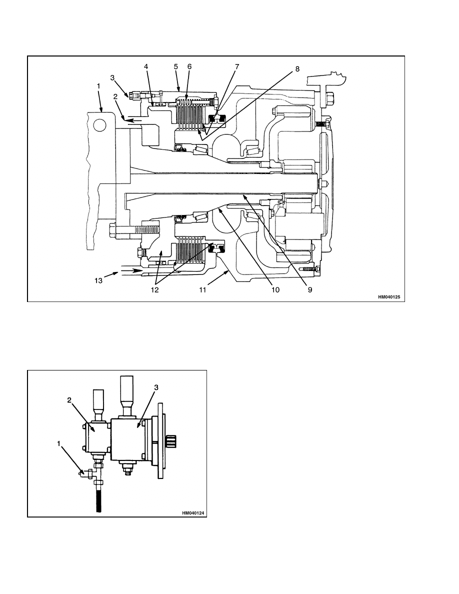
SERVICE BRAKES
There is an oil-cooled brake assembly at each drive
wheel as shown in Figure 3. There are discs that ro-
tate with the wheel hub and stationary discs. The
discs are assembled so that there is a friction (ro-
tating) disc between each stationary disc. A piston,
moved by hydraulic pressure, pushes the discs to-
gether for the braking action. A separate oil system
circulates oil through the sealed case to cool the discs.
The service brake pedal controls the flow of oil to the
service brakes. The inching brake pedal controls the
flow of oil to the service brakes and the declutch con-
trol at the transmission.
PARKING BRAKE
The parking brake system uses a disc brake that is
installed at the rear of the differential. See Figure 1.
The spring-applied caliper is installed on the differ-
ential housing with the brake rotor on the pinion
shaft.
The operation of the parking brake is controlled by a
solenoid valve for the parking brake. The solenoid is
operated by a switch on the instrument panel. The
solenoid is normally energized during operation for
oil pressure to compress the spring to release the
parking brake. The solenoid valve gets its oil from
the relief valve. Oil flows from the relief valve at a
minimum of 105 bar (1523 psi). This oil causes the
brake caliper to open against the spring pressure and
to release the parking brake.
There are two pressure switches controlled by the
parking brake circuit. When the parking brake is ap-
plied, one switch activates the indicator light for the
parking brake and the other switch shifts the trans-
mission to NEUTRAL.
PUMP FOR BRAKE SYSTEM
The pump for the service and parking brakes and
hydraulic system is a gear pump with two sections.
See Figure 1. The large section of the pump supplies
oil for the brake system. (The small section of the
pump supplies oil to operate the hydraulic fan motor
for the engine radiator. Oil from this section also goes
to the main control valve.)
OIL COOLER CIRCUIT
When the oil temperature in the brake system is be-
low 45 C (113 F), the flow from the cooling pump goes
through the oil coolers. See Figure 1. When the oil
temperature is above 45 C (113 F), the temperature
switch activates the oil cooler solenoid. When the so-
lenoid opens, oil from the brake system cooling pump
drives the hydraulic fan motor. See Figure 4.
1
Description and Operation
1800 SRM 785
1.
BRAKE PEDAL VALVE
2.
ACCUMULATOR
3.
LOW-PRESSURE SWITCH
4.
OIL COOLER
5.
THERMOSTATIC SWITCH
6.
HYDRAULIC PUMP
7.
ENGINE
8.
FROM HYDRAULIC SYSTEM TANK
9.
COOLING CIRCUIT PUMP
10. BRAKE SYSTEM TANK
11. OIL COOLER SOLENOID VALVE
12. HYDRAULIC FAN MOTOR
13. PARKING BRAKE SOLENOID VALVE
14. DECLUTCH SWITCH
15. WARNING LIGHT SWITCH
16. PARKING BRAKE CALIPER
17. OIL FILTER
18. SERVICE BRAKES
19. BRAKE LIGHT SWITCH
Figure 1. Brake System Schematic
2
1800 SRM 785
Description and Operation
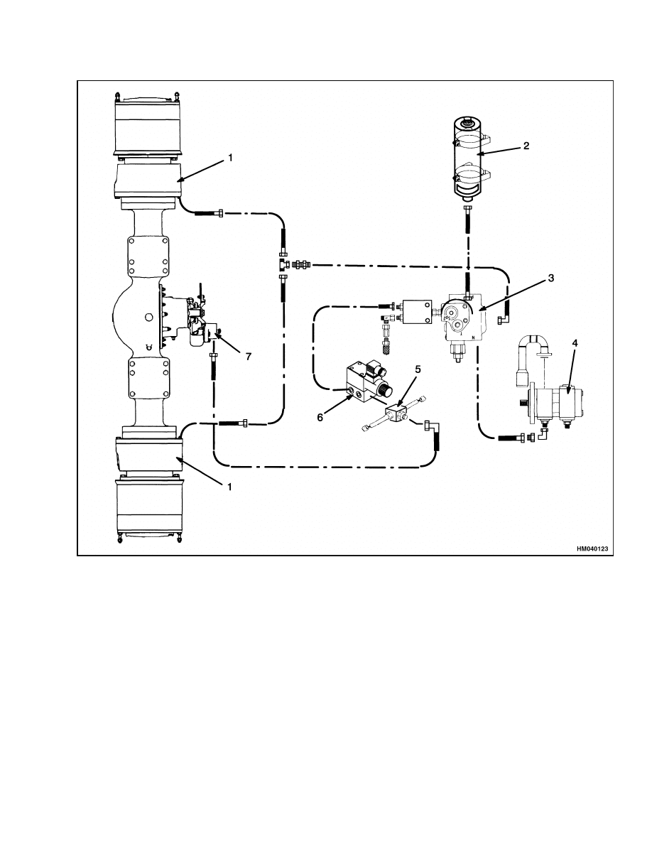
1.
SERVICE BRAKE
2.
ACCUMULATOR
3.
BRAKE PEDAL VALVE
4.
HYDRAULIC PUMP
5.
PRESSURE SWITCH
6.
PARKING BRAKE VALVE
7.
PARKING BRAKE CALIPER
Figure 2. Brake System Arrangement
3
Description and Operation
1800 SRM 785
1.
AXLE HOUSING
2.
COOLING OIL RETURN
3.
BRAKING PRESSURE LINE
4.
PISTON
5.
BRAKE HOUSING
6.
RETURN SPRING
7.
STATIONARY DISCS
8.
FRICTION (ROTATING) DISCS
9.
AXLE SHAFT
10. SPINDLE
11. HUB
12. COOLING OIL
13. COOLING OIL SUPPLY
Figure 3. Service Brake
Figure 4. Oil Cooler Circuit Pump
Legend for Figure 4
1.
PRESSURE PLUG
2.
BRAKE SYSTEM
PUMP
3.
HYDRAULIC
SYSTEM PUMP
4

1800 SRM 785
Brake Pedal Valves Repair
Pressure Switch Replacement
WARNING
Before disconnecting any hydraulic lines, re-
lease pressure from the hydraulic circuit as fol-
lows:
1.
Shut the engine off and completely lower
the boom. Install blocks at the wheels to
prevent the vehicle from moving.
2.
Operate the brake pedal until the hydraulic
pressure is released.
1.
Put tags for identification on the lines. Discon-
nect lines from switch. Disconnect electrical con-
nector. Put caps on open lines.
2.
Install new switch. Connect hydraulic lines and
connector at switch.
3.
Remove air from hydraulic system and check
pressure at switch as described in Brake System
Air Removal.
Accumulator Replacement
WARNING
The accumulator has a pressure charge and
can cause an injury if the pressure is released
too fast.
Follow the manufacturer’s instruc-
tions during removal and installation.
Before disconnecting any hydraulic lines, re-
lease pressure from the hydraulic circuit as fol-
lows:
• Shut off the engine and completely lower the
boom. Install blocks at the wheels to prevent
the vehicle from moving.
• Operate the brake pedal until the hydraulic
pressure is released.
1.
Put tags for identification on the lines. Slowly
disconnect hydraulic lines from accumulator to
release any pressure slowly. Put caps on open
lines. Remove accumulator.
2.
Follow the manufacturer’s instructions during
installation of the new accumulator.
Tighten
bracket nuts. Connect lines.
3.
Operate system and check for leaks.
Brake Pedal Valves Repair
REMOVE AND DISASSEMBLE
WARNING
Before disconnecting any hydraulic lines, re-
lease pressure from the hydraulic circuit as fol-
lows:
1.
Shut off the engine and completely lower
the boom. Install blocks at the wheels to
prevent the vehicle from moving.
2.
Operate the brake pedal until the hydraulic
pressure is released.
1.
Put tags for identification on the lines. Discon-
nect lines from brake pedal valve. Put caps on
open lines.
2.
If pedal assembly will be repaired or replaced,
remove screws that fasten assembly to mount
plate.
CLEAN AND INSPECT
WARNING
Cleaning solvents can be flammable and toxic,
and can cause skin irritation.
When using
cleaning solvents, always follow the solvent
manufacturer’s recommended safety precau-
tions.
Clean the parts in solvent. Inspect spool and bores
for scratches. If there are scratches or other damage,
parts must be replaced. Lubricate parts with clean
hydraulic oil for assembly.
5
Parking Brake Valve Repair
1800 SRM 785
ASSEMBLE AND INSTALL
1.
Install valve assembly using capscrews that fas-
ten valve assembly to mount plate.
2.
Install lines to brake pedal valve.
3.
Operate system and check valve connections for
leaks. Remove air from hydraulic system as de-
scribed in Brake System Air Removal.
Parking Brake Valve Repair
REMOVE
WARNING
Before disconnecting any hydraulic lines, re-
lease pressure from the hydraulic circuit as fol-
lows:
• Shut off the engine and completely lower the
boom. Install blocks at the wheels to prevent
the vehicle from moving.
• Operate the brake pedal until the hydraulic
pressure is released.
1.
Put blocks in front and back of tires so vehicle
cannot move.
2.
Disconnect electrical connector.
Put tags for
identification on hydraulic lines.
3.
Disconnect lines from parking brake valve. Put
caps on open lines. Remove valve.
CLEAN AND INSPECT
WARNING
Cleaning solvents can be flammable and toxic,
and can cause skin irritation.
When using
cleaning solvents, always follow the solvent
manufacturer’s recommended safety precau-
tions.
Clean parts in solvent. Inspect parts and bores for
scratches. Replace valve if there are scratches or
other damage. Lubricate parts with clean hydraulic
oil for assembly.
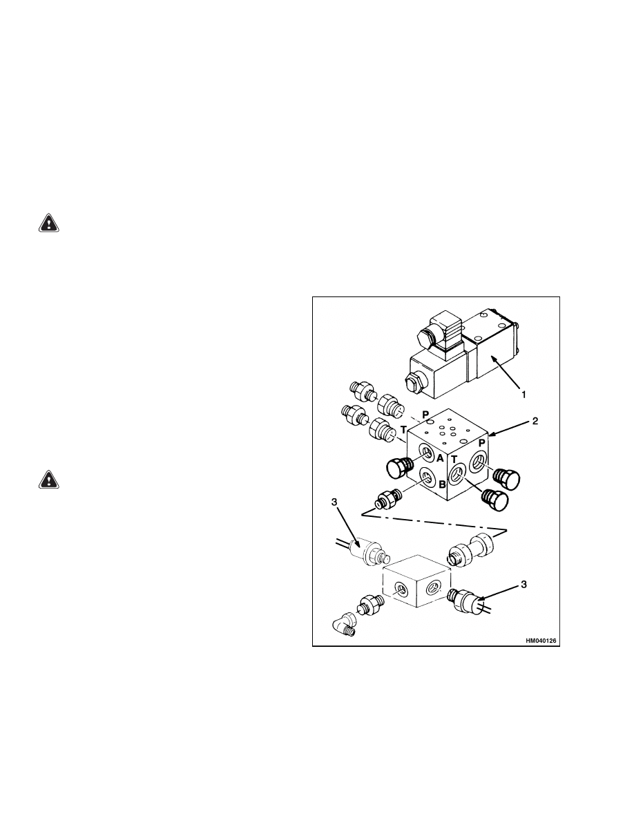
REPAIRS
Install new backup rings and O-rings and seals on
internal parts. See Figure 5. Install new O-rings at
each port. Install plugs.
INSTALL
1.
Install parking brake valve. Connect lines.
2.
Operate system, and check for leaks and correct
operation of parking brake system. Remove air
from brake system as described in Brake System
Air Removal.
1.
SOLENOID VALVE
2.
MANIFOLD
3.
PRESSURE
SWITCH
Figure 5. Parking Brake Solenoid Valve
6
1800 SRM 785
Parking Brake Caliper Repair
Parking Brake Caliper Repair
REMOVE
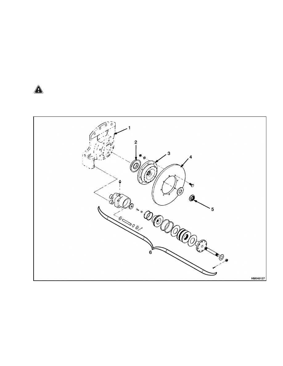
1.
Put blocks in front and back of tires so vehicle
cannot move. See Figure 6.
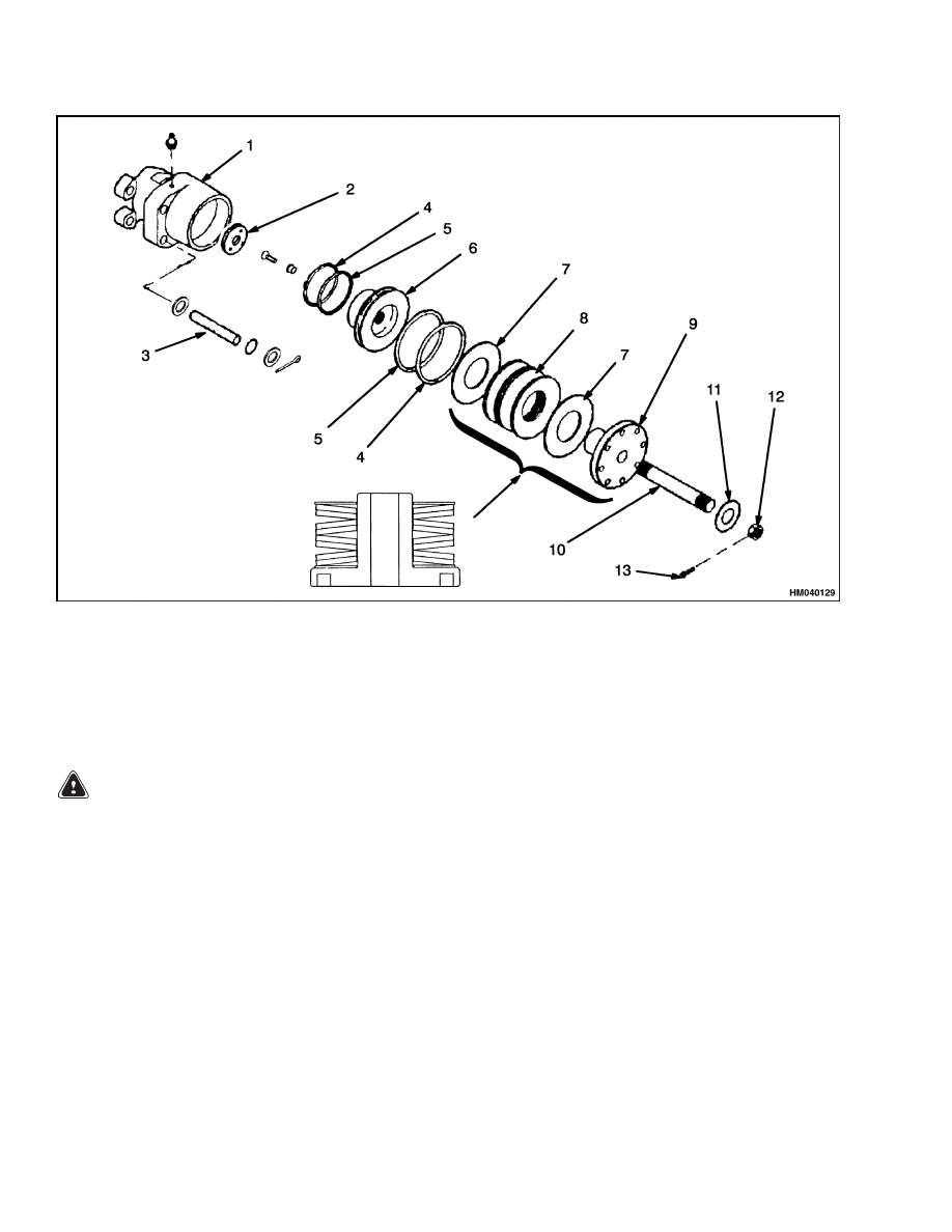
2.
Remove cotter pin and tighten nut to release
parking brake. See Figure 7.
WARNING
Before disconnecting any hydraulic lines, re-
lease pressure from the hydraulic circuit as fol-
lows:
• Shut off the engine and completely lower the
boom. Install blocks at the wheels to prevent
the vehicle from moving.
• Operate the brake pedal until the hydraulic
pressure is released.
3.
Release pressure from accumulator. Disconnect
hydraulic line at caliper. Put cap on open line.
1.
CALIPER MOUNT
2.
OIL SEAL
3.
ROTOR FLANGE
4.
ROTOR
5.
NUT AND WASHER
6.
CALIPER ASSEMBLY
Figure 6. Parking Brake Assembly
7
Parking Brake Caliper Repair
1800 SRM 785
1.
CALIPER HOUSING
2.
BRAKE LINING (2)
3.
ALIGNMENT PIN (2)
4.
BACKUP RING
5.
O-RING
6.
PISTON
7.
WASHER
8.
SPRING
9.
SPRING COVER
10. STUD
11. WASHER
12. NUT
13. COTTER PIN
Figure 7. Parking Brake Caliper
WARNING
Brake linings can contain dangerous fibers.
Breathing the dust from these linings can
be a cancer or lung disease hazard.
Do not
make dust!
Do not clean brake parts with
compressed air or by brushing. Use vacuum
equipment approved for brake dust or follow
the cleaning procedure in this section. When
calipers are removed, do not make dust.
Do not sand, grind, chisel, hammer, or change
linings in any way that will make dust. Any
changes to linings must be done in a restricted
area with special ventilation. Protective cloth-
ing and a respirator must be used.
4.
Remove pins that hold caliper to bracket. Re-
move caliper and brake linings.
DISASSEMBLE
1.
Remove nut from stud.
See Figure 7.
Care-
fully remove cover from caliper housing. Remove
washers and springs from housing.
2.
Pull piston from bore.
CLEAN
1.
Do not release brake lining dust from brake lin-
ings into air.
2.
Use a solvent approved for cleaning of brake
parts to wet the brake lining dust. Follow in-
structions and cautions of manufacturer for use
of the solvent. If a solvent spray is used, spray
at a distance so dust is not released into air.
8
1800 SRM 785
Parking Brake Caliper Repair
3.
When brake lining dust is wet, clean parts. Put
any cloth or towels in a plastic bag or an airtight
container while they are still wet. Put a DAN-
GEROUS FIBERS warning label on plastic bag
or airtight container.
4.
Any cleaning cloths that will be washed must be
cleaned so brake lining fibers are not released
into air.
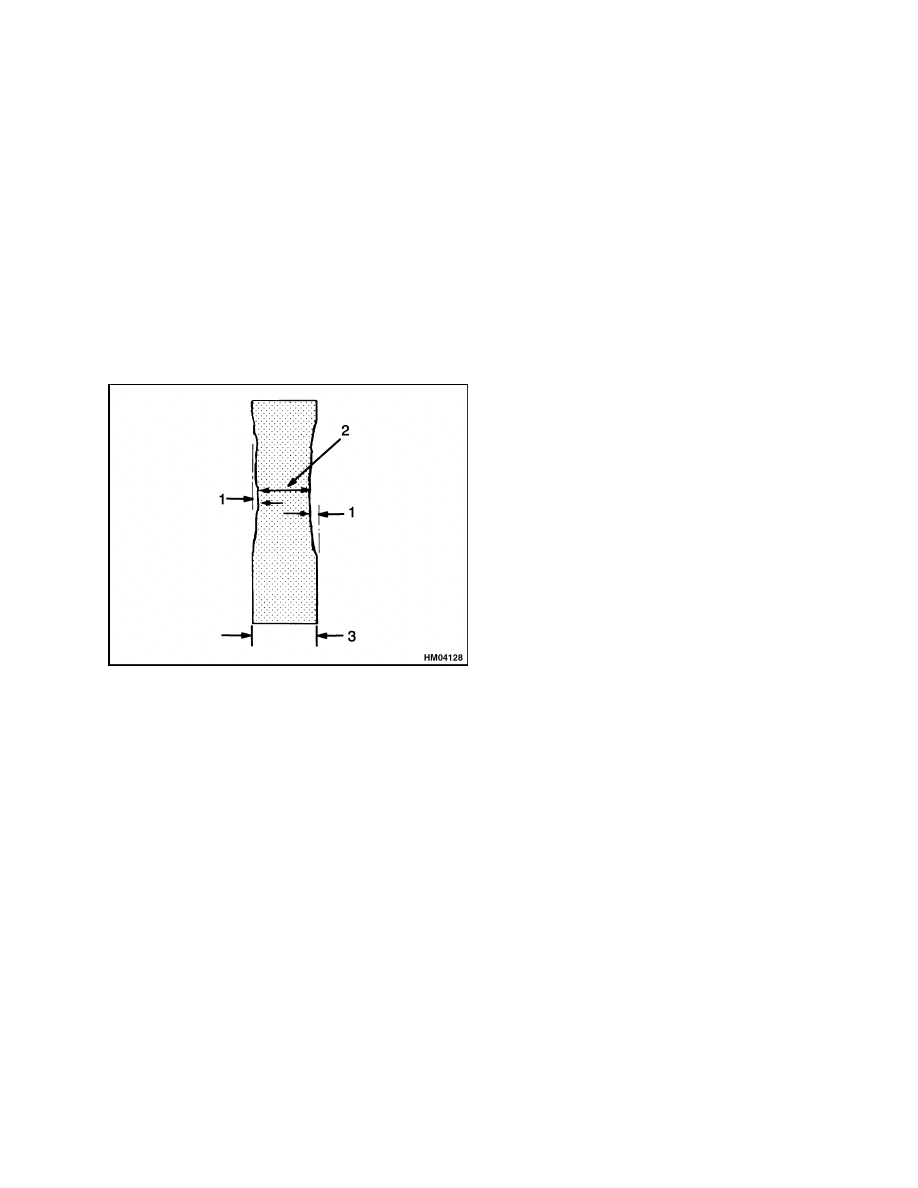
INSPECT
Inspect parts and bores for scratches. If there are
scratches or other damage, replace damaged parts.
Inspect rotor as shown in Figure 8.
1.
MAXIMUM ROTOR WEAR 1.5 mm (0.06 in.)
2.
MINIMUM ROTOR THICKNESS 17.0 mm
(0.67 in.)
3.
ROTOR THICKNESS 20.07 mm (0.79 in.)
Figure 8. Inspect Rotor for Parking Brake
Caliper
ASSEMBLE
1.
Lubricate piston with clean hydraulic oil. See
Figure 7. Install O-rings and backup rings on
piston. Install piston in housing.
2.
Install washers and spring assembly in housing.
Install spring cover in housing.
3.
Install washer and nut on stud. Tighten nut to
retract piston.
INSTALL AND ADJUST
1.
Install caliper on bracket.
Install alignment
pins, O-rings, and cotter pins. See Figure 6 and
Figure 7.
2.
Connect hydraulic line to caliper. Loosen nut.
See Figure 7.
3.
Remove air from brake system as described in
Brake System Air Removal. Check for leaks.
4.
Adjust brake linings as follows:
a. Put blocks in front and back of tires so vehicle
cannot move.
b. Start engine and release parking brake (ap-
ply hydraulic pressure). Check that caliper
moves freely on alignment pins.
c.
Slide caliper so one of the brake linings is
against the brake rotor. Measure clearance
between brake lining and rotor. If clearance
is more than 3.4 mm (0.13 in.), continue with
adjustment procedures.
d. Turn nut until it just touches spring cover.
Apply parking brake (release hydraulic pres-
sure).
e.
Turn spring cover clockwise (tighten) until
both linings touch rotor. Turn spring cover
counterclockwise 1-1/2 turns, then measure
clearance between lining and rotor.
Turn
spring cover as necessary to obtain correct
clearance of 2.2 mm (0.090 in.).
f.
Release parking brake. Loosen nut and in-
stall cotter pin.
9
Service Brake Assembly Repair
1800 SRM 785
Service Brake Assembly Repair
The service brake assemblies are a part of the hub of
the drive axle. Most repairs are seal replacement at
the hub and brake housing. Replace these seals any
time the hub is removed.
NOTE: See Service Brakes Wear Check for the pro-
cedures to check the friction discs for wear.
REMOVE
1.
Put blocks in front and back of steer tires so ve-
hicle cannot move. See Figure 3.
WARNING
Completely remove the air pressure from the
tires before removing the wheels from the ve-
hicle. Air pressure in the tires can cause the
tire and rim parts to explode causing serious
injury or death.
Always wear safety glasses.
2.
Remove drive wheel and hub as described in the
section for Drive Axle.
WARNING
Before disconnecting any hydraulic lines, re-
lease pressure from the hydraulic circuit as fol-
lows:
• Shut off the engine and completely lower the
boom. Install blocks at the wheels to prevent
the vehicle from moving.
• Operate the brake pedal until the hydraulic
pressure is released.
3.
Disconnect hydraulic line for piston and the two
hydraulic lines for cooling oil. Put caps on all
open lines and ports.
4.
Remove mount bolts and carefully slide brake as-
sembly off spindle.
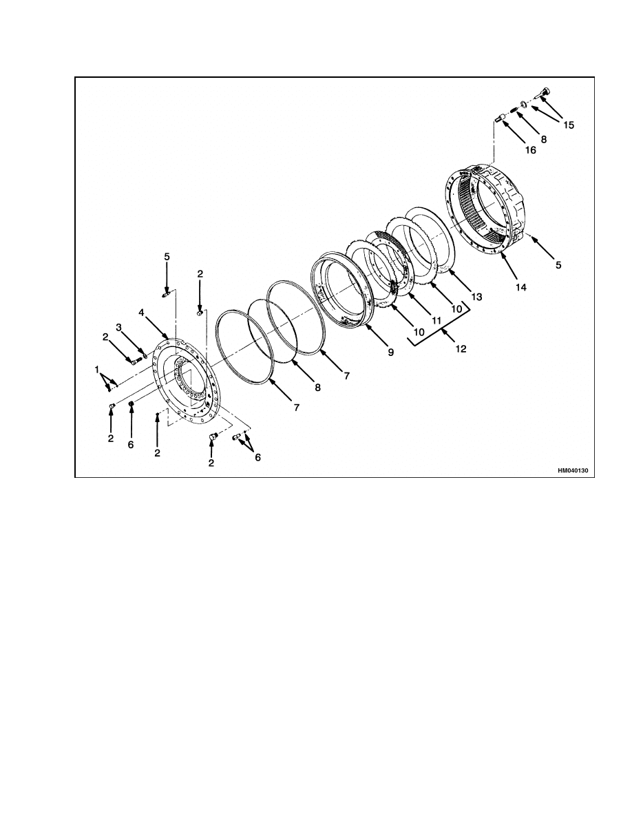
DISASSEMBLE
NOTE:
It is not necessary to disassemble brake as-
sembly to replace seals. Make sure all brake oper-
ating pressures are correct before replacing internal
parts of assembly. Incorrect operation is usually due
to other parts of the brake system.
If necessary, disassemble service brake assembly as
shown in Figure 9.
CLEAN
Make sure all loose material is cleaned out of hous-
ing.
INSPECT
Check all parts for wear or damage. Check lining
material on disc for wear that is not even and for
cracks or missing pieces. This inspection can indicate
the wear rate of the service brakes.
ASSEMBLE
CAUTION
Make sure to align all of the movable discs so
that they will fit on the hub correctly. Make
sure all the stationary discs are correctly in-
stalled in the housing. Damage to the discs will
occur during installation if the discs are not
correctly aligned.
Assemble service brake assembly as shown in Fig-
ure 9. Always use a new set of discs and use only new
seals and gaskets. Make sure to assemble discs so
stationary and rotating discs alternate in disc pack.
Make sure to tighten cover bolts in an alternate pat-
tern so cover fits on housing evenly.
INSTALL
Use new seals on spindle and between hub and as-
sembly housing. See Figure 3. Lubricate new seals
and seal surface with clean oil. Carefully install ser-
vice brake assembly on spindle. Carefully install hub
on spindle so splines of hub align with rotating discs.
Do NOT try to force hub into service brake housing.
Minor rotation can help splines and discs align cor-
rectly. Install remainder of drive axle parts as de-
scribed in the section for the Drive Axle. Install
brake lines as removed during Removal procedure.
Remove air from brake system as described in Brake
System Air Removal. Check for leaks.
10
1800 SRM 785
Service Brake Assembly Repair
1.
PLUG AND O-RING
2.
BOLT
3.
WASHER
4.
COVER
5.
BLEEDER SCREW
6.
FITTING
7.
SEAL
8.
SPRING
9.
PISTON
10. DISC, STATIONARY (1)
11. DISC, FRICTION (10)
12. DISC ASSEMBLY
13. SPACER
14. HOUSING
15. PLUG WITH ROD OR ROLL PIN
16. GUIDE
Figure 9. Service Brakes
11
Service Brakes Wear Check
1800 SRM 785
Brake System Air Removal
WARNING
Remove air from the brake system after each
installation or repair of hydraulic or brake sys-
tem components or hydraulic lines. The brakes
will not operate correctly with air in the system
and can cause injury or damage.
1.
Fill hydraulic tank to correct level.
Operate
engine to charge accumulator to maximum pres-
sure.
Keep engine operating at idle speed to
maintain pressure.
Push brake pedal several
times to fill brake system.
2.
Connect one end of hose to special fitting on
brake housing.
Put other end of hose in con-
tainer filled with clean hydraulic fluid.
3.
To remove air, loosen fitting and have a helper
operate brake pedal until no air is seen coming
out of hose in container. Tighten fitting after air
stops coming out and before disconnecting hose.
Connect hose at each of the following points:
a. Special fittings at each wheel brake assembly
b. Special fitting at the parking brake caliper
4.
Do Step 2 and Step 3 again after a wait of approx-
imately 2 hours to remove the last of the air.
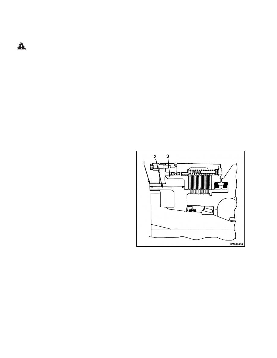
Service Brakes Wear Check
Check friction discs for wear by measuring stroke of
piston. See Figure 10.
1.
Run engine to load accumulator for brake system
to a normal level.
2.
Stop engine and apply parking brake. Put blocks
on both sides of drive tires to prevent movement
of truck.
3.
Remove outlet tube for brake cooling system. The
outlet fittings are at the front side of the drive
axle.
4.
Measure distance from edge of fitting to face of
piston.
This dimension will be just less than
127 mm (5.0 in.).
5.
Have helper push and hold down brake pedal to
activate service brakes.
6.
Check measurement between fitting and piston
again. The difference between the two measure-
ments is the stroke of the piston. The stroke
with new brake parts is 3.4 to 6.8 mm (0.134 to
0.269 in.). When the stroke is more than 13.3 mm
(0.525 in.), the friction discs need to be replaced.
7.
Check the other service brake assembly.
8.
Connect oil lines and remove air from brake sys-
tem.
1.
OUTLET FITTING
2.
STROKE
DISTANCE
3.
PISTON
Figure 10. Measure Service Brakes for Wear
12

1800 SRM 785
Troubleshooting
Oil Cooler Circuit Adjustment
Adjust the oil cooler circuit as follows (see Figure 4):
1.
Loosen relief valve on oil cooler solenoid. Install
a 250 bar (3626 psi) gauge at pressure port.
2.
Bypass one of the temperature switches to acti-
vate oil cooler solenoid. With engine at full throt-
tle, adjust relief pressure to 100 bar (1450 psi).
Troubleshooting
PROBLEM
POSSIBLE CAUSE
PROCEDURE OR ACTION
The brakes do not stop the
vehicle.
The linings are worn or damaged.
Replace brake linings.
There is not enough hydraulic pres-
sure in the system.
Check brake system pressure.
The brake lines have a restriction.
Check and replace brake lines.
The accumulator is damaged.
Install new accumulator.
The brakes apply slowly.
There is not enough hydraulic pres-
sure in the system.
Check brake system pressure.
The brake line(s) have a leak or re-
striction.
Check and replace brake lines.
Brake pedal(s) goes to the
floor.
There is air in the brake system.
Remove air from brake system.
There is a leak(s) in a brake line.
Check and replace brake lines.
The service brakes do not op-
erate equally.
The linings are worn or damaged.
Replace brake linings.
The brake line(s) have a restriction.
Check and replace brake lines.
The brake(s) does not re-
lease.
The brake linings are damaged.
Replace brake linings.
A brake line has a restriction.
Check and replace brake lines.
The parking brake is applied.
Check operation of parking brake.
13

Troubleshooting
1800 SRM 785
PROBLEM
POSSIBLE CAUSE
PROCEDURE OR ACTION
Service brakes do not oper-
ate when the engine is not
running.
There is no charge in the accumula-
tor.
Check oil supply to brake pedal valve.
Hydraulic lines for the accumulator
circuit leak or have restrictions.
Check and replace brake lines.
The parking brake does not
release.
The hydraulic pressure is too low.
Check oil supply to brake pedal valve.
There is a leak(s) in the hydraulic
lines.
Check and replace brake lines.
The parking brake valve is damaged.
Install new valve.
The parking brake caliper is dam-
aged.
Repair or replace brake caliper.
The parking brake will not
apply.
The springs in the brake caliper are
damaged.
Install new springs.
The brake caliper is not adjusted cor-
rectly.
Check and adjust caliper.
The brake linings are worn or dam-
aged.
Replace brake linings.
The brake rotor is worn or damaged.
Repair or replace brake rotor.
Accumulator fails to start
charging.
The relief valve in the brake pedal
valve does not work correctly.
Check and repair relief valve.
The line to the accumulator has a re-
striction.
Check and replace brake lines.
14


TECHNICAL PUBLICATIONS
1800 SRM 785
11/03 (1/00) Printed in United Kingdom
Document Outline
- toc
- Brake System YardMaster®
- Safety Precautions Maintenance and Repair
- General
- Description and Operation
- Pressure Switch Replacement
- Accumulator Replacement
- Brake Pedal Valves Repair
- Parking Brake Valve Repair
- Parking Brake Caliper Repair
- Service Brake Assembly Repair
- Brake System Air Removal
- Service Brakes Wear Check
- Oil Cooler Circuit Adjustment
- Troubleshooting
Wyszukiwarka
Podobne podstrony:
1452929 2200SRM0679 (11 2003) UK EN
1494141 1800SRM0937 (12 2003) UK EN
897987 1800SRM0659 (09 2003) UK EN
899648 2240SRM0001 (11 2003) UK EN
1470230 1600SRM0786 (11 2003) UK EN
897109 1800SRM0327 (09 2003) UK EN
1452929 2200SRM0679 (11 2003) UK EN
897653 1800SRM0566 (04 2005) UK EN
1494953 1400SRM0944 (09 2003) UK EN
1466205 2100SRM0735 (11 2004) UK EN
897394 1900SRM0453 (09 2003) UK EN
1494145 8000SRM0940 (10 2003) UK EN
więcej podobnych podstron