INDUSTRIAL BATTERY
ALL ELECTRIC LIFT TRUCKS
PART NO. 899648
2240 SRM 1

SAFETY PRECAUTIONS
MAINTENANCE AND REPAIR
• When lifting parts or assemblies, make sure all slings, chains, or cables are correctly
fastened, and that the load being lifted is balanced. Make sure the crane, cables, and
chains have the capacity to support the weight of the load.
• Do not lift heavy parts by hand, use a lifting mechanism.
• Wear safety glasses.
• DISCONNECT THE BATTERY CONNECTOR before doing any maintenance or repair
on electric lift trucks.
• Disconnect the battery ground cable on internal combustion lift trucks.
• Always use correct blocks to prevent the unit from rolling or falling. See HOW TO PUT
THE LIFT TRUCK ON BLOCKS in the Operating Manual or the Periodic Mainte-
nance section.
• Keep the unit clean and the working area clean and orderly.
• Use the correct tools for the job.
• Keep the tools clean and in good condition.
• Always use HYSTER APPROVED parts when making repairs. Replacement parts
must meet or exceed the specifications of the original equipment manufacturer.
• Make sure all nuts, bolts, snap rings, and other fastening devices are removed before
using force to remove parts.
• Always fasten a DO NOT OPERATE tag to the controls of the unit when making repairs,
or if the unit needs repairs.
• Be sure to follow the WARNING and CAUTION notes in the instructions.
• Gasoline, Liquid Petroleum Gas (LPG), Compressed Natural Gas (CNG), and Diesel fuel
are flammable. Be sure to follow the necessary safety precautions when handling these
fuels and when working on these fuel systems.
• Batteries generate flammable gas when they are being charged. Keep fire and sparks
away from the area. Make sure the area is well ventilated.
NOTE:
The following symbols and words indicate safety information in this
manual:
WARNING
Indicates a condition that can cause immediate death or injury!
CAUTION
Indicates a condition that can cause property damage!

Industrial Battery
Table of Contents
TABLE OF CONTENTS
General ...............................................................................................................................................................
Lead-Acid Batteries ...........................................................................................................................................
Specific Gravity ..................................................................................................................................................
Chemical Reaction in a Cell ..............................................................................................................................
Electrical Terms .................................................................................................................................................
Battery Selection................................................................................................................................................
Battery Voltage ..................................................................................................................................................
Battery as a Counterweight ..............................................................................................................................
Battery Ratings..................................................................................................................................................
Kilowatt-Hours ..............................................................................................................................................
Battery Maintenance .........................................................................................................................................
Safety Procedures ..........................................................................................................................................
Maintenance Records ....................................................................................................................................
New Battery ...................................................................................................................................................
Cleaning Battery ...........................................................................................................................................
Adding Water to Battery ...............................................................................................................................
Hydrometer ....................................................................................................................................................
Battery Temperature .....................................................................................................................................
Charging Battery ...........................................................................................................................................
Types of Battery Charges..........................................................................................................................
Methods of Charging .................................................................................................................................
Troubleshooting Charger ..........................................................................................................................
Knowing When Battery Is Fully Charged ...............................................................................................
Where to Charge Batteries............................................................................................................................
Equipment Needed ....................................................................................................................................
Battery Connectors........................................................................................................................................
Battery Care ..................................................................................................................................................
This section is for the following models:
All Electric Lift Trucks
©2004 HYSTER COMPANY
i

"THE
QUALITY
KEEPERS"
HYSTER
APPROVED
PARTS
2240 SRM 1
Lead-Acid Batteries
General
This section describes how to select and do the main-
tenance for large batteries used in electric lift trucks.
This information is for service personnel that must
do the maintenance on large lead-acid batteries. Bat-
tery repair requires special training and equipment.
Do not try to repair a battery unless you have the cor-
rect tools, equipment, and experience. Most battery
repairs are done by a special repair service. Some
batteries have a nameplate attached to the face of the
battery cover. This nameplate communicates specific
information about the battery including the name of
the battery manufacturer, battery type, serial num-
ber, nominal voltage, capacity in amperes at the five
hour rate, and service mass (with ballast if used to
compensate for lack of battery mass).
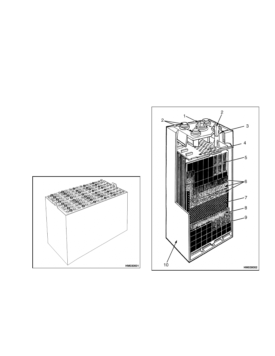
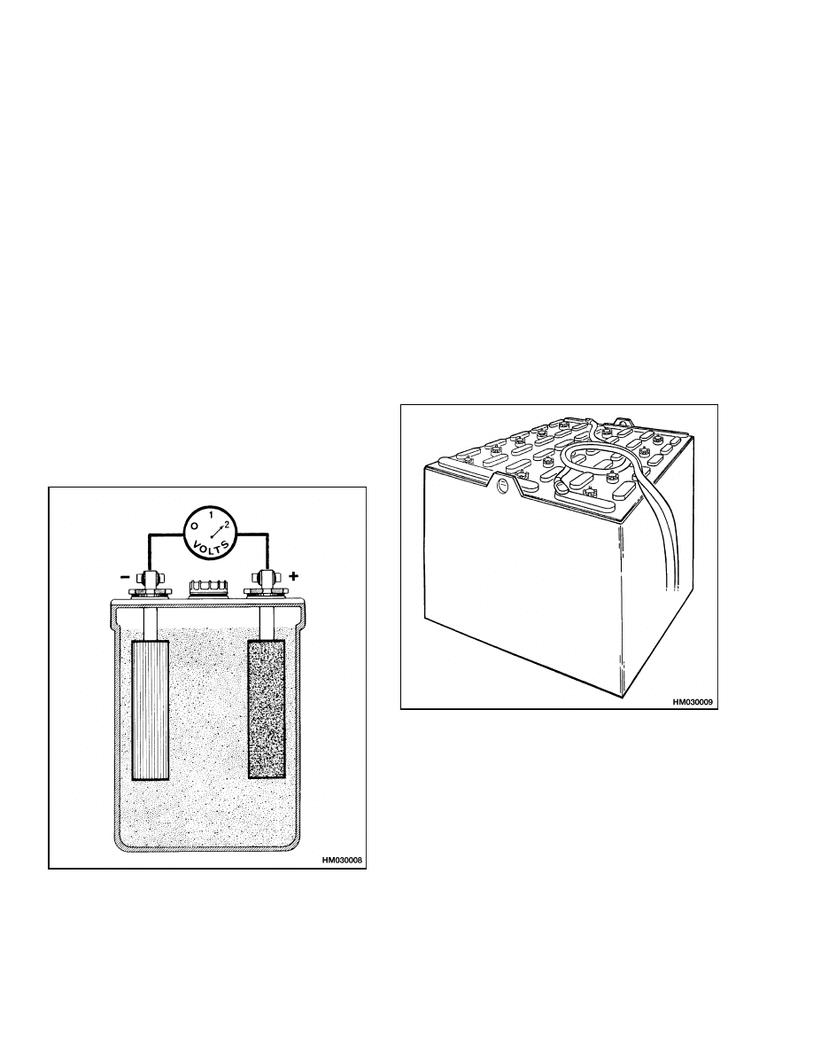
Lead-Acid Batteries
A lead-acid battery converts chemical energy into
electrical energy. See Figure 1. Chemical changes
within the battery give the electrical energy. When
the chemical reaction has occurred so the battery
will not give its rated voltage and current, the bat-
tery is discharged. A reverse chemical action must
occur so the battery can be used again. The batteries
described in this section can be charged again by an
electric voltage and current from an outside source
so there is a reverse chemical action. The lead-acid
chemicals store the electric energy until the electric
energy is needed to operate an electric device.
Figure 1. Lead-Acid Industrial Battery
A lead-acid battery is made from several lead-acid
batteries called cells.
Each cell has positive and
negative plates with dielectric spacers between each
plate.
All of the plates are within a solution of
electrolyte. See Figure 2.
1.
VENT AND FILL
CAP
2.
POST
3.
POST SEAL
4.
PLATE
PROTECTOR
(SHIELD)
5.
POSITIVE PLATE
6.
EXPANSION MATS
7.
RETAINER
8.
SEPARATOR
9.
NEGATIVE PLATE
10. BATTERY JAR
Figure 2. Battery Cell
1
Chemical Reaction in a Cell
2240 SRM 1
Specific Gravity
The strength of the electrolyte is measured in points of specific gravity. For example, a solution of sulfuric
acid has a specific gravity of 1.835. Water has a specific gravity of 1.000. Electrolyte is 27 percent acid and 73
percent water and has a specific gravity of 1.275.
Chemical Reaction in a Cell
WARNING
NEVER pour water into concentrated acid.
The quick generation of heat can cause the
acid to boil and splash out of the container.
ALWAYS pour concentrated acid into water
when making a dilute solution of acid.
In a fully charged cell, the electrolyte has a specific
gravity of 1.270 to 1.130. NEVER discharge a battery
below a specific gravity of 1.130. The battery can
have permanent damage if discharged below 1.130.
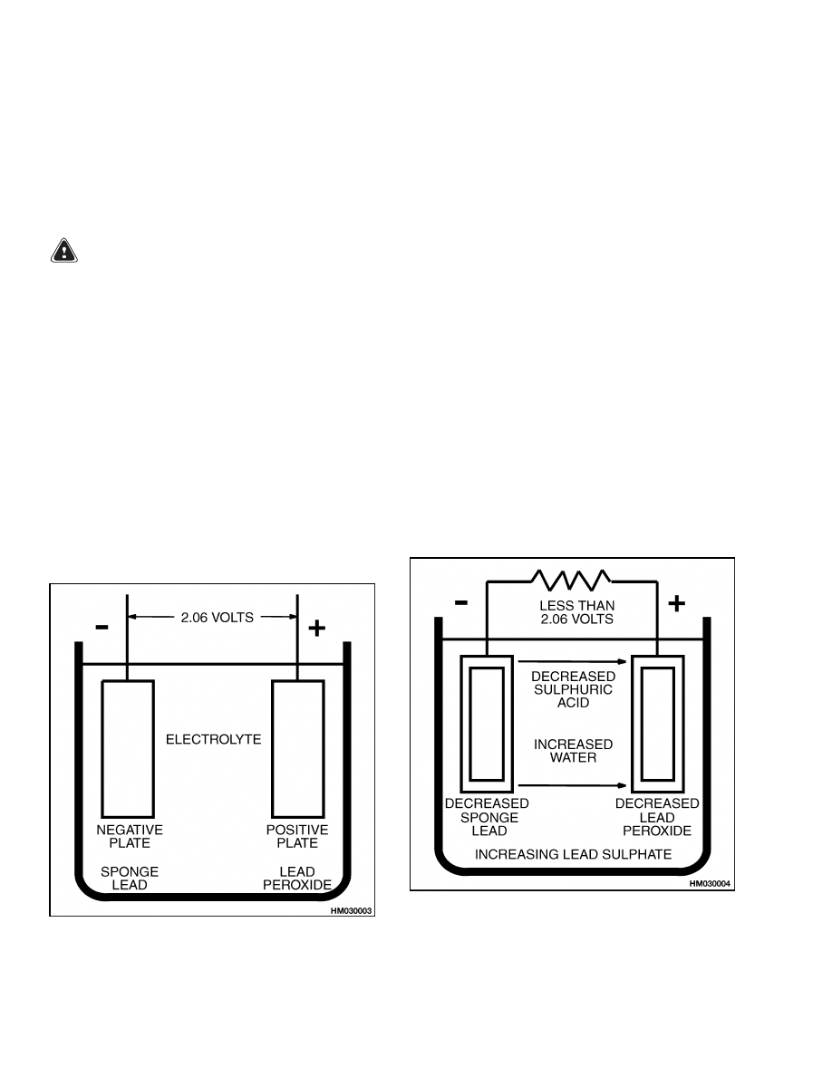
The cell generates a voltage (potential difference)
when two different types of metal are in the elec-
trolyte. The two metals in a lead-acid cell are lead
peroxide (PbO
3
) for positive plates, and sponge lead
(Pb) for negative plates.
See Figure 3.
A poten-
tial difference of approximately 2 volts per cell is
generated. The potential difference does not vary
according to the size of the cell.
Figure 3. Fully Charged Cell
During the discharge of the cell, lead peroxide and
sponge lead mix with sulfuric acid to make lead sul-
fate (PbSO
4
) on both plates. See Figure 4. This ac-
tion decreases the voltage in the cell. When the sul-
furic acid is removed from the electrolyte, the specific
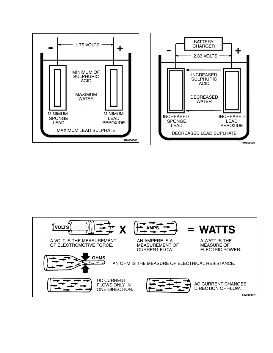
gravity of the electrolyte decreases. See Figure 5.
The potential difference of a discharged cell is ap-
proximately 1.75 volts.
When a direct current is applied to a discharged cell,
the lead sulfate is changed into lead and sulfuric acid.
The lead goes to the positive plate and stays as lead
and to the negative plate and stays as lead peroxide.
See Figure 6. The concentration of sulfuric acid in
the electrolyte increases. The specific gravity of the
electrolyte increases as the concentration of sulfuric
acid increases. In a fully charged cell, the positive
plate again contains the lead peroxide and the nega-
tive plate contains the sponge lead.
Figure 4. Discharging Cell
2
2240 SRM 1
Electrical Terms
Figure 5. Discharged Cell
Figure 6. Charging Cell
Electrical Terms
Voltage is an electromotive force (EMF) (also called
"potential difference") caused by the difference in
electric charge between two points. See Figure 7.
Ampere is a measurement of electric current.
Watt is a measure of electric power. The number
of watts is equal to the number of volts multiplied
by the number of amperes. A kilowatt-hour is 1000
watts of electric power used in 1 hour.
Ohms is the measurement of electrical resistance.
Polarity. In a battery, the electric current is shown
to flow from the positive terminal to the negative ter-
minal.
Figure 7. Electrical Terms
3
Battery Selection
2240 SRM 1
Direct Current (DC). When the voltage between
the two terminals is always the same polarity, the
current flow and voltage are called Direct Current.
Alternating Current (AC). When the polarity of
voltage between two terminals is changing between
positive and negative at a quick and constant rate,
the voltage is called Alternating Current.
Battery Selection
The battery needed to operate a period of 8 hours de-
pends on many conditions. Operations that require
the lift truck to go up ramps or require the use of ad-
ditional attachments increase the use of power from
the battery. Some work conditions require that more
than one battery must be used during a work period.
The number of 8-hour work periods per day is nor-
mally equal to the number of batteries needed. For
example, for three work periods, you need three bat-
teries. The capacity of the battery you need is found
as follows:
• The size of the lift truck and the attachments.
• The type of work. Heavy-duty operation or normal
operation for one 8-hour work period.
Figure 8. Cell Voltage
Lift trucks are available in various voltage ranges.
See Figure 8. The small "walkie" lift trucks are nor-
mally 12 or 24 volts. The larger sit-down rider lift
trucks are normally 24, 36, 48, 72, or 80 volts. The
number of cells in a lead-acid battery gives the bat-
tery voltage. See Figure 9. A fully charged cell has
a potential difference of approximately 2 volts. See
Figure 8. This potential difference does not change
with size of the cell.
Figure 9. Multicell Battery for Electric Lift
Truck
4

2240 SRM 1
Battery Ratings
Battery Voltage
The battery voltage you need is found as follows:
• Will your lift truck operate on more than one volt-
age?
• If you have more than one lift truck in operation,
do the battery voltages need to be the same?
To reach the necessary battery voltage, the cells are
connected in series. For example:
24 volts = 12-cell battery
36 volts = 18-cell battery
48 volts = 24-cell battery
72 volts = 36-cell battery
80 volts = 40-cell battery
Battery as a Counterweight
On electric lift trucks that use the battery as part
of the counterweight, the battery is part of the ca-
pacity of the lift truck to lift loads. The minimum
weight of the battery is shown on the nameplate. If
the battery is not the minimum weight, the capacity
of the lift truck is reduced. If the battery used in the
lift truck is less than the size of the battery compart-
ment, blocks and spacers must be installed to hold
the battery in position.
Battery Ratings
The ratings of batteries are measured in ampere-
hours and kilowatt-hours at a constant rate of dis-
charge. A rating of 6 hours is the standard. Ampere-
hours is the measurement of battery capacity. To
calculate ampere-hours, multiply amperes by hours.
See Table 1. For example, 5 amperes times 5 hours
is 25 ampere-hours. You cannot change the potential
difference of a cell. You can increase the ampere-hour
rating by increasing the number of plates in a cell,
or by installation of larger plates. The constant rate
of discharging can be compared to a measurement of
the battery capacity and ampere-hours. For exam-
ple, a battery with a rating of 600 ampere-hours dur-
ing a work period of 6 hours will generate 100 am-
peres per hour for 6 hours. The same battery cannot
generate 300 amperes for 2 hours. The heat gener-
ated within the battery will damage the battery.
Table 1. Battery Capacity Terms
Amperes × Hours = Ampere-Hours
600 Ampere Hours = 100 Amperes for 6 Hours
Volts × Amperes × Hours/1000 = Kilowatt-Hours
(KWH)
KILOWATT-HOURS
A kilowatt is 1000 watts. A watt is a measure of
electric power. The capacity in kilowatt-hours is the
total power generated by the battery. Watt-hours
are measured by multiplying the voltage by ampere-
hours. To measure the kilowatt-hours, divide the
watt-hours by 1000.
volts × amperes × hours
1000
= kilowatt-hours or kWh
To calculate the kilowatt-hours for a battery that has
a rating of 600 ampere-hours and a 48-volt system,
use this formula:
48 volts × 600 amperes × hours
1000
= 28.8 kWh
The watt-hours can be converted to kilowatt-hours
to indicate the battery needed for the operation. Al-
ways select the correct type of battery. Remember,
a battery that has a rating of 300 ampere-hours will
not do the same job as a battery that has a rating of
600 ampere-hours. Do not permit the specific gravity
to go below the limits shown in the manual.
5

Battery Maintenance
2240 SRM 1
Battery Maintenance
Battery maintenance must include the following
items:
• A good battery charger
• A clean battery
• Keep the electrolyte at the correct level
• Keep a record of the battery
SAFETY PROCEDURES
1.
Wear a rubber apron, gloves, boots, and goggles
or a face shield when doing maintenance on bat-
teries.
2.
Batteries generate hydrogen gas when they are
being charged. Keeps open fire away from bat-
teries. Do not check the electrolyte level with a
match or a lighter. Do not smoke and do not cre-
ate sparks.
3.
Lift batteries correctly with a crane or equipment
designed for the job. Always use a spreader bar
designed and adjusted for the battery. Move bat-
teries with a lift truck or a conveyor or rollers de-
signed for that purpose. If the battery does not
have a cover, a rubber mat or insulating material
must be put over the top of the battery to prevent
a short circuit with other equipment. Make sure
the lifting equipment has enough capacity for the
job. Do not use chain or wire rope slings.
4.
Never put metal materials or tools on a battery.
5.
Disconnect battery from lift truck before doing
maintenance or repairs.
6.
When maintenance on the battery or the battery
charger is required, disconnect both the AC and
DC power. If the battery connectors must be re-
placed, make sure the positive and negative ter-
minals and cables are kept separate and insu-
lated from each other. Even a momentary short
circuit can cause an explosion and damage the
battery.
7.
Keep water readily available to flush spilled elec-
trolyte. Electrolyte in the eyes must be flushed
with water immediately, and then quickly get
medical attention.
Special showers and eye
wash systems are required in areas where bat-
tery maintenance is done.
8.
If electrolyte is spilled on a work surface or the
floor, flush area with water, use a solution of soda
(sodium bicarbonate) to make the acid neutral.
9.
Only trained persons are permitted to do main-
tenance on batteries and battery chargers. Make
sure the regulations by government safety agen-
cies, government insurers, private insurers, and
private organizations are followed when doing
maintenance on batteries.
MAINTENANCE RECORDS
NOTE:
Follow the same sequence when you record
the cell number. Always begin the record with a pos-
itive cell. Follow a sequence so the last cell is always
the cell for the negative cable.
Record the beginning ampere reading of the charger
each time the battery is charged. Any difference in
the daily ampere reading can indicate a problem with
the battery or the charger.
NEW BATTERY
CAUTION
Always use a spreader bar and slings that lift
vertically on the lifting eyes of the battery. DO
NOT use a chain or sling without a spreader
bar or you will damage the battery case.
Use the correct blocks or spacers to hold the
battery in position in the lift truck. Make sure
the battery compartment is clean and dry. All
vent caps must be in position when the battery
is in service. If the vent caps are not installed,
the electrolyte will leak, causing corrosion on
the battery case and in the battery compart-
ment.
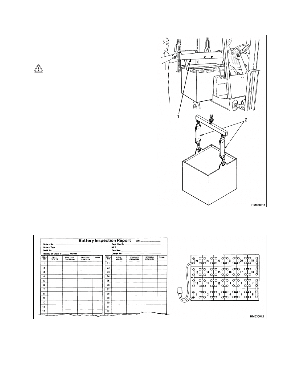
Inspect a new battery for damage. Make sure the
electrolyte in each of the cells is at the correct level.
Charge the battery for 6 hours or until the specific
gravity is correct. Make sure the battery is correctly
installed in the lift truck. Use a spreader bar with
slings designed for the battery to lift and move the
battery. See Figure 10.
Always complete the Battery Inspection Report and
the Daily Battery Report. See Figure 11 and Fig-
ure 12.
6
2240 SRM 1
Battery Maintenance
CLEANING BATTERY
Keep the battery compartment clean and dry. Use a
clean cloth to wash the battery with water. Dry with
compressed air.
CAUTION
Do not clean the battery with steam or hot wa-
ter. Do not use a high-pressure hose.
Remove any electrolyte from the battery compart-
ment to prevent corrosion. If there is electrolyte on
the top of the battery, apply a solution of bicarbonate
of soda. Mix a solution containing 0.5 kg of soda for
every 4 liters of water. Apply the solution, then flush
the solution from the battery with clean water. Wash
the battery and battery compartment as needed, but
within a 6 month period as the maximum time.
NOTE: If the top of the battery is wet from elec-
trolyte, check that the electrolyte level is not too high
or the battery charger is not operating correctly.
1.
INSULATED
SPREADER BAR
2.
INSULATED
STRAPS
Figure 10. Change the Battery
Figure 11. Battery Inspection Report
7
Battery Maintenance
2240 SRM 1
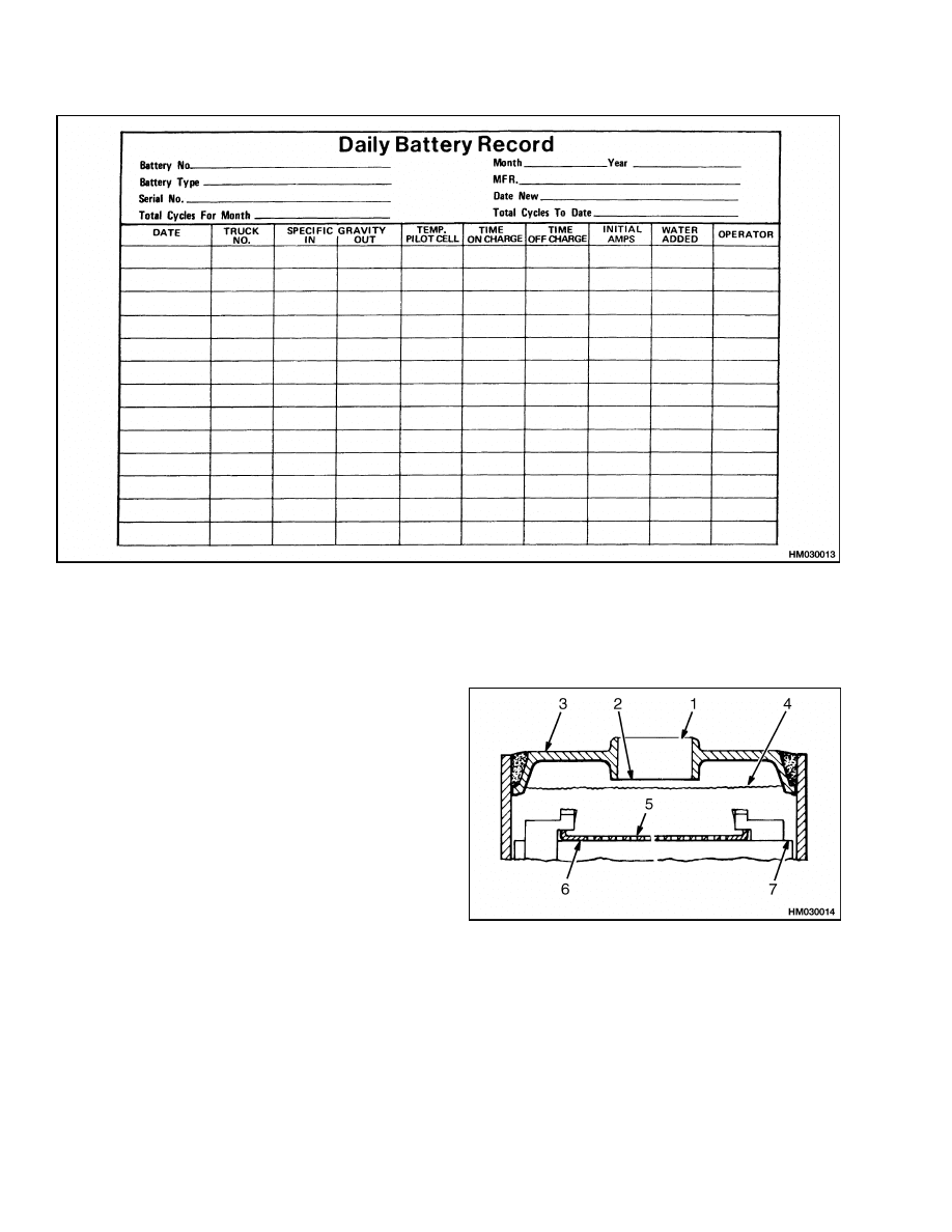
Figure 12. Daily Battery Report
ADDING WATER TO BATTERY
NOTE:
Some batteries have sealed cells. These bat-
teries do not need water added to the electrolyte.
Some water is lost from the electrolyte of each cell
during the charge and discharge cycle when the bat-
tery is in service. Check the electrolyte level daily.
Some service persons check some of the cells each day
so all cells are checked each week. If the level of the
electrolyte goes below the level of the top of the sep-
arators for the plates, the cell can be damaged.
KEEPING THE ELECTROLYTE LEVEL WITHIN
THE CORRECT LIMITS IS THE MOST IMPOR-
TANT ITEM OF BATTERY MAINTENANCE.
See the instructions from the manufacturer of your
battery for the operating level of the electrolyte. Al-
ways use distilled water. If you add distilled water,
wait 5 minutes before measuring the specific grav-
ity with a hydrometer. DO NOT add water to a cell
before or during the charging cycle; water must be
added after the charging cycle. If water is added be-
fore the charging cycle, the electrolyte level may rise,
which will cause electrolyte to be forced out of the
vent plugs. The electrolyte can flow out of the cell
through the fill hole. The correct electrolyte level is
shown in Figure 13.
1.
FILL TUBE
2.
BOTTOM OF FILL
TUBE
3.
CELL COVER
4.
MAXIMUM LEVEL
OF ELECTROLYTE
5.
MINIMUM LEVEL
OF ELECTROLYTE
6.
PLATE
PROTECTOR
7.
TOP OF
SEPARATORS
Figure 13. Electrolyte Level
8
2240 SRM 1
Battery Maintenance
HYDROMETER
NOTE:
Some batteries have sealed cells. The specific
gravity of the electrolyte cannot be checked on these
batteries.
Use a hydrometer to measure the specific gravity of
the battery. Make sure there is enough electrolyte in
the battery cells. See Adding Water to Battery in this
section. A high level or low level of the electrolyte can
change the specific gravity measurement. When the
electrolyte level is low, the percent of sulfuric acid in
the electrolyte increases. When the electrolyte level
decreases by 3 mm (1/8 in.), the specific gravity mea-
surement can increase by 3 to 5 points.
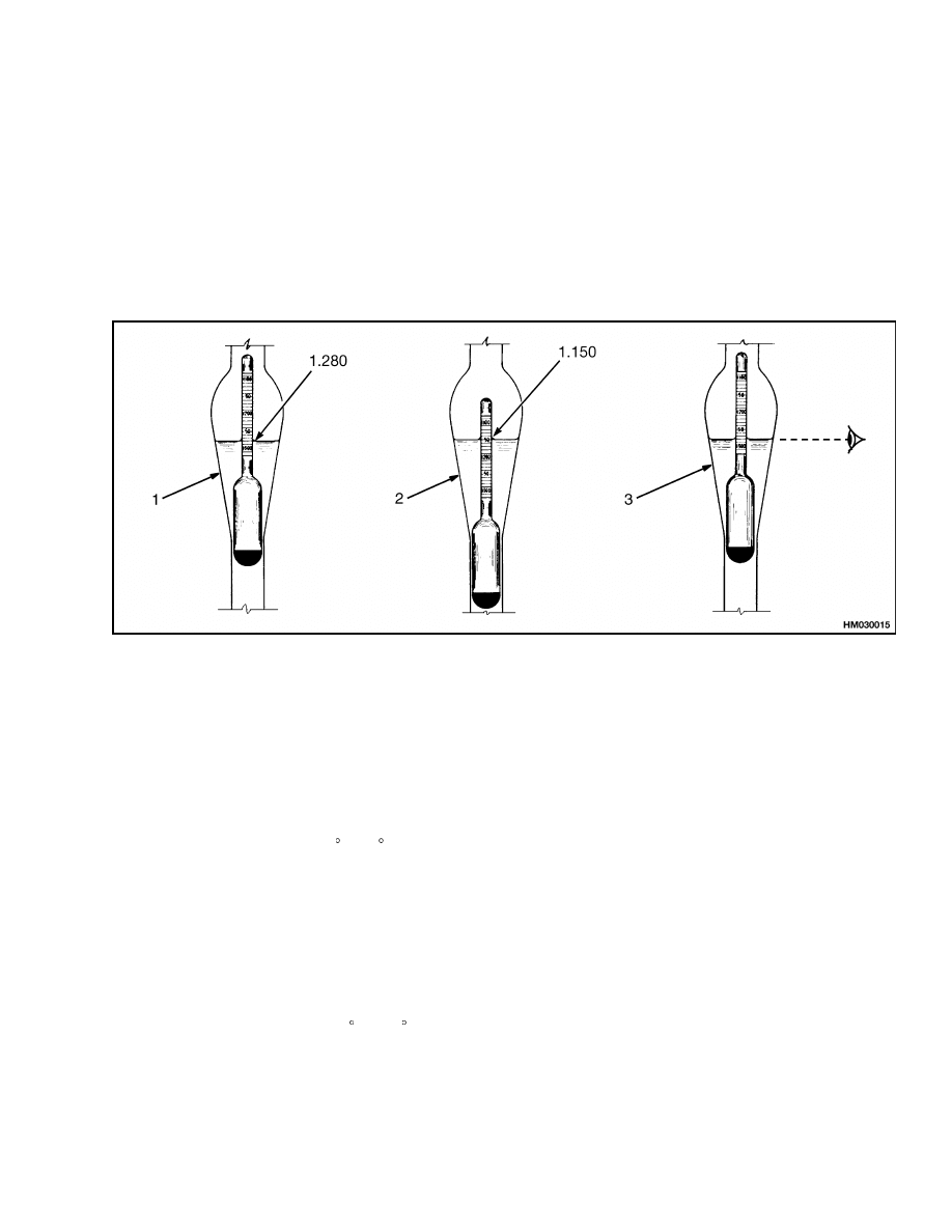
When you use the hydrometer, make sure there is
enough liquid in the barrel to let the float move freely.
The float must not touch the side, top, or bottom of
the barrel. See Figure 14 for the correct method of
reading the hydrometer.
1.
HIGH FLOAT MEANS HIGH SPECIFIC GRAVITY.
2.
LOW FLOAT MEANS LOW SPECIFIC GRAVITY.
3.
CORRECT METHOD OF READING HYDROMETER: EYE LEVEL EVEN WITH SURFACE OF
ELECTROLYTE.
Figure 14. Reading Hydrometer
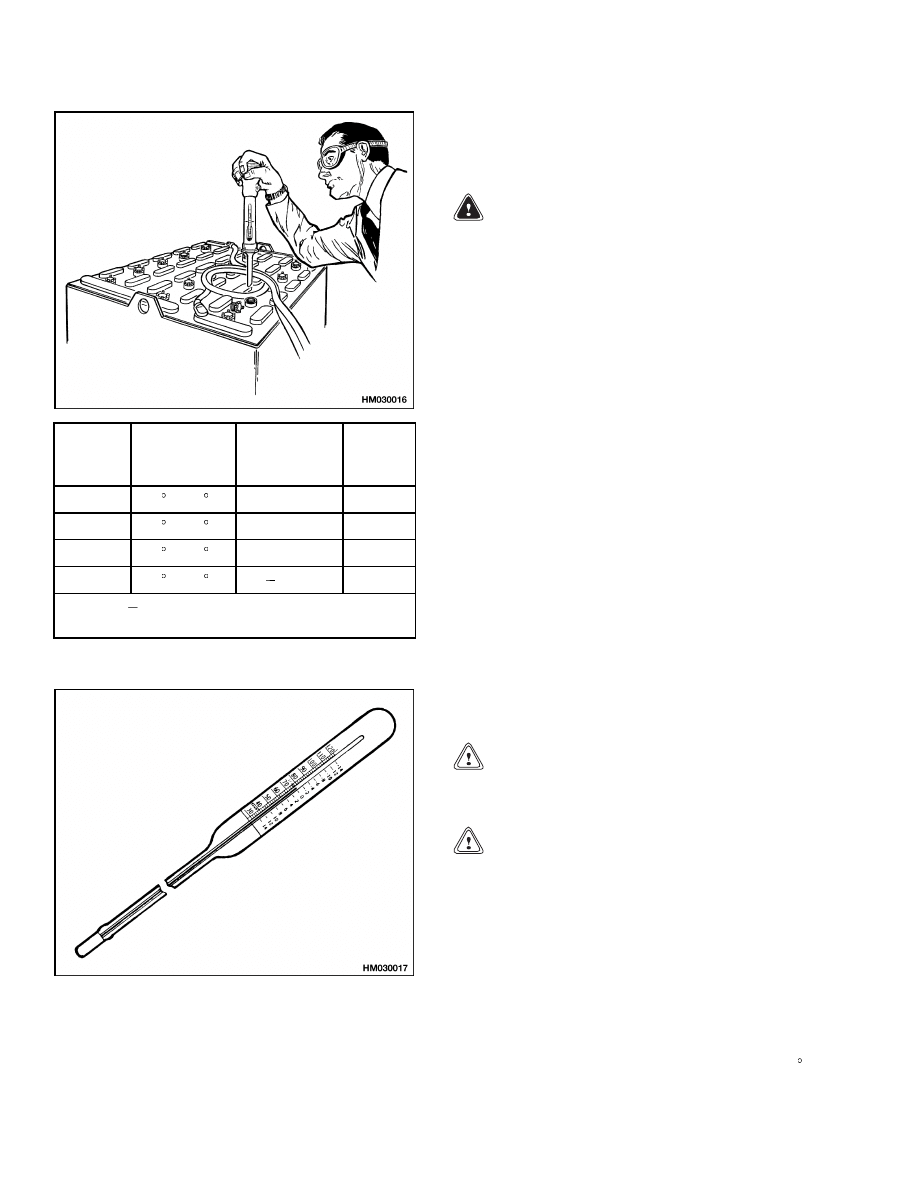
BATTERY TEMPERATURE
The temperature of the electrolyte will change the
reading of the specific gravity. When the tempera-
ture increases approximately 6 C (10 F), the specific
gravity will decrease by 0.003 point. See Figure 15
for making specific gravity corrections. If the hy-
drometer you are using does not have a temperature
correction, you will have to use a thermometer. Spe-
cial battery thermometers are available that will in-
dicate the correction factor directly and add or sub-
tract the correct number of points. See Figure 16.
NEVER charge a battery at a rate that will raise the
electrolyte temperature above 49 C (120 F). NEVER
let a battery stay discharged for long periods. A tem-
perature above this amount will damage the battery.
The cells in the center of the battery are normally at
the highest temperature. If the battery temperature
is too hot, make sure the ventilation of the battery
is increased and make sure the charge or discharge
rate is not too high. A recommendation for a battery
in service is 8 hours of use (discharge), followed by 8
hours of cooling, followed by 8 hours of charging.
To charge the battery, a direct current must pass
through the cells in the opposite direction to the dis-
charging current. The ampere-hours must be equal
to the discharging ampere-hours plus the energy lost
as heat. This additional amount of charge will vary
according to the battery and the temperature, but the
average additional charge is 12 percent. When the
battery is nearly charged, the final charging must be
at a low rate. A charging rate that is too high will
cause heating in the battery and a high loss of wa-
ter from the electrolyte. The charging of the battery
must be done correctly, or the service life of the bat-
tery will be decreased.
9
Battery Maintenance
2240 SRM 1
Specific
Gravity
Reading
Electrolyte
Temp.
Correction
Points
Correct
Value
1.210
31 C (88 F)
+0.003
1.213
1.210
27 C (81 F)
+0.001
1.211
1.210
25 C (77 F)
0.000
1.210
1.210
18 C (64 F)
0.004
1.206
+0.001 or
0.001 for each 2 degrees C from the
25-degree base value.
Figure 15. Specific Gravity Check
Figure 16. Battery Thermometer
CHARGING BATTERY
NOTE: There can be one of two types of batteries.
One type has removable cell caps. The other type
has sealed cells. The sealed batteries require a dif-
ferent charger. The electrolyte level or specific grav-
ity cannot be checked, and water cannot be added to
the electrolyte of these sealed batteries.
WARNING
The acid in the electrolyte can cause injury.
If electrolyte is spilled, use water to flush the
area. Make the acid neutral with a solution of
sodium bicarbonate.
Batteries generate explosive fumes when they
are being charged. Keep fire, sparks, and burn-
ing material away from the battery charger
area. Prevent sparks from the battery connec-
tors.
Charge batteries only in the special area for
charging batteries.
When charging the bat-
teries, keep the vent caps clean. The battery
charger area must have ventilation so that
explosive fumes are removed. Open the hood
over the battery or remove the cover if the
battery has a cover.
Disconnect the battery when doing cleaning
and maintenance.
If the lift truck has been operated with a low
battery, check the contactors for welded con-
tacts before a charged battery is connected.
The circuit will not reset and lift truck oper-
ation cannot be controlled if the contacts are
welded. To check the contacts, see the section
EV-100 SCR Motor Controller 2200 SRM 557.
CAUTION
Use only battery chargers approved by the bat-
tery manufacturer or dealer.
CAUTION
NEVER connect the battery charger plug to
the plug of the lift truck. You can damage the
traction control circuit. Make sure the charger
voltage is the correct voltage for the battery.
Correct use of the hydrometer (see Figure 14) and
proper operation of the battery charger is impor-
tant. Also see Figure 15. Follow the instructions of
the charger manufacturer. NEVER let the battery
discharge below the minimum value given by the
battery manufacturer. A fully charged battery will
have a specific gravity of 1.265 to 1.310 at 25 C
10
2240 SRM 1
Battery Maintenance
(77 F). See Figure 15. NEVER charge a battery at a
rate that will raise the electrolyte temperature above
49 C (120 F). Never let a battery stay discharged for
long periods.
Types of Battery Charges
1.
NORMAL CHARGE. This charge is usually
given to a battery that is discharged from nor-
mal operation. This is often an 8-hour charge.
Many customers charge the battery at regular
intervals that depend on use. This procedure will
keep the battery correctly charged if the battery
is not discharged below the limit. Always use a
hydrometer to check the battery if the battery is
charged at regular intervals. Frequent charging
of a battery that has a 2/3 or more charge can
decrease the life of the battery.
2.
EQUALIZING CHARGE. This charge is at a low
rate and balances the charge in all the cells. The
equalizing charge is usually given approximately
once a month. It is a charge at a slow rate for 3
to 6 hours in addition to the regular charging cy-
cle. Do not give an equalizing charge more than
once a week. The most accurate specific gravity
measurements for a charged battery will be after
an equalizing charge. If the specific gravity dif-
ference is more than 0.020 between cells of the
battery after an equalizing charge, there can be
a damaged cell. Consult your battery dealer.
NOTE:
Many customers have battery chargers that
can follow a program to automatically charge a
battery according to recommendations of the battery
manufacturer.
Use the recommendations of the
battery manufacturer for charging the battery. See
the section DC Motor Maintenance 620 SRM 294
for additional information.
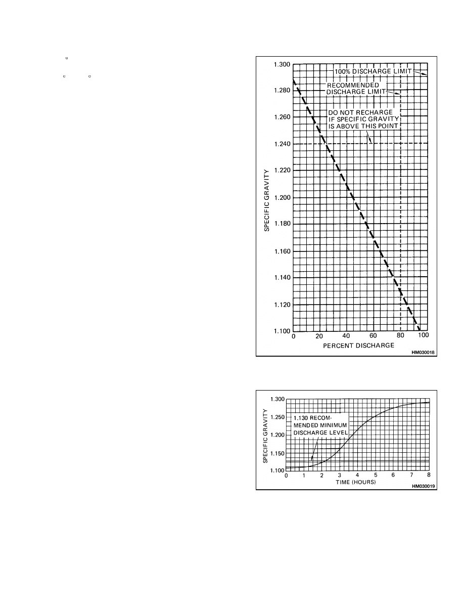
The discharge limits and the limits for the specific
gravity before the battery must be charged again are
shown in Figure 17. NEVER discharge a battery be-
low the limits shown in Figure 18. Discharging a bat-
tery beyond the design limits will decrease the ser-
vice life of the battery.
NOTE: Sometimes the capacity of a battery is not
enough to complete a work period. Check for the fol-
lowing conditions:
• The battery is too small for the job.
• The battery is not fully charged.
• The battery charger is not operating correctly.
• The battery is near the end of its service life.
Figure 17. Specific Gravity Versus Percent
Discharge
Figure 18. Specific Gravity Compared to
Charging Time
11
Battery Maintenance
2240 SRM 1
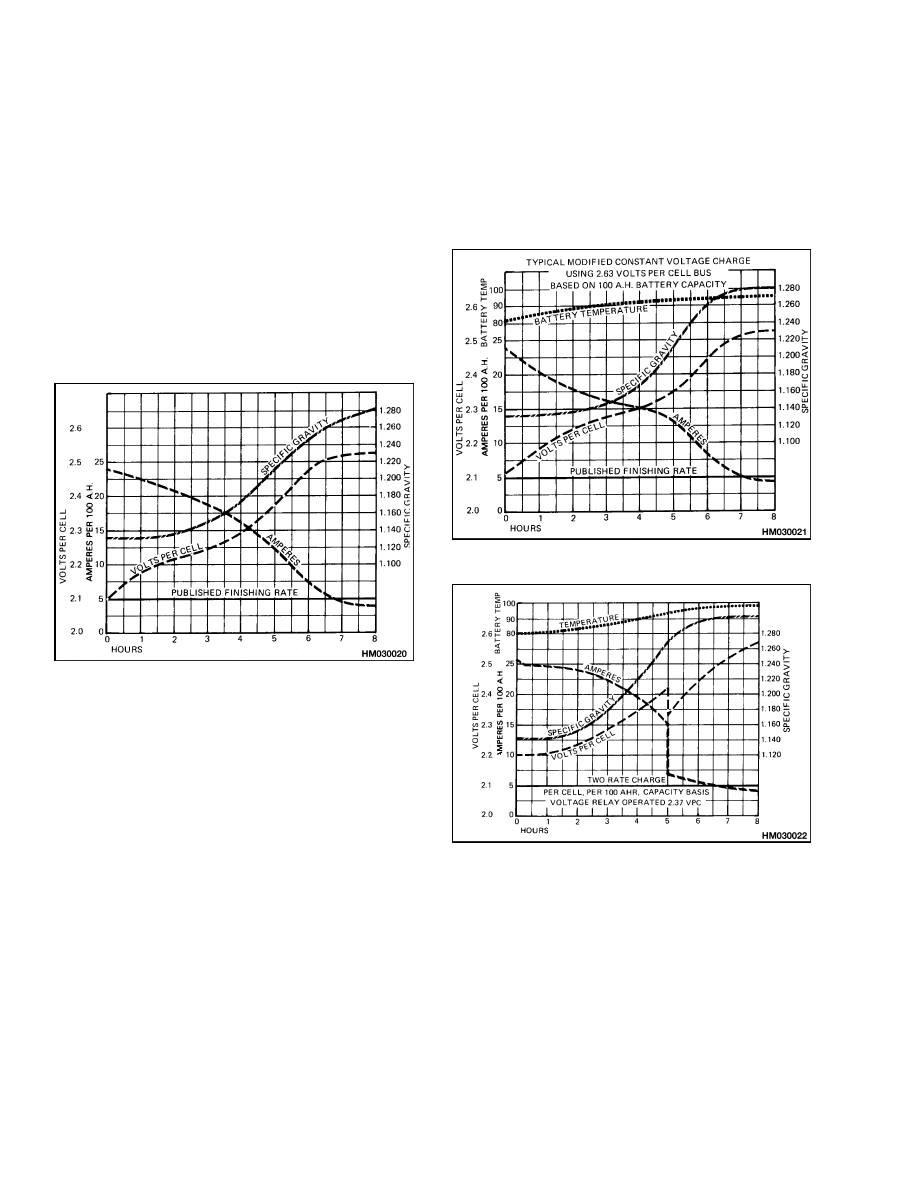
Methods of Charging
There are three methods of charging a battery.
1.
GRADUAL CHARGE. This method uses a
solid-state automatic battery charger.
The
charging rate begins at 20 to 25 amps/100
amp-hours and decreases to less than 5 amps/100
amp-hours when the battery is 80 percent
charged. The charging current decreases when
the voltage across the cell increases during the
charging cycle shown in Figure 19. The increase
in the voltage from the charger is approximately
the same as the increase in the specific gravity
in the cells.
Figure 19. Specific Gravity Compared to
Charging Time
2.
MODIFIED
CONSTANT
VOLTAGE.
This
method uses a generator to generate a con-
stant voltage that is controlled by a resistor.
When the charging current decreases, the volt-
age across the resistor increases. The increasing
voltage across the resistor causes an increasing
voltage at the battery terminals. The charging
is similar to the gradual charge. The resistor
must be correctly set, or the charging rate will
be wrong.
The typical graphs for a modified
constant voltage charger are shown in Figure 20.
3.
TWO-RATE CHARGE. This method also uses a
high charging rate at the beginning followed by
a lower rate. Two resistors control the charging
rate. One resistor controls the charging rate at
the beginning of the cycle and a second resistor
reduces the charging rate when the voltage in the
cells reaches 2.37 volts. A relay automatically
controls the second resistor. The two-rate charg-
ing cycle is shown in Figure 21.
Figure 20. Modified Constant Voltage Charger
Figure 21. Two-Rate Charging Cycle
NOTE: Many users have battery chargers that can
follow a program to automatically charge a battery
according to recommendations of the battery man-
ufacturer. Use the recommendations of the battery
manufacturer for charging the battery.
12

2240 SRM 1
Battery Maintenance
Troubleshooting Charger
Battery chargers normally operate automatically
without constant attention. It is necessary to make
a periodic check that the charger is operating cor-
rectly. Check for the following conditions:
1.
Battery temperature is too high. The temper-
ature in a battery will not normally rise more
than 14 C (25 F) during an 8-hour charging pe-
riod. Higher temperatures indicate the charging
rate needs adjustment.
2.
Continuous operation of the charger. Check the
automatic controls on the charger. Check the
charging rate. A low charging rate can be the
problem.
3.
Continuous operation of a charger at a high rate.
Normally, the charging rate begins at a high rate
and decreases as the battery becomes charged.
If the rate does not decrease, the controls need
repair or adjustment.
Knowing When Battery Is Fully Charged
WARNING
Always connect the positive cable to the pos-
itive terminal and connect the negative cable
to the negative terminal. Any other connection
will cause injury and damage.
Always charge the battery at the end of the
work period (shift).
Never let the specific
gravity decrease to a level less than the limits
shown in the manual.
Always de-energize the charger before you con-
nect or disconnect the charger from the bat-
tery.
NEVER connect the battery charger plug to
the plug of the lift truck. You can damage the
traction control circuit. Make sure the charger
voltage is the correct voltage for the battery.
1.
During charging, the voltage increases slowly.
When the battery is fully charged, the voltage
level is constant.
2.
Remove a vent cap and look in the opening. If
you see bubbles in the electrolyte, the battery is
either fully charged or in the final stage of charg-
ing.
3.
The specific gravity reading is constant and
within the limits of a charged battery. If the tem-
perature increases after the battery is charged,
the specific gravity will decrease a small amount.
4.
Constant meter indications on the charger will
indicate the end of the charging cycle.
WHERE TO CHARGE BATTERIES
To increase the service life and reduce maintenance,
a special area is needed for charging the batteries.
The following information is necessary for the design
of this area:
• Location of power supply
• Ventilation; hydrogen gas comes from the batteries
during charging
• Drains for cleaning the batteries
• Type and size of the batteries
• Type of lift trucks
• Distances the lift trucks must travel for service
• Safety regulations and instructions
Equipment Needed
• A lifting device to remove the battery from the lift
truck
• Racks to hold the batteries during charging and
storage (these racks must be made of wood or must
not be metal; metal racks that are covered with an
insulating material can be used)
• A battery charger that will charge your batteries
• Tools for maintenance
• An area with a drain for cleaning batteries and bat-
tery compartments
• Distilled water
• Air and water supplies for cleaning
• Maintenance records (see Figure 11 and Figure 12)
• A workbench
• Spare parts and repair equipment
• Protective clothing and safety equipment for han-
dling batteries
• Water source for washing eyes and preventing acid
burns
• Install a NO SMOKING sign in the service area
• Keep the charger in a clean, dry area with good
ventilation
13
Battery Maintenance
2240 SRM 1
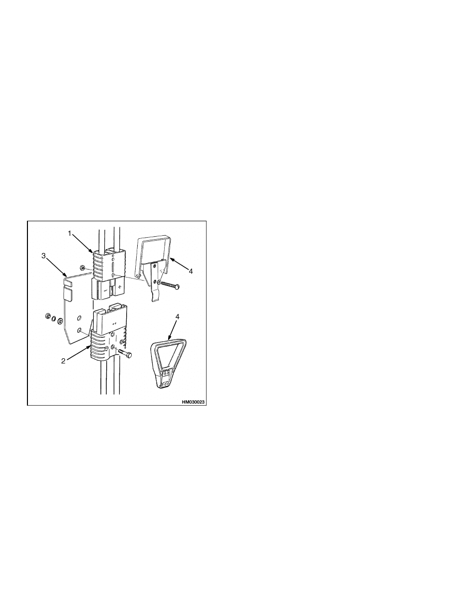
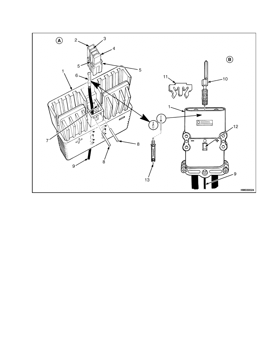
BATTERY CONNECTORS
A special heavy-duty connector is used to connect the
battery to the electrical system of the lift truck. See
Figure 22 and Figure 23. When a connector has a
handle and is within the operator’s reach, the connec-
tor is also a safety device that can be used to quickly
disconnect the battery in an emergency. Most con-
nectors have a handle to connect the two halves of the
connector. The connector can be quickly disconnected
by pulling the handle upward. This action separates
the two halves of the connector. The connector and
its attached handle must be kept in good repair so
that it will function correctly. The battery connec-
tor must be disconnected when maintenance is done
on the lift truck that does not require electric power.
The SBE, SBX, and FEM or DIN 12- volt battery con-
nectors are shown in Figure 23.
1.
SB CONNECTOR FOR BATTERY CABLES
2.
SB CONNECTOR FOR POWER CABLES TO
LIFT TRUCK
3.
BRACKET
4.
CONNECT AND DISCONNECT HANDLES
Figure 22. SB Battery Connector
BATTERY CARE
1.
Keep batteries clean. Remove any spilled elec-
trolyte.
2.
DO NOT overcharge the battery. This action will
damage the battery.
3.
DO NOT discharge the battery to less than the
recommendation. A deep discharge will shorten
the battery life.
4.
Charge batteries in an area with good ventilation
to remove explosive gases and acid fumes.
5.
Keep the electrolyte at the correct level. Check
the electrolyte level before and after charging the
battery. Use distilled water. Do not add acid.
6.
Prevent batteries from freezing.
7.
Keep batteries charged. A discharged battery in
storage will shorten the battery life.
8.
Use a battery charger that is correct for the bat-
tery. A battery charger that is set for an am-
pere-hour rate that is too high will cause a high
internal heat and damage the battery. A low am-
pere-hour rate setting on a battery charger can
require a longer charging time but will not dam-
age the battery.
9.
When batteries are moved, make sure a short
circuit does not occur. See the Safety Procedures
in Battery Maintenance of this section.
14
2240 SRM 1
Battery Maintenance
NOTE: INDICATOR INSERT (2). GREEN - FOR BATTERY WITH CELL CAPS. GRAY - FOR BATTERY WITH
SEALED CELLS.
NOTE: CONNECTOR BODY COLOR [ANDERSON SBE CONNECTOR ONLY (1)]. GRAY - 36-VOLT BATTERY.
BLUE - 48-VOLT BATTERY. GREEN - 72-VOLT BATTERY. BLACK - 80-VOLT BATTERY.
A. ANDERSON SBE OR SBX CONNECTOR
B. FEM OR DIN CONNECTOR
1.
HALF OF CONNECTOR SET
2.
RED HOUSING FOR +12 VOLT "BATTERY TAP"
3.
LOCK SPRING (TIP OF CONTACT MUST LOCK
OVER TOP OF LOCK SPRING)
4.
BLACK CONNECTOR HOUSING (ASSEMBLED
ON RED HOUSING WITH SLOTS FOR LOCK
PINS ALIGNED AS SHOWN - NO WIRE OR
CONTACT IN HOUSING)
5.
SLOT FOR LOCK PIN
6.
CONTACT FOR CONNECTOR OF +12 VOLT
BATTERY TAP
7.
KEY [RED (2) AND BLACK (4) CONNECTORS
ALIGN ON KEY]
8.
LOCK PINS FOR +12 VOLT CONNECTOR (MUST
INSTALL FROM FRONT OF CONNECTOR
THROUGH RED AND BLACK CONNECTORS)
9.
+12 VOLT WIRE TO TRUCK (TRUCK HALF) OR
TO BATTERY (BATTERY HALF)
10. INDICATOR INSERT FOR BATTERY VOLTAGE
AND BATTERY TYPE [ROTATE FOR CORRECT
VOLTAGE IN WINDOW (12); COLOR SHOWS
BATTERY TYPE]
11. LOCK FOR ALL CABLE TERMINALS AND
INDICATOR
12. WINDOW SHOWING BATTERY VOLTAGE
13. IN-LINE FUSE ASSEMBLY AND CONTACT
FOR +12 VOLT CONNECTOR (TRUCK HALF
OF BATTERY CONNECTOR ONLY) (SBE/SBX
CONTACT SHOWN)
Figure 23. Detail of Battery Connectors With +12 Volt Tap
15

NOTES
____________________________________________________________
____________________________________________________________
____________________________________________________________
____________________________________________________________
____________________________________________________________
____________________________________________________________
____________________________________________________________
____________________________________________________________
____________________________________________________________
____________________________________________________________
____________________________________________________________
____________________________________________________________
____________________________________________________________
____________________________________________________________
____________________________________________________________
____________________________________________________________
____________________________________________________________
____________________________________________________________
____________________________________________________________
____________________________________________________________
16


TECHNICAL PUBLICATIONS
2240 SRM 1
11/03 (3/03)(2/02)(3/00)(9/96)(5/96)(2/94)(1/83)(7/78) Printed in United Kingdom
Document Outline
- toc
- Industrial Battery
- Safety Precautions Maintenance and Repair
- General
- Lead-Acid Batteries
- Specific Gravity
- Chemical Reaction in a Cell
- Electrical Terms
- Battery Selection
- Battery Voltage
- Battery as a Counterweight
- Battery Ratings
- Battery Maintenance
- tables
Wyszukiwarka
Podobne podstrony:
1452929 2200SRM0679 (11 2003) UK EN
1475871 1800SRM0785 (11 2003) UK EN
1470230 1600SRM0786 (11 2003) UK EN
1452929 2200SRM0679 (11 2003) UK EN
1494953 1400SRM0944 (09 2003) UK EN
1466205 2100SRM0735 (11 2004) UK EN
897394 1900SRM0453 (09 2003) UK EN
1494145 8000SRM0940 (10 2003) UK EN
897493 1600SRM0512 (11 1995) UK EN
1466241 1600SRM0732 (10 2003) UK EN
1554636 8000SRM1080 (11 2004) UK EN
1498445 1400SRM0945 (09 2003) UK EN
910092 1900SRM0098 (07 2003) UK EN
1510463 1400SRM0984 (09 2003) UK EN
1466211 2000SRM0754 (12 2003) UK EN
więcej podobnych podstron