
01-1
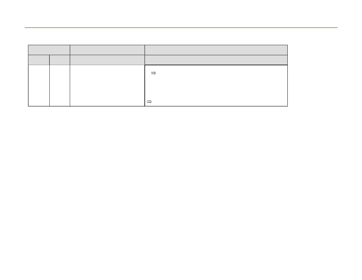
Motronic system, On Board
Diagnostic (OBD)
On Board Diagnostic, technical data
Equipment
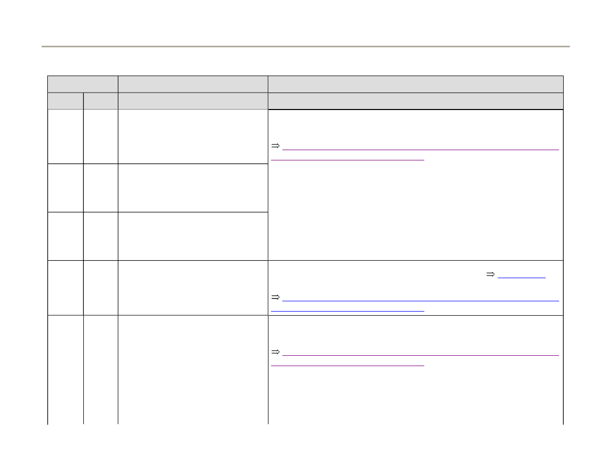
The advantages of OBD can only be fully
exploited by using the vehicle diagnostic, testing
and information system VAS5051 or the
VAG1551 scan tool, in operating mode 1 "Rapid
data transfer."
The DTC memory is equipped with a permanent
memory and therefore does not depend on the
voltage (power) supply.
The stored malfunctions will be displayed after
checking the Diagnostic Trouble Code (DTC)
memory
Page 01-14
.
After eliminating malfunctions the DTC memory
must be erased
Page 01-14
.
Note:
Every time the DTC memory is erased and the
voltage supply to the Motronic Engine Control
Module (ECM) -J220- has been interrupted a
new readiness code must be generated
Page 01-116
.
Page 1 of 183
Motronic system, On Board Diagnostic (OBD)
1/17/2006
http://127.0.0.1:8080/audi/servlet/Display?action=Goto&type=repair&id=AUDI.C5.FU03.01.1.110.11

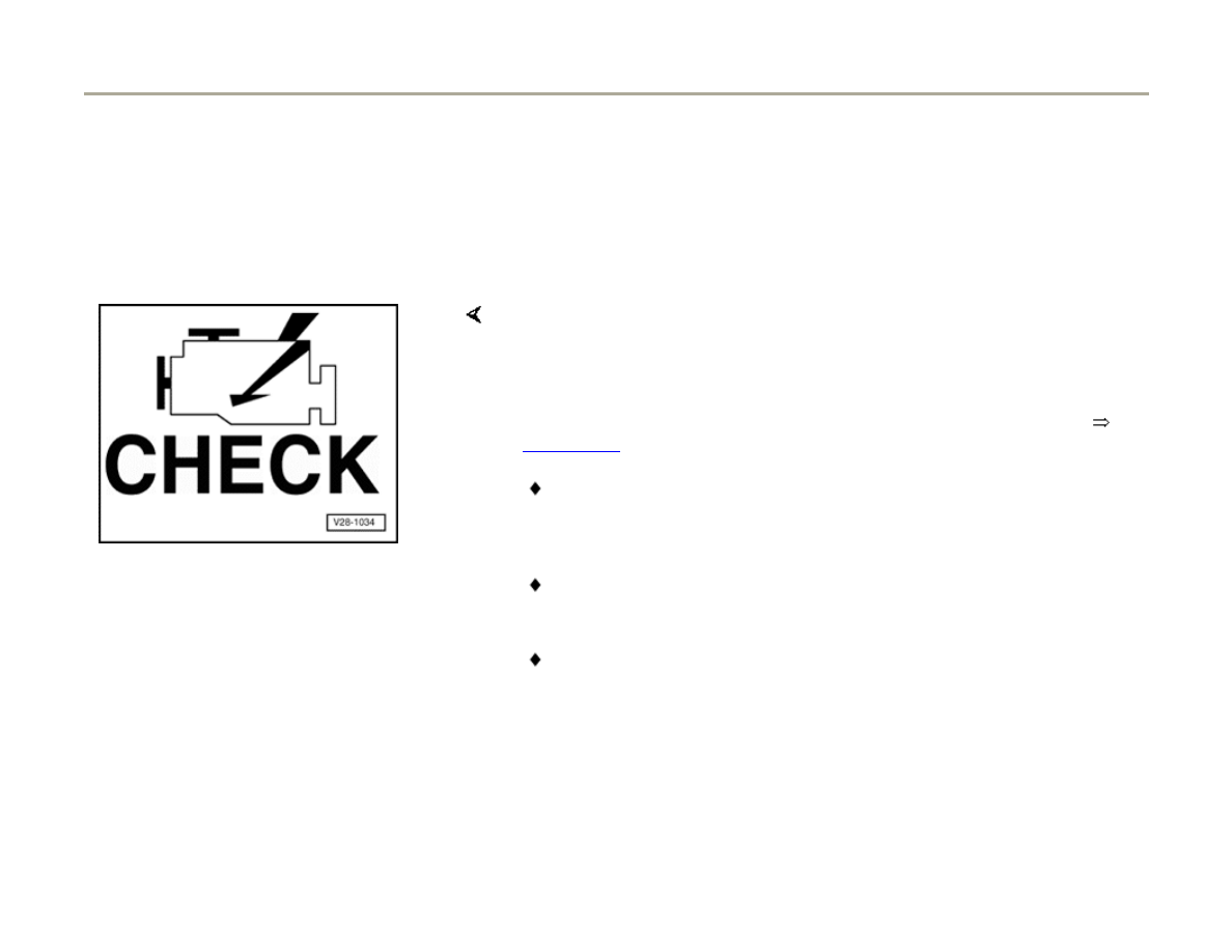
The Exhaust Malfunction Indicator Light (MIL) in
the instrument cluster will be switched on if the
ECM recognizes malfunctions that have an
effect (decrease emission values) on exhaust
emissions
Page 01-2
.
Malfunctions relating to the electronic throttle
are also indicated by the Electronic Power
Control (EPC) warning light in the instrument
cluster.
Page 2 of 183
Motronic system, On Board Diagnostic (OBD)
1/17/2006
http://127.0.0.1:8080/audi/servlet/Display?action=Goto&type=repair&id=AUDI.C5.FU03.01.1.110.11
01-2
Exhaust Malfunction Indicator Light
(MIL), significance
If the Engine Control Module (ECM) recognizes
emission related malfunctions, this is indicates by
the MIL coming on.
MIL in instrument cluster
Note:
When a recognized malfunction switches on the MIL, it will either blink or
light continuously. In either case, the DTC memory must be checked
Page 01-14
.
Blinking MIL: If the MIL starts to blink, there is a malfunction that can
lead to damage of the Three Way Catalytic Converter (TWC). In this
case driving should only continue with reduced power until the MIL
goes out or stays on continuously.
If the MIL lights continuously, there is malfunction that affects exhaust
emissions. In this case the DTC memory of the ECM and
Transmission Control Module (TCM) (if equipped) must be checked.
Some malfunctions may occur without causing the MIL to come on.
When driveability or performance problems are reported and there is
no indication from the MIL, the operation of the MIL must be checked.
In addition, the DTC memory of the ECM and TCM must be checked,
as there may be malfunctions stored that do not switch the MIL on
immediately.
Page 3 of 183
Motronic system, On Board Diagnostic (OBD)
1/17/2006
http://127.0.0.1:8080/audi/servlet/Display?action=Goto&type=repair&id=AUDI.C5.FU03.01.1.110.11

01-3
Checking function
- Switch ignition on.
MIL must light up
If the MIL does not light up with ignition switched
on:
Cause:
MIL is not
activated or does
not light up
because of an
open circuit.
Corrective action:
MIL must light up.
If the MIL does not light up:
- Switch ignition off.
- Connect VAG1598/31 test
box
Page 24-20
- Bridge sockets 2 and 47 on
test box
- Switch ignition on.
- Switch ignition off.
- Check whether lamp is
burned out and test voltage
supply to lamp wiring
diagram.
Page 4 of 183
Motronic system, On Board Diagnostic (OBD)
1/17/2006
http://127.0.0.1:8080/audi/servlet/Display?action=Goto&type=repair&id=AUDI.C5.FU03.01.1.110.11

If the lamp and the voltage
supply are OK:
- Check for open circuit or
short circuit in wiring
between engine control
module and MIL using wiring
diagram. Determine and
eliminate malfunction.
If there are no malfunctions in
the wiring to the MIL:
Malfunction
cause:
Engine control module (ECM)
faulty
Replace Engine
Control Module (ECM)
Page 24-24
.
Page 5 of 183
Motronic system, On Board Diagnostic (OBD)
1/17/2006
http://127.0.0.1:8080/audi/servlet/Display?action=Goto&type=repair&id=AUDI.C5.FU03.01.1.110.11

01-4
If MIL remains lit for more than 3 seconds (i.e.
continuously) when ignition is on, proceed with
test as follows:
- Start engine and allow it to run at idling speed.
MIL should go out.
If the MIL does not go out:
- Check DTC memory of Engine Control Module
(ECM)
Page 01-14
.
If no DTCs are stored:
Cause:
MIL is activated
via short circuit
to Ground
(GND).
Corrective action:
If the specification is not
reached:
- Switch ignition off.
- Connect VAG1598/31 test
box
Page 24-20
- Measure resistance between
vehicle Ground and socket 47
on test box. Specification:
infinity (because wire should
not have any direct Ground
connection)
Page 6 of 183
Motronic system, On Board Diagnostic (OBD)
1/17/2006
http://127.0.0.1:8080/audi/servlet/Display?action=Goto&type=repair&id=AUDI.C5.FU03.01.1.110.11

- Determine and eliminate
short circuit to Ground in wiring
between engine control
module and MIL using wiring
diagram.
If there are no malfunctions in
the wiring to the MIL:
Malfunction
cause:
Engine control module (ECM)
faulty
Replace Engine Control
Module (ECM)
Page 24-24
.
Page 7 of 183
Motronic system, On Board Diagnostic (OBD)
1/17/2006
http://127.0.0.1:8080/audi/servlet/Display?action=Goto&type=repair&id=AUDI.C5.FU03.01.1.110.11
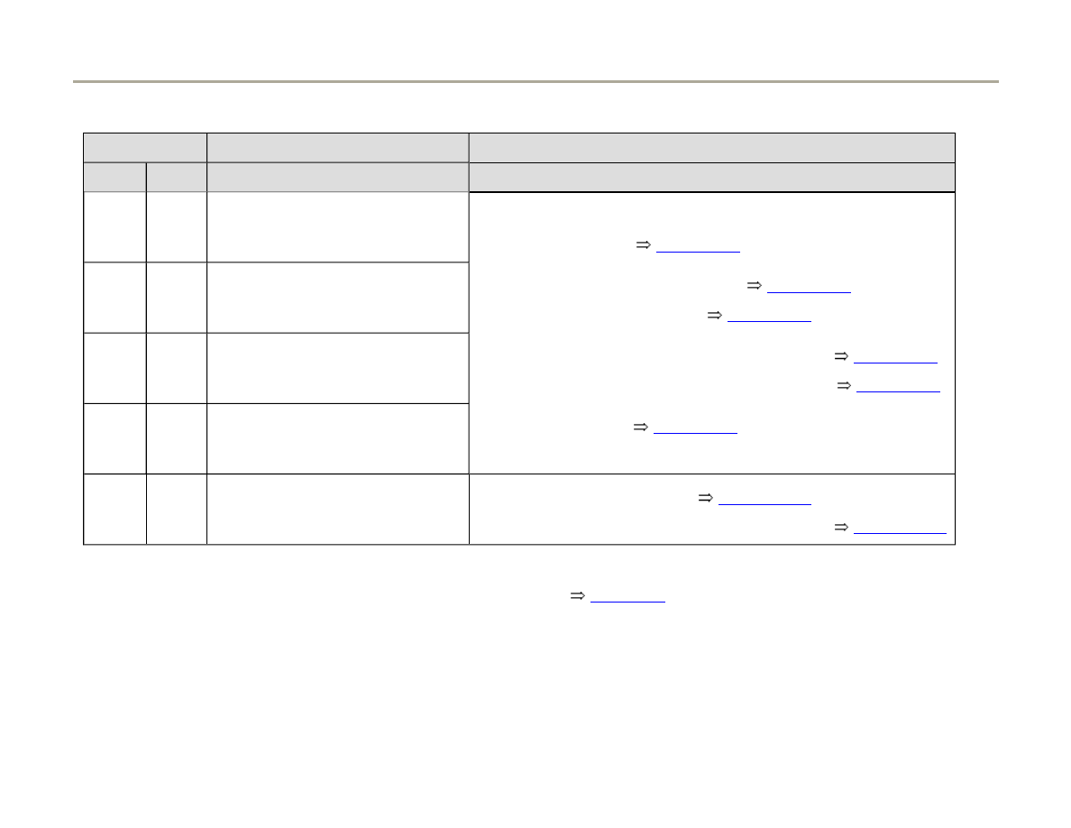
01-5
Available functions
The prerequisites for selecting the desired
functions can be taken from the following table.
Address words and functions on VAG1551 scan tool
Ignition ON,
engine not running
Engine idling Vehicle being driven
Address words
00
Automatic Test Sequence
yes
yes
yes
01
Engine Electronics
yes
yes
yes
Functions
01
Check Control Module Version
yes
yes
yes
02
Check DTC Memory
yes
yes
yes
03
Output Diagnostic Test Mode (DTM)
yes
no
no
04
Basic setting
yes
yes
yes
05
Erase DTC Memory
yes
yes
yes
06
End Output
yes
yes
yes
07
Code Control Module
no
no
no
08
Read Measuring Value Block
yes
yes
yes
Page 8 of 183
Motronic system, On Board Diagnostic (OBD)
1/17/2006
http://127.0.0.1:8080/audi/servlet/Display?action=Goto&type=repair&id=AUDI.C5.FU03.01.1.110.11
01-6
Mode under Address word 33:
Mode 1: Transmit diagnostic data
Switch ignition on or let engine run at idle
Mode 2: Transmit operating conditions
Switch ignition on or let engine run at idle
Mode 3: Check DTC Memory
Switch ignition on or let engine run at idle
Mode 4: Erase diagnostic data
Switch ignition on or let engine run at idle
Mode 5: Output of oxygen sensor signals Switch ignition on or let engine run at idle
Mode 6: Transmit measured values
Switch ignition on or let engine run at idle
Mode 7: Check DTC Memory
Switch ignition on or let engine run at idle
Mode 8: Check tank leak test
Switch ignition on or let engine run at idle
Mode 9: Read out vehicle information
Let engine run at idle
Mode 1 to 9 can be selected under address word 33.
Individual measured values can be read out under mode 1. Mode 1 is not recommended for authorized Audi service
centers, since this data can be obtained much more accurately under address word/01 function 04 or function 08.
Mode 2 displays operating conditions, for which malfunctions are recognized.
With mode 3 the DTC memory will be checked and with mode 4 the DTC memory will be erased.
Page 9 of 183
Motronic system, On Board Diagnostic (OBD)
1/17/2006
http://127.0.0.1:8080/audi/servlet/Display?action=Goto&type=repair&id=AUDI.C5.FU03.01.1.110.11

01-7
Mode 5 displays the static dimensions of the oxygen sensors, which are legally required. Since these dimensions are not
directly relevant to oxygen sensor diagnostics, mode 5 is insignificant for the authorized Audi center.
With mode 6 all measured values can be checked from components and systems that are not constantly monitored.
Using mode 7, DTCs can be checked for which the Malfunction Indicator Light (MIL) is not yet lit (MIL is not on, no DTCs
under mode 3).
Under mode 8 the tank leak test will be checked.
With mode 9 the following vehicle information can be read out: Vehicle Identification Number (VIN), Part number and
program/data level of the engine control module and the check sum (this value is a internal calculated value).
Page 10 of 183
Motronic system, On Board Diagnostic (OBD)
1/17/2006
http://127.0.0.1:8080/audi/servlet/Display?action=Goto&type=repair&id=AUDI.C5.FU03.01.1.110.11
01-8
Vehicle diagnostic, testing and
information system VAS5051 or
VAG1551 Scan Tool, connecting and
selecting functions
Requirements
Fuses for engine electronics OK
Fuel pump relay OK
Battery voltage at least 11 V
Ground (GND) connection for engine and
transmission OK
- Switch ignition off.
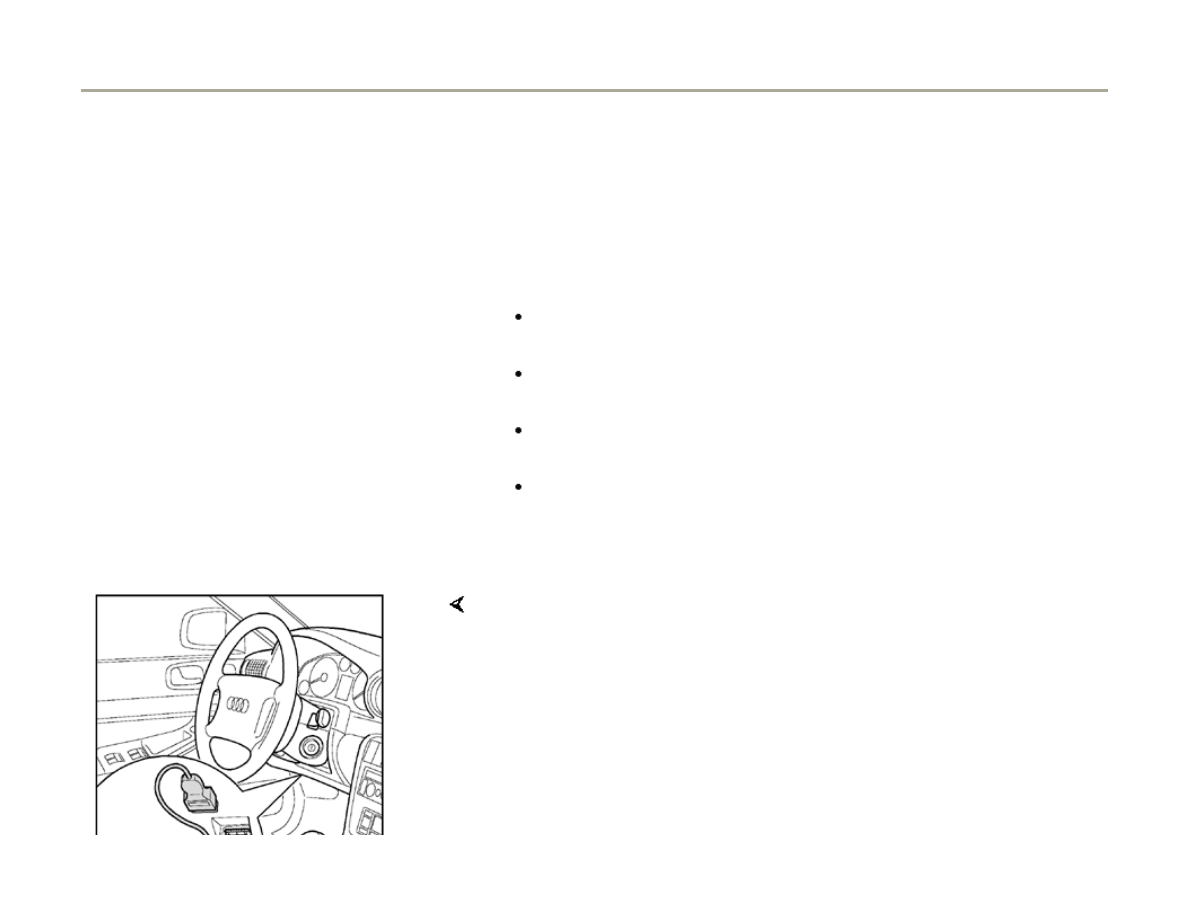
Note:
The Data Link Connector (DLC) is located below the instrument panel, to
the left of the steering column.
- Connect vehicle diagnostic, testing and information system VAS5051
with VAS5051/1 diagnostic cable. As an alternative, connect VAG1551
scan tool with VAG1551/3B diagnostic cable.
Page 11 of 183
Motronic system, On Board Diagnostic (OBD)
1/17/2006
http://127.0.0.1:8080/audi/servlet/Display?action=Goto&type=repair&id=AUDI.C5.FU03.01.1.110.11

01-9
WARNING!
When performing a road test and checks, the
vehicle diagnostic, testing and information
system VAS5051 as well as the VAG1551
may be secured only on rear seat, from
where it is to be operated by a second
technician.
Please follow safety precautions
Page 24-1
Note:
Only the procedure for OBD VAG1551 is
described below. For details of how to use the
vehicle diagnostic, testing and information
system VAS5051, please refer to its operating
manual.
VAG - On Board Diagnostic
HELP
1 - Rapid data transfer*
2 - Blink code output*
Indicated on display
* Appears alternately
Page 12 of 183
Motronic system, On Board Diagnostic (OBD)
1/17/2006
http://127.0.0.1:8080/audi/servlet/Display?action=Goto&type=repair&id=AUDI.C5.FU03.01.1.110.11

01-10
- If no display appears, check diagnostic
cables:
Electrical Wiring Diagrams, Troubleshooting &
Component Locations
Depending on the function required:
- Switch ignition on.
or
Start engine
Page 01-5
, table of available
functions.
- Switch on printer with PRINT button (indicator
light in button lights up).
- Press button -1- to select "Rapid data transfer"
operating mode.
Rapid data transfer
HELP
Insert address word XX
Indicated on display
Rapid data transfer
Q
01 - Engine Electronics
- Press buttons -0- and -1- to select "Engine electronics" address word
01.
- Press -Q- button to confirm input.
Page 13 of 183
Motronic system, On Board Diagnostic (OBD)
1/17/2006
http://127.0.0.1:8080/audi/servlet/Display?action=Goto&type=repair&id=AUDI.C5.FU03.01.1.110.11

01-11
Rapid data transfer
HELP
Control module does not answer
If the display shows one of the messages reproduced here, run through
the troubleshooting procedure for diagnostic wire.
Electrical Wiring Diagrams, Troubleshooting and Component Locations.
Rapid data transfer
HELP
K wire not switching to Ground
Rapid data transfer
HELP
K wire not switching to B+
Page 14 of 183
Motronic system, On Board Diagnostic (OBD)
1/17/2006
http://127.0.0.1:8080/audi/servlet/Display?action=Goto&type=repair&id=AUDI.C5.FU03.01.1.110.11

01-12
Control module identification (example)
4D0907551.. 2.7L V6/5VT
G 0002..
Coding 06612
WSC 06388
The display on VAG1551 will show the control module identification, for
example:
1)
The engine is a so called Biturbo engine, meaning the engine is
equipped with two turbochargers. "Bi" (latin) stand for two.
4D0907551...
Engine Control Module (ECM) Part No.
2.7 Liter
Engine displacement
V6 / 5VT
Engine configuration
(V6 5-valve Turbo
1
)
G or no
display
"G" for vehicles with Cruise control system or not
0002
ECM Software version
Coding
06612
Coding of ECM
WSC 06388
Dealership code of VAG1551 with which the last
coding was carried out
Page 15 of 183
Motronic system, On Board Diagnostic (OBD)
1/17/2006
http://127.0.0.1:8080/audi/servlet/Display?action=Goto&type=repair&id=AUDI.C5.FU03.01.1.110.11

01-13
If the coding differs from the vehicle version,
then:
- Check coding of Engine Control Module (ECM)
Page 01-103
Coding ECM
- Press button.
Rapid data transfer
HELP
Select function XX
Indicated on display
Note:
After pressing the HELP button, an overview of the possible functions is
printed out.
Page 16 of 183
Motronic system, On Board Diagnostic (OBD)
1/17/2006
http://127.0.0.1:8080/audi/servlet/Display?action=Goto&type=repair&id=AUDI.C5.FU03.01.1.110.11

01-14
Diagnostic Trouble Code (DTC) Memory,
checking and erasing
- Connect vehicle diagnostic, testing and
information system VAS5051 or VAG1551 scan
tool and select "Engine Electronics" by entering
address word 01
Page 01-8
. Engine must be
idling.
Only if engine does not start:
- Check engine with ignition switched on.
- Switch on printer with PRINT button (indicator
light in button lights up).
Rapid data transfer
HELP
Select function XX
Indicated on display
- Operate scan tool according to information on display.
- Press buttons -0- and -2- to select function "Check DTC Memory" and
confirm entry with -Q- button.
Page 17 of 183
Motronic system, On Board Diagnostic (OBD)
1/17/2006
http://127.0.0.1:8080/audi/servlet/Display?action=Goto&type=repair&id=AUDI.C5.FU03.01.1.110.11

01-15
No DTC recognized
Indicated on display
or
- Press button.
X DTC recognized
Indicated on display
The stored malfunctions will be displayed and printed out in sequence.
Note:
- Locate and eliminate printed out malfunctions according to DTC table
Page 01-18
.
If no malfunction is stored in the DTC memory, do not erase memory,
otherwise readiness code is reset.
If the DTC memory was erased, generate new readiness code
Page 01-116
.
Page 18 of 183
Motronic system, On Board Diagnostic (OBD)
1/17/2006
http://127.0.0.1:8080/audi/servlet/Display?action=Goto&type=repair&id=AUDI.C5.FU03.01.1.110.11

01-16
- Press button.
Rapid data transfer
HELP
Select function XX
Indicated on display:
Note:
- Press buttons -0- and -5- to select function "DTC Memory" and confirm
entry with -Q- button.
Attention!
DTC memory was not checked
Indicated on display:
Test sequence has not been followed.
- Check DTC memory.
Under the following conditions the DTC memory will NOT be erased:
If ignition was switched off after DTC memory has been checked.
A static malfunction has not been eliminated.
Page 19 of 183
Motronic system, On Board Diagnostic (OBD)
1/17/2006
http://127.0.0.1:8080/audi/servlet/Display?action=Goto&type=repair&id=AUDI.C5.FU03.01.1.110.11

01-17
Rapid data transfer
DTC Memory is erased!
Indicated on display
Note:
During testing and repair work, malfunctions can be recognized from other
control modules (e.g. disconnected harness connectors). Therefore, on
completion, the DTC memories of all control modules must be checked
and erased.
End output
- Press button.
- After repairs, check DTC memory again.
Rapid data transfer
HELP
Select function XX
Indicated on display
- Press buttons -0- and -6- to select function "End Output" and confirm
entry with -Q- button.
Rapid data transfer
HELP
Insert address word XX
Indicated on display
- Switch ignition off and disconnect diagnostic Data Link Connector
(DLC).
Page 20 of 183
Motronic system, On Board Diagnostic (OBD)
1/17/2006
http://127.0.0.1:8080/audi/servlet/Display?action=Goto&type=repair&id=AUDI.C5.FU03.01.1.110.11

01-18
Diagnostic Trouble Code (DTC) table
Note:
If malfunctions occur in the sensors and components being monitored, they will be stored in the DTC memory together
with an indication of the type of malfunction. Notes on Engine Power Control (EPC) (drive by wire)
Page 24-137
.
Malfunctions relating to the electronic throttle are also indicated by the EPC (Electronic Power Control) warning light in the
instrument cluster.
Malfunctions which adversely affect exhaust emissions are indicated by an Exhaust Malfunction Indicator Light (MIL), the
MIL is located in the instrument cluster. As soon as certain malfunctions are recognized, the MIL is switched on
immediately. There are also malfunctions where the MIL is switched on only after the engine is started again.
Sporadically occurring malfunctions (temporary malfunctions) will be indicated on the VAG1551 display as "SP."
The DTC table is arranged according to the 5-digit DTC in the left-hand column.
If a malfunction is stored in the DTC memory and then does not occur again during the next 40 engine warm-up phases,
the DTC will be automatically erased.
Components that are indicated as being faulty by the VAG1551 should not be replaced immediately. Always start by
checking the wiring, connectors and Ground (GND) connections for the component using the current wiring diagram. This
is particularly important in the case of sporadic malfunctions (indicated by the letters "SP"on the scan tool display).
If the connector for the engine control module is disconnected or if the battery is disconnected, all the learned values
(adaptation values) stored in the control module will be erased, although the contents of the DTC memory will remain
intact. The next time the engine is started the idling may be rough at first. In this case let the engine run at idle for a few
Page 21 of 183
Motronic system, On Board Diagnostic (OBD)
1/17/2006
http://127.0.0.1:8080/audi/servlet/Display?action=Goto&type=repair&id=AUDI.C5.FU03.01.1.110.11

minutes until the adaptation is fully carried out.
After erasing the DTC memory
Page 01-14
, generate a new readiness code
Page 01-116
.
Page 22 of 183
Motronic system, On Board Diagnostic (OBD)
1/17/2006
http://127.0.0.1:8080/audi/servlet/Display?action=Goto&type=repair&id=AUDI.C5.FU03.01.1.110.11
01-19
DTC
Description of Malfunction
Corrective action
SAE V.A.G
P0010 16394 Camshaft position actuator
circuit, Bank 1
Malfunction
2)
Repair Manual, 2.7 Liter V6 V5 BiTurbo Engine Mechanical, Engine
Code(s); APB, BEL, Repair Group 15
- Check camshaft adjustment.
P0011 16395 Retarded camshaft adjustment,
Bank 1
Specification not achieved
2)
P0012 16396 Advanced camshaft
adjustment, Bank 1
Specification not achieved
2)
P0020 16404 Camshaft position actuator
circuit, Bank 2
Malfunction
2)
P0021 16405 Retarded camshaft adjustment,
Bank 2
Specification not achieved
2)
P0022 16406 Advanced camshaft
adjustment, Bank 2
Specification not achieved
2)
Page 23 of 183
Motronic system, On Board Diagnostic (OBD)
1/17/2006
http://127.0.0.1:8080/audi/servlet/Display?action=Goto&type=repair&id=AUDI.C5.FU03.01.1.110.11

2)
With this malfunction the exhaust Malfunction Indicator Light (MIL) is only switched on by the ECM, if the malfunction is
recognized after the engine has been restarted. Significance of MIL
Page 01-2
.
Page 24 of 183
Motronic system, On Board Diagnostic (OBD)
1/17/2006
http://127.0.0.1:8080/audi/servlet/Display?action=Goto&type=repair&id=AUDI.C5.FU03.01.1.110.11
01-20
DTC
Description of malfunction
Corrective action
SAE
VAG
P0101 16485 Mass Air Flow (MAF) sensor -
G70-
Implausible signal
- Check Mass Air Flow (MAF) sensor -G70
Page 24-66
- Check hose setup of crankcase ventilation for secure seating and
proper seal.
P0102 16486 Mass or Volume Air Flow
Circuit
Low input
2)
P0103 16487 Mass or Volume Air Flow
Circuit
High Input
2)
P0106 16490 Manifold Abs.Pressure or Bar.
Pressure
Implausible signal
2) 4)
Repair Manual, 2.7L V6 V5 BiTurbo Engine Mechanical, Engine Code
(s); APB, BEL; Repair Group 21
- Check charge air pressure sensor -G31
2)
With this malfunction the exhaust Malfunction Indicator Light (MIL) is only switched on by the ECM, if the malfunction is
recognized after the engine has been restarted. Significance of MIL
Page 01-2
.
4)
Absolute manifold pressure will be determined by the Charge Air Pressure Sensor -G31 (instead of displayed -G71); the air
pressure is determined by the Barometric Pressure (BARO) Sensor -F96 (in Engine Control Module (ECM))
Page 25 of 183
Motronic system, On Board Diagnostic (OBD)
1/17/2006
http://127.0.0.1:8080/audi/servlet/Display?action=Goto&type=repair&id=AUDI.C5.FU03.01.1.110.11
01-21
DTC
Description of malfunction
Corrective action
SAE
VAG
P0111 16495 Intake Air Temp. Circ.
Implausible signal
2)
- Check Intake Air Temperature (IAT) sensor
Page 28-28
P0112 16496 Intake Air Temp. Circ.
Low Input
2)
P0113 16497 Intake Air Temp.
High Input
2)
P0116 16500 Engine Coolant Temp. Circ.
Implausible signal
- Check Engine Coolant Temperature (ECT) sensor
Page 28-36
P0117 16501 Engine Coolant Temp. Circ.
Low Input
2)
P0118 16502 Engine Coolant Temp. Circ.
High Input
2)
2)
With this malfunction the exhaust Malfunction Indicator Light (MIL) is only switched on by the ECM, if the malfunction is
recognized after the engine has been restarted. Significance of MIL
Page 01-2
.
Page 26 of 183
Motronic system, On Board Diagnostic (OBD)
1/17/2006
http://127.0.0.1:8080/audi/servlet/Display?action=Goto&type=repair&id=AUDI.C5.FU03.01.1.110.11
01-22
DTC
Description of malfunction
Corrective action
SAE
VAG
P0130 16514 02 Sensor Circ., Bank1-
Sensor1
Malfunction
2)
- Check oxygen sensor control or oxygen sensor heater and wiring
Page 24-76
P0131 16515 02 Sensor Circ., Bank1-
Sensor1
Low Voltage
2)
P0132 16516 02 Sensor Circ., Bank1-
Sensor1
High Voltage
2)
P0133 16517 02 Sensor Circ., Bank1-
Sensor1
Slow Response
2)
P0134 16518 02 Sensor Circ., Bank1-
Sensor1
No Activity Detected
2)
2)
With this malfunction the exhaust Malfunction Indicator Light (MIL) is only switched on by the ECM, if the malfunction is
recognized after the engine has been restarted. Significance of MIL
Page 01-2
.
Page 27 of 183
Motronic system, On Board Diagnostic (OBD)
1/17/2006
http://127.0.0.1:8080/audi/servlet/Display?action=Goto&type=repair&id=AUDI.C5.FU03.01.1.110.11
01-23
DTC
Description of
malfunction
Corrective action
SAE
VAG
P0136 16520 02 Sensor Circ., Bank1-
Sensor2
Electr. fault in circuit
2)
- Check oxygen sensor heater
Page 24-111
P0137 16521 02 Sensor Circ., Bank1-
Sensor2
Low Voltage
2)
- Check oxygen sensor signal wire and activation
Page 24-119
P0138 16522 02 Sensor Circ., Bank1-
Sensor2
High Voltage
2)
P0139 16523 02 Sensor Circ., Bank1-
Sensor2
Slow Response
2)
- Check oxygen sensor and oxygen sensor control behind catalytic
converter
Page 24-97
P0140 16524 02 Sensor Circ., Bank1-
Sensor2
No Activity Detected
2)
2)
With this malfunction the exhaust Malfunction Indicator Light (MIL) is only switched on by the ECM, if the malfunction is
recognized after the engine has been restarted. Significance of MIL
Page 01-2
.
Page 28 of 183
Motronic system, On Board Diagnostic (OBD)
1/17/2006
http://127.0.0.1:8080/audi/servlet/Display?action=Goto&type=repair&id=AUDI.C5.FU03.01.1.110.11

01-24
DTC
Description of malfunction
Corrective action
SAE
VAG
P0150 16534 02 Sensor Circ., Bank2-
Sensor1
Electr. fault in circuit
2)
- Check oxygen sensor control or oxygen sensor heater and wiring
Page 24-76
P0151 16535 02 Sensor Circ., Bank2-
Sensor1
Low voltage
2)
P0152 16536 02 Sensor Circ., Bank2-
Sensor1
High Voltage
2)
P0153 16537 02 Sensor Circ., Bank2-
Sensor1
Slow Response
2)
P0154 16538 02 Sensor Circ., Bank2-
Sensor1
No Activity Detected
2)
2)
With this malfunction the exhaust Malfunction Indicator Light (MIL) is only switched on by the ECM, if the malfunction is
recognized after the engine has been restarted. Significance of MIL
Page 01-2
.
Page 29 of 183
Motronic system, On Board Diagnostic (OBD)
1/17/2006
http://127.0.0.1:8080/audi/servlet/Display?action=Goto&type=repair&id=AUDI.C5.FU03.01.1.110.11
01-25
DTC
Description of
malfunction
Corrective action
SAE
VAG
P0156 16540 02 Sensor Circ., Bank2-
Sensor2
Electr. fault in circuit
2)
- Check oxygen sensor heater
Page 24-111
P0157 16541 02 Sensor Circ., Bank2-
Sensor2
Low Voltage
2)
- Check oxygen sensor signal wire and activation
Page 24-119
P0158 16542 02 Sensor Circ., Bank2-
Sensor2
High Voltage
2)
P0159 16543 02 Sensor Circ., Bank2-
Sensor2
Slow Response
2)
- Check oxygen sensor and oxygen sensor control behind catalytic
converter
Page 24-97
P0160 16544 02 Sensor Circ., Bank2-
Sensor2
No Activity Detected
2)
- Check oxygen sensor heater
Page 24-111
2)
With this malfunction the exhaust Malfunction Indicator Light (MIL) is only switched on by the ECM, if the malfunction is
recognized after the engine has been restarted. Significance of MIL
Page 01-2
.
Page 30 of 183
Motronic system, On Board Diagnostic (OBD)
1/17/2006
http://127.0.0.1:8080/audi/servlet/Display?action=Goto&type=repair&id=AUDI.C5.FU03.01.1.110.11
01-26
DTC
Description of
malfunction
Corrective action
SAE
VAG
P0236 16620 Charge air pressure sensor
-G31-
Implausible signal
Repair Manual, 2.7L V6 5V BiTurbo Engine Mechanical, Engine Code(s):
APB, BEL; Repair Group 21
- Check Charge Air Pressure Sensor -G31
P0237 16621 Charge air pressure sensor
-G31-
Low Input
2)
P0238 16622 Charge air pressure sensor
-G31-
High Input
2)
2)
With this malfunction the exhaust Malfunction Indicator Light (MIL) is only switched on by the ECM, if the malfunction is
recognized after the engine has been restarted. Significance of MIL
Page 01-2
.
Page 31 of 183
Motronic system, On Board Diagnostic (OBD)
1/17/2006
http://127.0.0.1:8080/audi/servlet/Display?action=Goto&type=repair&id=AUDI.C5.FU03.01.1.110.11
01-27
DTC
Description of
malfunction
Corrective action
SAE
VAG
P0300 16684 Random/Multiple Cylinder
Misfire Detected
2)
- Check misfire recognition
Page 28-66
P0301 16685 Cyl.1 Misfire Detected
2)
- Check fuel tank level and fill if necessary
P0302 16686 Cyl.2 Misfire Detected
2)
- Check hose setup of crankcase ventilation for secure seating and proper
seal.
P0303 16687 Cyl.3 Misfire Detected
2)
P0304 16688 Cyl.4 Misfire Detected
2)
P0305 16689 Cyl.5 Misfire Detected
2)
P0306 16690 Cyl.6 Misfire Detected
2)
2)
With this malfunction the exhaust Malfunction Indicator Light (MIL) is only switched on by the ECM, if the malfunction is
recognized after the engine has been restarted. Significance of MIL
Page 01-2
.
Note:
The Malfunction Indicator Light (MIL) will blink if the Engine Control Module (ECM) recognizes misfires that could damage
the catalytic converters.
On malfunction which could be caused by lack of fuel (e.g.: misfire) the malfunction P1250 "Fuel level too low" will be
displayed in addition. That means, the misfire was detected due to lack of fuel in the tank and not due to a technical
Page 32 of 183
Motronic system, On Board Diagnostic (OBD)
1/17/2006
http://127.0.0.1:8080/audi/servlet/Display?action=Goto&type=repair&id=AUDI.C5.FU03.01.1.110.11

malfunction.
Depending on malfunction recognition, the MIL comes on immediately or after malfunction has been confirmed.
Page 33 of 183
Motronic system, On Board Diagnostic (OBD)
1/17/2006
http://127.0.0.1:8080/audi/servlet/Display?action=Goto&type=repair&id=AUDI.C5.FU03.01.1.110.11
01-28
DTC
Description of malfunction
Corrective action
SAE
VAG
P0321 16705 Eng. Speed Sensor -G28-
Implausible signal
2)
- Check Engine Speed (RPM) sensor
Page 28-32
P0322 16706 Eng. Speed Sensor -G28-
No Signal
2)
P0327 16711 Knock Sensor 1 -G61-
Low Input
- Check Knock Sensor (KS)
Page 28-54
P0328 16712 Knock Sensor 1 -G61
High Input
P0332 16716 Knock Sensor 2 -G66-
Low Input
P0333 16717 Knock Sensor 2 -G66-
High Input
P0341 16725 Camshaft Pos. Sensor -G40-
Range/Performance
2)
- Check Camshaft Position (CMP) sensor
Page 28-59
P0346 16730 Camshaft Pos. Sensor -G163-
Range/Performance
2)
Page 34 of 183
Motronic system, On Board Diagnostic (OBD)
1/17/2006
http://127.0.0.1:8080/audi/servlet/Display?action=Goto&type=repair&id=AUDI.C5.FU03.01.1.110.11

2)
With this malfunction the exhaust Malfunction Indicator Light (MIL) is only switched on by the ECM, if the malfunction is
recognized after the engine has been restarted. Significance of MIL
Page 01-2
.
Page 35 of 183
Motronic system, On Board Diagnostic (OBD)
1/17/2006
http://127.0.0.1:8080/audi/servlet/Display?action=Goto&type=repair&id=AUDI.C5.FU03.01.1.110.11
01-29
DTC
Description of
malfunction
Corrective action
SAE
VAG
P0421 16805 Warm Up Catalyst,
Bank 1
Efficiency Below
Threshold
2)
Repair Manual; 2.7 Liter V6 5V BiTurbo Engine Mechanical, Engine Code(s):
APB, BEL; Repair Group 26
- Generate readiness code
Page 01-110
, if same DTC is displayed again,
replace warm up catalytic converter bank 1
P0431 16815 Warm Up Catalyst,
Bank 2
Efficiency Below
Threshold
2)
Repair Manual; 2.7 Liter V6 5V BiTurbo Engine Mechanical, Engine Code(s):
APB, BEL; Repair Group 26
- Generate readiness code
Page 01-110
, if same DTC is displayed again,
replace warm up catalytic converter bank 2
2)
With this malfunction the exhaust Malfunction Indicator Light (MIL) is only switched on by the ECM, if the malfunction is
recognized after the engine has been restarted. Significance of MIL
Page 01-2
.
Important note:
The warm up catalytic converters are located between the two oxygen sensors of the relevant cylinder bank. The warm up
catalytic converters (marginally smaller than main catalytic converter) are located closer to the engine, not to be confused with
the main catalysts immediately visible once the vehicle is lifted.
Page 36 of 183
Motronic system, On Board Diagnostic (OBD)
1/17/2006
http://127.0.0.1:8080/audi/servlet/Display?action=Goto&type=repair&id=AUDI.C5.FU03.01.1.110.11
01-30
DTC
Description of
malfunction
Corrective action
SAE
VAG
P0441 16825 EVAP Emission Contr.
Sys. Incorrect
Purge Flow
2)
- Check EVAP canister purge regulator valve, perform output Diagnostic Test
Mode (DTM)
Page 01-82
P0442 16826 EVAP Emission Contr.
Sys. (Small Leak)
Leak Detected
2)
- Check EVAP system and tank ventilation system for leaks
P0455 16839 EVAP Emission Contr.
Sys. (Gross Leak)
Leak Detected
Repair Manual, Fuel Supply System, Repair Group 20
Repair Manual, Fuel Supply System, Repair Group 20
- Check EVAP system for leaks using KLI9210 EVAP tester
P0456 16840 Tank ventilation system
Pin-hole leak detected
Repair Manual, Fuel Supply System, Repair Group 20; Fuel supply, gas
engine; EVAP canister system components, servicing; tank leak diagnostic,
performing.
Repair Manual, Fuel Supply System, Repair Group 20
- Check fuel supply and ventilation systems for leaks
- Check EVAP system for leaks using KLI9210 EVAP tester
2)
With this malfunction the exhaust Malfunction Indicator Light (MIL) is only switched on by the ECM, if the malfunction is
Page 37 of 183
Motronic system, On Board Diagnostic (OBD)
1/17/2006
http://127.0.0.1:8080/audi/servlet/Display?action=Goto&type=repair&id=AUDI.C5.FU03.01.1.110.11

recognized after the engine has been restarted. Significance of MIL
Page 01-2
.
Page 38 of 183
Motronic system, On Board Diagnostic (OBD)
1/17/2006
http://127.0.0.1:8080/audi/servlet/Display?action=Goto&type=repair&id=AUDI.C5.FU03.01.1.110.11
01-31
DTC
Description of
malfunction
Corrective action
SAE
VAG
P0501 16885 Vehicle Speed Sensor
Implausible signal
2)
- Check Vehicle Speed Signal (VSS)
Page 24-180
P0506 16890 Idle Control System
RPM Lower than
Expected
2)
- Perform adaptation of Throttle Valve Control Module
Page 24-144
P0507 16891 Idle Control System
RPM Higher than
Expected
2)
- Check for unmetered (false) air
Page 24-74
- Check hose setup of crankcase ventilation for secure seating and proper seal.
P0560 16944 System Voltage
Malfunction
- Check control module voltage supply
Page 28-43
P0562 16946 System Voltage
Low Voltage
P0563 16947 System Voltage
High Voltage
P0571 16955 Cruise/Brake Switch (A)
Circ.
Incorrect Signal
- Check brake light switch and/or brake pedal switch
Page 24-183
(On Board
Diagnostic for Cruise Control System)
Page 39 of 183
Motronic system, On Board Diagnostic (OBD)
1/17/2006
http://127.0.0.1:8080/audi/servlet/Display?action=Goto&type=repair&id=AUDI.C5.FU03.01.1.110.11

Repair Manual, Electrical Equipment, Repair Group 01
2)
With this malfunction the exhaust Malfunction Indicator Light (MIL) is only switched on by the ECM, if the malfunction is
recognized after the engine has been restarted. Significance of MIL
Page 01-2
.
Page 40 of 183
Motronic system, On Board Diagnostic (OBD)
1/17/2006
http://127.0.0.1:8080/audi/servlet/Display?action=Goto&type=repair&id=AUDI.C5.FU03.01.1.110.11
01-32
DTC
Description of malfunction
Corrective action
SAE
VAG
P0601 16985 Control module faulty
2)
- Replace Engine Control Module (ECM)
Page 24-24
P0604 16988 Control module faulty
2)
P0605 16989 Control module faulty
2)
P0606 16990 Control module faulty
P0685 17069 Main relay, Motronic ECM power supply relay
-J271-
Open circuit
- Check Motronic engine control module (ECM) power
supply relay -J271-
Page 28-24
P0686 17070 Main relay, Motronic ECM power supply relay
-J271-
Short to Ground
P0687 17071 Main relay, Motronic ECM power supply relay
-J271-
Short to positive
P0688 17072 Main relay, load circuit, Motronic ECM power
supply relay -J271-
Open circuit
2)
With this malfunction the exhaust Malfunction Indicator Light (MIL) is only switched on by the ECM, if the malfunction is
recognized after the engine has been restarted. Significance of MIL
Page 01-2
.
Page 41 of 183
Motronic system, On Board Diagnostic (OBD)
1/17/2006
http://127.0.0.1:8080/audi/servlet/Display?action=Goto&type=repair&id=AUDI.C5.FU03.01.1.110.11
01-33
DTC
Description of malfunction
Corrective action
SAE
VAG
P1102 17510 O2 Sensor Heating Circ., Bank1-
Sensor1
Short to B+
2)
- Check oxygen sensor heater
Page 24-111
P1105 17513 O2 Sensor Heating Circ., Bank1-
Sensor2
Short to B+
2)
P1107 17515 O2 Sensor Heating Circ., Bank2-
Sensor1
Short to B+
2)
P1110 17518 O2 Sensor Heating Circ., Bank2-
Sensor2
Short to B+
2)
P1111 17519 O2 Control Bank 1
System too lean
- Check oxygen sensor adaptation values and oxygen sensor control
Page 24-83
P1112 17520 O2 Control Bank 1
System too rich
2)
With this malfunction the exhaust Malfunction Indicator Light (MIL) is only switched on by the ECM, if the malfunction is
recognized after the engine has been restarted. Significance of MIL
Page 01-2
.
Page 42 of 183
Motronic system, On Board Diagnostic (OBD)
1/17/2006
http://127.0.0.1:8080/audi/servlet/Display?action=Goto&type=repair&id=AUDI.C5.FU03.01.1.110.11
01-34
DTC
Description of malfunction
Corrective action
SAE
VAG
P1113 17521 Bank1-Sensor1
Internal Resistance too High
2)
- Check oxygen sensor heater
Page 24-111
P1114 17522 Bank1-Sensor2
Internal Resistance too High
2)
- Check oxygen sensor signal wire and activation
Page 24-
119
P1115 17523 O2 Sensor Heater Circ., Bank1-
Sensor1
Short to Ground
2)
- Check oxygen sensor heater
Page 24-111
P1116 17524 O2 Sensor Heater Circ., Bank1-
Sensor1
Open
2)
P1117 17525 O2 Sensor Heater Circ., Bank1-
Sensor2
Short to Ground
2)
P1118 17526 O2 Sensor Heater Circ., Bank1-
Sensor2
Open
2)
2)
With this malfunction the exhaust Malfunction Indicator Light (MIL) is only switched on by the ECM, if the malfunction is
Page 43 of 183
Motronic system, On Board Diagnostic (OBD)
1/17/2006
http://127.0.0.1:8080/audi/servlet/Display?action=Goto&type=repair&id=AUDI.C5.FU03.01.1.110.11

recognized after the engine has been restarted. Significance of MIL
Page 01-2
.
Page 44 of 183
Motronic system, On Board Diagnostic (OBD)
1/17/2006
http://127.0.0.1:8080/audi/servlet/Display?action=Goto&type=repair&id=AUDI.C5.FU03.01.1.110.11
01-35
DTC
Description of malfunction
Corrective action
SAE
VAG
P1119 17527 O2 Sensor Heater Circ., Bank2-Sensor1
Short to Ground
2)
- Check oxygen sensor heater
Page 24-111
.
P1120 17528 O2 Sensor Heater Circ., Bank2-Sensor1
Open
2)
P1121 17529 O2 Sensor Heater Circ., Bank2-Sensor2
Short to Ground
2)
P1122 17530 O2 Sensor Heater Circ., Bank2-Sensor2
Open
2)
2)
With this malfunction the exhaust Malfunction Indicator Light (MIL) is only switched on by the ECM, if the malfunction is
recognized after the engine has been restarted. Significance of MIL
Page 01-2
.
Page 45 of 183
Motronic system, On Board Diagnostic (OBD)
1/17/2006
http://127.0.0.1:8080/audi/servlet/Display?action=Goto&type=repair&id=AUDI.C5.FU03.01.1.110.11
01-36
DTC
Description of malfunction
Corrective action
SAE
VAG
P1127 17535 Long Term Fuel Trim mult., Bank1
System too rich
2)
- Road test vehicle (Fuel in engine oil)
- Check fuel pressure
Page 24-42
P1128 17536 Long Term Fuel Trim mult., Bank1
System too lean
2)
- Check Mass Air Flow (MAF) sensor
Page 24-66
- Check intake system for leaks
Page 24-74
P1129 17537 Long Term Fuel Trim mult., Bank2
System too rich
2)
- Check oxygen sensor before catalytic converter
Page 24-78
- Check oxygen sensor behind catalytic converter
Page 24-97
P1130 17538 Long Term Fuel Trim mult., Bank2
System too lean
2)
- Check fuel injectors
Page 24-52
P1131 17539 Bank2-Sensor1
Internal Resistance too High
2)
- Check oxygen sensor heater
Page 24-111
.
- Check oxygen sensor signal wire and activation
Page 24-119
2)
With this malfunction the exhaust Malfunction Indicator Light (MIL) is only switched on by the ECM, if the malfunction is
recognized after the engine has been restarted. Significance of MIL
Page 01-2
.
Note:
mult. = multiplikative means that the malfunction affects the entire RPM and load range.
Page 46 of 183
Motronic system, On Board Diagnostic (OBD)
1/17/2006
http://127.0.0.1:8080/audi/servlet/Display?action=Goto&type=repair&id=AUDI.C5.FU03.01.1.110.11
01-37
DTC
Description of malfunction
Corrective action
SAE
VAG
P1136 17544 Long Term Fuel Trim Add. Fuel,
Bank1
System too Lean
2)
- Road test vehicle (fuel in engine oil)
P1137 17545 Long Term Fuel Trim Add. Fuel,
Bank1
System too Rich
2)
- Check fuel pressure
Page 24-42
P1138 17546 Long Term Fuel Trim Add. Fuel,
Bank2
System too Lean
2)
- Check Mass Air Flow (MAF) Sensor
Page 24-66
P1139 17547 Long Term Fuel Trim Add. Fuel,
Bank2
System too Rich
2)
- Check oxygen sensor before catalytic converter
Page 24-78
- Check oxygen sensor behind catalytic converter
Page 24-97
- Check EVAP canister valve 1
Page 24-132
P1140 17548 Bank2-Sensor2
Internal Resistance too High
2)
- Check oxygen sensor heater
Page 24-111
.
- Check oxygen sensor signal wire and activation
Page 24-
119
2)
With this malfunction the exhaust Malfunction Indicator Light (MIL) is only switched on by the ECM if the malfunction is
recognized after the engine has been restarted. Significance of MIL
Page 01-2
.
Note:
Page 47 of 183
Motronic system, On Board Diagnostic (OBD)
1/17/2006
http://127.0.0.1:8080/audi/servlet/Display?action=Goto&type=repair&id=AUDI.C5.FU03.01.1.110.11

add. = additive means that the malfunction occurs only at idle.
Page 48 of 183
Motronic system, On Board Diagnostic (OBD)
1/17/2006
http://127.0.0.1:8080/audi/servlet/Display?action=Goto&type=repair&id=AUDI.C5.FU03.01.1.110.11
01-38
DTC
Description of
malfunction
Corrective action
SAE
VAG
P1141 17549 Load calculation cross
check
Out of range
Parts List
- Check if correct throttle valve control module is installed
P1142 17550 Load calculation cross
check
Lower limit exceeded
- Check mass air flow (MAF) sensor
Page 24-66
P1143 17551 Load calculation cross
check
Upper limit exceeded
- Replace Motronic ECM
Page 24-24
P1147 17555 O2 Control Bank2
System too Lean
- Check oxygen sensor adaptation values and oxygen sensor control
Page 24-83
P1148 17556 O2 Control Bank2
System too Rich
P1149 17557 O2 Control Bank1
Out of Range
- Check oxygen sensor adaptation values and oxygen sensor control
Page 24-83
P1150 17558 O2 Control Bank2
Out of Range
- Check fuel pressure
Page 24-42
- Check intake system for unmetered (false) air
Page 24-74
Page 49 of 183
Motronic system, On Board Diagnostic (OBD)
1/17/2006
http://127.0.0.1:8080/audi/servlet/Display?action=Goto&type=repair&id=AUDI.C5.FU03.01.1.110.11

2)
With this malfunction the exhaust Malfunction Indicator Light (MIL) is only switched on by the ECM if the malfunction is
recognized after the engine has been restarted. Significance of MIL
Page 01-2
.
Page 50 of 183
Motronic system, On Board Diagnostic (OBD)
1/17/2006
http://127.0.0.1:8080/audi/servlet/Display?action=Goto&type=repair&id=AUDI.C5.FU03.01.1.110.11
01-39
DTC
Description of malfunction
Corrective action
SAE
VAG
P1171 17579 Angle sensor 2 for throttle drive -
G188-
Implausible signal
1) 3)
- Check Angle sensor 2 for throttle drive -G188-
Page 24-151
.
P1172 17580 Angle sensor 2 for throttle drive -
G188-
Signal too Low
1) 3)
P1173 17581 Angle sensor 2 for throttle drive -
G188-
Signal too High
1) 3)
P1176 17584 O2 Correction Behind Catalyst,
Bank 1
Limit Attained
2)
- Check oxygen sensor aging of oxygen sensors before catalytic
converters
Page 24-90
P1177 17585 O2 Correction Behind Catalyst,
Bank 2
Limit Attained
2)
- Check oxygen sensors and oxygen sensor control behind catalytic
converters
Page 24-97
1)
With this malfunction the EPC (Electronic Power Control) Malfunction Indicator Light (MIL) in the instrument cluster is
switched on by the ECM. Significance of EPC malfunction indicator light
Page 24-140
.
2)
With this malfunction the exhaust Malfunction Indicator Light (MIL) is only switched on by the ECM if the malfunction is
Page 51 of 183
Motronic system, On Board Diagnostic (OBD)
1/17/2006
http://127.0.0.1:8080/audi/servlet/Display?action=Goto&type=repair&id=AUDI.C5.FU03.01.1.110.11

recognized after the engine has been restarted. Significance of MIL
Page 01-2
.
3)
With this malfunction the exhaust Malfunction Indicator Light (MIL) is switched on by the ECM immediately after the
malfunction has been recognized. Significance of MIL
Page 01-2
.
Page 52 of 183
Motronic system, On Board Diagnostic (OBD)
1/17/2006
http://127.0.0.1:8080/audi/servlet/Display?action=Goto&type=repair&id=AUDI.C5.FU03.01.1.110.11
01-40
DTC
Description of malfunction
Corrective action
SAE
VAG
P1198 17606 O2 Sensor Heater Circ., Bank1-Sensor2
Electrical Malfunction
2)
- Check oxygen sensor heater
Page 24-111
.
P1199 17607 O2 Sensor Heater Circ., Bank1-Sensor2
Electrical Malfunction
2)
2)
With this malfunction the exhaust Malfunction Indicator Light (MIL) is only switched on by the ECM if the malfunction is
recognized after the engine has been restarted. Significance of MIL
Page 01-2
.
Page 53 of 183
Motronic system, On Board Diagnostic (OBD)
1/17/2006
http://127.0.0.1:8080/audi/servlet/Display?action=Goto&type=repair&id=AUDI.C5.FU03.01.1.110.11
01-41
DTC
Description of malfunction
Corrective action
SAE
VAG
P1201 17609 Cylinder 1 - Fuel Injector -N30-
Electr. Malfunction in circuit
- Check fuel injectors
Page 24-48
P1202 17610 Cylinder 2 - Fuel Injector -N31-
Electr. Malfunction in circuit
P1203 17611 Cylinder 3 - Fuel Injector -N32-
Electr. Malfunction in circuit
P1204 17612 Cylinder 4 - Fuel Injector -N33-
Electr. Malfunction in circuit
P1205 17613 Cylinder 5 - Fuel Injector -N83-
Electr. Malfunction in circuit
P1206 17614 Cylinder 6 - Fuel Injector -N84-
Electr. Malfunction in circuit
2)
With this malfunction the exhaust Malfunction Indicator Light (MIL) is only switched on by the ECM if the malfunction is
recognized after the engine has been restarted. Significance of MIL
Page 01-2
.
Page 54 of 183
Motronic system, On Board Diagnostic (OBD)
1/17/2006
http://127.0.0.1:8080/audi/servlet/Display?action=Goto&type=repair&id=AUDI.C5.FU03.01.1.110.11

01-42
DTC
Description of malfunction
Corrective action
SAE
VAG
P1213 17621 Cyl. 1-Fuel Inj. -N30-
Short to B+
2)
- Check fuel injectors
Page 24-48
P1214 17622 Cyl. 2-Fuel Inj. -N31-
Short to B+
2)
P1215 17623 Cyl. 3-Fuel Inj. -N32-
Short to B+
2)
P1216 17624 Cyl. 4-Fuel Inj. -N33-
Short to B+
2)
P1217 17625 Cyl. 5-Fuel Inj. -N83-
Short to B+
2)
P1218 17626 Cyl. 6-Fuel Inj. -N84-
Short to B+
2)
2)
With this malfunction the exhaust Malfunction Indicator Light (MIL) is only switched on by the ECM if the malfunction is
recognized after the engine has been restarted. Significance of MIL
Page 01-2
.
Page 55 of 183
Motronic system, On Board Diagnostic (OBD)
1/17/2006
http://127.0.0.1:8080/audi/servlet/Display?action=Goto&type=repair&id=AUDI.C5.FU03.01.1.110.11
01-43
DTC
Description of malfunction
Corrective action
SAE
VAG
P1225 17633 Cyl. 1-Fuel Inj. -N30-
Short to Ground
2)
- Check fuel injectors
Page 24-48
P1226 17634 Cyl. 2-Fuel Inj. -N31-
Short to Ground
2)
P1227 17635 Cyl. 3-Fuel Inj. -N32-
Short to Ground
2)
P1228 17636 Cyl. 4-Fuel Inj. -N33-
Short to Ground
2)
P1229 17637 Cyl. 5-Fuel Inj. -N83-
Short to Ground
2)
P1230 17638 Cyl. 6-Fuel Inj. -N84-
Short to Ground
2)
2)
With this malfunction the exhaust Malfunction Indicator Light (MIL) is only switched on by the ECM if the malfunction is
recognized after the engine has been restarted. Significance of MIL
Page 01-2
.
Page 56 of 183
Motronic system, On Board Diagnostic (OBD)
1/17/2006
http://127.0.0.1:8080/audi/servlet/Display?action=Goto&type=repair&id=AUDI.C5.FU03.01.1.110.11
01-44
DTC
Description of malfunction
Corrective action
SAE
VAG
P1233 17641 Load calculation cross check
Malfunction
1) 2)
Parts List
- Check if correct throttle valve control module is installed
- Check mass air flow (MAF) sensor
Page 24-66
- Replace Motronic ECM
Page 24-24
1)
With this malfunction the EPC (Electronic Power Control) Malfunction Indicator Light (MIL) in the instrument cluster is
switched on by the ECM. Significance of EPC malfunction indicator light
Page 24-140
.
2)
With this malfunction the exhaust Malfunction Indicator Light (MIL) is only switched on by the ECM if the malfunction is
recognized after the engine has been restarted. Significance of MIL
Page 01-2
.
Page 57 of 183
Motronic system, On Board Diagnostic (OBD)
1/17/2006
http://127.0.0.1:8080/audi/servlet/Display?action=Goto&type=repair&id=AUDI.C5.FU03.01.1.110.11

01-45
DTC
Description of malfunction
Corrective action
SAE
VAG
P1237 17645 Cyl. 1-Fuel Inj. -N30-
Open Circ.
2)
- Check fuel injectors
Page 24-48
P1238 17646 Cyl. 2-Fuel Inj. -N31-
Open Circ.
2)
P1239 17647 Cyl. 3-Fuel Inj. -N32-
Open Circ.
2)
P1240 17648 Cyl. 4-Fuel Inj. -N33-
Open Circ.
2)
P1241 17649 Cyl. 5-Fuel Inj. -N83-
Open Circ.
2)
P1242 17650 Cyl. 6-Fuel Inj. -N84-
Open Circ.
2)
2)
With this malfunction the exhaust Malfunction Indicator Light (MIL) is only switched on by the ECM if the malfunction is
recognized after the engine has been restarted. Significance of MIL
Page 01-2
.
Page 58 of 183
Motronic system, On Board Diagnostic (OBD)
1/17/2006
http://127.0.0.1:8080/audi/servlet/Display?action=Goto&type=repair&id=AUDI.C5.FU03.01.1.110.11
01-46
DTC
Description of malfunction
Corrective action
SAE
VAG
P1250 17658 Fuel Level
Too Low
Repair Manual, Electrical Equipment, Repair Group 01
-
information in Note below.
- Fill fuel tank and erase DTC memory
- Check DTC memory from instrument cluster.
Note:
The malfunction "Fuel Level too Low" will be stored if the fuel level in the tank is or was too low. The malfunction remains as a
static malfunction and will not be reset to a sporadic malfunction even if the customer fills the tank with fuel in the meantime.
Therefore it is possible to recognize malfunctions which have been stored due to lack of fuel e.g.: misfiring or malfunction
regarding oxygen sensor control.
Page 59 of 183
Motronic system, On Board Diagnostic (OBD)
1/17/2006
http://127.0.0.1:8080/audi/servlet/Display?action=Goto&type=repair&id=AUDI.C5.FU03.01.1.110.11
01-47
DTC
Description of malfunction
Corrective action
SAE
VAG
P1287 17695 Recirculating valve for
turbocharger -N249-
Open
Repair Manual, 2.7 Liter V6 5V BiTurbo Engine Mechanical, Engine
Code(s): APB, BEL, Repair Group 21
- Check Recirculating valve for turbocharger -N249
P1288 17696 Recirculating valve for
turbocharger -N249-
Short to B+
P1289 17697 Recirculating valve for
turbocharger -N249-
Short to Ground
P1296 17704 Cooling System
Malfunction
2)
Repair Manual, 2.7 Liter V6 5V BiTurbo Engine Mechanical, Engine
Code(s): APB, BEL, Repair Group 19
- Check Engine Coolant Temperature (ECT) sensor
Page 28-36
P1297 17705 Charger/throtle-valve connection,
Pressure loss
Repair Manual, 2.7 Liter V6 5V BiTurbo Engine Mechanical, Engine
Code(s): APB, BEL, Repair Group 21
- Check hoses between turbocharger and throttle valve:
- Check air pressure system using VAG 1687 charge air system
tester:
Page 60 of 183
Motronic system, On Board Diagnostic (OBD)
1/17/2006
http://127.0.0.1:8080/audi/servlet/Display?action=Goto&type=repair&id=AUDI.C5.FU03.01.1.110.11
Repair Manual, 2.7 Liter V6 5V BiTurbo Engine Mechanical, Engine
Code(s): APB, BEL, Repair Group 21
2)
For these malfunctions, ECM does not switch on the Malfunction Indicator Lamp (MIL) unless malfunction is recognized
again after another engine start. Significance of MIL
Page 01-2
.
Page 61 of 183
Motronic system, On Board Diagnostic (OBD)
1/17/2006
http://127.0.0.1:8080/audi/servlet/Display?action=Goto&type=repair&id=AUDI.C5.FU03.01.1.110.11
01-48
DTC
Description of malfunction
Corrective action
SAE
VAG
P1325 17733 Cyl.1-Knock Contr.
Limit Attained
- Check Knock Control
Page 28-47
P1326 17734 Cyl.2-Knock Contr.
Limit Attained
P1327 17735 Cyl.3-Knock Contr.
Limit Attained
P1328 17736 Cyl.4-Knock Contr.
Limit Attained
P1329 17737 Cyl.5-Knock Contr.
Limit Attained
P1330 17738 Cyl.6-Knock Contr.
Limit Attained
Page 62 of 183
Motronic system, On Board Diagnostic (OBD)
1/17/2006
http://127.0.0.1:8080/audi/servlet/Display?action=Goto&type=repair&id=AUDI.C5.FU03.01.1.110.11
01-49
DTC
Description of malfunction
Corrective action
SAE
VAG
P1335 17743 Engine Torque Monitoring 2
Control Limit Exceeded
1) 3)
- Check hoses
Page 24-168
- Check Intake Air Temperature (IAT) sensor
Page 28-28
- Check Mass Air Flow (MAF) sensor
Page 24-66
- Check Engine Coolant Temperature (ECT) sensor
Page 28-36
P1336 17744 Engine Torque Monitoring
Adaptation at limit
1)
With this malfunction the EPC (Electronic Power Control) Malfunction Indicator Light (MIL) in the instrument cluster is
switched on by the ECM. Significance of EPC malfunction indicator light
Page 24-140
.
3)
With this malfunction the exhaust Malfunction Indicator Light (MIL) is switched on by the ECM, immediately after the
malfunction has been recognized. Significance of MIL
Page 01-2
.
Page 63 of 183
Motronic system, On Board Diagnostic (OBD)
1/17/2006
http://127.0.0.1:8080/audi/servlet/Display?action=Goto&type=repair&id=AUDI.C5.FU03.01.1.110.11
01-50
DTC
Description of malfunction
Corrective action
SAE
VAG
P1337 17745 Camshaft Pos. Sensor, Bank 1
Short to Ground
2)
- Check Camshaft Position (CMP) sensor
Page 28-59
P1338 17746 Camshaft Pos. Sensor, Bank 1
Open Circ./Short to B+
2)
P1340 17748 Crankshaft Pos./Engine Speed
Sensor
Out of Sequence
2)
- Check phase position of Camshaft Position (CMP) sensor
Page 28-59
P1347 17755 Bank 2, Crankshaft/Camshaft
Pos.Sens.
Out of Sequence
2)
2)
With this malfunction the exhaust Malfunction Indicator Light (MIL) is only switched on by the ECM, if the malfunction is
recognized after the engine has been restarted. Significance of MIL
Page 01-2
.
Note:
DTC -17748- (Crankshaft Pos./Engine Speed Sensor) indicates Bank 1 CMP sensor -G40-.
Page 64 of 183
Motronic system, On Board Diagnostic (OBD)
1/17/2006
http://127.0.0.1:8080/audi/servlet/Display?action=Goto&type=repair&id=AUDI.C5.FU03.01.1.110.11

01-51
DTC
Description of malfunction
Corrective action
SAE
VAG
P1355 17763 Cyl. 1, ignition circuit
Open Circuit
2)
- Check activation of power output stages
Page 28-15
P1356 17764 Cyl. 1, ignition circuit
Short to B+
2)
P1357 17765 Cyl. 1, ignition circuit
Short to ground
2)
P1358 17766 Cyl. 2, ignition circuit
Open Circuit
2)
P1359 17767 Cyl. 2, ignition circuit
Short Circuit to B+
2)
P1360 17768 Cyl. 2, ignition circuit
Short Circuit to ground
2)
2)
With this malfunction the exhaust Malfunction Indicator Light (MIL) is only switched on by the ECM if the malfunction is
recognized after the engine has been restarted. Significance of MIL
Page 01-2
.
Page 65 of 183
Motronic system, On Board Diagnostic (OBD)
1/17/2006
http://127.0.0.1:8080/audi/servlet/Display?action=Goto&type=repair&id=AUDI.C5.FU03.01.1.110.11

01-52
DTC
Description of malfunction
Corrective action
SAE
VAG
P1361 17769 Cyl. 3, ignition circuit
Open Circuit
2)
- Check activation of power output stages
Page 28-15
P1362 17770 Cyl. 3, ignition circuit
Short to B+
2)
P1363 17771 Cyl. 3, ignition circuit
Short to ground
2)
P1364 17772 Cyl. 4, ignition circuit
Open Circuit
2)
P1365 17773 Cyl. 4, ignition circuit
Short Circuit to B+
2)
P1366 17774 Cyl. 4, ignition circuit
Short Circuit to ground
2)
2)
With this malfunction the exhaust Malfunction Indicator Light (MIL) is only switched on by the ECM if the malfunction is
recognized after the engine has been restarted. Significance of MIL
Page 01-2
.
Page 66 of 183
Motronic system, On Board Diagnostic (OBD)
1/17/2006
http://127.0.0.1:8080/audi/servlet/Display?action=Goto&type=repair&id=AUDI.C5.FU03.01.1.110.11
01-53
DTC
Description of malfunction
Corrective action
SAE
VAG
P1367 17775 Cyl. 5, ignition circuit
Open Circuit
2)
- Check activation of power output stages
Page 28-15
P1368 17776 Cyl. 5, ignition circuit
Short to B+
2)
P1369 17777 Cyl. 5, ignition circuit
Short to ground
2)
P1370 17778 Cyl. 6, ignition circuit
Open Circuit
2)
P1371 17779 Cyl. 6, ignition circuit
Short Circuit to B+
2)
P1372 17780 Cyl. 6, ignition circuit
Short Circuit to ground
2)
2)
With this malfunction the exhaust Malfunction Indicator Light (MIL) is only switched on by the ECM if the malfunction is
recognized after the engine has been restarted. Significance of MIL
Page 01-2
.
Page 67 of 183
Motronic system, On Board Diagnostic (OBD)
1/17/2006
http://127.0.0.1:8080/audi/servlet/Display?action=Goto&type=repair&id=AUDI.C5.FU03.01.1.110.11
01-54
DTC
Description of malfunction
Corrective action
SAE
VAG
P1386 17794 Control Module faulty
- Replace Engine Control Module (ECM)
Page 24-24
P1387 17795 Control Module faulty
2)
P1388 17796 Control Module faulty
1) 3)
1)
With this malfunction the EPC (Electronic Power Control) Malfunction Indicator Light (MIL) in the instrument cluster is
switched on by the ECM. Significance of EPC malfunction indicator light
Page 24-140
.
2)
With this malfunction the exhaust Malfunction Indicator Light (MIL) is only switched on by the ECM, if the malfunction is
recognized after the engine has been restarted. Significance of MIL
Page 01-2
.
3)
With this malfunction the exhaust Malfunction Indicator Light (MIL) is switched on by the ECM, immediately after the
malfunction has been recognized. Significance of MIL
Page 01-2
.
Page 68 of 183
Motronic system, On Board Diagnostic (OBD)
1/17/2006
http://127.0.0.1:8080/audi/servlet/Display?action=Goto&type=repair&id=AUDI.C5.FU03.01.1.110.11
01-55
DTC
Description of
malfunction
Corrective action
SAE
VAG
P1391 17799 Camshaft Pos. Sensor,
Bank 2
Short to Ground
2)
- Check Camshaft Position (CMP) sensor
Page 28-59
P1392 17800 Camshaft Pos. Sensor,
Bank 2
Open Circ./Short to B+
2)
P1409 17817 Tank Ventilation Valve -
N80-
Electr. malfunction in
circuit
2)
- Check EVAP canister purge regulator valve -N80-
Page 24-132
P1410 17818 Tank Ventilation Valve -
N80-
Short to B+
P1411 17819 Sec. Air Inj.Sys.,Bank 2
Flow too low
2)
Repair Manual, 2.7 Liter V6 5V BiTurbo Engine Mechanical, Engine Code(s):
APB, BEL, Repair Group 26
- Check fuse for secondary air injection pump.
- Check vacuum hoses
- Check piping from pump to secondary air injection valve (combi valve)
Page 69 of 183
Motronic system, On Board Diagnostic (OBD)
1/17/2006
http://127.0.0.1:8080/audi/servlet/Display?action=Goto&type=repair&id=AUDI.C5.FU03.01.1.110.11
P1414 17822 Sec. Air Inj.Sys.,Bank 2
Leak Detected
2)
Repair Manual, 2.7 Liter V6 V5 BiTurbo Engine Mechanical, Engine Code(s):
APB; BEL, Repair Group 26
- Check piping from pump to secondary air injection valve (combi valve) bank
2
2)
With this malfunction the exhaust Malfunction Indicator Light (MIL) is only switched on by the ECM if the malfunction is
recognized after the engine has been restarted. Significance of MIL
Page 01-2
.
Page 70 of 183
Motronic system, On Board Diagnostic (OBD)
1/17/2006
http://127.0.0.1:8080/audi/servlet/Display?action=Goto&type=repair&id=AUDI.C5.FU03.01.1.110.11
01-56
DTC
Description of
malfunction
Corrective action
SAE
VAG
P1420 17828 Sec. Air Inj. Valve -
N112-
Electr. Malfunction
in circuit
2)
- Check Secondary Air Injection (AIR) Solenoid Valve -N112-
P1421 17829 Sec. Air Inj. Valve -
N112-
Short to Ground
2)
Repair Manual, 2.7 Liter V6 V5 BiTurbo Engine Mechanical, Engine Code(s):
APB, BEL, Repair Group 26;Checking Secondary Air Injection (AIR) Solenoid Valve
-N112-
P1422 17830 Sec. Air Inj. Valve -
N112-
Short to B+
2)
2)
With this malfunction the exhaust Malfunction Indicator Light (MIL) is only switched on by the ECM if the malfunction is
recognized after the engine has been restarted. Significance of MIL
Page 01-2
.
Page 71 of 183
Motronic system, On Board Diagnostic (OBD)
1/17/2006
http://127.0.0.1:8080/audi/servlet/Display?action=Goto&type=repair&id=AUDI.C5.FU03.01.1.110.11
01-57
DTC
Description of
malfunction
Corrective action
SAE
VAG
P1423 17831 Sec. Air Inj.Sys.,Bank
1
Flow too low
2)
Repair Manual, 2.7 Liter V6 5V BiTurbo Engine Mechanical, Engine Code(s):
APB, BEL, Repair Group 26; Secondary air injection system
- Check fuse for secondary air injection pump
- Check vacuum hoses
- Check piping from pump to secondary air injection valve (combi valve)
P1424 17832 Sec. Air Inj. Sys.,
Bank 1
Leak Detected
2)
Repair Manual, 2.7 Liter V6 5V BiTurbo Engine Mechanical, Engine Code(s):
APB, BEL, Repair Group 26; Secondary air injection system
- Check piping from pump to secondary air injection valve (Combi valve) bank 1
P1425 17833 Tank Vent. Valve -
N80-
Short to Ground
2)
- Check EVAP canister purge regulator valve -N80-
Page 24-132
P1426 17834 Tank Vent. Valve -
N80-
Open
2)
2)
With this malfunction the exhaust Malfunction Indicator Light (MIL) is only switched on by the ECM if the malfunction is
recognized after the engine has been restarted. Significance of MIL
Page 01-2
.
Page 72 of 183
Motronic system, On Board Diagnostic (OBD)
1/17/2006
http://127.0.0.1:8080/audi/servlet/Display?action=Goto&type=repair&id=AUDI.C5.FU03.01.1.110.11
01-58
DTC
DTC text
Corrective action
SAE
VAG
P1427 17835 Activation of brake vacuum
pump
Short circuit to B+
P1428 17836 Activation of brake vacuum
pump
Short circuit to Ground (GND)
Repair Manual, Brake System, Repair Group 47; Electrical vacuum
pump
- Check activation of brake vacuum pump
P1429 17837 Activation of brake vacuum
pump
Open circuit
Page 73 of 183
Motronic system, On Board Diagnostic (OBD)
1/17/2006
http://127.0.0.1:8080/audi/servlet/Display?action=Goto&type=repair&id=AUDI.C5.FU03.01.1.110.11
01-59
DTC
Description of
malfunction
Corrective action
SAE
VAG
P1432 17840 Sec. Air Inj.Valve -
N112-
Open
2)
Repair Manual, 2.7 Liter V6 V5 BiTurbo Engine Mechanical, Engine Code(s):
APB, BEL; Repair Group 26;Checking Secondary Air Injection (AIR) Solenoid
Valve -N112-
- Check Secondary Air Injection (AIR) Solenoid Valve -N112-
P1433 17841 Sec. Air Inj. Sys. Pump
Relay -J299-
Open
2)
Repair Manual, 2.7 Liter V6 V5 BiTurbo Engine Mechanical, Engine Code(s):
APB, BEL; Repair Group 26;Checking Secondary Air Injection (AIR) Pump Relay
-J299-
- Check Secondary Air Injection (AIR) Pump Relay -J299-
P1434 17842 Sec. Air Inj. Sys. Pump
Relay -J299-
Short to B+
2)
P1435 17843 Sec. Air Inj. Sys. Pump
Relay -J299-
Short to Ground
2)
P1436 17844 Sec. Air Inj. Sys. Pump
Relay -J299-
Electr. Malfunction in
circuit
2)
Page 74 of 183
Motronic system, On Board Diagnostic (OBD)
1/17/2006
http://127.0.0.1:8080/audi/servlet/Display?action=Goto&type=repair&id=AUDI.C5.FU03.01.1.110.11

2)
With this malfunction the exhaust Malfunction Indicator Light (MIL) is only switched on by the ECM if the malfunction is
recognized after the engine has been restarted. Significance of MIL
Page 01-2
.
Page 75 of 183
Motronic system, On Board Diagnostic (OBD)
1/17/2006
http://127.0.0.1:8080/audi/servlet/Display?action=Goto&type=repair&id=AUDI.C5.FU03.01.1.110.11
01-60
DTC
Description of malfunction
Corrective action
SAE
VAG
P1453 17861 Exhaust gas temperature
sensor 1 -G235-
Open/short to B+
Repair Manual, 2.7 Liter V6 V5 BiTurbo Engine Mechanical, Engine
Code(s): APB, BEL, Repair Group 26
- Check Sensor 1 for exhaust gas temperature -G235-:
P1454 17862 Exhaust gas temperature
sensor 1 -G235-
Short to ground
P1455 17863 Exhaust gas temperature
sensor 1 -G235-
Implausible signal
P1456 17864 Exhaust gas temperature
control Bank 1
Limit attained
Repair Manual, 2.7 Liter V6 V5 BiTurbo EngineMechanical, Engine
Code(s): APB, BEL, Repair Group 26
- Check exhaust gas temperature control:
P1457 17865 Exhaust gas temperature
sensor 2 -G236-
Open/short to B+
Repair Manual, 2.7 Liter V6 V5 BiTurbo Engine Mechanical, Engine
Code(s): APB, BEL, Repair Group 26
- Check Bank 2 Exhaust Gas Temperature (EGT) Sensor 1 -G236-:
P1458 17866 Exhaust gas temperature
sensor 2 -G236-
Short to ground
Page 76 of 183
Motronic system, On Board Diagnostic (OBD)
1/17/2006
http://127.0.0.1:8080/audi/servlet/Display?action=Goto&type=repair&id=AUDI.C5.FU03.01.1.110.11

P1459 17867 Exhaust gas temperature
sensor 2 -G236-
Implausible signal
Page 77 of 183
Motronic system, On Board Diagnostic (OBD)
1/17/2006
http://127.0.0.1:8080/audi/servlet/Display?action=Goto&type=repair&id=AUDI.C5.FU03.01.1.110.11
01-61
DTC
Description of malfunction
Corrective action
SAE
VAG
P1460 17868 Exhaust gas temperature
control Bank 2
Limit attained
Repair Manual, 2.7 Liter V6 V5 BiTurbo Engine Mechanical, Engine
Code(s): APB, BEL, Repair Group 26
- Check exhaust gas temperature control:
P1461 17869 Exhaust gas temperature
control Bank 1
Implausible signal
P1462 17870 Exhaust gas temperature
control Bank 2
Implausible signal
Page 78 of 183
Motronic system, On Board Diagnostic (OBD)
1/17/2006
http://127.0.0.1:8080/audi/servlet/Display?action=Goto&type=repair&id=AUDI.C5.FU03.01.1.110.11
01-62
DTC
Description of
malfunction
Corrective action
SAE
VAG
P1470 17878 EVAP Emission Contr.
LDP Circ
Electr. Malfunction in
circuit
2)
- Check Leak Detection Pump (LDP)
P1471 17879 EVAP Emission Contr.
LDP Circ
Short to B+
2)
Repair Manual, Fuel Supply System, Repair Group 20, Components of EVAP
system servicing, Checking Leak Detection Pump (LDP) -V144-
P1472 17880 EVAP Emission Contr.
LDP Circ
Short to Ground
2)
P1473 17881 EVAP Emission Contr.
LDP Circ
Open Circuit
2)
2)
With this malfunction the exhaust Malfunction Indicator Light (MIL) is only switched on by the ECM if the malfunction is
recognized after the engine has been restarted. Significance of MIL
Page 01-2
.
Page 79 of 183
Motronic system, On Board Diagnostic (OBD)
1/17/2006
http://127.0.0.1:8080/audi/servlet/Display?action=Goto&type=repair&id=AUDI.C5.FU03.01.1.110.11
01-63
DTC
Description of malfunction
Corrective
SAE
VAG
P1475 17883 EVAP Emission Contr. LDP
Circ
Malfunction/No Signal
2)
- Check hoses (pressure/vacuum) to leak detection pump
- Check wiring to pump according to wiring diagram
P1476 17884 EVAP Emission Contr. LDP
Circ
Malfunction/Insufficient
Vacuum
2)
Repair Manual, Fuel Supply System, Repair Group 20, Components of
EVAP system servicing, Diagram of EVAP system
2)
With this malfunction the exhaust Malfunction Indicator Light (MIL) is only switched on by the ECM if the malfunction is
recognized after the engine has been restarted. Significance of MIL
Page 01-2
.
Page 80 of 183
Motronic system, On Board Diagnostic (OBD)
1/17/2006
http://127.0.0.1:8080/audi/servlet/Display?action=Goto&type=repair&id=AUDI.C5.FU03.01.1.110.11
01-64
DTC
Description of
malfunction
Corrective action
SAE
VAG
P1477 17885 EVAP Emission Contr.
LDP Circ
Malfunction
2)
Repair Manual, Fuel Supply System, Repair Group 20;Checking Leak
Detection Pump (LDP) -V144
- Check Leak Detection Pump (LDP)
P1478 17886 EVAP Emission Contr.
LDP Circ
Clamped Tube
Detected
2)
Repair Manual, Fuel Supply System, Repair Group 20; Components of EVAP
system servicing
- Check hoses (pressure/vacuum) to LDP.
P1479 17887 Brake vacuum system
Mechanical
malfunction
- Perform a short trip in Engine Control Module (ECM) (basic setting; display
group 8 with ignition on and selector lever in "P" or "N")
- Check hose setup to pump or from pump to brake booster
- Perform output Diagnostic Test Mode (DTM) in Engine Control Module (ECM)
to check whether vacuum pump runs or is activated
2)
With this malfunction the exhaust Malfunction Indicator Light (MIL) is only switched on by the ECM, if the malfunction is
recognized after the engine has been restarted. Significance of MIL
Page 01-2
.
Page 81 of 183
Motronic system, On Board Diagnostic (OBD)
1/17/2006
http://127.0.0.1:8080/audi/servlet/Display?action=Goto&type=repair&id=AUDI.C5.FU03.01.1.110.11
01-65
DTC
Description of malfunction
Corrective action
SAE
VAG
P1500 17908 Fuel Pump Relay -J17-
Electr. Malfunction in circuit
2)
- Check Fuel Pump (FP) relay -J17-
Page 24-42
P1501 17909 Fuel Pump Relay -J17-
Short to ground
2)
P1502 17910 Fuel Pump Relay -J17-
Short to B+
2)
P1517 17925 Main Relay, Power Supply -J271-
Electr. Malfunction in circuit
2)
- Check Motronic ECM power supply relay -J271-
Page NO TAG
2)
With this malfunction the exhaust Malfunction Indicator Light (MIL) is only switched on by the ECM if the malfunction is
recognized after the engine has been restarted. Significance of MIL
Page 01-2
.
Page 82 of 183
Motronic system, On Board Diagnostic (OBD)
1/17/2006
http://127.0.0.1:8080/audi/servlet/Display?action=Goto&type=repair&id=AUDI.C5.FU03.01.1.110.11
01-66
DTC
Description of
malfunction
Corrective action
SAE
VAG
P1519 17927 Camshaft Contr., Bank 1
Malfunction
2)
Repair Manual, 2.7 Liter V6 V5 BiTurbo Engine Mechanical, Engine Code
(s): APB, BEL, Repair Group 15; Checking camshaft adjustment
- Check function of camshaft adjustment:
P1522 17930 Camshaft Contr., Bank 2
Malfunction
2)
P1523 17931 Crash Signal from Airbag
Control Module
Implausible signal
- Check Crash signal
Page 24-194
2)
With this malfunction the exhaust Malfunction Indicator Light (MIL) is only switched on by the ECM if the malfunction is
recognized after the engine has been restarted. Significance of MIL
Page 01-2
.
Page 83 of 183
Motronic system, On Board Diagnostic (OBD)
1/17/2006
http://127.0.0.1:8080/audi/servlet/Display?action=Goto&type=repair&id=AUDI.C5.FU03.01.1.110.11
01-67
DTC
Description of malfunction
Corrective action
SAE
VAG
P1525 17933 Bank 1, Camshaft Control
Circuit
-N205-
Electr. Malfunction in circuit
2)
- Check Valve 1 for camshaft adjustment -N205-
Page 24-194
P1526 17934 Bank 1, Camshaft Control
Circuit
-N205-
Short to B+
2)
P1527 17935 Bank 1, Camshaft Control
Circuit
-N205-
Short to Ground
2)
P1528 17936 Bank 1, Camshaft Control
Circuit
-N205-
Open
2)
P1529 17937 Camshaft Control Circuit
Short to B+
2)
Repair Manual, 2.7 Liter V6 V5 BiTurbo Engine Mechanical, Engine
Code(s): APB, BEL, Repair Group 15
- Check solenoid valves for camshaft adjustment:
P1530 17938 Camshaft Control Circuit
Short to Ground
2)
P1531 17939 Camshaft Control Circuit
Page 84 of 183
Motronic system, On Board Diagnostic (OBD)
1/17/2006
http://127.0.0.1:8080/audi/servlet/Display?action=Goto&type=repair&id=AUDI.C5.FU03.01.1.110.11

Open
2)
1)
With this malfunction the EPC (Electronic Power Control) Malfunction Indicator Light (MIL) in the instrument cluster is
switched on by the ECM. Significance of EPC malfunction indicator light
Page 24-140
.
2)
With this malfunction the exhaust Malfunction Indicator Light (MIL) is only switched on by the ECM if the malfunction is
recognized after the engine has been restarted. Significance of MIL
Page 01-2
.
Page 85 of 183
Motronic system, On Board Diagnostic (OBD)
1/17/2006
http://127.0.0.1:8080/audi/servlet/Display?action=Goto&type=repair&id=AUDI.C5.FU03.01.1.110.11
01-68
DTC
Description of malfunction
Corrective action
SAE
VAG
P1533 17941 Bank 2, Camshaft Control
Circuit
-N208-
Electr. Malfunction in circuit
2)
Repair Manual, 2.7 Liter V6 V5 BiTurbo Engine Mechanical, Engine
Code(s): APB, BEL, Repair Group 15
- Check solenoid valves for camshaft adjustment:
P1534 17942 Bank 2, Camshaft Control
Circuit
-N208-
Short to B+
2)
P1535 17943 Bank 2, Camshaft Control
Circuit
-N208-
Short to Ground
2)
P1536 17944 Bank 2, Camshaft Control
Circuit
-N208-
Open
2)
P1539 17947 Clutch pedal switch -F36-
Implausible signal
2)
- Check Clutch Vacuum Vent Valve Switch
Page 24-189
2)
With this malfunction the exhaust Malfunction Indicator Light (MIL) is only switched on by the ECM if the malfunction is
recognized after the engine has been restarted. Significance of MIL
Page 01-2
.
Page 86 of 183
Motronic system, On Board Diagnostic (OBD)
1/17/2006
http://127.0.0.1:8080/audi/servlet/Display?action=Goto&type=repair&id=AUDI.C5.FU03.01.1.110.11
01-69
DTC
Description of
malfunction
Corrective action
SAE
VAG
P1542 17950 Angle sensor for throttle
drive -G187-
Implausible signal
1) 3)
- Check Angle sensor 1 for throttle drive -G187-
Page 24-151
P1543 17951 Angle sensor for throttle
drive -G187-
Signal too Low
1) 3)
P1544 17952 Angle sensor for throttle
drive -G187-
Signal too High
1) 3)
P1545 17953 Throttle Pos. Contr.
Malfunction
1) 3)
- Check throttle valve control module
Page 24-143
P1546 17954 Wastegate Bypass
Regulator Valve -N75-
Short to B+
Repair Manual, 2.7 Liter V6 5V BiTurbo Engine Mechanical, Engine Code
(s): APB, BEL, Repair Group 21, Turbocharger system
P1547 17955 Wastegate Bypass
Regulator Valve -N75-
Short to Ground
Page 87 of 183
Motronic system, On Board Diagnostic (OBD)
1/17/2006
http://127.0.0.1:8080/audi/servlet/Display?action=Goto&type=repair&id=AUDI.C5.FU03.01.1.110.11

P1548 17956 Wastegate Bypass
Regulator Valve -N75-
Open
1)
With this malfunction the EPC (Electronic Power Control) Malfunction Indicator Light (MIL) in the instrument cluster is
switched on by the ECM. Significance of EPC malfunction indicator light
Page 24-140
.
3)
With this malfunction the exhaust Malfunction Indicator Light (MIL) is switched on by the ECM, immediately after the
malfunction has been recognized. Significance of MIL
Page 01-2
.
Page 88 of 183
Motronic system, On Board Diagnostic (OBD)
1/17/2006
http://127.0.0.1:8080/audi/servlet/Display?action=Goto&type=repair&id=AUDI.C5.FU03.01.1.110.11
01-70
DTC
Description of
malfunction
Corrective action
SAE
VAG
P1555 17963 Charge Pressure
Upper Limit
exceeded
Repair Manual, 2.7 Liter V6 5V BiTurbo Engine Mechanical, Engine Code(s):
APB, BEL, Repair Group 21, Turbocharger system
P1556 17964 Charge Pressure
Contr.
Negative Deviation
P1557 17965 Charge Pressure
Contr.
Positive Deviation
Repair Manual, 2.7 Liter V6 5V BiTurbo Engine Mechanical, Engine Code(s):
APB, BEL, Repair Group 21, Turbocharger system
Repair Manual, 2.7 Liter V6 5V BiTurbo Engine Mechanical, Engine Code(s):
APB, BEL, Repair Group 21; Charge pressure, leak test with VAG 1687
- Check air pressure system using VAG 1687 charge air system tester
Page 89 of 183
Motronic system, On Board Diagnostic (OBD)
1/17/2006
http://127.0.0.1:8080/audi/servlet/Display?action=Goto&type=repair&id=AUDI.C5.FU03.01.1.110.11
01-71
DTC
Description of malfunction
Corrective action
SAE
VAG
P1558 17966 Throttle Drive -G186-
Electr. Malfunction in circuit
1)3)
- Check throttle valve control module
Page 24-143
P1559 17967 Throttle Valve Control Module -J338-
Adaptation Malfunction
2)
- Perform adaptation
Page 24-144
P1560 17968 Maximum Engine Speed Exceeded
- Repair mechanical damage
P1564 17972 Throttle Valve Control Module -J338-
Low Voltage During Adaptation
- Charge battery or repeat adaptation
Page 24-144
P1565 17973 Throttle Valve Control Module -J338-
Lower Limit not Attained
1) 3)
- Check throttle valve control module
Page 24-143
P1568 17976 Throttle Valve Control Module -J338-
Mechanical Malfunction
1) 3)
1)
With this malfunction the EPC (Electronic Power Control) Malfunction Indicator Light (MIL) in the instrument cluster is
switched on by the ECM. Significance of EPC malfunction indicator light
Page 24-140
.
2)
With this malfunction the exhaust Malfunction Indicator Light (MIL) is only switched on by the ECM if the malfunction is
recognized after the engine has been restarted. Significance of MIL
Page 01-2
.
3)
With this malfunction the exhaust Malfunction Indicator Light (MIL) is switched on by the ECM immediately after the
Page 90 of 183
Motronic system, On Board Diagnostic (OBD)
1/17/2006
http://127.0.0.1:8080/audi/servlet/Display?action=Goto&type=repair&id=AUDI.C5.FU03.01.1.110.11

malfunction has been recognized. Significance of MIL
Page 01-2
.
Page 91 of 183
Motronic system, On Board Diagnostic (OBD)
1/17/2006
http://127.0.0.1:8080/audi/servlet/Display?action=Goto&type=repair&id=AUDI.C5.FU03.01.1.110.11
01-72
DTC
Description of malfunction
Corrective action
SAE
VAG
P1569 17977 Cruise control switch -E45-
Incorrect signal
Repair Manual, Electrical Equipment, Repair Group 01, On Board
Diagnostic for CCS
- Check switch for Cruise Control System (CCS)
P1570 17978 Control Module Locked
Repair Manual, Electrical Equipment, Repair Group 01, On Board
Diagnostic of immobilizer
- Perform adaptation for immobilizer to ECM
P1579 17987 Throttle Valve Control
Module -J338-
Adaptation not started
- Perform adaptation of throttle valve control module while maintaining test
requirements
Page 24-144
Page 92 of 183
Motronic system, On Board Diagnostic (OBD)
1/17/2006
http://127.0.0.1:8080/audi/servlet/Display?action=Goto&type=repair&id=AUDI.C5.FU03.01.1.110.11
01-73
DTC
Description of malfunction
Corrective action
SAE
VAG
P1596 18004 Data-Bus Powertrain
Implausible message from Level Control System
Control Module -J197-
- Check data exchange between control modules
Page 24-206
P1597 18005 Data-Bus Powertrain
Missing message from Level Control System Control
Module -J197-
P1600 18008 Power Supply (B+) Terminal 15
Low Voltage
- Check voltage supply for Engine Control Module
(ECM)
Page 28-43
P1602 18010 Power Supply (B+) Terminal 30
Low Voltage
Page 93 of 183
Motronic system, On Board Diagnostic (OBD)
1/17/2006
http://127.0.0.1:8080/audi/servlet/Display?action=Goto&type=repair&id=AUDI.C5.FU03.01.1.110.11
01-74
DTC
Description of malfunction
Corrective action
SAE
VAG
P1603 18011 Control Module faulty
2)
- Replace Engine Control Module (ECM)
Page 24-24
.
P1604 18012 Control Module faulty
1)3)
P1606 18014 Rough Road Spec / Engine
Torque ABS Control Module
Electr. Malfunction in circuit
Electrical Wiring Diagrams, Troubleshooting & Component Locations
- Check wire connection between ECM and ABS control module
Page
24-196
P1609 18017 Crash shut-down activated
Accident with airbag triggered or an output Test Diagnostic Mode (DTM)
has been performed, therefore erase DTC Memory in ECM; Notes crash
signal
Page 24-194
P1612 18020 Electronic Control Module
2)
Incorrect Coding
- Check or code Engine Control Module (ECM)
Page 01-103
1)
With this malfunction the EPC (Electronic Power Control) Malfunction Indicator Light (MIL) in the instrument cluster is
switched on by the ECM. Significance of EPC malfunction indicator light
Page 24-140
.
2)
With this malfunction the exhaust Malfunction Indicator Light (MIL) is only switched on by the ECM if the malfunction is
recognized after the engine has been restarted. Significance of MIL
Page 01-2
.
3)
With this malfunction the exhaust Malfunction Indicator Light (MIL) is switched on by the ECM immediately after the
malfunction has been recognized. Significance of MIL
Page 01-2
.
Page 94 of 183
Motronic system, On Board Diagnostic (OBD)
1/17/2006
http://127.0.0.1:8080/audi/servlet/Display?action=Goto&type=repair&id=AUDI.C5.FU03.01.1.110.11
01-75
DTC
Description of malfunction
Corrective action
SAE
VAG
P1620 18028 Engine coolant temperature signal
Open/short to B+
P1621 18029 Engine coolant temperature signal
Short to ground
- Check coolant temperature signal
Page 24-179
P1622 18030 Engine coolant temperature signal
Implausible signal
Note for malfunctions P1620, P1621 and P1622:
The Engine Control Module (ECM) receives the "Coolant temperature signal" from the instrument cluster. When the ECM
receives this signal the boost pressure will be decreased.
Page 95 of 183
Motronic system, On Board Diagnostic (OBD)
1/17/2006
http://127.0.0.1:8080/audi/servlet/Display?action=Goto&type=repair&id=AUDI.C5.FU03.01.1.110.11
01-76
DTC
Description of malfunction
Corrective action
SAE
VAG
P1624 18032 MIL Request Sign. active
Exhaust relevant malfunction from Transmission Control Module (TCM)
Repair Manual, 5 Spd. Automatic Transmission 01V On Board
Diagnostic (OBD), Repair Group 01
- Check DTC Memory of TCM
P1626 18034 Data-Bus Powertrain
2)
Missing message from fuel
injection pump
- Check CAN-Bus
Page 24-198
2)
With this malfunction the exhaust Malfunction Indicator Light (MIL) is only switched on by the ECM if the malfunction is
recognized after the engine has been restarted. Significance of MIL
Page 01-2
.
Note for malfunction P1624:
MIL stands for Malfunction Indicator Light. Once the Engine Control Module (ECM) recognizes a malfunction that
adversely affects the exhaust emissions it switches the MIL on.
The MIL is switched on only by the Engine Control Module (ECM), since the ECM has the only connection to the MIL..
Malfunctions that affect the exhaust emissions can also be recognized by the Transmission Control Module (TCM), These
malfunction are also indicated by the MIL.
Once the TCM recognizes a malfunction that adversely affects the exhaust emissions it sends a message to the ECM, the
Page 96 of 183
Motronic system, On Board Diagnostic (OBD)
1/17/2006
http://127.0.0.1:8080/audi/servlet/Display?action=Goto&type=repair&id=AUDI.C5.FU03.01.1.110.11

ECM then switches the MIL on. Simultaneously, the malfunction P1624 stored in the ECM noting that the MIL is switched
on due to a transmission problem and not because of a engine problem.
Page 97 of 183
Motronic system, On Board Diagnostic (OBD)
1/17/2006
http://127.0.0.1:8080/audi/servlet/Display?action=Goto&type=repair&id=AUDI.C5.FU03.01.1.110.11
01-77
DTC
Description of malfunction
Corrective action
SAE
VAG
P1630 18038 Accelera. Pedal Pos. Sensor -G79-
Signal too Low
1) 3)
- Check acceleration pedal position sensors
Page 24-157
P1631 18039 Accelera. Pedal Pos. Sensor -G79-
Signal too High
1) 3)
P1633 18041 Accelera. Pedal Pos. Sensor 2 -G185-
Signal too Low
1) 3)
P1634 18042 Accelera. Pedal Pos. Sensor 2 -G185-
Signal too High
1) 3)
1)
With this malfunction the EPC (Electronic Power Control) Malfunction Indicator Light (MIL) in the instrument cluster is
switched on by the ECM. Significance of EPC malfunction indicator light
Page 24-140
.
3)
With this malfunction the exhaust Malfunction Indicator Light (MIL) is switched on by the ECM immediately after the
malfunction has been recognized. Significance of MIL
Page 01-2
.
Page 98 of 183
Motronic system, On Board Diagnostic (OBD)
1/17/2006
http://127.0.0.1:8080/audi/servlet/Display?action=Goto&type=repair&id=AUDI.C5.FU03.01.1.110.11
01-78
DTC
Description of malfunction
Corrective action
SAE
VAG
P1639 18047 Accelera. Pedal Pos. Sensors -
G79-/-G185-
Implausible signal
1) 3)
- Check acceleration pedal position sensors
Page 24-157
P1640 18048 Control Module
Error
2)
- Replace Engine Control Module (ECM)
Page 24-24
.
P1645 18053 Powertrain CAN-bus
Missing message from All Wheel
Drive (AWD) electronics
- Check whether correct Engine Control Module (ECM) is installed
(part number); check coding of ECM
Page 01-103
P1648 18056 Data Bus Powertrain
Malfunction
- Check data exchange between Engine/ABS/Transmission control
module
Page 24-198
P1649 18057 Data Bus Powertrain
Missing message from ABS
Control Module
Repair Manual, Brake System On Board Diagnostic (OBD), Repair
Group 01
- Check DTC memory of ABS control module
- Check data exchange between Engine/ABS/Transmission control
module
Page 24-198
1)
With this malfunction the EPC (Electronic Power Control) Malfunction Indicator Light (MIL) in the instrument cluster is
switched on by the ECM. Significance of EPC malfunction indicator light
Page 24-140
.
Page 99 of 183
Motronic system, On Board Diagnostic (OBD)
1/17/2006
http://127.0.0.1:8080/audi/servlet/Display?action=Goto&type=repair&id=AUDI.C5.FU03.01.1.110.11

2)
With this malfunction the exhaust Malfunction Indicator Light (MIL) is only switched on by the ECM if the malfunction is
recognized after the engine has been restarted. Significance of MIL
Page 01-2
.
3)
With this malfunction the exhaust Malfunction Indicator Light (MIL) is switched on by the ECM immediately after the
malfunction has been recognized. Significance of MIL
Page 01-2
.
Page 100 of 183
Motronic system, On Board Diagnostic (OBD)
1/17/2006
http://127.0.0.1:8080/audi/servlet/Display?action=Goto&type=repair&id=AUDI.C5.FU03.01.1.110.11
01-79
DTC
Description of malfunction
Corrective action
SAE
VAG
P1650 18058 Data Bus Powertrain
Missing message from instrument
cluster
- Check data transfer
Page 24-206
.
P1654 18062 Check DTC memory
of instrument cluster
- Check DTC memory of instrument cluster and repair
malfunctions
P1676 18084 Electronic Power Control Warning Lamp
-K132-
Electr. Malfunction in circuit
1)
- Significance of Electronic Power Control (EPC) warning lamp
Page 24-140
P1677 18085 Electronic Power Control Warning Lamp
-K132-
Short to B+
1)
P1682 18090 Data Bus Powertrain
Implausible message from ABS Control
Module
Repair Manual, Brake System On Board Diagnostic (OBD),
Repair Group 01
P1690 18098 Malfunction Indication Light -K83-
Electr. Malfunction in circuit
2)
- Check wiring for exhaust Malfunction Indicator Light (MIL) -
K83-
Page 01-3
P1693 18101 Malfunction Indication Light -K83-
Page 101 of 183
Motronic system, On Board Diagnostic (OBD)
1/17/2006
http://127.0.0.1:8080/audi/servlet/Display?action=Goto&type=repair&id=AUDI.C5.FU03.01.1.110.11

Short circuit to B+
2)
1)
With this malfunction the EPC (Electronic Power Control) Malfunction Indicator Light (MIL) in the instrument cluster is
switched on by the ECM. Significance of EPC malfunction indicator light
Page 24-140
.
2)
With this malfunction the exhaust Malfunction Indicator Light (MIL) is only switched on by the ECM if the malfunction is
recognized after the engine has been restarted. Significance of MIL
Page 01-2
.
Page 102 of 183
Motronic system, On Board Diagnostic (OBD)
1/17/2006
http://127.0.0.1:8080/audi/servlet/Display?action=Goto&type=repair&id=AUDI.C5.FU03.01.1.110.11
01-80
DTC
Description of malfunction
Corrective action
SAE
VAG
P1851 18259 Data Bus Powertrain
Missing message from ABS Control
Module
Repair Manual, Brake System On Board Diagnostic (OBD), Repair
Group 01
- Check DTC memory of ABS control module
- Check data exchange between Engine/ABS/Transmission control
module
Page 24-198
P1853 18261 Data Bus Powertrain
Implausible message from ABS
Control Module
P1854 18262 Data Bus Powertrain
Hardware Faulty
P1912 18320 Brake booster pressure sensor -
G294-
Open circuit/short circuit to B+
P1913 18321 Brake booster pressure sensor -
G294-
Short circuit to Ground (GND)
Repair Manual, Brake System, Repair Group 47
- Check Brake booster pressure sensor -G294-
P1914 18322 Brake booster pressure sensor -
G294-
Page 103 of 183
Motronic system, On Board Diagnostic (OBD)
1/17/2006
http://127.0.0.1:8080/audi/servlet/Display?action=Goto&type=repair&id=AUDI.C5.FU03.01.1.110.11

Implausible signal
Page 104 of 183
Motronic system, On Board Diagnostic (OBD)
1/17/2006
http://127.0.0.1:8080/audi/servlet/Display?action=Goto&type=repair&id=AUDI.C5.FU03.01.1.110.11
01-81
DTC
DTC text
Corrective action
SAE
VAG
P2181 18613 Malfunction in cooling system
2)
Repair Manual, Mechanical, 2.7 Liter V6 V5 BiTurbo Engine
Mechanical, Engine Code(s); APB, BEL, Repair Group 19
- Check Engine Coolant Temperature (ECT) Sensor -G62-
Page
28-36
- Check coolant thermostat
P3041 19497 Data Bus Powertrain
Implausible engine temperature
message
- Check data exchange between Engine/ABS/Transmission control
module
Page 24-198
P3081 19537 Engine temperature too low
2)
Repair Manual, Mechanical, 2.7 Liter V6 V5 BiTurbo Engine
Mechanical, Engine Code(s); APB, BEL, Repair Group 19
- Check Engine Coolant Temperature (ECT) Sensor -G62-
- Check coolant thermostat
P3262 19718 Exhaust bank 1/2 oxygen sensors
behind catalytic converter
mixed up
- Check harness connectors for oxygen sensors and check installed
position of oxygen sensors behind catalytic converter.
2)
With this malfunction the exhaust Malfunction Indicator Light (MIL) is only switched on by the ECM if the malfunction is
recognized after the engine has been restarted. Significance of MIL
Page 01-2
.
Page 105 of 183
Motronic system, On Board Diagnostic (OBD)
1/17/2006
http://127.0.0.1:8080/audi/servlet/Display?action=Goto&type=repair&id=AUDI.C5.FU03.01.1.110.11

01-82
Output Diagnostic Test Mode (DTM)
Note:
The DTM can only be performed with the
ignition switched on and the engine not running.
The DTM is terminated if the engine is started
or if an engine speed pulse is detected.
During the DTM, individual control elements will
be activated for approx. 1 minute (except for the
injectors), or until the test program is advanced
to the next control element by pressing the
button.
The control elements can be tested either by
listening or by touching.
If the DTM is to be repeated, the engine must
be started. The engine control module needs to
detect an engine speed of more than 300 rpm.
The electric fuel pump runs continuously
throughout the DTM.
For vehicles with automatic/continuous
transmission, an electrical vacuum pump sets in
to support engine vacuum creation for brake
Page 106 of 183
Motronic system, On Board Diagnostic (OBD)
1/17/2006
http://127.0.0.1:8080/audi/servlet/Display?action=Goto&type=repair&id=AUDI.C5.FU03.01.1.110.11

booster.
This vacuum pump is activated by the Engine
Control Module (ECM) via a relay, if it is
necessary.
Activation of the relay (and therefore also for
vacuum pump) can be checked via output
Diagnostic Test Mode (DTM).
Relay activation:
Relay activation (approx. 10 seconds) is
ensured after activation of the Recirculating
valve for turbocharger -N249-.
Page 107 of 183
Motronic system, On Board Diagnostic (OBD)
1/17/2006
http://127.0.0.1:8080/audi/servlet/Display?action=Goto&type=repair&id=AUDI.C5.FU03.01.1.110.11

01-83
With output Diagnostic Test Mode (DTM) the
following components are activated in the given
order. This is valid for vehicles with engine code
APB (vehicles with engine code BEL
Page 01-
84
)
Activation sequence
1.
EVAP Canister Purge Regulator Valve -
N80-
2.
Secondary Air Injection (AIR) Solenoid
Valve -N112-
(This display appears only on vehicles with
automatic transmission)
3.
Secondary Air Injection (AIR) Pump Relay -
J299-
(This display appears only on vehicles with
automatic transmission)
4.
Wastegate Bypass Regulator Valve -N75
5.
Camshaft adjustment
6.
Leak Detection Pump for EVAP system
7.
Recirculating valve for turbocharger -N249
8.
Cylinder 1 Fuel Injector -N30
9.
Cylinder 4 Fuel Injector -N33
10. Cylinder 3 Fuel Injector -N32
Page 108 of 183
Motronic system, On Board Diagnostic (OBD)
1/17/2006
http://127.0.0.1:8080/audi/servlet/Display?action=Goto&type=repair&id=AUDI.C5.FU03.01.1.110.11

11. Cylinder 6 Fuel Injector -N84
12. Cylinder 2 Fuel Injector -N31
13. Cylinder 5 Fuel Injector -N83
Page 109 of 183
Motronic system, On Board Diagnostic (OBD)
1/17/2006
http://127.0.0.1:8080/audi/servlet/Display?action=Goto&type=repair&id=AUDI.C5.FU03.01.1.110.11
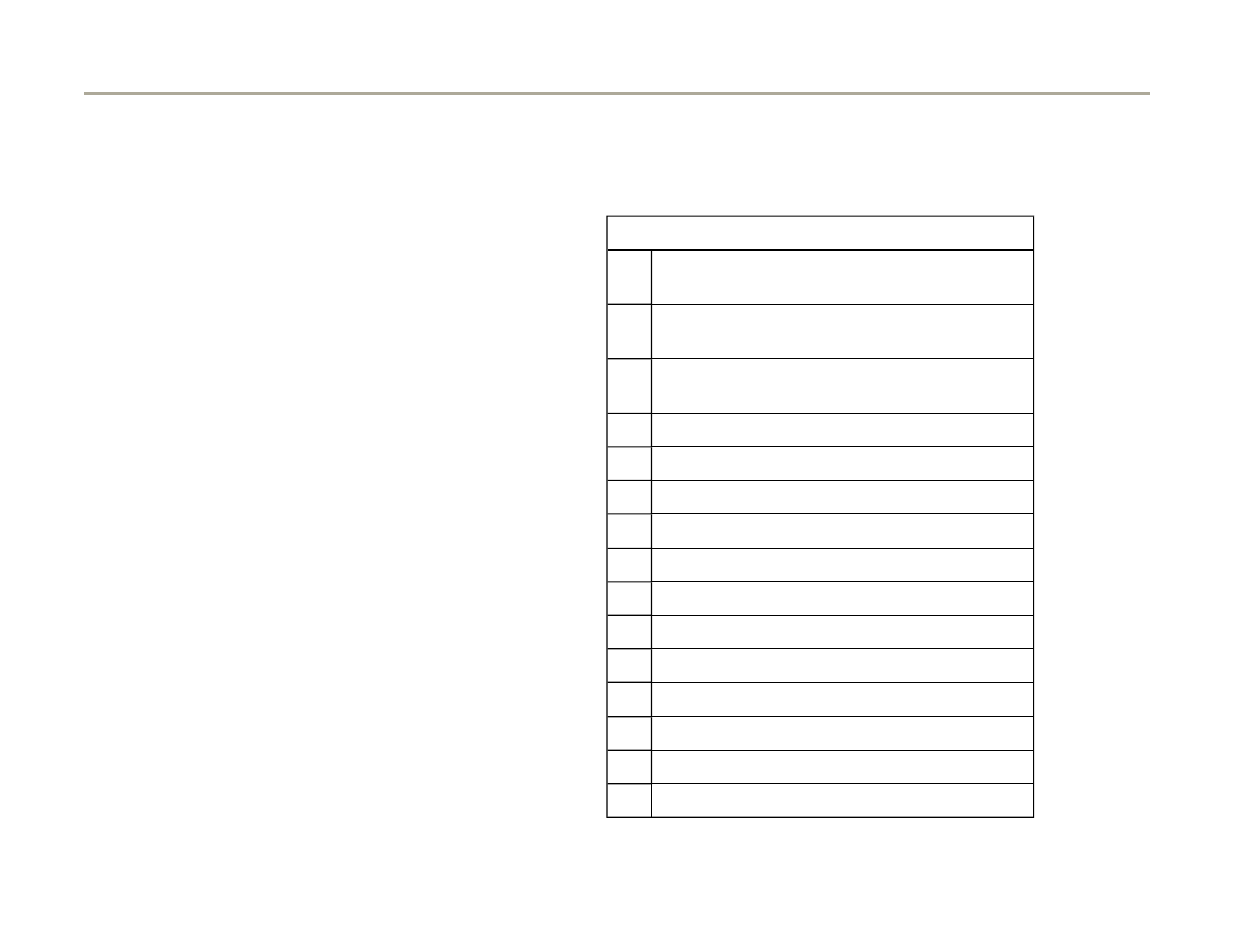
01-84
The DTM activates the following components
in the stated sequence for engine code BEL:
Activation sequence
1.
EVAP Canister Purge Regulator Valve -
N80-
2.
Secondary Air Injection (AIR) Solenoid
Valve -N112-
3.
Secondary Air Injection (AIR) Pump Relay -
J299-
4.
Wastegate Bypass Regulator Valve -N75
5.
Bank 1 Camshaft adjustment -N205-
6.
Leak Detection Pump for EVAP system
7.
Recirculating valve for turbocharger -N249
8.
Bank 2 Camshaft adjustment -N208-
9.
Vacuum pump for brake system
10. Cylinder 1 Fuel Injector -N30
11. Cylinder 4 Fuel Injector -N33
12. Cylinder 3 Fuel Injector -N32
13. Cylinder 6 Fuel Injector -N84
14. Cylinder 2 Fuel Injector -N31
15. Cylinder 5 Fuel Injector -N83
Page 110 of 183
Motronic system, On Board Diagnostic (OBD)
1/17/2006
http://127.0.0.1:8080/audi/servlet/Display?action=Goto&type=repair&id=AUDI.C5.FU03.01.1.110.11

01-85
Test requirements
Fuses for engine electronics OK
Fuel pump relay OK
- Connect vehicle diagnostic, testing and
information system VAS 5051 or VAG1551 scan
tool and select engine electronics control
module by entering address word "01"
Page
01-8
. Ignition must be switched on.
Rapid data transfer
HELP
Select function XX
Indicated on display
- Press buttons -0- and -3- to select function "Output Diagnostic Test
Mode."
Rapid data transfer
Q
03 - Output Diagnostic Test Mode
Indicated on display
Page 111 of 183
Motronic system, On Board Diagnostic (OBD)
1/17/2006
http://127.0.0.1:8080/audi/servlet/Display?action=Goto&type=repair&id=AUDI.C5.FU03.01.1.110.11

01-86
Actuating EVAP Canister Purge Regulator
Valve -N80-
- Confirm input with -Q- button.
Output Diagnostic Test Mode
EVAP canister purge regulator valve -N80
Indicated on display
If the solenoid valve is not actuated (does not click):
Solenoid valve will continue to be actuated (i.e. will click) until button
is pressed to advance program to next control element.
- Check EVAP Canister Purge Regulator Valve -N80-
Page 24-132
.
Page 112 of 183
Motronic system, On Board Diagnostic (OBD)
1/17/2006
http://127.0.0.1:8080/audi/servlet/Display?action=Goto&type=repair&id=AUDI.C5.FU03.01.1.110.11

01-87
Actuating Secondary Air Injection (AIR)
Solenoid Valve -N112-
Note:
Only vehicles with automatic transmission are
equipped with a secondary air injection system.
Vehicles with a manual transmission do not have
a secondary air injection system. For this reason,
on vehicles with a manual transmission the
following components: Secondary Air Injection
(AIR) Solenoid Valve -N112- and Secondary Air
Injection (AIR) Pump Relay -J299- will not be
displayed.
- Press button.
Output Diagnostic Test Mode
Secondary Air (AIR) Injection valve -N112
Indicated on display
If the secondary air injection valve does not click:
Repair Manual, 2.7 Liter V6 5V BiTurbo Engine Mechanical, Engine
Code(s): APB, BEL, Repair Group 26; Checking secondary air injection
valve
Solenoid valve will continue to be actuated (i.e. will click) until button
is pressed to advance program to next control element.
- Check Secondary Air Injection (AIR) Solenoid Valve -N112-.
Page 113 of 183
Motronic system, On Board Diagnostic (OBD)
1/17/2006
http://127.0.0.1:8080/audi/servlet/Display?action=Goto&type=repair&id=AUDI.C5.FU03.01.1.110.11

01-88
Actuating Secondary Air Injection (AIR) Pump
Relay -J299-
Note:
Only vehicles with automatic transmission are
equipped with a secondary air injection system.
Vehicles with a manual transmission do not have
a secondary air injection system. For this reason,
on vehicles with a manual transmission the
following component: Secondary Air Injection
(AIR) Pump Relay -J299- will not be displayed.
- Press button.
Output Diagnostic Test Mode
Secondary air pump relay -J299
Indicated on display
If the Secondary Air Injection (AIR) Pump Motor -V101- does not run at
intervals:
Repair Manual, 2.7 Liter V6 5V BiTurbo Engine Mechanical, Engine
Code(s): APB, BEL, Repair Group 26; Checking Secondary Air Injection
(AIR) Pump Relay -J299-
Secondary Air Injection (AIR) Pump Relay -J299- activates Secondary
Air Injection (AIR) Pump Motor -V101-, which runs for approx.: 1
minute at intervals.
- Check Secondary Air Injection (AIR) Pump Relay -J299.
Page 114 of 183
Motronic system, On Board Diagnostic (OBD)
1/17/2006
http://127.0.0.1:8080/audi/servlet/Display?action=Goto&type=repair&id=AUDI.C5.FU03.01.1.110.11

01-89
Activating Wastegate Bypass Regulator Valve
-N75-
- Press button.
Output Diagnostic Test Mode
Wastegate bypass regulator valve -N75
Indicated on display
If valve is not activated (does not click):
Repair Manual, 2.7 Liter V6 5V BiTurbo Engine Mechanical, Engine
Code(s): APB, BEL, Repair Group 21; Turbocharger, Checking Wastegate
Bypass Regulator Valve -N75-
Solenoid valve is activated for 1 minute (clicks), unless button is
pressed first to switch to next actuator.
Page 115 of 183
Motronic system, On Board Diagnostic (OBD)
1/17/2006
http://127.0.0.1:8080/audi/servlet/Display?action=Goto&type=repair&id=AUDI.C5.FU03.01.1.110.11

01-90
Actuating camshaft adjustment valves -N205-,
-N208-
- Press button.
Output Diagnostic Test Mode
Camshaft Adjustment
Indicated on display
If camshaft adjustment valve 1 or 2 is not activated:
Repair Manual, 2.7 Liter V6 5V BiTurbo Engine Mechanical, Engine
Code(s): APB, BEL, Repair Group 15; Camshaft adjustment, checking
camshaft adjustment valves
Camshaft adjustment valves 1 and 2 (-N205- and -N208-) will continue
to be activated (or will click) for about 1 minute.
Page 116 of 183
Motronic system, On Board Diagnostic (OBD)
1/17/2006
http://127.0.0.1:8080/audi/servlet/Display?action=Goto&type=repair&id=AUDI.C5.FU03.01.1.110.11

01-91
Actuating Leak Detection Pump (LDP) -V144-
- Press button.
Output Diagnostic Test Mode
EVAP system leak detection pump
Indicated on display
Note:
The clicking can be heard by listening in the area of the left rear wheel
housing.
If valve is not actuated (does not click):
Repair Manual, Fuel Supply System, Repair Group 20, Components of
EVAP system servicing, Checking Leak Detection Pump (LDP) -V144-
Change-over valve in LDP is activated for approximately 1 minute
(clicks), unless
button pressed to switch to next actuator.
Page 117 of 183
Motronic system, On Board Diagnostic (OBD)
1/17/2006
http://127.0.0.1:8080/audi/servlet/Display?action=Goto&type=repair&id=AUDI.C5.FU03.01.1.110.11

01-92
Activating Recirculating valve for
turbocharger -N249-
- Press button.
Output Diagnostic Test Mode
Recirculating valve for turbocharg -N249
Indicated on display
Solenoid valve is activated for 1 minute (clicks), unless
button is
pressed first to switch to next actuator.
If valve is not activated (does not click):
Repair Manual, 2.7 Liter V6 5V BiTurbo Engine Mechanical, Engine
Code(s): APB, BEL, Repair Group 21; Turbocharger, Checking
Recirculating valve for turbocharger -N249-
Page 118 of 183
Motronic system, On Board Diagnostic (OBD)
1/17/2006
http://127.0.0.1:8080/audi/servlet/Display?action=Goto&type=repair&id=AUDI.C5.FU03.01.1.110.11

01-93
Actuating fuel injectors
Note:
The fuel injectors are activated in firing order:
Cyl.1, Cyl.4, Cyl.3, Cyl.6, Cyl.2, Cyl,5.
- Press button.
Output Diagnostic Test Mode
Cylinder 1 fuel injectors -N30
Indicated on display
- Press button.
After pressing button, fuel injector must click five times.
Page 119 of 183
Motronic system, On Board Diagnostic (OBD)
1/17/2006
http://127.0.0.1:8080/audi/servlet/Display?action=Goto&type=repair&id=AUDI.C5.FU03.01.1.110.11

01-94
If the fuel injector does not click:
- Check fuel injectors
Page 24-48
.
- Press button.
Output Diagnostic Test Mode
Cylinder 4 fuel injectors -N33
Indicated on display
- Press button.
Output Diagnostic Test Mode
Cylinder 4 fuel injectors -N33
Indicated on display
If the fuel injector does not click:
After pressing button, fuel injector must click five times.
- Check fuel injectors
Page 24-48
.
Page 120 of 183
Motronic system, On Board Diagnostic (OBD)
1/17/2006
http://127.0.0.1:8080/audi/servlet/Display?action=Goto&type=repair&id=AUDI.C5.FU03.01.1.110.11
01-95
- Press button.
Output Diagnostic Test Mode
Cylinder 3 fuel injectors -N32
Indicated on display
- Press button.
Output Diagnostic Test Mode
Cylinder 3 fuel injectors -N32
Indicated on display
If the fuel injector does not click:
After pressing button, fuel injector must click five times.
- Check fuel injectors
Page 24-48
.
- Press button.
Output Diagnostic Test Mode
Cylinder 6 fuel injectors -N84
Indicated on display
- Press button.
Output Diagnostic Test Mode
Cylinder 6 fuel injectors -N84
Indicated on display
If the fuel injector does not click:
After pressing button, fuel injector must click five times.
- Check fuel injectors
Page 24-48
.
- Press button.
Page 121 of 183
Motronic system, On Board Diagnostic (OBD)
1/17/2006
http://127.0.0.1:8080/audi/servlet/Display?action=Goto&type=repair&id=AUDI.C5.FU03.01.1.110.11
01-96
Output Diagnostic Test Mode
Cylinder 2 fuel injectors -N31
Indicated on display
- Press button.
Output Diagnostic Test Mode
Cylinder 2 fuel injectors -N31
Indicated on display
If the fuel injector does not click:
After pressing button, fuel injector must click five times.
- Check fuel injectors
Page 24-48
.
- Press button.
Output Diagnostic Test Mode
Cylinder 5 fuel injectors -N83
Indicated on display
- Press button.
After pressing button, fuel injector must click five times.
Output Diagnostic Test Mode
Cylinder 5 fuel injectors -N83
Indicated on display
If the fuel injector does not click:
- Check fuel injectors
Page 24-48
.
- Press button.
Page 122 of 183
Motronic system, On Board Diagnostic (OBD)
1/17/2006
http://127.0.0.1:8080/audi/servlet/Display?action=Goto&type=repair&id=AUDI.C5.FU03.01.1.110.11

01-97
Output Diagnostic Test Mode
END
Indicated on display
- Press button.
Rapid data transfer
HELP
Select function XX
Indicated on display (function selection):
Note:
The output Diagnostic Test Mode (DTM) cannot be re-initiated until the
engine is started and the ignition switched off and then on again.
Page 123 of 183
Motronic system, On Board Diagnostic (OBD)
1/17/2006
http://127.0.0.1:8080/audi/servlet/Display?action=Goto&type=repair&id=AUDI.C5.FU03.01.1.110.11

01-98
Basic setting
With the ignition on and the engine not
running, the following operation can be
performed in the "Basic setting" mode
(function 04):
Adaptation of throttle valve control module to
ECM
Page 24-144
Vehicles with automatic transmission:
Adaptation of kick down function of accelerator
pedal position sensor to ECM
Display group
63 (
Page 24-164
)
With the engine running, the following
operations can be performed in the basic
setting mode "Function 04":
Learning process (adaptation) for oxygen
sensor control
every Display group
Troubleshooting by targeted activation and
deactivation of oxygen sensor control
Display group 99 (Observe note on
Page 24-
78
).
Page 124 of 183
Motronic system, On Board Diagnostic (OBD)
1/17/2006
http://127.0.0.1:8080/audi/servlet/Display?action=Goto&type=repair&id=AUDI.C5.FU03.01.1.110.11

01-99
Test requirements for operations with engine
running
No DTCs stored in DTC memory
Coolant temperature at least 80 C
Electrical consumers switched off (coolant
fan must not run during test)
A/C switched off
- Connect vehicle diagnostic, testing and
information system VAS 5051 or VAG1551 scan
tool and select engine electronics control
module by entering address word "01"
Page
01-8
. Engine must be idling.
- Check and erase DTC memory
Page 01-14
.
There should be no malfunctions stored in DTC
memory. (If necessary, repair malfunctions,
erase DTC memory and switch off engine. Start
engine again, road test vehicle and check DTC
memory again).
- Continue to run engine at idle.
Rapid data transfer
HELP
Indicated on display
Page 125 of 183
Motronic system, On Board Diagnostic (OBD)
1/17/2006
http://127.0.0.1:8080/audi/servlet/Display?action=Goto&type=repair&id=AUDI.C5.FU03.01.1.110.11

Select function XX
Page 126 of 183
Motronic system, On Board Diagnostic (OBD)
1/17/2006
http://127.0.0.1:8080/audi/servlet/Display?action=Goto&type=repair&id=AUDI.C5.FU03.01.1.110.11

01-100
- Press buttons -0- and -4- to select function
"Basic Setting"
System in Basic Setting
04 - Basic Setting
Indicated on display
- Confirm entry by pressing -Q- button.
System in Basic Setting
Input display group number XXX
Indicated on display
Note:
Display Group 000 is used here as an example to illustrate the procedure.
(000 is to select Display Group 000)
Note:
When the display group is selected the EVAP valve is closed and the air
conditioner compressor is switched off.
- Press buttons -0- three times.
System in Basic Setting
Q
Input display group number
000
Indicated on display
- Confirm entry by pressing -Q- button.
System in basic setting 0
1
2
3
4
5
6
7
8
9
10
Indicated on display
Page 127 of 183
Motronic system, On Board Diagnostic (OBD)
1/17/2006
http://127.0.0.1:8080/audi/servlet/Display?action=Goto&type=repair&id=AUDI.C5.FU03.01.1.110.11
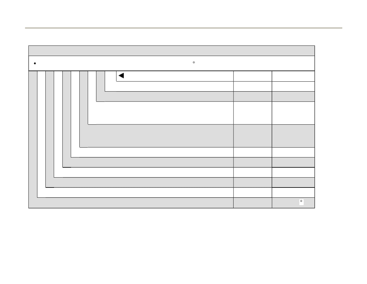
01-101
Display group 000 (indicated values decimal)
Engine running at idle (Coolant Temperature not less than 80 C)
1 2 3 4 5 6 7 8 9 10
Display fields
Specification
Represents
Adaptation value of mixture formation, bank 2
108 - 148
-4 to 4%
Adaptation value of mixture formation, bank 1
108 - 148
-4 to 4%
Control value of mixture formation bank 2
(If out of specification perform road test)
122 - 136
-4 to 4%
Control value of mixture formation bank 2
(If out of specification perform road test)
122 - 136
-4 to 4%
Adaptation value torque loss at idle
124 - 140
-3 to 5%
Idle torque
126 - 135
-1.5 to 1.5%
Throttle valve angle
1 - 7
0.4 to 2.75%
Engine speed (idle speed)
67 - 73
650 - 750 RPM
Engine load (without consumers)
21 - 34
15 - 26%
Engine Coolant Temperature (requirement for basic setting)
177 - 203
85 - 105 C
1)
Up-to-date specifications:
Page 128 of 183
Motronic system, On Board Diagnostic (OBD)
1/17/2006
http://127.0.0.1:8080/audi/servlet/Display?action=Goto&type=repair&id=AUDI.C5.FU03.01.1.110.11

01-102
- Allow engine to idle for a few minutes: Coolant
temperature at least 80 C.
Note:
When the PRINT button is pressed the current
display will be printed out.
Press C button before selecting further display
groups.
- If readouts in all display fields match
specifications, press
button.
Rapid data transfer
HELP
Select function XX
Indicated on display
- Press buttons -0- and -6- to select function "End Output".
Rapid data transfer
HELP
06 - End Output
Indicated on display
- Confirm with -Q- button.
Rapid data transfer
HELP
Select function XX
Indicated on display
Page 129 of 183
Motronic system, On Board Diagnostic (OBD)
1/17/2006
http://127.0.0.1:8080/audi/servlet/Display?action=Goto&type=repair&id=AUDI.C5.FU03.01.1.110.11

01-103
Control module, coding
Note:
If the correct coding for the vehicle is not
displayed, or if the control module has been
replaced, the control module must be coded.
The code table is valid for current chassis forms
of the Audi A6 as well as for the off-road
version "Allroad".
- Connect vehicle diagnostic, testing and
information system VAS 5051 or VAG1551 scan
tool and select engine electronics control
module by entering address word "01"
Page
01-8
. Ignition must be switched on.
4B0907551.. 2.7 L V6/5VT G 0002
Coding 06612
WSC 06388
The display of VAG1551 will show the control module coding (example).
The relevant vehicle coding must be displayed, note coding table
Page
01-104
.
Page 130 of 183
Motronic system, On Board Diagnostic (OBD)
1/17/2006
http://127.0.0.1:8080/audi/servlet/Display?action=Goto&type=repair&id=AUDI.C5.FU03.01.1.110.11

01-104
Coding variations of Engine Control Module (ECM) for vehicles with engine code APB. Coding variations for vehicles
with engine code BEL
Page 01-105
Country/
Emission standard
Power train /
Additional systems
Transmission
Type of
vehicle
00 = ------------------
0 = ------------------
0 = ------------------
0 = ----------
--------
01 = ------------------
1 = ------------------
1 = 6-speed manual
transmission
1 = ----------
--------
02 = ------------------
2 = ------------------
2 = ------------------
2 = Audi
A6
03 = ------------------
3 = ------------------
3 = ------------------
3 = ----------
--------
04 = ------------------
4 = ------------------
4 = ------------------
4 = ----------
--------
05 = -------------------
5 = ------------------
5 = 5-speed automatic
transmission 01V
(5HP19)
5 = ----------
--------
06 = USA; TLEV (Exhaust emission
standard) NOTE: Vehicles with
Leak Detection Pump (LDP)
6 = All-wheel drive without Anti Slip
Regulation (ASR)/Electronic Stability
Program (ESP) (with CAN-Bus system)
6 = ------------------
6 = ----------
--------
07 = -----------------
7 = All-wheel drive with Anti Slip Regulation
(ASR)/Electronic Stability Program (ESP)
(with CAN-Bus system)
7 = ------------------
7 = ----------
--------
08 = -----------------
08 = Audi Allroad vehicles with post-switch
stage (low range)
08 = -----------------
08 = --------
----------
Page 131 of 183
Motronic system, On Board Diagnostic (OBD)
1/17/2006
http://127.0.0.1:8080/audi/servlet/Display?action=Goto&type=repair&id=AUDI.C5.FU03.01.1.110.11

01-105
Coding variations of Engine Control Module (ECM) for vehicles with engine code BEL. Coding variations for vehicles
with engine code APB
Page 01-104
Country/
Emission standard
Power train /
Additional systems
Transmission
Type of
vehicle
00 = ------------------
0 = ------------------
0 = ------------------
0 = ---------
---------
01 = ------------------
1 = ------------------
1 = 6-speed manual
transmission
1 = ---------
---------
02 = ------------------
2 = ------------------
2 = ------------------
2 = Audi
A6
03 = ------------------
3 = ------------------
3 = ------------------
3 = ---------
---------
04 = ------------------
4 = ------------------
4 = ------------------
4 = ---------
---------
05 = -------------------
5 = ------------------
5 = 5-speed automatic
transmission 01V
(5HP19)
5 = Audi
allroad
06 = -------------------
6 = ------------------
6 = ------------------
6 = ---------
---------
07 = USA; LEV (Exhaust emission
standard) NOTE: Vehicles with Leak
Detection Pump (LDP)
7 = All-wheel drive with Anti Slip Regulation
(ASR)/Electronic Stability Program (ESP)
(with CAN-Bus system)
7 = ------------------
7 = ---------
---------
Page 132 of 183
Motronic system, On Board Diagnostic (OBD)
1/17/2006
http://127.0.0.1:8080/audi/servlet/Display?action=Goto&type=repair&id=AUDI.C5.FU03.01.1.110.11

01-106
Notes:
TLEV = Transient Low Emission Vehicles. ESP = Electronic Stability Program
If the vehicle is equipped with ESP it can be identified at the ESP switch in the instrument cluster.
Anti Slip Regulation is often abbreviated as "ASR". Electronic Stability Program is abbreviated as "ESP".
Audi allroad vehicles are always equipped with ESP. On the third digit of the control module coding the Engine Control
Module (ECM) is informed about whether a post-switch stage (low range) is installed (characteristic: Switch for post-switch
stage at shift handle). This differentiation is required on vehicles with manual transmission. Allroad vehicles with automatic
transmission never have a post-switch stage.
For standard Audi A6, notes regarding post-switch stage (also in code table) can be disregarded.
Indicated code number consists of the following
(example):
TLEV (exhaust norm)
06
All wheel drive without Electronic
Stability Program (ESP)
6
6-speed manual transmission
1
Audi A6
2
Code number
06 6 1 2
Note:
Page 133 of 183
Motronic system, On Board Diagnostic (OBD)
1/17/2006
http://127.0.0.1:8080/audi/servlet/Display?action=Goto&type=repair&id=AUDI.C5.FU03.01.1.110.11

TLEV = Transient Low Emission Vehicles. ESP =
Electronic Stability Program
Page 134 of 183
Motronic system, On Board Diagnostic (OBD)
1/17/2006
http://127.0.0.1:8080/audi/servlet/Display?action=Goto&type=repair&id=AUDI.C5.FU03.01.1.110.11

01-107
If an incorrect coding is displayed:
- Press button.
Rapid data transfer
HELP
Select function XX
When indicated on display
- Press buttons "07" for the function "Code Control Module" and press Q
button to confirm input.
Code Control Module
Q
Input code number XXXXX
(0-32000)
When indicated on display
- Input control module coding according to coding table and press -Q-
button to confirm input
Page 01-104
.
Function unknown or
.
cannot be carried out currently
If this message appears
following Note:
Note:
Check in parts catalog whether the correct control module has been
installed (part number; possibly the control module cannot be coded). It
also possible that an incorrect code number was entered. If necessary
repeat coding.
- Press button.
Rapid data transfer
HELP
Select function XX
Indicated on display
- Press buttons -0- and -6- to select function "End Output" and confirm
entry with -Q- button.
Page 135 of 183
Motronic system, On Board Diagnostic (OBD)
1/17/2006
http://127.0.0.1:8080/audi/servlet/Display?action=Goto&type=repair&id=AUDI.C5.FU03.01.1.110.11

01-108
Read Measuring Value Block
Test requirements
Coolant temperature at least 80 C
Electrical consumers switched off (coolant
fan must not run during the check)
A/C switched off
- Connect vehicle diagnostic, testing and
information system VAS 5051 or VAG1551 scan
tool and select engine electronics control
module by entering address word "01"
Page
01-8
. Engine must be idling.
Rapid data transfer
HELP
Select function XX
Indicated on display:
- Press buttons -0- and -8- to select function "Read Measuring Value
Block" and confirm entry with -Q- button.
Read Measuring Value Block
Input display group number XXX
Indicated on display
Page 136 of 183
Motronic system, On Board Diagnostic (OBD)
1/17/2006
http://127.0.0.1:8080/audi/servlet/Display?action=Goto&type=repair&id=AUDI.C5.FU03.01.1.110.11
01-109
- Input relevant Display Group number (3 figures)
and confirm entry by pressing -Q- button.
Note:
The display group number required is indicated
in the instructions for testing functions and
components given in the relevant sections of this
Manual.
Read Measuring Value Block 0
1
2
3
4
5
6
7
8
9
10
Indicated on display for display group 000:
Note:
To change to another display group proceed as follows:
Display group VAG1551 scan tool
VAS5051
tester
Higher
Press button 3
Press
button
Lower
Press button 1
Press
button
Page 137 of 183
Motronic system, On Board Diagnostic (OBD)
1/17/2006
http://127.0.0.1:8080/audi/servlet/Display?action=Goto&type=repair&id=AUDI.C5.FU03.01.1.110.11

01-110
Readiness code
The readiness code is an 8 digit display in
measuring value block 086, display field 1. Each
of the 8 digits is assigned to a specific exhaust
related system.
If the function of these systems is checked via a
test by the On Board Diagnostic (OBD), which is
successfully completed, then the position
assigned to this system will be switched from "1"
to "0." This occurs regardless of whether the test
is indicated as "OK" or "not OK" as long as the
test is successfully completed.
If a test is completed, but indicated as "not OK",
a DTC will be stored in the DTC memory. Check
DTC memory
Page 01-14
.
When the readiness code is generated after a
successfully completed test, "00000000" will be
displayed. (Measuring value block 086, display
field 1).
Page 138 of 183
Motronic system, On Board Diagnostic (OBD)
1/17/2006
http://127.0.0.1:8080/audi/servlet/Display?action=Goto&type=repair&id=AUDI.C5.FU03.01.1.110.11

01-111
The readiness code will be reset to "1 1 1 1 1
1 1 1" if:
The DTC memory was erased
A new Engine Control Module was installed
If the voltage supply has been disconnected
from the Engine Control Module (ECM)
In this case the readiness code must be
generated
Page 01-116
.
During driving operation in various load
conditions, exhaust relevant tests are performed
by the control module within a "short trip" and the
readiness code is generated on its own. In this
case, however, concluding control possibilities
are not available, meaning that it will not be
indicated whether all positions of the readiness
code are set to "0."
Page 139 of 183
Motronic system, On Board Diagnostic (OBD)
1/17/2006
http://127.0.0.1:8080/audi/servlet/Display?action=Goto&type=repair&id=AUDI.C5.FU03.01.1.110.11

01-112
Readiness code, checking
Test sequence
- Connect vehicle diagnostic, testing and
information system VAS5051 or VAG1551 scan
tool to vehicle and select Control module for
engine electronics "Address Word" 01
Page
01-8
. Ignition must be switched on.
Rapid data transfer
HELP
Select function XX
When indicated on display
- Press buttons -0- and -8- to select "Read Measuring Value Block" and
press -Q- button to confirm input.
Read Measuring Value Block
Q
Input display group number XXX
When indicated on display
- Press buttons -0-, -8- and -6- for "display group number 086" and press
-Q- button to confirm input.
Read Measuring Value Block 86
1
2
3
4
When indicated on display
- Check readiness code in display field 1
Specified value: 0 0 0 0 0 0 0 0
Page 140 of 183
Motronic system, On Board Diagnostic (OBD)
1/17/2006
http://127.0.0.1:8080/audi/servlet/Display?action=Goto&type=repair&id=AUDI.C5.FU03.01.1.110.11
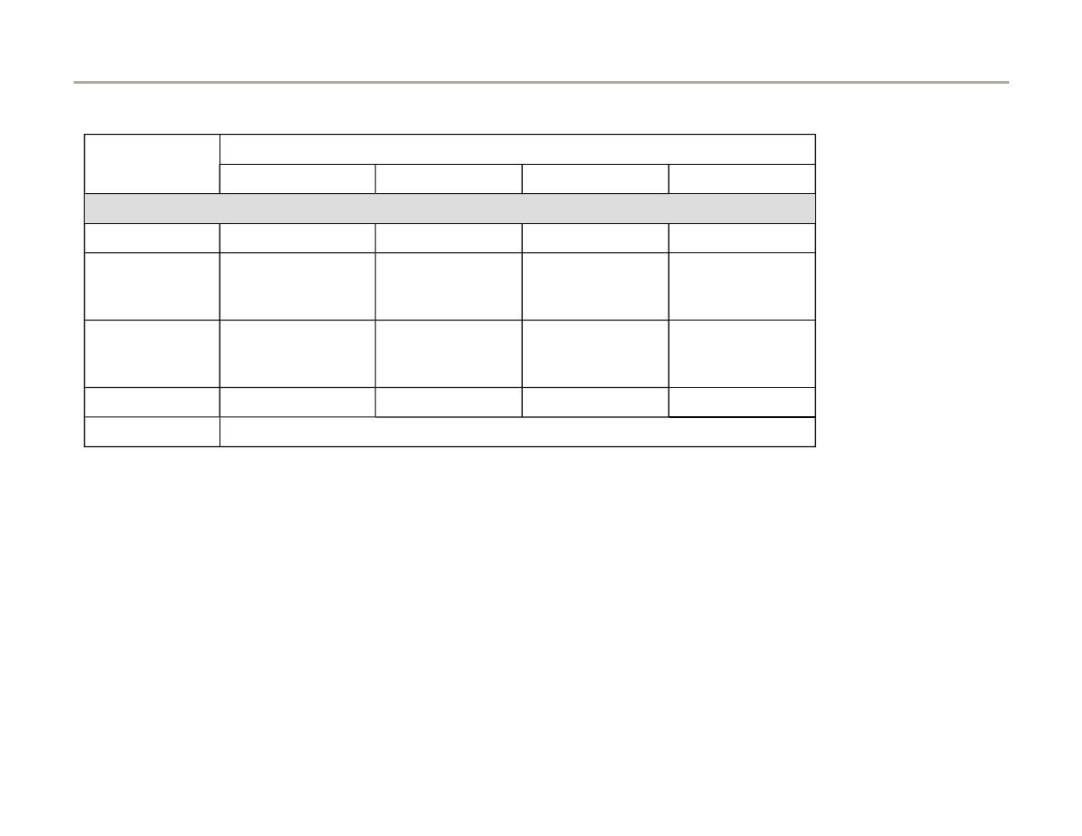
01-113
Display fields
1
2
3
4
Display Group 086: Readiness code
Display
0 0 0 0 0 0 0 0
X X X X X X X X
X X X X X X X X
X X X X X X X X
Indicated
Ready-Bits
completed tests
Cycle-Flags
Performed cycles
Cycle-Flags
Performed cycles
Cycle-Flags
Performed cycles
Work area
1 = not completed
0 = completed
1 = not completed
0 = completed
1 = not completed
0 = completed
1 = not completed
0 = completed
Specified value
0 0 0 0 0 0 0 0
X X X X X X X X
X X X X X X X X
X X X X X X X X
Note:
Readiness code significance on next pages
Note for display field 1:
This display field indicates which diagnosis was checked last after the DTC memory was erased or if the control module was
replaced. After erasing the DTC memory, all values that can be checked will be reset to 1. After successful testing these
values will be reset to 0.
Page 141 of 183
Motronic system, On Board Diagnostic (OBD)
1/17/2006
http://127.0.0.1:8080/audi/servlet/Display?action=Goto&type=repair&id=AUDI.C5.FU03.01.1.110.11
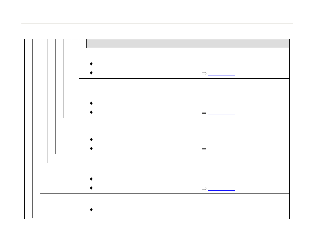
01-114
X X X X X X X X
Notes for display group 086 display field 1 (Ready-Bits)
1 = Three Way Catalytic Converter (TWC) (diagnostic of catalytic converter)
Display 0 = ready
Display 1 = not ready (Readiness code generating
Page 01-116
)
2 = TWC Catalytic Converter (not available/always "0")
3 = EVAP system (0 = ready)
Display 0 = ready
Display 1 = not ready (Readiness code generating
Page 01-116
)
4 = Secondary Air Injection (AIR) System (only on vehicles with automatic transmission, on
vehicles with manual transmission this digit is always "0")
Display 0 = ready
Display 1 = not ready (Readiness code generating
Page 01-116
)
5 = Climate Control (diagnosis not applicable/always "0")
6 = Oxygen sensors
Display 0 = ready
Display 1 = not ready (Readiness code generating
Page 01-116
)
7 = Oxygen sensor (O2S) heater
Display 0 = ready
Page 142 of 183
Motronic system, On Board Diagnostic (OBD)
1/17/2006
http://127.0.0.1:8080/audi/servlet/Display?action=Goto&type=repair&id=AUDI.C5.FU03.01.1.110.11

Display 1 = not ready
8 = Exhaust Gas Recirculation (EGR) system (not applicable/always "0")
Note:
The readiness code is only set if all position are displayed with "0."
Page 143 of 183
Motronic system, On Board Diagnostic (OBD)
1/17/2006
http://127.0.0.1:8080/audi/servlet/Display?action=Goto&type=repair&id=AUDI.C5.FU03.01.1.110.11

01-115
If the specified value in display field 1:
"00000000" is obtained:
- Press button.
Rapid data transfer
HELP
Select function XX
Indicated on display (function selection)
If specified value is not reached:
- Check DTC memory
Page 01-14
(No malfunction should be stored
in DTC memory).
- Generate readiness code
Page 01-116
.
Page 144 of 183
Motronic system, On Board Diagnostic (OBD)
1/17/2006
http://127.0.0.1:8080/audi/servlet/Display?action=Goto&type=repair&id=AUDI.C5.FU03.01.1.110.11
01-116
Readiness code, generating
Required special tools and test equipment
Requirements
Note:
In some procedures you are asked to set a higher RPM with the V.A.G
1788/10 RPM adjuster. If the engine does not accept a higher RPM for
specific display groups, fully engage the accelerator and brake pedals
simultaneously. The engine will then reach a specifically defined RPM on
its own.
VAG1788/10 RPM adjuster
Electrical consumers switched off (coolant fan must NOT run during
test)
Coolant temperature min. 80 C (185 F)
Page 145 of 183
Motronic system, On Board Diagnostic (OBD)
1/17/2006
http://127.0.0.1:8080/audi/servlet/Display?action=Goto&type=repair&id=AUDI.C5.FU03.01.1.110.11

01-117
Work step 1: Check DTC memory
- Connect Vehicle Diagnostic, Test and
Information system VAS5051 or VAG1551 scan
tool to vehicle and select control module for
engine electronics using "address word" 01
Page 01-8
. Ignition is switched on.
Rapid data transfer
HELP
Select function XX
When indicated on display
- Press buttons -0- and -2- to select function "Check DTC Memory" and
press -Q- button to confirm input.
X DTC recognized!
Number of stored DTCs or "No DTC recognized" will be indicated on
display.
If a DTC is stored:
If no DTC is stored:
- Repair malfunction, erase DTC memory. Road test vehicle and then re-
check DTC memory as a control measure.
- Press button.
Page 146 of 183
Motronic system, On Board Diagnostic (OBD)
1/17/2006
http://127.0.0.1:8080/audi/servlet/Display?action=Goto&type=repair&id=AUDI.C5.FU03.01.1.110.11

01-118
Work step 2: Erase DTC Memory
Test requirements
Ignition switched on
Rapid data transfer
HELP
Select function XX
When indicated on display
Note:
When DTC memory is erased, readiness code is reset and must therefore
be regenerated.
- Press button -0- and -5- to select function "Erase DTC Memory" and
press -Q- button to confirm input.
Rapid data transfer
DTC memory is erased
When indicated on display
- Press button.
Page 147 of 183
Motronic system, On Board Diagnostic (OBD)
1/17/2006
http://127.0.0.1:8080/audi/servlet/Display?action=Goto&type=repair&id=AUDI.C5.FU03.01.1.110.11

01-119
Work step 3: Adaptation Throttle Valve
Control Module to Engine Control Module
(ECM)
Test requirements
Ignition switched on.
Rapid data transfer
HELP
Select function XX
When indicated on display
- Press buttons "04" for the function "Basic Setting" and press -Q- button
to confirm input.
System in Basic Setting
Q
Input display group number XXX
When indicated on display
- Input "060" for "display group number 60" and press -Q- button to
confirm input.
System in Basic Setting 60
1
2
3
4
When indicated on display
- Check readiness code in display field 3 and 4:
Page 148 of 183
Motronic system, On Board Diagnostic (OBD)
1/17/2006
http://127.0.0.1:8080/audi/servlet/Display?action=Goto&type=repair&id=AUDI.C5.FU03.01.1.110.11
01-120
Display fields
1
2
3
4
Display group 060: Adaptation of throttle valve control module
Display
xx %
xx %
x
---
Indicated
Throttle
valve angle
(angle
sensor 1)
Throttle
valve angle
(angle
sensor 2)
Adaptation step counter
Adaptation condition
Work area
0 - 100 %
100 - 0 %
0 - 8
ADP. runs
ADP. OK
ADP. ERROR
Specified
value
3 - 93 %
97 - 3 %
8
ADP. OK
Note:
During adaptation, adaptation step counter
must reach the number 8. (Some numbers
may be skipped).
If "ADP. ERROR." is displayed:
Check DTC memory
Page
01-14
.
If specified value is not
obtained:
Note,
Page 24-
150
.
Note for display field 3:
During adaptation different digits are displayed in display field 3, which indicate the particular adaptation condition. It is not
important what the adaptation step counter (display field 3) displays during adaptation, rather that display field 4 displays the
Page 149 of 183
Motronic system, On Board Diagnostic (OBD)
1/17/2006
http://127.0.0.1:8080/audi/servlet/Display?action=Goto&type=repair&id=AUDI.C5.FU03.01.1.110.11

specification value "ADP. OK.
If specified value "ADP. OK" is obtained:
- Press -C- button.
Page 150 of 183
Motronic system, On Board Diagnostic (OBD)
1/17/2006
http://127.0.0.1:8080/audi/servlet/Display?action=Goto&type=repair&id=AUDI.C5.FU03.01.1.110.11

01-121
Work step 4: Diagnosis of EVAP canister
purge regulator valve
- Start engine (vehicles with manual transmission
depress clutch pedal)
Note:
If necessary, ECM must be re-selected with the
"address word" 01 following engine start, and the
function "initiate basic setting" selected with "04."
Test requirements
Engine at idle
Coolant temperature greater than 85 C
(display group 4, display field 3)
Rapid data transfer
HELP
Select function XX
Indicated on display
- Press buttons -0-, -7- and -0- to select "display group 070" and confirm
input with -Q- button.
System in Basic Setting 70
1
2
3
4
When indicated on display
Note:
- Check specified value in display field 4:
Page 151 of 183
Motronic system, On Board Diagnostic (OBD)
1/17/2006
http://127.0.0.1:8080/audi/servlet/Display?action=Goto&type=repair&id=AUDI.C5.FU03.01.1.110.11

If test is not initiated or the display jumps from "Test ON" to "Test OFF"
slightly accelerate engine briefly, test will be repeated.
Page 152 of 183
Motronic system, On Board Diagnostic (OBD)
1/17/2006
http://127.0.0.1:8080/audi/servlet/Display?action=Goto&type=repair&id=AUDI.C5.FU03.01.1.110.11
01-122
Display fields
1
2
3
4
Display group 070: Diagnostic of EVAP canister purge regulator valve
Display
xx %
xx.x %
xx %
Test ON
Indicated
EVAP valve duty
cycle during
diagnosis
Oxygen sensor
control deviation
during diagnosis
Relative
Ground via
EVAP valve
Diagnostic condition
Work
Range
min.: 0 %
max.: 100 %
min.: -25.0 %
max.: 25.0 %
Test OFF
Test ON
EVAP OK
EVAP n.OK
Abort
Specified
value
xx %
-5.0 to 4.0 %
xx - xx %
1)
EVAP OK
Note:
If "EVAP n. OK" is displayed: Check DTC
memory
Page 01-14
. Check EVAP canister
purge regulator valve -N80-
Page 24-132
1)
A display appears only if the diagnostic result occurred via deviation from the Idle Air Control (IAC) in a specified tolerance
range and not from deviation from the oxygen sensor control (e.g.: oxygen sensor 1 from EVAP canister). Display field 3 is
only indicated if there is a deviation.
If the specified value "EVAP OK" is reached:
Page 153 of 183
Motronic system, On Board Diagnostic (OBD)
1/17/2006
http://127.0.0.1:8080/audi/servlet/Display?action=Goto&type=repair&id=AUDI.C5.FU03.01.1.110.11

- Press -C- button
Page 154 of 183
Motronic system, On Board Diagnostic (OBD)
1/17/2006
http://127.0.0.1:8080/audi/servlet/Display?action=Goto&type=repair&id=AUDI.C5.FU03.01.1.110.11

01-123
Work step 5: Diagnosis of tank leak test
Note:
This diagnostic is locked the first 230 seconds
after engine is started.
Test requirements
Engine at idle
Coolant temperature greater 85 C (Display
group 4, display field 3)
Intake air temperature less 95 C (Display
group 4, display field 4)
System in Basic System
Q
Input display group number XXX
When indicated on display
- Press buttons -0-, -7- and -1- to select "display group 071" and press -
Q- button to confirm input.
Page 155 of 183
Motronic system, On Board Diagnostic (OBD)
1/17/2006
http://127.0.0.1:8080/audi/servlet/Display?action=Goto&type=repair&id=AUDI.C5.FU03.01.1.110.11

01-124
System in Basic Setting 71
1
2
3
4
When indicated on display
During test "Test ON" displayed in display field 4. Continue to hold test
conditions until a diagnostic result is displayed in display field 4.
Note:
- Check specified value in display field 4:
Test duration for tank leak test takes approximately 60 seconds.
Should the diagnosis be repeated several times, open fuel filler cap
each time to release pressure in tank.
Page 156 of 183
Motronic system, On Board Diagnostic (OBD)
1/17/2006
http://127.0.0.1:8080/audi/servlet/Display?action=Goto&type=repair&id=AUDI.C5.FU03.01.1.110.11
01-125
Display fields
1
2
3
4
Display group 071: Diagnostic of tank leak test
Display
Reed open
---
System Test
Test ON
Indicated
Condition Reed-
contact
malfunction
message
System
condition
Diagnostic condition and Diagnostic result
Work range
Reed open
Reed closed
Small leak
Large leak
Syst. not OK
System Test
Measurement
Measurement
END
Test OFF
Test ON
Syst. OK
Syst. not OK
Abort
Specified
value
Reed open
---
Measurement
END
Syst. OK
Note
If "Syst. not OK" is displayed: Check DTC
memory
Page 01-14
.
If specified value in display field "System OK" is
reached:
- Press -C- button.
Page 157 of 183
Motronic system, On Board Diagnostic (OBD)
1/17/2006
http://127.0.0.1:8080/audi/servlet/Display?action=Goto&type=repair&id=AUDI.C5.FU03.01.1.110.11

01-126
Work step 6: Diagnosis of fuel supply system
Test requirements
Engine at idle
Oxygen sensor control active
System in Basic System
Q
Input display group number XXX
When indicated on display
- Press buttons -1-, -0- and -7- to select "display group 107" and confirm
with -Q- button.
System in Basic Setting 107
1
2
3
4
When indicated on display
Note:
- Check specified values in display field 4.
If display "Test ON" does not appear in the display field, switch the
engine off, restart and repeat work step 6. (Diagnostic of fuel supply
system)
After the engine has been restarted it might be necessary to select
"Address word 01" and initiate the function "04 Basic Setting" again.
Page 158 of 183
Motronic system, On Board Diagnostic (OBD)
1/17/2006
http://127.0.0.1:8080/audi/servlet/Display?action=Goto&type=repair&id=AUDI.C5.FU03.01.1.110.11
01-127
Display fields
1
2
3
4
Display group 107: Diagnostic of fuel supply
Display
xxx /RPM
x.x %
x.x %
Test ON
Indicated
Engine speed
(actual)
Oxygen sensor control
average value (Bank 1)
Oxygen sensor control
average value (Bank 2)
Diagnostic condition
Work
range
min.: 650 RPM
max.: 6800
RPM
min.: -25.0 %
max.: 25.0 %
min.: -25.0 %
max.: 25.0 %
Test OFF
Test ON
Syst. OK
Syst. n OK
Value
650 - 750 RPM
-18.0 % to 12.0 %
-18.0 % to 12.0 %
Syst. OK
Note
If "Syst. n OK" appears, check
DTC memory
Page 01-14
.
If specified value in display "System OK" is
reached:
- Press -C- button.
Page 159 of 183
Motronic system, On Board Diagnostic (OBD)
1/17/2006
http://127.0.0.1:8080/audi/servlet/Display?action=Goto&type=repair&id=AUDI.C5.FU03.01.1.110.11

01-128
Work step 7: Diagnosis of oxygen sensor
heater
System in Basic Setting
Q
Input display group number XXX
When indicated on display
- Press buttons -0-, -4- and -1- to select "display group 041" and confirm
with -Q- button.
System in Basic Setting 41
1
2
3
4
When indicated on display
Note:
Increasing engine speed accelerates the obtaining of specified values.
- Check specified value in display field 1 and 3:
Page 160 of 183
Motronic system, On Board Diagnostic (OBD)
1/17/2006
http://127.0.0.1:8080/audi/servlet/Display?action=Goto&type=repair&id=AUDI.C5.FU03.01.1.110.11
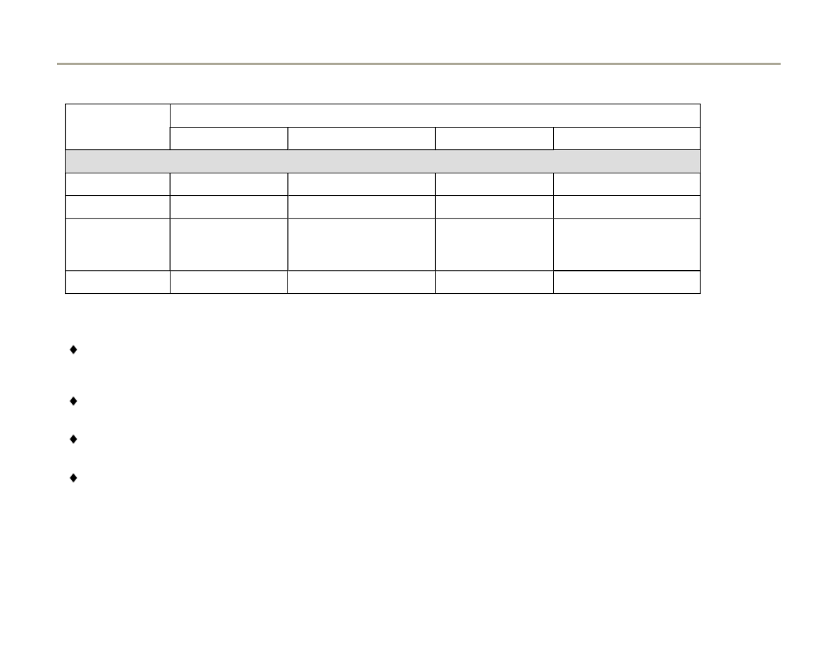
01-129
Display fields
1
2
3
4
Display group 041: Oxygen sensor heater, bank 1
Display
xxx kOhm
Heater before CAT ON
xxx kOhm
Heater after CAT ON
Indicated
Bank 1, Sensor 1
Condition of heater
Bank 1, Sensor 2
Condition of heater
Work range
Heater b. CAT ON
Heater b. TWC OFF
Heater a. CAT ON
Heater a. CAT OFF
Specified value
0 - 0.5 kOhm
Heater b. CAT ON/OFF
0 - 0.5 kOhm
Heater a. CAT ON/OFF
Important note for display fields 1,2,3 and 4:
Display fields 1 and 3 will not indicate any value if the operating temperature of the oxygen sensors is not reached, in
which case both fields are empty. (Increase Engine Speed to reach specified value).
After the operating temperature is reached, the display fields 1 and 3 must display a value of less than 0.5k Ohm
Only proceed with test after value of less than 0.5k Ohm is displayed with in display fields 1 and 3.
The Engine Control Module (ECM) cycles the oxygen sensor heating at certain operating conditions. This means the
heater is under certain operating conditions ON or OFF. It is therefore possible that the specification in display field 2 and
4 appears periodically as "Heater b. CAT OFF" or "Heater a. CAT OFF"
- Press -C- button.
Page 161 of 183
Motronic system, On Board Diagnostic (OBD)
1/17/2006
http://127.0.0.1:8080/audi/servlet/Display?action=Goto&type=repair&id=AUDI.C5.FU03.01.1.110.11

- Press buttons -0-, -4- and -2- to select "display
group 042" and confirm input with -Q- button.
Page 162 of 183
Motronic system, On Board Diagnostic (OBD)
1/17/2006
http://127.0.0.1:8080/audi/servlet/Display?action=Goto&type=repair&id=AUDI.C5.FU03.01.1.110.11
01-130
Display fields
1
2
3
4
Display group 042: Oxygen sensor heater, bank 1
Display
xxx kOhm
Heater before CAT ON
xxx kOhm
Heater after CAT ON
Indicated
Bank 1, Sensor 1
Condition of heater
Bank 1, Sensor 2
Condition of heater
Work range
Heater b. CAT ON
Heater b. TWC OFF
Heater a. CAT ON
Heater a. CAT OFF
Specified value
0 - 0.5 kOhm
Heater b. CAT ON/OFF
0 - 0.5 kOhm
Heater a. CAT ON/OFF
Note
Observe note below
Observe note below
Important note for display fields 1,2,3 and 4:
Display fields 1 and 3 will not indicate any value if the operating temperature of the oxygen sensors is not reached, in
which case both fields are empty. (Increase Engine Speed to reach specified value).
After the operating temperature is reached, the display fields 1 and 3 must display a value of less than 0.5k Ohm
Only proceed with test after value of less than 0.5k Ohm is displayed with in display fields 1 and 3.
The Engine Control Module (ECM) cycles the oxygen sensor heater at certain operating conditions. This means the heater
is under certain operating conditions ON or OFF. It is therefore possible that the specification in display field 2 and 4
appears periodically as "Heater b. CAT OFF" or "Heater a. CAT OFF"
- Press -C- button.
Page 163 of 183
Motronic system, On Board Diagnostic (OBD)
1/17/2006
http://127.0.0.1:8080/audi/servlet/Display?action=Goto&type=repair&id=AUDI.C5.FU03.01.1.110.11

01-131
Work step 8: Diagnosis of oxygen sensor
aging before catalytic converter
Test requirements
Engine running at 1900 - 2200 RPM
System in Basic Setting
Q
Input display group number XXX
Indicated on display
- Press buttons -0-, -3- and -4- to select "display group 034" and confirm
with -Q- button.
System in Basic Setting 34
1
2
3
4
Indicated on display
- Check specified value in display field 4:
Page 164 of 183
Motronic system, On Board Diagnostic (OBD)
1/17/2006
http://127.0.0.1:8080/audi/servlet/Display?action=Goto&type=repair&id=AUDI.C5.FU03.01.1.110.11
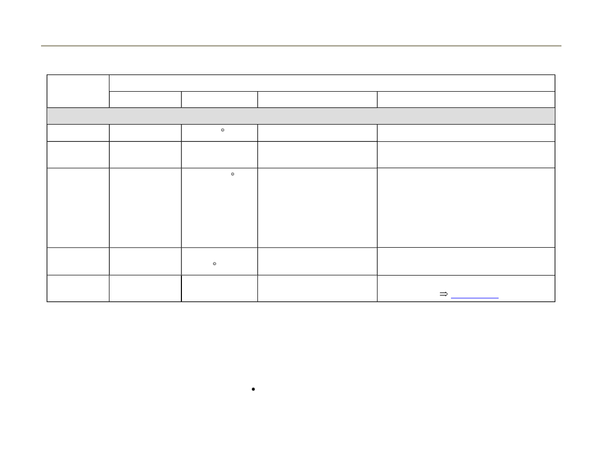
01-132
Display fields
1
2
3
4
Display group 034: Oxygen sensor aging before catalytic converter (Bank 1)
Display
xxxx/RPM
xxx C
x.x seconds
Test ON
Indicated
Engine speed
(RPM)
Exhaust
temperature
Period duration of oxygen
sensor before CAT
Diagnostic condition
Work range
0 - 6800 RPM
70 - 850 C
0.0 - 3.0 Seconds
Test OFF
Test ON
B1-S1 OK
B1-S1 not OK
Specified
value
1900 - 2200
RPM
Greater than 260
C
0.1 - 1.0 Seconds
B1-S1 OK
Note
If "B1-S1 not OK" is displayed: Check
DTC memory
Page 01-14
.
If specified value of "B1-S1 OK" is reached:
- Press -C- button.
Test requirements
Engine running at 1900 - 2200 RPM
Page 165 of 183
Motronic system, On Board Diagnostic (OBD)
1/17/2006
http://127.0.0.1:8080/audi/servlet/Display?action=Goto&type=repair&id=AUDI.C5.FU03.01.1.110.11

- Press buttons -0-, -3- and -5- to select "display
group 035" and confirm with -Q- button.
Page 166 of 183
Motronic system, On Board Diagnostic (OBD)
1/17/2006
http://127.0.0.1:8080/audi/servlet/Display?action=Goto&type=repair&id=AUDI.C5.FU03.01.1.110.11

01-133
Display fields
1
2
3
4
Display group 035: Oxygen sensor aging before catalytic converter (Bank 2)
Display
xxxx/RPM
xxx C
x.x seconds
Test ON
Indicated
Engine speed
(RPM)
Exhaust
temperature
Period duration of oxygen
sensor before TWC
Diagnostic condition
Work range
0 - 6800 RPM
70 - 850 C
0.0 - 3.0 Seconds
Test OFF
Test ON
B2-S1 OK
B2-S1 not OK
Specified
value
1900 - 2200
RPM
greater than 260
C
0.1 - 1.0 Seconds
B2-S1 OK
Note
IF "B2-S1 not OK" is displayed: Check
DTC memory
Page 01-14
.
If specified value of "B2-S1 OK" is reached:
- Press -C- button.
Page 167 of 183
Motronic system, On Board Diagnostic (OBD)
1/17/2006
http://127.0.0.1:8080/audi/servlet/Display?action=Goto&type=repair&id=AUDI.C5.FU03.01.1.110.11

01-134
Work step 9: Diagnosis of operational
readiness of oxygen sensors behind TWC
Test requirements
Engine at idle
System in Basic Setting
Q
Input display group number XXX
Indicated on Display
- Press buttons -0-, -3- and -6- to select "display group 036" and press -
Q- button to confirm input.
System in Basic Setting 36
1
2
3
4
Indicated on display
- Check specified values in display fields 2 and 4.
Page 168 of 183
Motronic system, On Board Diagnostic (OBD)
1/17/2006
http://127.0.0.1:8080/audi/servlet/Display?action=Goto&type=repair&id=AUDI.C5.FU03.01.1.110.11
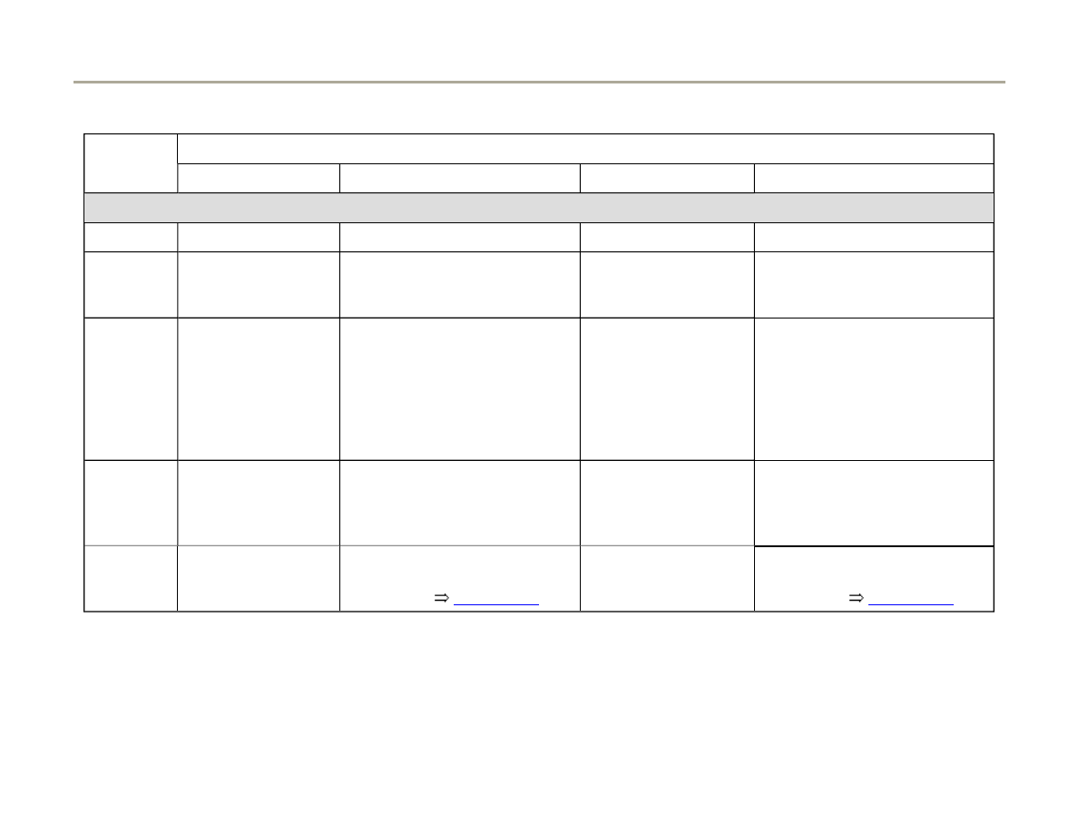
01-135
Display fields
1
2
3
4
Display group 036: Operational readiness of oxygen sensors behind TWC (Bank 1 and Bank 2)
Display
x.xxx Volt
Test ON
x.xxx Volt
Test ON
Indicated
Voltage of oxygen
sensor behind TWC,
Bank 1
Diagnostic condition
Voltage of oxygen
sensor behind TWC,
Bank 2
Diagnostic condition
Work
range
0.000V - 1.000 Volt
Test OFF
Test ON
B1-S2 OK
B1-S2 not OK
0.000V - 1.000Volt
Test OFF
Test ON
B2-S2 OK
B2-S2 not OK
Value
less than 0.4 Volt or
greater than 0.5
Volt
B1-S2 OK
less than 0.4 Volt or
greater than 0.5 Volt
B2-S2 OK
Note
IF "B1-S2 not OK" is
displayed: Check DTC
Memory
Page 01-14
.
If "B2-S2 not OK" is
displayed: Check DTC
memory
Page 01-14
.
If the specified value in display field 2 "B1-S2
OK" and in display field 4 "B2-S2 OK" is
reached:
- Press -C- button.
Page 169 of 183
Motronic system, On Board Diagnostic (OBD)
1/17/2006
http://127.0.0.1:8080/audi/servlet/Display?action=Goto&type=repair&id=AUDI.C5.FU03.01.1.110.11

01-136
Work step 10: Diagnosis of oxygen sensor
control system
Test requirements
Engine at idle
System in Basic Setting
Q
Input display group number XXX
Indicated on display
- Press buttons -0-, -3- and -7- to select "display group 037" and confirm
with -Q- button.
System in Basic Setting 37
1
2
3
4
Indicated on display
- Check specified value in display field 4.
Page 170 of 183
Motronic system, On Board Diagnostic (OBD)
1/17/2006
http://127.0.0.1:8080/audi/servlet/Display?action=Goto&type=repair&id=AUDI.C5.FU03.01.1.110.11

01-137
Display fields
1
2
3
4
Display group 037: Oxygen sensor control system (Bank 1)
Display
xx.x %
x.xxx Volt
xxx ms
Test ON
Indicated
Load
Voltage of oxygen
sensor behind TWC,
Bank 1
Correction value between
oxygen sensors 1 and 2, Bank
1
Diagnostic condition
Work range
0 - 175
%
0.000 - 1.000 Volt
---
Test OFF
Test ON
Syst. OK
Syst. not OK
Specified
value
13.5 -
25.0 %
0.000 - 1.000 Volt
-500ms to 800ms
Syst. OK
Note
If "Syst. not OK" is displayed:
Check DTC memory
Page 01-
14
.
If specified value of "Syst. OK" is reached:
- Press -C- button.
- Press buttons -0-, -3- and -8- to select "display
group 038" and confirm input with -Q- button.
Page 171 of 183
Motronic system, On Board Diagnostic (OBD)
1/17/2006
http://127.0.0.1:8080/audi/servlet/Display?action=Goto&type=repair&id=AUDI.C5.FU03.01.1.110.11
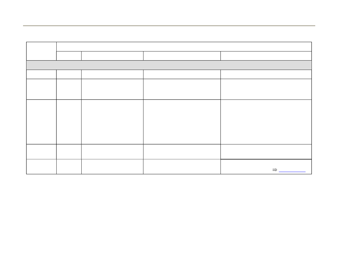
01-138
Display fields
1
2
3
4
Display group 038: Oxygen sensor control system (Bank 2)
Display
xx.x %
x.xxx Volt
xxx ms
Test ON
Indicated
Load
Voltage of oxygen sensor
behind TWC, Bank 2
Correction value between
oxygen sensors 1 and 2, Bank
2
Diagnostic condition
Work
range
0 - 175
%
0.000 - 1.000 Volt
---
Test OFF
Test ON
Syst. OK
Syst. not OK
Value
13.5 -
25.0 %
0.000 - 1.000 Volt
-500ms to 800ms
Syst. OK
Note
If "Syst. not OK" is displayed:
Check DTC memory
Page 01-14
.
If specified value of "Syst. OK" is reached:
- Press -C- button.
Page 172 of 183
Motronic system, On Board Diagnostic (OBD)
1/17/2006
http://127.0.0.1:8080/audi/servlet/Display?action=Goto&type=repair&id=AUDI.C5.FU03.01.1.110.11

01-139
Work step 11: Diagnosis of oxygen sensor
aging behind catalytic converter
Test requirements
Engine running at 1900 - 2200 RPM
System in Basic Setting
Q
Input display group number XXX
Indicated on display
- Press buttons -0-, -4- and -3- to select "display group 043" and confirm
input with -Q- button.
System in Basic Setting 43
1
2
3
4
Indicated on display
- Check specified value in display field 4.
Page 173 of 183
Motronic system, On Board Diagnostic (OBD)
1/17/2006
http://127.0.0.1:8080/audi/servlet/Display?action=Goto&type=repair&id=AUDI.C5.FU03.01.1.110.11
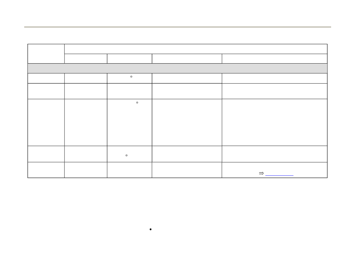
01-140
Display fields
1
2
3
4
Display group 043: Oxygen sensor aging oxygen sensor behind TWC (Bank 1)
Display
xxxx/RPM
xxx C
x.xxx V
Test ON
Indicated
Engine speed
(RPM)
Catalyst
temperature
Voltage of oxygen sensor
behind TWC Bank 1
Diagnostic condition
Work range
0 - 6800 RPM
70 - 850 C
0.000 - 1.000 Volt
Test OFF
Test ON
B1-S2 OK
B1-S2 not OK
Specified
value
1900 - 2200
RPM
greater than 320
C
0.000 - 1.000 Volt
B1-S2 OK
Note
If "B1-S2 not OK" is displayed: Check
DTC memory
Page 01-14
.
If specified value of "B1-S2 OK" is reached:
- Press -C- button.
Test requirements
Engine running at 1900 - 2200 RPM
Page 174 of 183
Motronic system, On Board Diagnostic (OBD)
1/17/2006
http://127.0.0.1:8080/audi/servlet/Display?action=Goto&type=repair&id=AUDI.C5.FU03.01.1.110.11

- Press buttons -0-, -4- and -4- to select "display
group 044" and confirm input with -Q- button.
Page 175 of 183
Motronic system, On Board Diagnostic (OBD)
1/17/2006
http://127.0.0.1:8080/audi/servlet/Display?action=Goto&type=repair&id=AUDI.C5.FU03.01.1.110.11
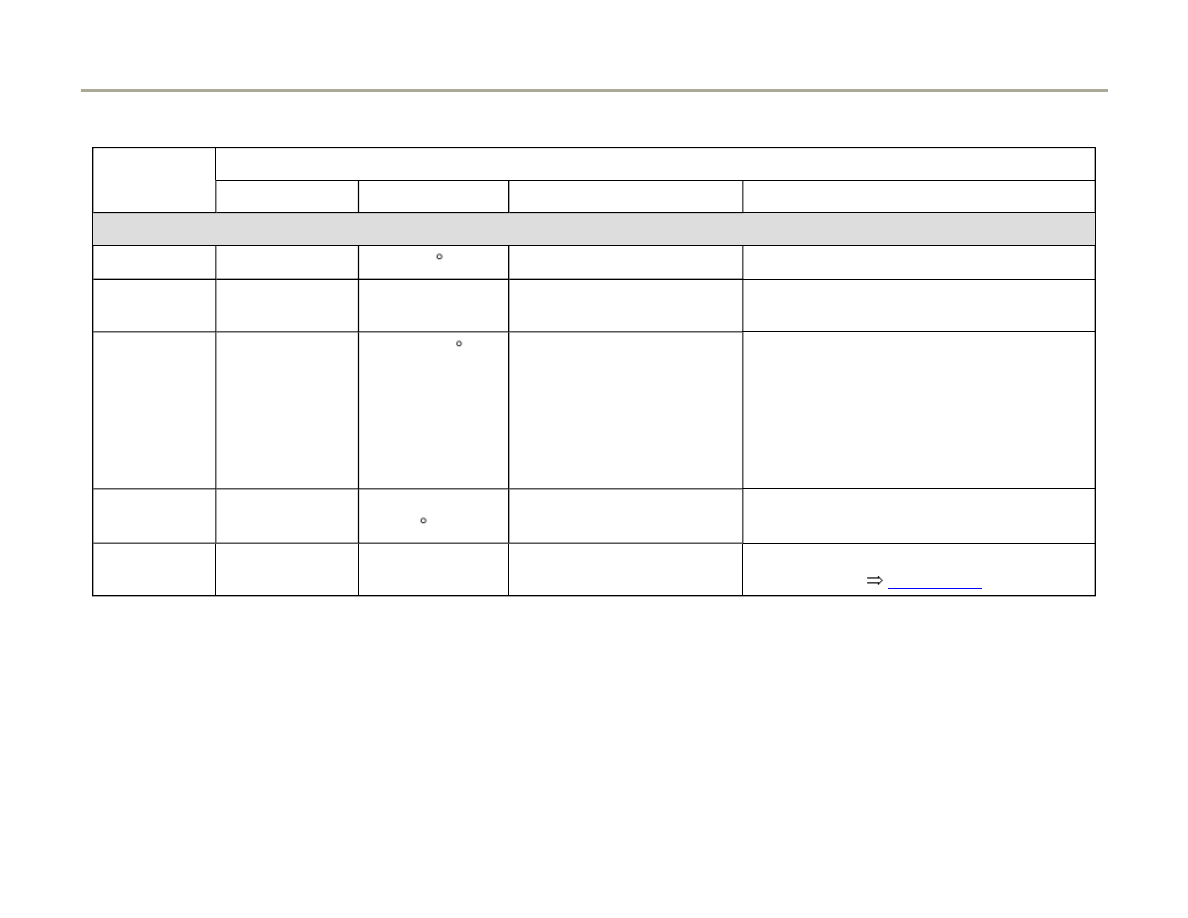
01-141
Display fields
1
2
3
4
Display group 044: Oxygen sensor aging oxygen sensor behind TWC (Bank 2)
Display
xxxx/RPM
xxx C
x.xxx Volt
Test ON
Indicated
Engine speed
(RPM)
Catalyst
temperature
Voltage of oxygen sensor
behind TWC Bank 2
Diagnostic condition
Work range
0 - 6800 RPM
70 - 850 C
0.000 - 1.000 Volt
Test OFF
Test ON
B2-S2 OK
B2-S2 not OK
Specified
value
1900 - 2200
RPM
greater than 320
C
0.000 - 1.000 Volt
B2-S2 OK
Note
If "B2-S2 not OK" is displayed: Check
DTC memory
Page 01-14
.
If specified value of "B2-S2 OK" is reached:
- Press -C- button.
Page 176 of 183
Motronic system, On Board Diagnostic (OBD)
1/17/2006
http://127.0.0.1:8080/audi/servlet/Display?action=Goto&type=repair&id=AUDI.C5.FU03.01.1.110.11

01-142
Work step 12: Diagnosis of catalytic
converter
Test requirements
Engine running at 1900 - 2200 RPM
System in Basic Setting
Q
Input display group number XXX
Indicated on display
- Press buttons -0-, -4- and -6- to select "display group 046" and confirm
input with -Q- button.
System in Basic Setting 46
1
2
3
4
Indicated on display
Note:
The test duration for catalytic converter diagnosis takes approximately 60
seconds.
- Check specified value in display field 4.
Page 177 of 183
Motronic system, On Board Diagnostic (OBD)
1/17/2006
http://127.0.0.1:8080/audi/servlet/Display?action=Goto&type=repair&id=AUDI.C5.FU03.01.1.110.11
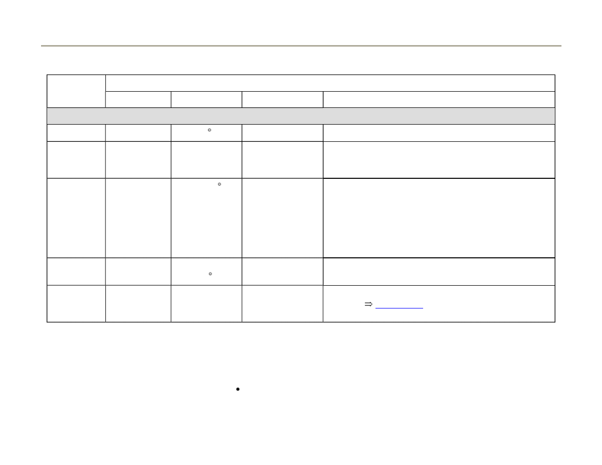
01-143
Display fields
1
2
3
4
Display group 046: Diagnostic of catalytic converter (Bank 1)
Display
xxxx/RPM
xxx C
x.x s
---
Indicated
Engine speed
(RPM)
Catalyst
temperature
Catalytic
converter
conversion
Diagnostic condition
Work
range
0 - 6800 RPM
70 - 850 C
0.0 - 0.99
Test OFF
Test ON
Cat B1 OK
Cat B1 not OK
Specified
value
1900 - 2200
RPM
greater than
350 C
0.0 - 0.80
Cat B1 OK
Note
If "Cat B1 not OK" is displayed: Check DTC
memory
Page 01-14
. If no malfunction is stored
replace catalytic converter.
If the specified value "Cat B1 OK" is reached:
- Press -C- button
Engine running at 1900 - 2200 RPM
Page 178 of 183
Motronic system, On Board Diagnostic (OBD)
1/17/2006
http://127.0.0.1:8080/audi/servlet/Display?action=Goto&type=repair&id=AUDI.C5.FU03.01.1.110.11

- Press buttons -0-, -4- and -7- to select "display
group 047" and confirm input with -Q- button.
Page 179 of 183
Motronic system, On Board Diagnostic (OBD)
1/17/2006
http://127.0.0.1:8080/audi/servlet/Display?action=Goto&type=repair&id=AUDI.C5.FU03.01.1.110.11
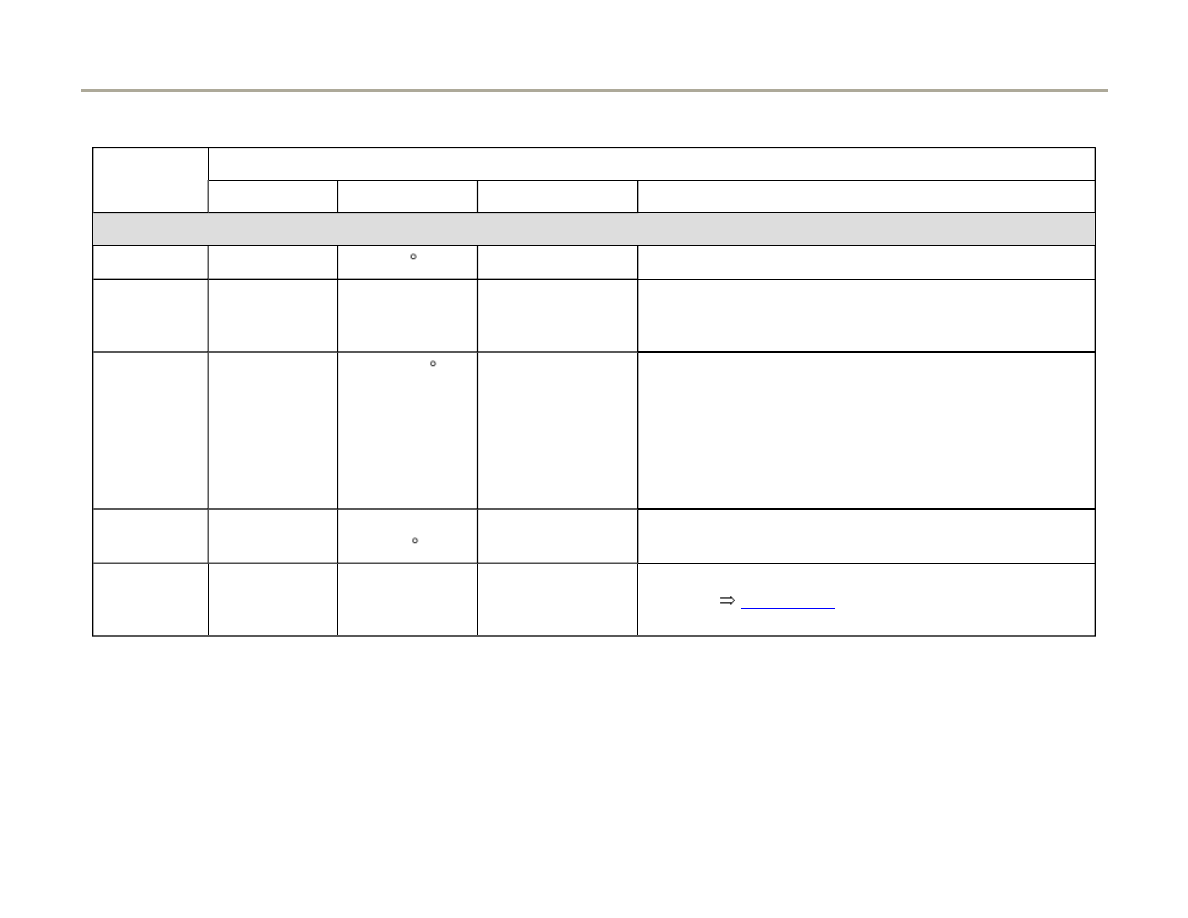
01-144
Display fields
1
2
3
4
Display group 047: Diagnostic of catalytic converter (Bank 2)
Display
xxxx/RPM
xxx C
x.x seconds
---
Indicated
Engine speed
(RPM)
Catalyst
temperature
Catalytic
converter
conversion
Diagnostic condition
Work
range
0 - 6800 RPM
70 - 850 C
0.0 - 0.99
Test OFF
Test ON
Cat B2 OK
Cat B2 not OK
Specified
value
1900 - 2200
RPM
greater than
350 C
0.0 - 0.80
Cat B2 OK
Note
If "Cat B2 not OK" is displayed: Check DTC
memory
Page 01-14
. If no malfunction is stored
replace catalytic converter.
If the specified value "Cat B2 OK" is reached:
- Press -C- button
Page 180 of 183
Motronic system, On Board Diagnostic (OBD)
1/17/2006
http://127.0.0.1:8080/audi/servlet/Display?action=Goto&type=repair&id=AUDI.C5.FU03.01.1.110.11

01-145
Work step 13: Diagnosis of Secondary Air
Injection (AIR) system (only on vehicles with
automatic transmission), on vehicles with
manual transmission continue with work step
14
Page 01-147
Note:
The secondary air pump runs for a few seconds
during the secondary air injection system
diagnosis.
Engine at idle sped
System in Basic Setting
Q
Input display group number XXX
Indicated on display
- Press buttons -0-, -7- and -7- to select "display group 077" and confirm
input with -Q- button.
System in Basic Setting 77
1
2
3
4
Indicated on display
Note:
The test duration for the secondary air injection system takes
approximately 60 seconds.
- Check specified value in display field 4.
Page 181 of 183
Motronic system, On Board Diagnostic (OBD)
1/17/2006
http://127.0.0.1:8080/audi/servlet/Display?action=Goto&type=repair&id=AUDI.C5.FU03.01.1.110.11
01-146
Display fields
1
2
3
4
Display group 077: Diagnostic of secondary air injection system (Bank 1)
Display
xxxx/RPM
xx.x g/s
xx %
Test ON
Indicated
Engine speed
(RPM)
Air
mass
Relative air mass secondary air
injection system
Diagnostic condition
Work
range
0 - 6800 RPM
Test OFF
Test ON
Syst. OK
Syst. not OK
Abort
Value
650 - 750 RPM
+10 % to -100 %
Syst. OK
Note
If "Syst. not OK": Check DTC memory
Page 01-14
.
If the specified value of "Syst. OK" is reached:
- Press -C- button.
- Press buttons -0-, -7- and -8- to select "display
group 078" and confirm input with -Q- button.
Page 182 of 183
Motronic system, On Board Diagnostic (OBD)
1/17/2006
http://127.0.0.1:8080/audi/servlet/Display?action=Goto&type=repair&id=AUDI.C5.FU03.01.1.110.11
01-147
Display fields
1
2
3
4
Display group 078: Diagnostic of secondary air injection system (Bank 2)
Display
xxxx/RPM
xx.x g/s
xx %
Test ON
Indicated
Engine speed
(RPM)
Air
mass
Relative air mass secondary air
injection system
Diagnostic condition
Work
range
0 - 6800 RPM
Test OFF
Test ON
Syst. OK
Syst. not OK
Abort
Value
650 - 750 RPM
+10 % to -100 %
Syst. OK
Note
If "Syst. not OK": Check DTC memory
Page 01-14
.
If the specified value of "Syst. OK" is reached:
- Press button.
Work step 14: Readiness code, displaying
- Display readiness code again (measure of
control)
Page 01-112
.
Page 183 of 183
Motronic system, On Board Diagnostic (OBD)
1/17/2006
http://127.0.0.1:8080/audi/servlet/Display?action=Goto&type=repair&id=AUDI.C5.FU03.01.1.110.11
Wyszukiwarka
Podobne podstrony:
BentleyPublishers com Audi A6 C5 Service Reset
BentleyPublishers com Audi A6 C5 4 2L Secondary Air Injection Maintenance
BentleyPublishers com Audi A6 C5 Sunroof drain cleaning
BentleyPublishers com Audi A6 C5 4 2L Secondary Air Injection Maintenance
AllRoadFAQ com Audi C5 2 7T 402 AirLoweringMod[1]
AllRoadFAQ com Audi C5 2 7T PressureLeakTesting
AllRoadFAQ com Audi C5 2 7T 402 AirLoweringMod[1]
Bentley com Audi TB 01 03 07
Fourtitude com Audi A6 C5 Brake Information PartNumbers
AudiForums com Audi A6 C5 IceLink iPod Install
AudiWorld com Audi A6 C5 Boor Blade Installation DIY
Audizine com Audi A6 C5 2 8 30V Throttle Body Cleaning DIY
Audi BarryStuff com Audi RS6 C5 Sirius XM Satellite Radio DIY Install
kodowanie sterownikow Audi A4, auta, Diagnostyka dokumety, procedury diagnostyczne
więcej podobnych podstron