A
B
C
A34-0163
1
1
1
13-A043
Technical Bulletin
Important!
Please give copies to
all your Audi Technicians
C 01–03–07
E 2003 Audi of America, Inc.
All rights reserved. Information contained in this document is based on the latest information available at the time of printing and is subject to the copyright and other intellectual property rights of
Audi of America, Inc., its affiliated companies and its licensors. All rights are reserved to make changes at any time without notice. No part of this document may be reproduced, stored in a retrieval system, or transmitted in any form or by any means, electronic,
mechanical, photocopying, recording, or otherwise, nor may these materials be modified or reposted to other sites, without the prior expressed written permission of the publisher.
1 of 4
Subject:
Model(s):
Group:
Number:
Date:
Diagnostic Trouble Code (DTC) P1127, P1129, or P1557
Stored in DTC Memory
2000
ä 2003
01
03–07
May 6, 2003
S4, A6,
allroad with 2.7L
(Eng. code APB, BEL)
Supersedes T.B. Repair Group 01 number 00–04 dated Aug. 18, 2000
Condition
DTC P1127 and/or P1129 and/or P1557stored
in DTC memory.
Can also be accompanied by poor throttle
response or engine shake at steady speeds.
May be caused by loss of pressure from the
turbocharger due to cracks or tears in the
intake air duct “Y” boot under the fastening
clamp.
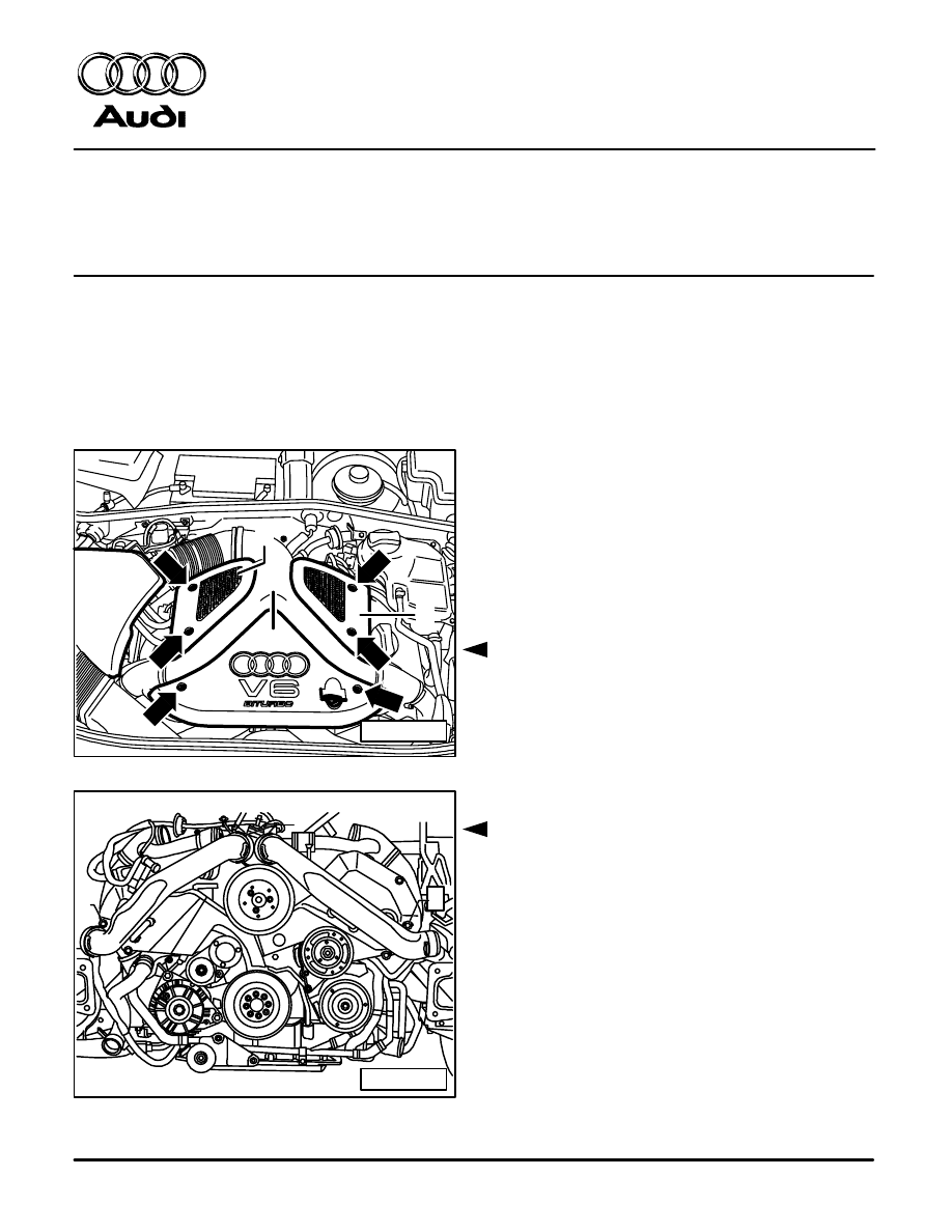
Service
– Remove upper engine cover -C- only (see
Repair Manual Group 15
Cylinder head
covers removing and installing).
– Remove bolts -1- for pressure hoses.
z Allows hose to move when removing “Y”
hose from Throttle Valve Control Module
-J338-.
24-A117
1
2
3
24-A114
Technical Bulletin
Important!
Please give copies to
all your Audi Technicians
C 01–03–07
E 2003 Audi of America, Inc.
All rights reserved. Information contained in this document is based on the latest information available at the time of printing and is subject to the copyright and other intellectual property rights of
Audi of America, Inc., its affiliated companies and its licensors. All rights are reserved to make changes at any time without notice. No part of this document may be reproduced, stored in a retrieval system, or transmitted in any form or by any means, electronic,
mechanical, photocopying, recording, or otherwise, nor may these materials be modified or reposted to other sites, without the prior expressed written permission of the publisher.
2 of 4
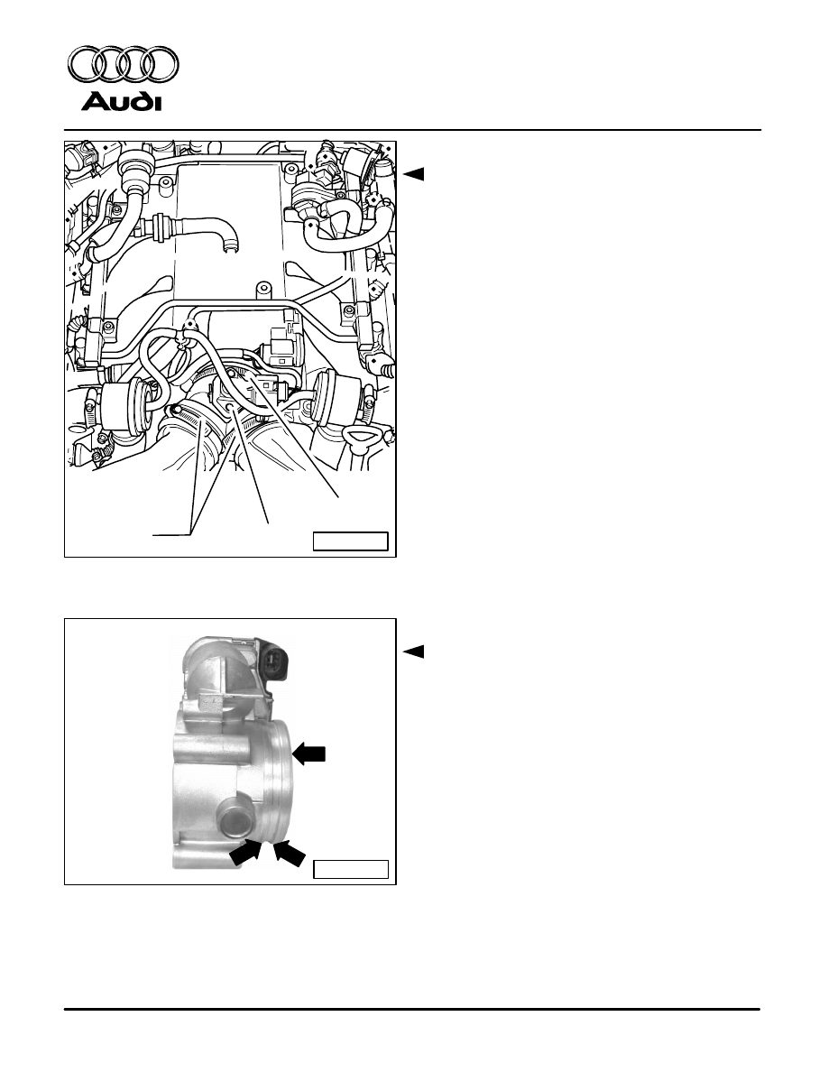
– Remove Charge Air Pressure Sensor (G31)
item -2-.
Note:
Make note of clamp orientation and position.
– Loosen clamps -1- to pressure hoses.
– Loosen clamp -3- at Throttle Valve Control
Module -J338-.
– Remove Intake air duct (“Y” hose) from
Throttle Valve Control Module -J338- and
inspect.
If intake air duct is cracked or torn it must be
replaced.
A tear may have been caused by sharp edges
on Throttle Valve Control Module -J338- con-
necting flange cutting into the rubber duct (ar-
row) which connects to pressure hoses.
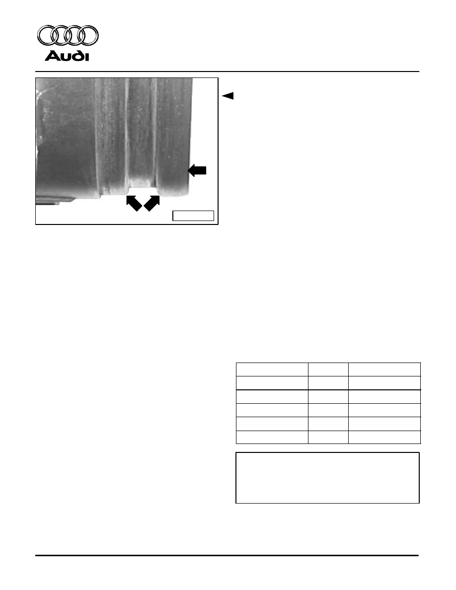
Prior to installing new duct:
– Remove four Throttle Valve Control Module
-J338- fasteners.
– Remove Control Module.
– Using a round file, round over sharp outer
edges of the inner groove and outer edge of
control module -arrows- (around the entire
periphery of control module) to a maximum
radius of 0.5 mm (approx. 0.02 in.).
24-A116
Technical Bulletin
Important!
Please give copies to
all your Audi Technicians
C 01–03–07
E 2003 Audi of America, Inc.
All rights reserved. Information contained in this document is based on the latest information available at the time of printing and is subject to the copyright and other intellectual property rights of
Audi of America, Inc., its affiliated companies and its licensors. All rights are reserved to make changes at any time without notice. No part of this document may be reproduced, stored in a retrieval system, or transmitted in any form or by any means, electronic,
mechanical, photocopying, recording, or otherwise, nor may these materials be modified or reposted to other sites, without the prior expressed written permission of the publisher.
3 of 4
– Using 120 grit emery cloth, finish outer edges
of the inner groove and outer edge of control
module -arrows- (around the entire
periphery of control module).
– After rework is finished, clean shavings and
any accumulated dirt/oil film from outer and
inner surfaces of control module using air
pressure and solvent (brake cleaner works
well).
– For heavier deposits of dirt / oil film, apply
Wynn’s
X–Tend
V.I.C. Combustion
Chamber Cleaner: Part No: 61510 (U.S.),
Part No: 61512 (CAN.) on a soft clean cloth
then, clean interior surfaces using this cloth
(one can of cleaner will do many vehicles,
therefore it is considered shop supply).
– Clean the interior surfaces of throttle valve
control module -J338- housing with a soft
clean cloth.
– Reinstall Throttle Valve Control Module
-J338- using a new gasket (see table).
z Fastener torque = 10Nm. 1Nm.
– Install new parts as follows.
Description
Quantity
Part No:
Intake Air Duct
1
078 133 356 T
Clamp
1
078 133 343
Clamp
2
078 133 343 A
Clamp
1
N 904 119 01
Gasket
1
078 133 073J
CAUTION!
Part numbers are for reference only.
Always check with your Parts Dept. for
the latest parts information.
z Clamp torque = 1 0.3 Nm.

Technical Bulletin
Important!
Please give copies to
all your Audi Technicians
C 01–03–07
E 2003 Audi of America, Inc.
All rights reserved. Information contained in this document is based on the latest information available at the time of printing and is subject to the copyright and other intellectual property rights of
Audi of America, Inc., its affiliated companies and its licensors. All rights are reserved to make changes at any time without notice. No part of this document may be reproduced, stored in a retrieval system, or transmitted in any form or by any means, electronic,
mechanical, photocopying, recording, or otherwise, nor may these materials be modified or reposted to other sites, without the prior expressed written permission of the publisher.
4 of 4
Note:
Use extreme care to properly install the intake
air duct to the Throttle Valve Control Module
-J338- using new clamps in the original
positions on the intake air duct.
– Reinstall upper engine cover.
– Clear any stored DTC’s.
– Set readiness code.
When procedure applies to vehicles with-
in the New Vehicle Limited Warranty, use
the following:
Part Identifier:
2434
Labor Operation:
Replace Boot
24343150
80TU
Wyszukiwarka
Podobne podstrony:
Audi TB 01 03 05 Readiness Quick Reference
Audi TB 01 03 05 Readiness Quick Reference
Audi TB 01 03 05 Readiness Quick Reference
BentleyPublishers com Audi C5 OBD Diagnostics
BentleyPublishers com Audi A6 C5 Service Reset
BentleyPublishers com Audi A6 C5 4 2L Secondary Air Injection Maintenance
BentleyPublishers com Audi A6 C5 Sunroof drain cleaning
TI 01 03 07 01 T pl
BentleyPublishers com Audi A6 C5 4 2L Secondary Air Injection Maintenance
Kryon 07 01 03 Publiczny Przekaz
Wprowadzenie do filozofii nr.01 - 03.10.07, Nauka, Psychologia
audi tb 91 04 03
Przyklady wyklad 01 2013 Excel2010 BOND 2014 03 07
Przyklady wyklad 01 2013 Excel2003 BOND 2014 03 07
syst tr 1 (2)TM 01 03)13
CHF dr gębalska 17 01 03
więcej podobnych podstron