
Combustion Gas Turbine
Fuel Pumps
Colfax White Paper
The modern combustion gas turbine is one of the most reliable
machines in use and a workhorse of the electric power generation
industry. It can be on-site and running in a relatively short
period, providing quick additional power capability when needed.
The fuel system is a key component of a combustion gas turbine
power plant or system (Figure 1).
The most common fuels for these machines are natural gas and
distillate fuel oil. Many industrial machines are delivered suitable
to burn either gaseous or liquid fuel. Thus, a liquid-fuel system
is frequently a part of the installation. Even if natural gas is the
primary fuel, liquid fuel as a backup is very common, to provide
for interruptions in gas supplies. Some excess fuel products from
refineries are relatively inexpensive. Naphtha is currently a very
popular gas turbine fuel in India, due to government regulation.
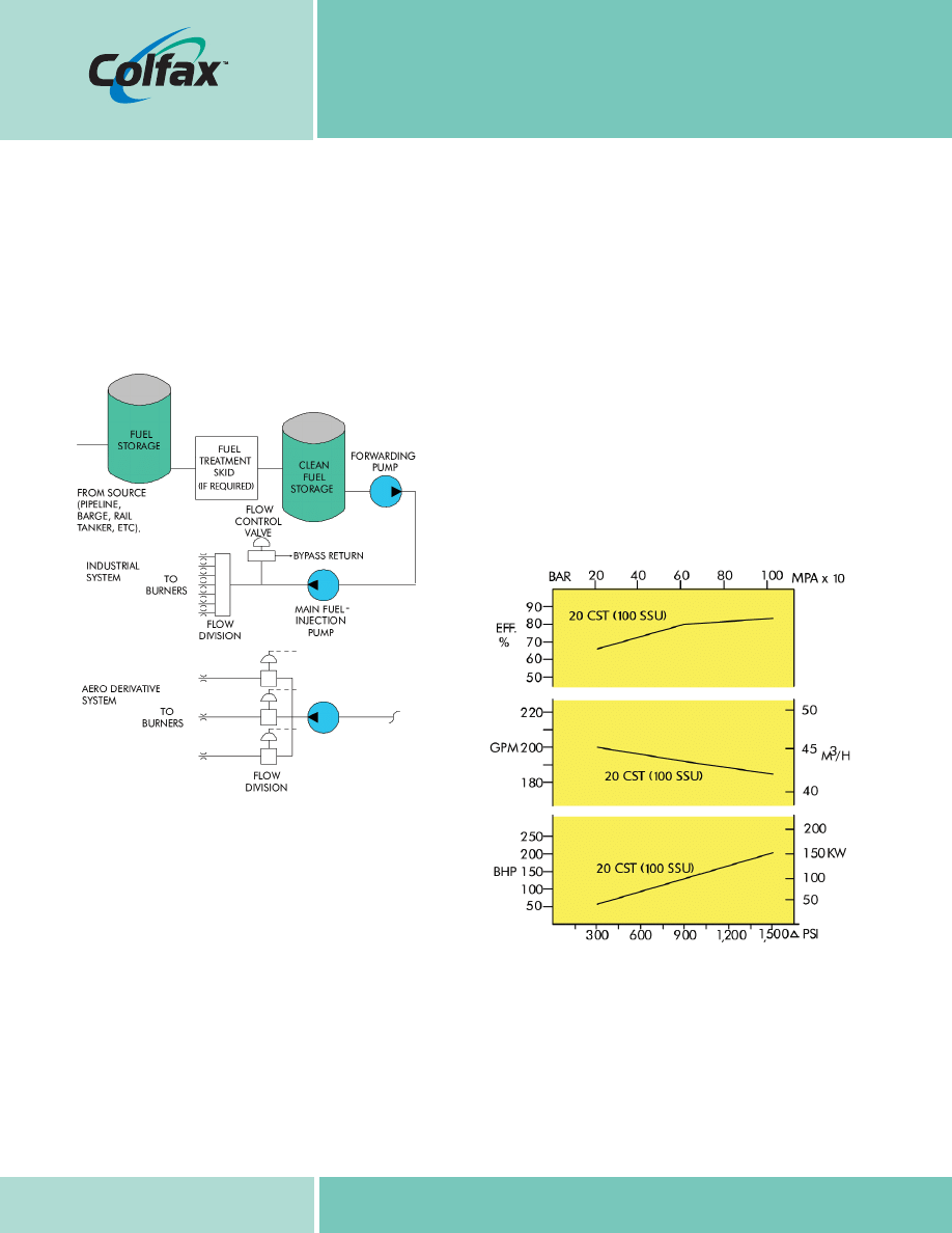
Typical rotary positive displacement main fuel pump performance
is illustrated in Figure 2. As can be seen, pump efficiency is quite
good. Flow performance is also fairly flat over a wide pressure range.
FUELS
Common liquid fuels for combustion gas turbines include:
- Naphtha natural gas liquids
- Methanol various jet fuels
- Kerosene natural gasoline
- Crude oil distillate (no. 2 Fuel)
- Gas oil residual (bunker) fuel oil
Many of these fuels require special treatment and/or handling,
both to be safe to use and to minimize excessive erosion or corrosion
to the hot-gas parts of the machine. For example, naphtha is an
extremely volatile liquid, and some purchasers of pumps for
this fuel specify a barrier system for the pump shaft seals.
Colfax White Paper
Figure 2
Liquid fuel system schematic
Figure 1
Liquid Fuel System Schematic
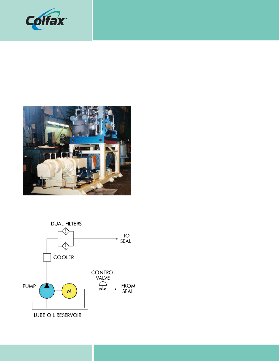
Figure 3 shows a twin-screw naphtha fuel injection pump that
includes a lube oil barrier system, to ensure that any shaft-seal leakage
is comprised of lube oil into the fuel. Such leakage can be readily
detected, so that an orderly shutdown can be initiated to investigate
a possible seal leak. Figure 4 is a simplified schematic of the barrier
system. The instrumentation is not shown for clarity.
FUEL TREATMENT
Some crude oils and virtually all residual-fuel oils will require heating,
both to reduce viscosity for efficient handling and to ensure that a
maximum viscosity, usually less than 20 centistokes (100 SSU), for
the burner nozzles is achieved. Low-pressure fuel-treatment skids
provide the necessary fuel conditioning components, in a package
ready for site installation. A normal residual oil may require heating in
the range of 225 to 250°F (107 to 121°C) or higher. These fuels
will typically require pretreatment to remove solid contaminants
and may have additives introduced that provide some corrosion-
inhibiting performance when the fuel is burned. A water wash to
remove objectionable salts may be needed; this process involves
dissolving water-soluble salts in water and then removing the water,
normally by centrifuge. In addition, gas turbines using crude or
residual fuels are normally started and shut down while burning a
light, clean fuel, usually distillate fuel oil. This leaves the injection
fuel system – including the pump, flow-division mechanism and
nozzles – clean for the next restart; Otherwise, crude oils or
residual-fuel oils may solidify and/or leave deposits that will inhibit a
successful restart.
When the main fuel is a heated fuel and the startup/shutdown
fuel is unheated, consideration should be given to the thermal
shock that will be imposed on the main fuel injection pump and
downstream fuel system components, when the pump’s suction
flow is switched from an ambient temperature fuel to one of
elevated temperature. These pumps and other fuel system components
typically have very close internal clearances, and drastic or sudden
temperature swings should be minimized.
BLACK START
Gas turbines are frequently supplied in “black-start” configurations
– that is, equipped to be started and brought on-line with no
external source of power. Among other issues in such a configuration
is that of supplying fuel oil at sufficient flow and pressure to initiate
turbine combustion mode. This is normally accomplished by having
the fuel injection pump driven from an accessory gear (attached
pump) that, in turn, is driven by the gas turbine. The gas turbine
is rotated using a diesel engine, itself a black-start configuration.
The attached main fuel pump is sized to deliver the minimum
light-off flow at maximum light-off pressure at minimum light-off
speed. Once combustion begins the turbine is self-sustaining and
Colfax White Paper
Figure 3
Twin-screw Naphtha Main Gas Turbine Fuel Pump
Figure 4
Simplified Fuel Pump Seal Barrier System
is brought to normal running speed with the diesels being clutched
out of the accessory gear and stopped. At normal turbine speed, the
fuel pump will deliver slightly in excess of the maximum required
flow rate, due to being sized for the low-speed light-off condition.
FUEL RECIRCULATION
Note that it is common practice that the main fuel injection pump
control valve and bypass relief-valve flow be returned to the inlet
side of the pump. When burn rates are low and bypass pressures
are low (no or low load running), there are usually no problems,
as the power input to the pump is also low. When the pump’s
power draw is high, (substantial to full load on the turbine), any
bypassed flow is converted to temperature rise within the
bypassed fuel. Continuous high-flow bypass to the pump inlet can
overheat the fuel, resulting in pump damage. This condition can
exist especially if something such as a failed downstream-flow
divider causes the main pump relief valve to bypass back to the
main pump inlet. The preferred bypass return location is upstream
of the fuel-treatment/ forwarding pumps or back to the fuel storage
tanks if the distance is not excessive. In either of these preferred
return locations, a larger volume of fuel can dissipate the heat
gain before the temperature rise becomes excessive. If the fuel is
continuously heated as part of its preparatory treatment, the optimum
return location is upstream of the heaters; this will reduce the heater
load and improve operating efficiency. If recirculation is directed to
the main fuel pump inlet, then pump-liquid suction temperature
should be instrumented for alarm or shutdown, if an excessive
temperature is reached.
MAIN FUEL PUMPS
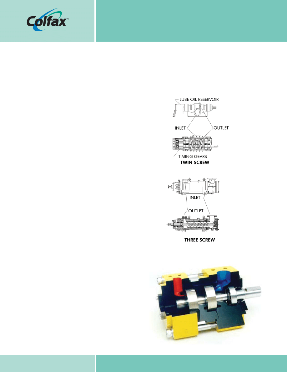
Most power generation gas turbines use industrial-grade, heavy-
duty main fuel pumps, typically twin-screw or three-screw designs
(see Figure 5). Such pumps are not flight qualified, having far too
low a power-to-weight ratio. Aero-derivative gas turbines will
sometimes use their equivalent flight-qualified main fuel pumps,
which are most ordinarily of the gear pump design. Multistage,
industrial gear pumps (Figure 6) are now also available for use
on these machines. Both the gear-type and three-screw-type
pumps use two-pole electric-motor direct-drive speeds of 2,900
revolutions per minute (rpm) (50 hertz [Hz]) or 3,500 rpm (60
Hz), or four-pole speeds of 1,450 rpm (50 Hz) or 1,750 rpm (60
Hz). The largest sizes, as well as the twin-screw pumps, use
four-pole electric-motor speeds. Specific pump configurations
depend to varying degrees on the fuel type, operating temperature,
fuel viscosity range, required pressure rise and flow rate. Main fuel
pumps have been supplied for pressures just above 2,000 pounds
per square inch (psi).
Colfax White Paper
Figure 5
Screw Pump Designs for Gas Turbine Fuel Injection
Figure 6
Multistage Gear-Type High-Pressure Fuel-Injection Pump

FLOW SIZING
Required pump flow rate depends on a number of variables,
including turbine power rating, site conditions, turbine thermal
efficiency and the heating value of the liquid fuel to be used. The
net heating value for distillate fuel is in the order of 128,000
British thermal units (Btu) per gallon. At this heating value, a 100
percent thermally efficient combustion gas turbine will, therefore,
need 0.445 gallons per minute (gpm) (1.68 liters per minute
[l/m]) per megawatt (MW) exclusive of control flow allowances.
With a thermal efficiency of 30 percent and a control flow
allowance of +15 percent, a 100MW machine will need a pump
rated to deliver about 170 gpm (645l/m). At a fuel-pressure rise
across the pump of 1,200 psi (83 bar), a typical requirement, the
fuel pump will require a 150-horsepower (HP) (112-kilowatt [kW])
driver and could be expected to operate at around 80 percent
efficiency. For standardized fuel system designs, pumps would be
sized to provide the required fuel flow for the maximum possible
turbine power rating, while pumping the lowest net heating-value
fuel for which the system is suitable.
Trends in numbers of main fuel pumps continue to evolve. The
most reliable systems will have two 100 percent capacity main fuel
pumps, one acting as a standby for the other. This arrangement
can be found in power plants whose primary or only fuel is liquid
and in which full-load continuous operation is the norm. The use
of three 50 percent capacity pumps will provide backup pump
availability, as well as the ability to run partial flow, for partial-load
applications. For situations in which liquid fuel is a backup fuel
only and/or interrupted service is not catastrophic, a single 100
percent capacity fuel pump is the most common arrangement.
Black-start systems having the main fuel pump driven from the
accessory gear can also have a 100 percent backup motor driven
standby pump, if desirable.
Nearly all installations include fuel-unloading pumps, to deliver
fuel to storage tanks. Additionally there are usually fuel-forwarding
pumps that deliver fuel to the main injection pumps or the fuel-
treatment skid, if such treatment is necessary. The fuel-treatment
skids frequently have forwarding pumps, as well. Most of these
ancillary pumps are for low-pressure operation and of the
centrifugal or screw-type designs, depending on the economics
and specifiers’ preferences. For heavier, higher-viscosity fuels,
such as bunker fuel or crude oil, these pumps are almost always
twin- or three-screw designs. Pumps can often be paired for main
standby service, to ensure uninterrupted operation.
Colfax White Paper
Imo is a registered trademark and Colfax is a trademark of Colfax Corporation. All other trademarks are the property of their respective owners.
©2008 Colfax Corporation. All rights reserved.
Colfax Corporation
8730 Stony Point Parkway
Suite 150
Richmond, VA 23235 USA
T: 804.327.5689
F: 804.560.4076
www.colfaxcorp.com
Colfax Europe,
Middle East, Africa
Allweilerstr. 1
78301 Radolfzell
Germany
+49.(7732).86-0
+49.(7732).86-436
Colfax Asia Pacific
Suite 1708
Universal Mansion
168 Yuyuan Road
200040 Shanghai, China
021.62481395
021.63737422
021.63868183
Colfax Americas
1710 Airport Road
Monroe, NC 28110 USA
T: 704.289.6511
F: 704.289.9273
Wyszukiwarka
Podobne podstrony:
Comparative Climate White Paper V4
eProcurement White Paper Final
EC09 Initiatives Proposal White Paper doc
FORTE Immersed Boundary White Paper
JM White Paper R6A
White Paper
Four Essential Facts White Paper
uk modaf erm implementation white paper v1 2008
FORTE G Equation White Paper
BFD Technology White Paper
white paper c11 453495
Security and Azure SQL Database White paper
Art & Intentions (final seminar paper) Lo
May 2002 History HL Paper 3 EU
First 2015 Writing sample paper Nieznany
No Longer White
więcej podobnych podstron