
Predicting Emissions in Direct
Injection Gasoline Engines
with Immersed Boundary CFD
Simulations
March 19, 2014
REACTION DESIGN
+1 858-550-1920

Reaction Design 1
Abstract
Designing internal combustion engines for lower emissions while maintaining high performance is one of
the top challenges of today’s engine manufacturers: Regulatory agencies require cleaner burning engines
even as the market demands more efficient, powerful motor vehicles with improved fuel economy. To
streamline the design of high-efficiency, low-emissions engines, computational fluid dynamics (CFD)
simulations allow engine designers to visualize and test fuel and ignition behaviors within a combustion
chamber, using software instead of costly physical prototyping. Virtual prototyping with CFD provides
engine manufacturers a fast way to design cleaner, more efficient engines by accurately simulating ignition
and fuel dynamics.
However, accurately modeling these behaviors in a combustion chamber is a complex task, particularly
with direct injection technologies. Ensuring that the simulations are accurate enough to predict real engine
performance or emissions is a challenge. Meeting that challenge requires exacting modeling technologies
to capture precise fuel vaporization and burning behaviors, ignition dynamics, and combustion kinetics, all
of which must translate reliably to real-world results.
Tracking Soot Production
Soot is a major contributor to airborne pollutants, and soot production is a major consideration for today’s
advanced engine designers. Soot formation involves complex chemical interactions with multiple precursor
elements, combined with the physical interactions that take place in an engine. Once a soot particle is
formed, it can grow and combine with other soot particles through agglomeration, or it can oxidize.
Accurately modeling soot formation within the combustion chamber is very challenging with conventional
CFD simulations, particularly for modern direct injection engines. In a conventional gasoline engine, fuel
injectors spray fuel into the intake manifold, where the fuel vaporizes and mixes with air. The fuel-air vapor
is then drawn into the combustion chamber where it ignites via spark ignition. In gasoline direct injection
(GDI) engines, liquid fuel is injected directly into the combustion chamber where (similar to Diesel engines)
the fuel is vaporized and rapidly mixed with the in-cylinder air prior to ignition.
Direct injection engines are generally more fuel efficient and can produce lower emissions than port-
injected gasoline engines. However, under certain conditions, soot formation can build up in the
combustion chamber and lead to significant particulate emissions.
In direct-injection engines, the fuel is sprayed into the chamber at high speed, with some droplets striking
the combustion chamber wall or valve surfaces. These spray/wall interactions—the outcomes of collisions
between airborne spray particles and the wall surfaces—can take several forms, including wall-film
formation and fuel splashing. These differing spray/wall interactions impact the vaporization of the fuel
within the chamber, which in turn impacts how completely the fuel burns during combustion. Residual
unburned fuel not only lowers engine efficiency, it can also lead to soot-producing conditions.
Reaction Design 2
Accurately modeling spray/wall interactions is critical for predictive engine modeling especially for
reduction of soot formation. However, modeling spray dynamics within a direct injection engine is
computationally very complex. Employing a body-fitted grid as a computational framework allows direct
use of the physical boundary in the cell calculations. However, mesh generation for such meshes is time-
consuming and expertise-intensive, and it also typically requires severe distortion of computational cells to
fit the mesh along the curvilinear physical boundaries. These highly deformed surface cells can introduce
inaccuracy and convergence issues into the numerical solution. Cut-cell meshes, on the other hand, may be
generated easily, but the cutting of the cells along the physical boundaries can also introduce numerical
issues due to the distorted shapes or very small cell sizes required to resolve complex shapes.
The Immersed Boundary Method
Automated mesh generation based on the immersed boundary method with ray tracing to track droplet
locations, as used by the FORTÉ CFD Package from Reaction Design, can accurately model the location and
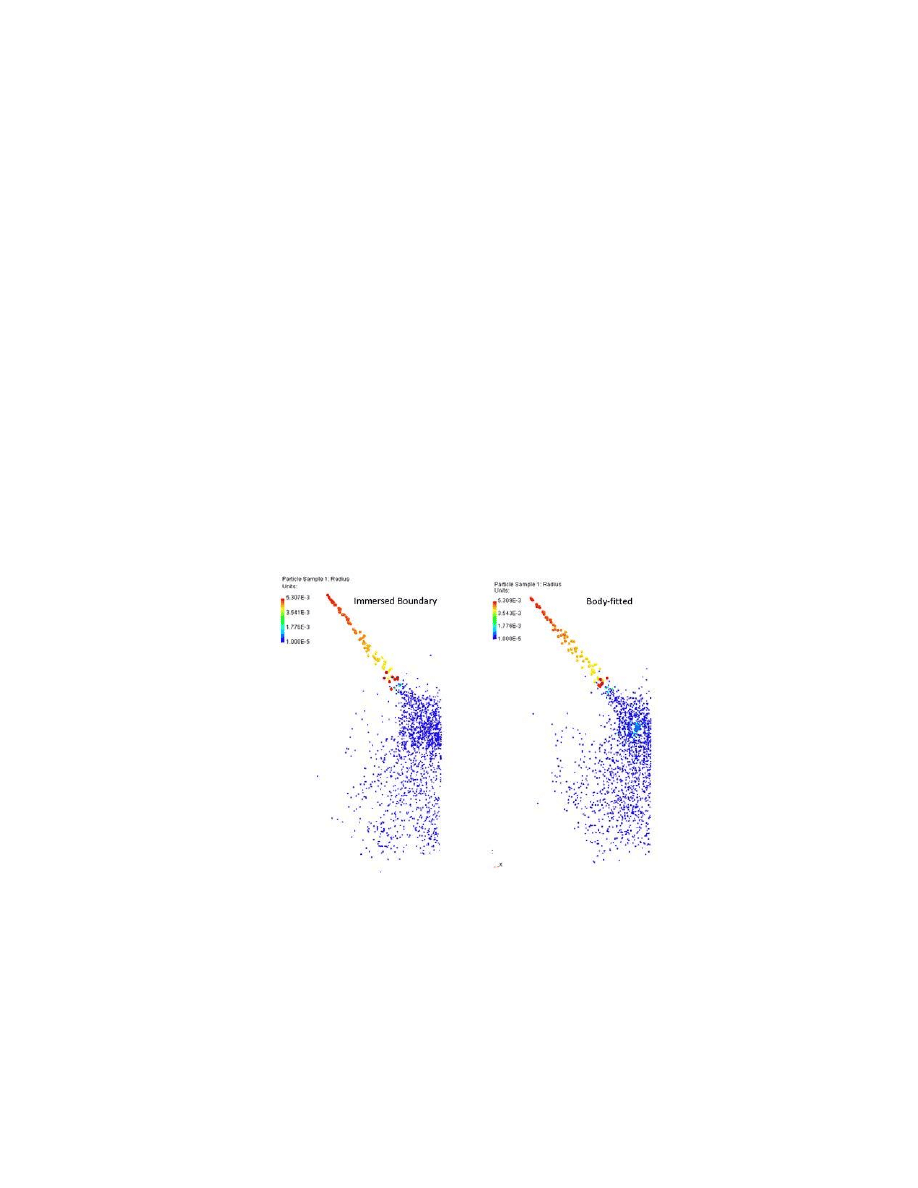
movement of spray particles along the wall of a computational domain (see Figure 1). The mesh is based on
an underlying Cartesian grid, in which all cells are perfect cubes. The grid is intersected by the physical
boundary and the location of the boundary’s surface mesh is maintained throughout the simulation for use
in tracking spray-wall interactions as well as in formulating boundary conditions that enforce known
conditions on the physical boundaries. This is accomplished without deforming or cutting the
computational cells.
Figure 1: The immersed-boundary particle tracking method is effective and accurate compared
to the body-fitted method
Soot formation process.
1
With the immersed boundary approach, ray-tracing is used to track and locate the locations of particles (or
groups of fuel droplets). During each computational time step, the particle travels along a straight line at a
known velocity. When that path intersects a surface, FORTÉ determines where it will be in the vicinity of
the surface or where it will end up on the surface. For any given initial location and direction vector, the
ray-tracing method can accurately locate the “piercing” location on the surface mesh. Further ray-tracing

Reaction Design 3
calculations then determine the particle’s rebounding direction from the wall (if the particle remains an
airborne particle after bouncing back) or the moving direction along the wall (if the particle merges into the
film). These motions contribute to film stripping phenomena, which can be predicted with FORTÉ.
Through use of the immersed boundary method and ray-tracing algorithms, FORTÉ directly uses the
physical boundary of the computation domain, ensuring that both the airborne spray and wall film particles
are confined within the actual system boundary.
Summary
Using these computational methods, FORTÉ can accurately model the behavior of fuel spray and wall
impingement at the boundary of the combustion chamber or any other surface in the simulation, where
the spray/wall dynamics take place. This provides engineers with accurate simulations to guide the design
of engines that increase the efficiency of fuel combustion and minimize the formation of soot.
FORTÉ provides robust and fast engine simulations, built on well-established computational techniques
rather than compute-heavy approaches that rely on extreme mesh refinements. FORTÉ helps ensure that
engine designers have accurate simulations of critical spray/wall interactions that contribute to unburned
hydrocarbon emissions and the formation of pollutants, helping lead to the creation of cleaner, higher
performance engines.
References
1. Liang, L., Shelburn, A., Wang, C., Hodgson, D., Meeks, E., “Implementation and Validation of
Spray/Wall Interaction Models in Immersed Boundary CFD,” International Multidimensional Engine
Modeling User's Group Meeting,
April 15, 2013, Detroit, Michigan, pp 5.
Wyszukiwarka
Podobne podstrony:
FORTE G Equation White Paper
6770 Fuel White Paper 1
Comparative Climate White Paper V4
eProcurement White Paper Final
EC09 Initiatives Proposal White Paper doc
JM White Paper R6A
White Paper
Four Essential Facts White Paper
uk modaf erm implementation white paper v1 2008
BFD Technology White Paper
white paper c11 453495
Security and Azure SQL Database White paper
Art & Intentions (final seminar paper) Lo
May 2002 History HL Paper 3 EU
First 2015 Writing sample paper Nieznany
No Longer White
Nov 2003 History Europe HL paper 3
więcej podobnych podstron