
BFD Technology White Paper
Hangzhou H3C Technologies Co., Ltd.
1
/
14
BFD Technology White Paper
Keyword: BFD
Abstract: BFD provides a standard and fast failure detection mechanism. This document
discusses the implementation and typical applications of BFD.
Acronyms:
Acronym
Full spelling
BFD
Bidirectional Forwarding Detection
UDP
User Datagram Protocol

BFD Technology White Paper
Hangzhou H3C Technologies Co., Ltd.
2
/
14
Table of Contents
1 Overview........................................................................................................................................ 3
4 References .................................................................................................................................. 14

BFD Technology White Paper
Hangzhou H3C Technologies Co., Ltd.
3
/
14
1 Overview
1.1 Background
To protect key applications, a network is usually designed with redundant backup
links. Devices need to quickly detect communication failures and restore
communication through backup links as soon as possible. On some links, such as
POS links, devices detect link failures by sending hardware detection signals.
However, some other links, such as Ethernet links, provide no hardware detection
mechanism. In that case, devices can use the hello mechanism of a protocol for
failure detection, which has a failure detection rate of more than one second. Such a
rate is too slow for some applications. Some routing protocols, such as OSPF and IS-
IS, provide a fast hello mechanism for failure detection, but this mechanism has a
failure detection rate of at least one second and is protocol-dependent.
1.2 Benefits
BFD provides a general-purpose, standard, medium- and protocol-independent fast
failure detection mechanism. It has the following benefits:
z
Detecting failures on any bidirectional forwarding paths, such as direct physical
link, virtual link, tunnel, MPLS LSP, multi-hop path, and unidirectional link,
between network devices.
z
Providing consistent fast fault detection time for upper-layer applications.
z
Providing a failure detection time of less than one second for faster network
convergence, short application interruptions, and enhanced network reliability.
2 BFD Implementation
2.1 Mechanism
BFD establishes a session between two network devices to detect failures on the
bidirectional forwarding paths between the devices and provide services for upper-
layer protocols. BFD provides no neighbor discovery mechanism. Protocols that BFD
services notify BFD of devices to which it needs to establish sessions. After a session
BFD Technology White Paper
Hangzhou H3C Technologies Co., Ltd.
4
/
14
is established, if no BFD control packet is received from the peer within the
negotiated BFD interval, BFD notifies a failure to the protocol, which then takes
appropriate measures. The following section describes the operation of BFD for
OSPF.
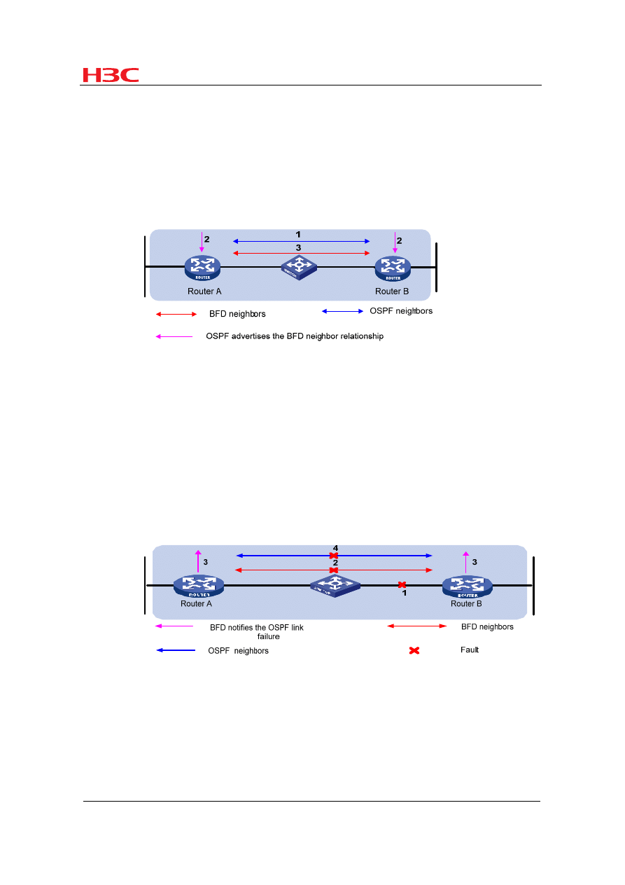
1. BFD session establishment
Figure 1
BFD session establishment
1) OSPF discovers neighbors by sending Hello packets and establish neighbor
relationships.
2) After establishing neighbor relationships, OSPF notifies BFD of the neighbor
information, including destination and source addresses.
3)
BFD uses the information to establish BFD sessions.
2. BFD fault detection
Figure 2
BFD fault detection
1)
A link failure occurs.
2)
Upon detection of the link failure, BFD clears the session.
3)
BFD notifies the neighbor unreachability to OSPF.
4)
OSPF terminates the neighbor relationship on the link.
BFD Technology White Paper
Hangzhou H3C Technologies Co., Ltd.
5
/
14
There are two BFD operating modes: asynchronous and demand. At present, the
Comware platform supports only the asynchronous mode. A device operating in the
asynchronous mode periodically sends BFD control packets. It tears down the BFD
session if it receives no BFD control packet from the peer within the BFD interval.
The Comware platform also supports Echo-mode BFD. A device operating in the
echo mode periodically sends BFD echo packets. The peer device returns the
received BFD echo packets back without processing them. If the sending device
receives no BFD echo packet from the peer within the BFD interval, the session is
considered down.
Both ends of a BFD session may be directly (one hop away from each other) or
indirectly connected. BFD echo packets can only detect failures for directly connected
neighbors. That is, BFD echo packets are sent over a single hop. BFD control
packets, however, can detect failures for directly and indirectly connected neighbors.
That is, BFD control packets can be sent over one or multiple hops.
2.2 BFD Packets
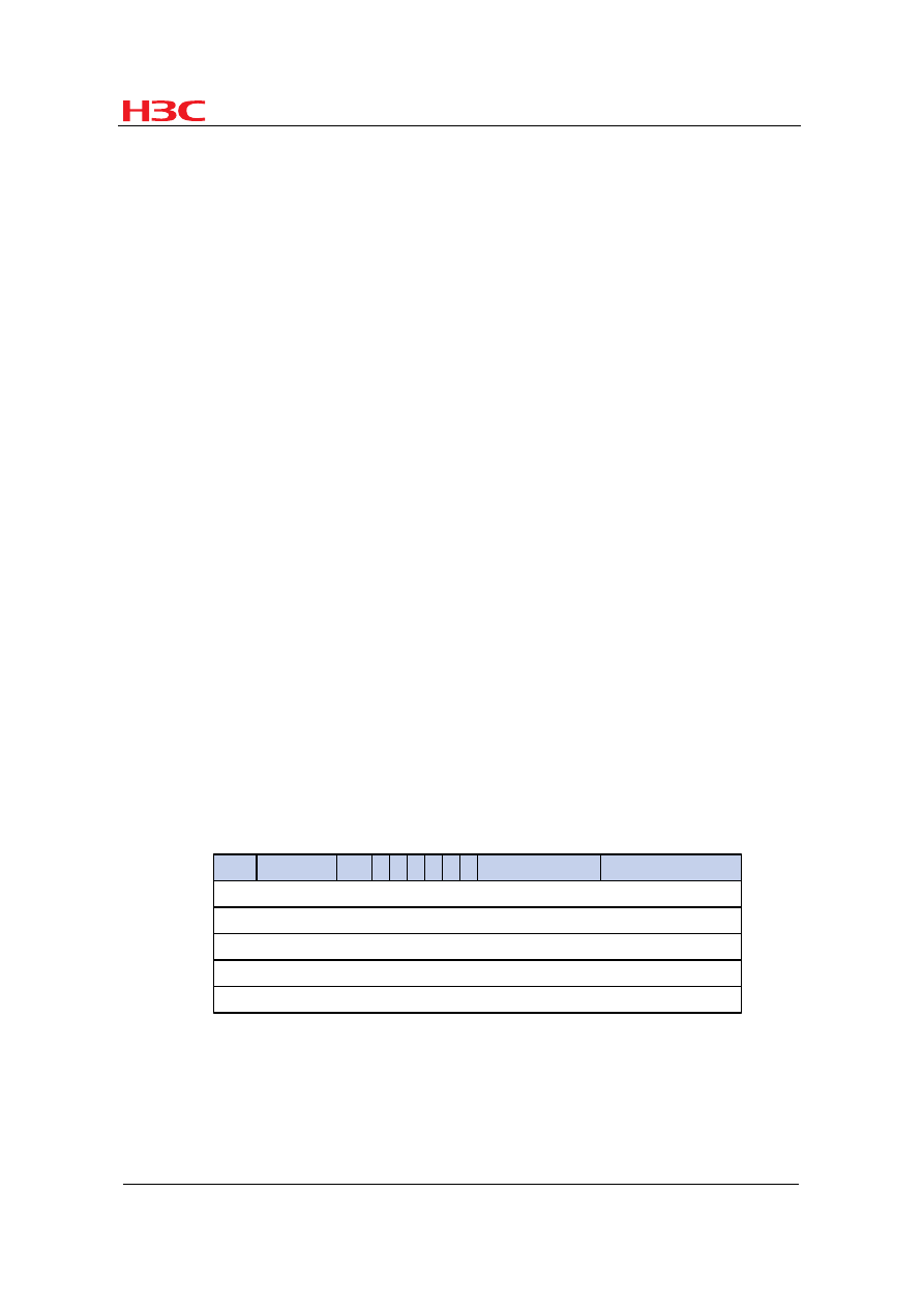
2.2.1 BFD Control Packets
A BFD control packet consists of the required fields and the optional authentication
fields.
2.2.1 Figure 3 shows the format of the required fields:
Vers
Diag
Sta
P F C A D
Detect Mult
Length
My Discriminator
Your Discriminator
Desired Min TX Interval
Resired Min RX Interval
Required Min Echo RX Interval
0
7
R
23
31
Figure 3
BFD control packet format
Figure 4 shows the format of the optional authentication fields.

BFD Technology White Paper
Hangzhou H3C Technologies Co., Ltd.
6
/
14
Figure 4
BFD control packet (authentication fields)
Table 1 Description of the fields of a BFD control packet
Field
Description
Vers
BFD version. The current version is 1.
Diag
This bit indicates the reason for the last transition of the local protocol
from up to some other state.
Sta
Current BFD session state. Its value can be 0 for AdminDown, 1 for
Down, 2 for Init, and 3 for Up.
P
If it is set to 1, the transmitting system requests the connection
acknowledgement or acknowledges a parameter change.
F
If it is set to 1, the transmitting system responds to a received BFD
control packet that has the Poll (P) bit set.
C
If set to 1, it means the BFD implementation for the transmitting system
is independent of its control plane.
A
If it is set to 1, the control packet contains the authentication field and
the session is authenticated.
D
If set to 1, it means the transmitting system wishes to operate in the
demand mode; if set to 0, it means the transmitting system ignores the
demand mode or cannot operate in the demand mode.
R
Reserved. It is set to 0 during transmission and ignored during
reception.
Detect Mult
Detect time multiplier.
Length
BFD control packet length, in bytes.
My Discriminator
A unique, nonzero discriminator value generated by the transmitting
system, used to demultiplex multiple BFD sessions between the same
pair of systems.
Your Discriminator
This field reflects back the received value of My Discriminator or is 0 if
that value is unknown.
Desired Min TX
Interval
Minimum interval at which the local protocol wishes to send BFD
control packets, in milliseconds.
Required Min RX
Interval
Minimum interval at which the local system can receive BFD control
packets, in milliseconds.
Required Min
Echo RX Interval
This is the minimum interval, in microseconds, between received BFD
Echo packets that this system is capable of supporting. If this value is
zero, the transmitting system does not support the receipt of BFD Echo
packets.
Auth Type
Authentication type used by BFD control packets.
Auth Len
Authentication field length, including authentication type field and
authentication length field, in bytes.

BFD Technology White Paper
Hangzhou H3C Technologies Co., Ltd.
7
/
14
BFD control packets are encapsulated in UDP packets, using destination port 3784
and a source port from 49152 to 65535.
2.2.2 BFD Echo Packets
BFD echo packets provide a fault detection mechanism without the use of BFD
control packets. One end sends BFD echo packets to the peer, which returns
received BFD echo packets back without processing them. Therefore, no BFD echo
packet format is defined, as long as the transmitting end can distinguish between
sessions through packet contents.
BFD echo packets are encapsulated in UDP packets, using destination port 3785,
with the IP address of the transmitting interface as the destination IP address and a
configured source IP address, which must not cause ICMP redirection.
2.3 BFD Session Establishment
Note:
The following section describes the process of session establishment and fault
detection by sending BFD control packets.
Before a BFD session is established, there are two BFD operation modes: active or
passive:
z
Active mode: Before a session is established, BFD actively sends BFD control
packets regardless of whether any BFD control packet is received from the peer.
z
Passive mode: Before a session is established, no BFD control packet is sent
until a BFD control packet is received from the peer.
During session initialization, at least one end of the two in communication must
operate in the active mode for a session to be established. The following example
shows the session establishment process with both ends working in the active mode.
The session establishment process with one end in active mode and the other in
passive mode is the same.
BFD Technology White Paper
Hangzhou H3C Technologies Co., Ltd.
8
/
14
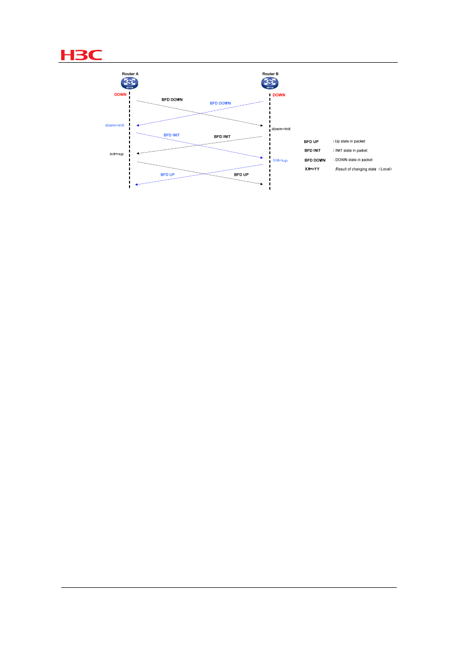
Figure 5
BFD session establishment
BFD uses a three-way handshake mechanism to establish sessions. The transmitting
end fills the Sta field with its current session state in a transmitted BFD control packet.
The receiving end changes its session state based on the Sta field value in the
received BFD control packet and its own session status to establish a session.
1) As shown in the above figure, upon receipt of a notification from an upper-layer
application, Routers A and B send a BFD control packet in DOWN state to the
peer.
2) When Router B receives the BFD control packet in DOWN state, the local
session state transits from DOWN to INIT. In the BFD control packet sent
subsequently, the Sta field is filled with a value of 2, indicating the session state
is INIT. Router A experiences the same BFD state transition as Router B.
3) When Router A receives the BFD control packet in INIT state from the peer, the
local session state transits from INIT to UP. In the BFD control packet sent
subsequently, the Sta field is filled with a value of 3, indicating the session state
is UP. Router B experiences the same BFD state transition as Router A.
4)
Both BFD peers are UP. A session is established successfully and BFD starts to
detect link failures.
2.4 Timer Negotiation
Before a BFD session is established, BFD control packets are sent every one second
to reduce traffic. After a session is established, BFD control packets are sent at the
negotiated interval for fast detection, and the BFD control packet transmit interval and
detection timer are negotiated. If a BFD session is valid, these timers can be
BFD Technology White Paper
Hangzhou H3C Technologies Co., Ltd.
9
/
14
negotiated and modified without affecting session state. The timers for different BFD
session directions are negotiated independent of each other and therefore can be
different.
The BFD control packet transmit interval is the greater of the Desired Min TX Interval
of the local end and the Required Min RX Interval of the peer.
The detection timer is the Detect Mult of the BFD control packets transmitted by the
peer times the negotiated BFD control packet transmit interval of the peer.
If the Desired Min TX Interval of the local end increases, the actual BFD control
packet transmit interval of the local end cannot be changed until the local end
receives a packet with the F bit set from the peer. This ensures that the peer has
increased the detection timer before the BFD control packet transmit interval
increases on the local end, thus avoiding detection timer timeout errors on the peer.
If the Required Min RX Interval of the local end decreases, the detection timer of the
local end cannot be changed until the local end receives a packet with the F bit set
from the peer. This ensures that the peer has decreased the BFD control packet
transmit interval before the local end decreases the detection timer, thus avoiding
detection timer timeout errors on the local end.
If the Desired Min TX Interval decreases, so does the BFD control packet transmit
interval on the local end immediately. If the Required Min RX Interval increases, so
does the detection timer on the local end immediately.
The following describes the timer negotiation process after a parameter change.
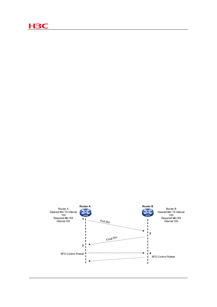
Figure 6
BFD detection timer negotiation

BFD Technology White Paper
Hangzhou H3C Technologies Co., Ltd.
10
/
14
A BFD session is established between Router A and Router B. Both routers have the
same Desired Min TX Interval (hereinafter referred to as TX) and Required Min RX
Interval (hereinafter referred to as RX) of 100 milliseconds and the same Detect Mult
of 3. According to timer negotiation rules, the BFD control packet transmit interval is
Router A's TX or Router B's RX, whichever is greater, namely, 100 milliseconds,
Router B's transmit interval is also 100 milliseconds, and both routers have a
detection timer of 300 milliseconds.
If TX and RX of Router A increase to 150 milliseconds:
1) Router A compares its RX (150 milliseconds) with Router B's TX (100
milliseconds) and thus changes the detection timer of the local end to 450
milliseconds. Meanwhile, Router A sends a BFD control packet (with a TX and
RX of 150 milliseconds) whose P bit is set to the peer.
2) Upon receipt of the packet, Router B replies to Router A with a BFD control
packet whose F bit is set (with a TX and RX of 100 milliseconds). Meanwhile,
Router B compares the RX in the received packet with the TX of the local end.
As TX is greater, Router B's transmit interval is changed to 150 milliseconds.
After comparing the RX of the local end with the TX of the peer, Router B also
changes its detection timer to 450 milliseconds.
3) Router A receives a BFD control packet with the F bit set from the peer. After
comparing the RX in the received packet and the TX of the local end, Router A
calculates the new transmit interval as 150 milliseconds.
4) The timer negotiation is complete. The BFD control packet transmit interval and
detection timer for the routers are 150 milliseconds and 450 milliseconds
respectively.
2.5 Fault Detection
After BFD session establishment and timer negotiation, both ends start to transmit
BFD control packets at the negotiated interval. Each time a BFD control packet is
received, the detection timer is reset so that the session remains up. If no BFD
control packet is received within the detection timer, the BFD session state transits to
DOWN and BFD notifies the failure to the upper-layer application it services. The
upper-layer application then takes proper measures. When the BFD session on the
local end is DOWN, the Sta field of the BFD control packet transmitted to the peer is
BFD Technology White Paper
Hangzhou H3C Technologies Co., Ltd.
11
/
14
filled with a value of 1 to notify the peer that the session is DOWN. Then, the BFD
session state of the peer also transits to DOWN.
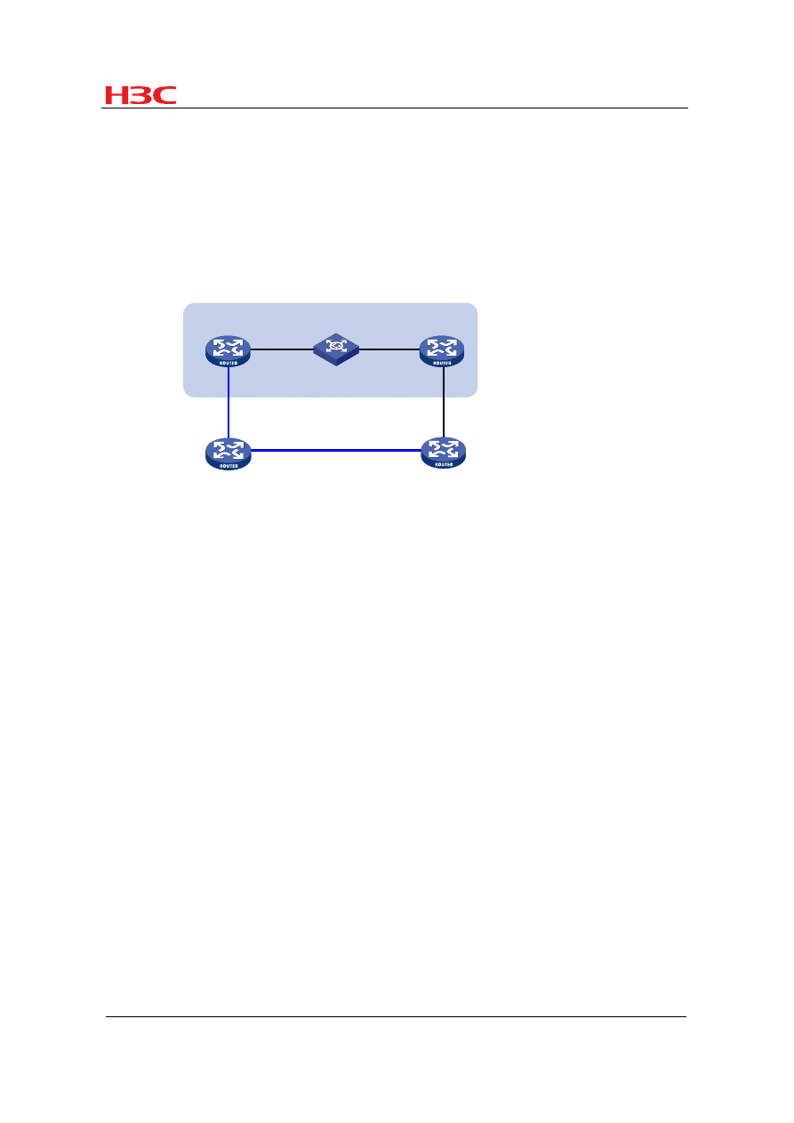
3 Application Scenarios
3.1 Configuring BFD for Routing Protocols
Router A
Router C
Router B
Router D
BFD
L2 Switch
Figure 7
Application scenario where BFD works with routing protocols
Router A and Router B are interconnected through a Layer-2 switch. Both routers run
a routing protocol.
As Router A and Router B are interconnected through a Layer-2 switch, a link failure
between the routers may not cause an interface to be DOWN, and the link failure can
be detected only through protocol handshake. After BFD is configured between
Router A and Router B, a link failure between the routers can be detected quickly.
Upon receipt of the link failure notification from BFD, the routing protocol recalculates
routes for fast convergence.
BFD Technology White Paper
Hangzhou H3C Technologies Co., Ltd.
12
/
14
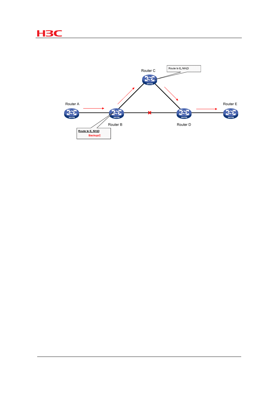
3.2 Configuring BFD for Fast Reroute
Figure 8
Application scenario where BFD is configured for fast reroute
Many delay-sensitive services on the Internet, such as audio and video services,
require fast route convergence. Configuring BFD for routing protocols or using the
fast route convergence technologies can greatly speeds up convergence but cannot
fully meet the failover requirements of audio and video services.
Configuring BFD for fast reroute can satisfy such requirements. Backup paths are
calculated in advance and master path failures are detected quickly. When the
master path fails, the traffic is directly switched to a backup path at the forwarding
plane rather than the control plane, thus greatly shortening service interruptions.
BFD Technology White Paper
Hangzhou H3C Technologies Co., Ltd.
13
/
14
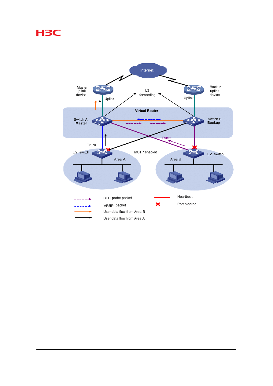
3.3 Configuring BFD for VRRP
Figure 9
Application scenario where BFD is configured for VRRP
With the Virtual Router Redundancy Protocol (VRRP) enabled, when the master
device fails, the backup device can quickly take over the forwarding task from the
master, thus minimizing user data flow interruptions. When the master fails, if the
backup receives no packet from the master within the preemption delay timer, the
backup becomes the new master, with a switchover time of over one second. After
BFD is configured for the backup to monitor the master, failures of the master can be
detected more quickly to shorten user data flow interruptions.
VRRP also monitors the status of the master's uplink. When the master works
normally but its uplink fails, user packets cannot be forwarded normally. VRRP
determines whether an uplink is normal by monitoring the uplink interface status.

BFD Technology White Paper
Hangzhou H3C Technologies Co., Ltd.
14
/
14
When the monitored interface is down, the master lowers its priority to initiate a
switchover. However, this mechanism depends on the protocol status; if the uplink
fails but the protocol status of the interface remains up, the failure cannot be detected
through VRRP. Configuring BFD for the VRRP master to monitor its uplink can solve
this problem.
4 References
z
Katz D., Ward D., "Bidirectional Forwarding Detection”, draft-ietf-bfd-base-05.
z
Katz D., Ward D., "Generic Application of BFD”, draft-ietf-bfd-generic-02.
z
Katz D., Ward D., "BFD for IPv4 and IPv6 (Single Hop)”, draft-ietf-bfd-v4v6-
1hop-05.
z
Katz D., Ward D., "BFD for Multihop Paths”, draft-ietf-bfd-multihop-03.
Copyright © 2008
Hangzhou H3C Technologies Co., Ltd. All rights reserved.
No part of this document may be reproduced or transmitted in any form or by any means without prior written consent of H3C
Technologies Co., Ltd.
This document is subject to change without notice.
Document Outline
Wyszukiwarka
Podobne podstrony:
6770 Fuel White Paper 1
Comparative Climate White Paper V4
eProcurement White Paper Final
EC09 Initiatives Proposal White Paper doc
FORTE Immersed Boundary White Paper
JM White Paper R6A
White Paper
Four Essential Facts White Paper
uk modaf erm implementation white paper v1 2008
FORTE G Equation White Paper
white paper c11 453495
Security and Azure SQL Database White paper
PORÓWNYWANIE TECHNOLOGII
19 Mikroinżynieria przestrzenna procesy technologiczne,
Technologia informacji i komunikacji w nowoczesnej szkole
Technologia spawania stali wysokostopowych 97 2003
SII 17 Technologie mobilne
więcej podobnych podstron