2002 CAMRY (EWD461U)
74
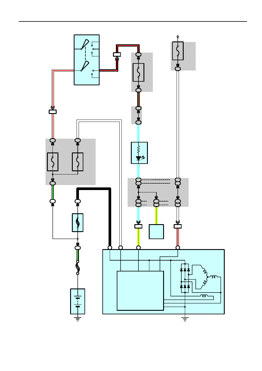
Charging
7
6
AM2
AM1
ACC
IG1
ST1
IG2
ST2
1L
4
1E
2
5A
ALT–S
30A
AM2
1A
2
120A ALT
(1MZ–FE)
100A ALT
(2AZ–FE)
1
1
B–
G
B–
G
W
W–
R
B–R
2
1
Battery
S
L
IG
B
IC Regulator
B
3
B
1
B
2
A
1
1
IF6
3
IL2
13
3B
3B
116
106
3B
3B
126
116
3B
3B
106
96
2G
8
2O
5
1C
7
10A
IG2
1C
8
IF1
8
14
IL2
3A
3A
107
117
(* 1)
(* 2)
3A
3A
67
57
10A
GAUGE1
From Power Source System (See Page 62)
2M
1
(* 1)
(* 2)
B
W–
R
B–
O
W
SB
W
SB
SB
Y–
G
W
Y–
G
R–
L
W
B
ALTL
Generator
G 1(A), G 2(B)
Body ECU
B 7
FL MAIN
3. 0W
Ignition SW
I15
B–R
Combination
Meter
C 7
18
* 1 : Automatic A/C
* 2 : Manual A/C
C
har
ge
27
29
2002 CAMRY (EWD461U)
75
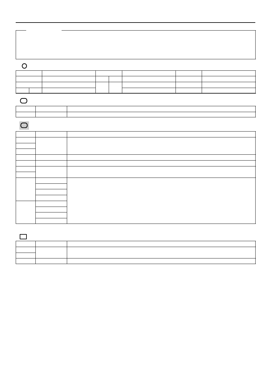
G2 (B) Generator
(B) 3–Ground : 13.9–15.1 volts with the engine running at 2000 rpm and 25
°
C (77
°
F)
13.5–14.3 volts with the engine running at 5000 rpm and 115
°
C (239
°
F)
(B) 1–Ground : 0–4 volts with the ignition SW at ON position and the engine not running
: Parts Location
Code
See Page
Code
See Page
Code
See Page
B7
G1
A
I15
C7
G2
B
G1
A
G2
B
: Relay Blocks
Code
See Page
Relay Blocks (Relay Block Location)
1
Engine Room R/B (Engine Compartment Left)
: Junction Block and Wire Harness Connector
Code
See Page
Junction Block and Wire Harness (Connector Location)
1A
1C
Engine Room Main Wire and Engine Room J/B (Engine Compartment Left)
1E
g
g
(
g
)
1L
Engine Wire and Engine Room J/B (Engine Compartment Left)
2G
Engine Room Main Wire and Driver Side J/B (Lower Finish Panel)
2M
Instrument Panel Wire and Driver Side J/B (Lower Finish Panel)
2O
Instrument Panel Wire and Driver Side J/B (Lower Finish Panel)
3A
3A
Instrument Panel Wire and Passenger Side J/B (Instrument Panel Brace RH)
Instrument Panel Wire and Passenger Side J/B (Instrument Panel Brace RH)
3B
3B
∗
1 : TMC Made Automatic A/C
∗
2 : TMC Made Manual A/C
∗
3 : TMMK Made Automatic A/C
∗
4 : TMMK Made Manual A/C
: Connector Joining Wire Harness and Wire Harness
Code
See Page
Joining Wire Harness and Wire Harness (Connector Location)
IF1
Engine Room Main Wire and Instrument Panel Wire (Right Side of Steering Column Tube)
IF6
Engine Room Main Wire and Instrument Panel Wire (Right Side of Steering Column Tube)
IL2
Engine Wire and Instrument Panel Wire (Behind the Glove Box)
Service Hints
Wyszukiwarka
Podobne podstrony:
Charging
WIRELESS CHARGING OF MOBILE PHONES USING MICROWAVES
Free Energy Bedini Device And Method For Pulse Charging A Battery Patent Info 2004
19 Starting Charging
batt charging time
14 Charging System Alternator
NX650 P Section 16 Battery charging
CHARGING
19 Starting and Charging
NiCd Charging Circuit
Charging
96ZJ 8C CHARGING SYSTEM
Honoré de Balzac Le Peau de chargin résumé
14 Charging System Alternator
NX650 P Section 16 Battery charging
LVCCFSB2005 113 GSM Intermittent Charging Indication
BMW E38 schematic Charging circuit
więcej podobnych podstron