1
AVR109: Self-programming
Features
•
AVR109 Code Fits in All AVR
®
Microcontrollers with Boot Block
•
Read and Write Both Flash and
EEPROM Memories
•
Uses the AVRProg Protocol
•
Read and Write Lock Bits
Introduction
This application note describes how an
AVR with the SPM instruction can be
configured for self-programming. The
AVR communicates via the UART with
a PC running AVRprog programming
software. This enables FLASH and
EEPROM programming without the need
for an external programmer.
A Boot Load program is placed inside
the Boot Section of the Flash memory.
This program handles communication
with the host PC, and facilitates pro-
gramming of both Flash and EEPROM.
Once programmed, different levels of
protection can be used to protect the
memories. The AVR offers a unique
flexibility, setting different levels of pro-
tection on the Boot and Application
areas of the Flash memory. Individual
protection levels can be selected for both
portions of memory.
SPM Explained
SPM can be used to erase a page in pro-
g r a m m e m o r y , t o w r i t e a p a g e i n
program memory that has already been
erased, filling the temporary page buffer
and to set Boot Loader lock bits. In other
devices, an entire page is programmed
simultaneously after first filling the tem-
porary page buffer. In all cases, the
program memory must be erased one
page at a time. When erasing the pro-
gram memory, the Z register is used as
page address. When writing the program
memory, the Z register is used as page
or word address, and the r1:r0 register
pair contains the data. When setting the
Boot Loader lock bits, the r1:r0 register
pa ir con tain s th e da ta . For a mo re
in-depth description on how this is done,
please refer to the device datasheet,
where a detailed description of SPM
usage is presented. The SPM instruction
can access the entire Flash, but can only
be executed from the boot section.
Memory Organization
The memory is divided into pages of 64
words each. An 8-Kbit device has 64
pages, a 16-Kbit device will have 128
pages, and so on.
Figure 1. Memory Sections
AVR microcontrollers with the self-
programming feature have their memory
organized in two main sections; the
Program Memory
Application Flash Section
Boot Flash Section
8-bit
RISC
Microcontroller
Application
Note
Rev. 1644A–03/00
AVR109
2
Application Flash section and the Boot Loader Flash sec-
tion. The size of these two sections is device dependent
and for most devices, scalable. In this case, the Boot
Loader size can be changed through the BOOTSZ fuses.
This feature allows for utilizing the memory where it is
needed. Applications requiring a simple Boot Loader can
allocate more Flash to the Application section.
Security Issues
Writing to the Flash memory is only allowed in a limited
SPM enable time window. To prevent accidental writing to
the Flash memory, all write operations must be executed
with the SPMEN I/O bit set. This bit enables the SPM
instruction for the next four cycles. If set together with
either BLBSET, PGWRT or PGERS, the following SPM
instruction will result in setting Boot Lock bits, doing a Page
Write or Page Erase, respectively. If only SPMEN is set,
the following SPM instruction will store the value in r1:r0 in
the temporary page buffer addressed by the Z pointer.
The Boot Lock Bits allow the user:
• To protect the entire Flash from a software update by the
MCU
• To protect the Boot Loader Flash section from a software
update by the MCU while the application section is
modified
• To only protect application Flash section from a software
update by the MCU
• To allow software update in the entire Flash
• To prevent LPM instructions executed in Application
Section to read from the boot section
• To prevent LPM instructions executed in Application
Section to read from the application section
• To prevent LPM instructions executed in the boot section
to read from the application section
• To prevent LPM instructions executed in the boot section
to read from the boot section
A more detailed description of the BLB0x and BLB1x bits
can be found in the Memory Programming section of the
device datasheet.
The program code within the Boot Loader section has the
capability to read from and write to the entire Flash, includ-
ing the Flash Boot section. The Boot Loader can thus
modify itself, and it can also erase itself from the code if the
feature is not needed anymore. Special care must be taken
if the user allows the Boot Loader section to be updated by
leaving Boot Lock bit 11 unprogrammed. An accidental
write to the Boot Loader itself can corrupt the entire Boot
Loader, so further software updates might be impossible. If
it is not necessary to change the Boot Loader software
itself, it is recommended to program the Boot Lock bit 11 to
protect the Boot Loader software from unintentional soft-
ware changes.
The self-programming feature opens for the possibility for a
user to upload code in an attempt to read out the contents
of the Boot Loader itself. To prevent this, no interrupts are
available while executing instructions in the Boot Section if
LPM Read is disabled for this section. Special care should
be taken when setting the lock bits to eliminate the possibil-
ity of hostile attacks on the Boot or Application section
code.
Protocol
The Boot Loader software presented in this application
note uses AVRprog (available free from www.atmel.com)
as the user interface. The protocol used by the Boot Loader
program is the protocol defined for AVRprog. The Boot
Loader software does not support the complete command
set. A list of supported commands are shown in Table 1. All
commands start with a single letter. The programmer
returns 13d (carriage return) or the requested data after the
command is finished. Unknown commands are replied with
a “?”.
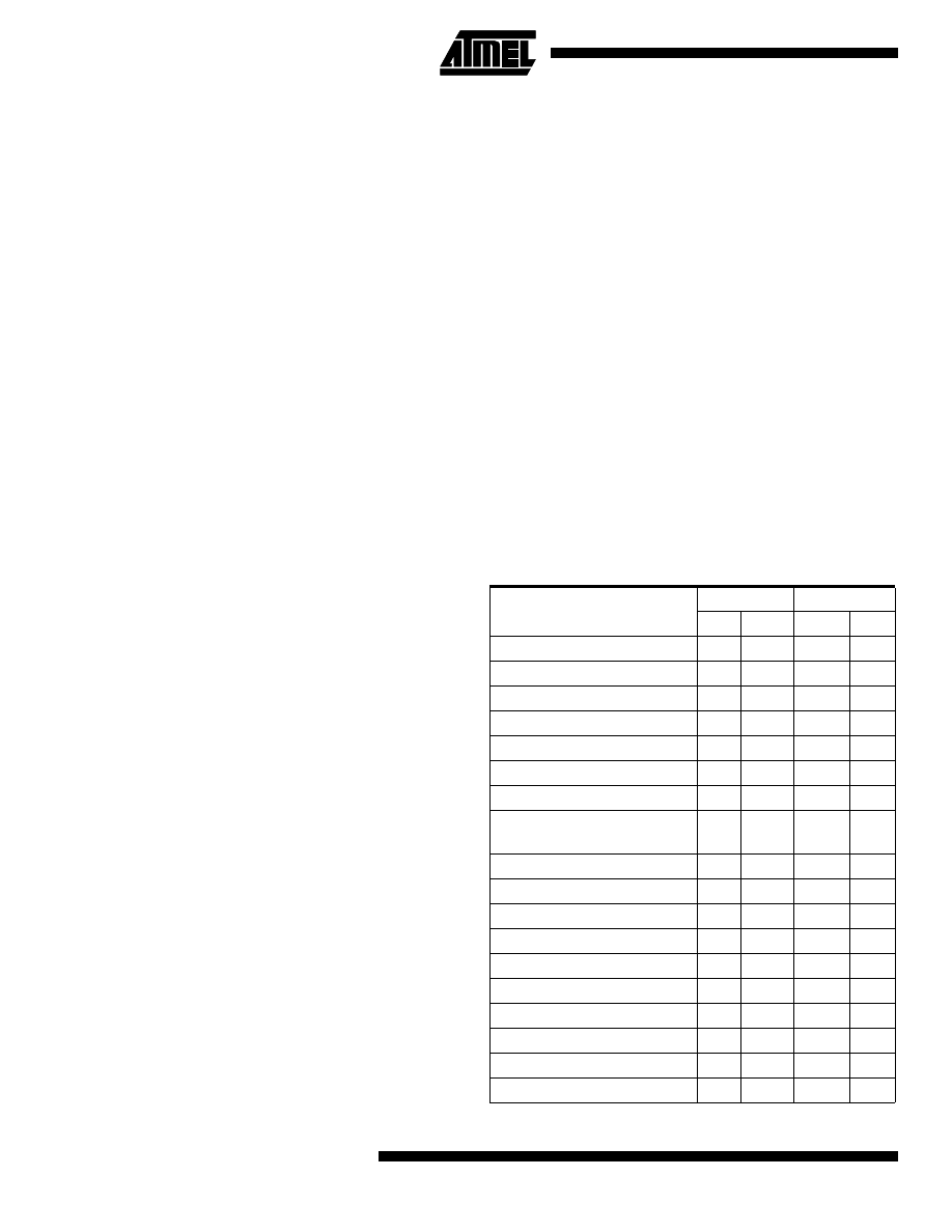
Table 1. AVRProg Commands
Host Writes
Host Reads
ID
Data
Data
Enter Programming Mode
“P”
13d
Auto Increment Address
“a”
dd
Set Address
“A”
ah al
13d
Write Program Memory, Low Byte
“c”
dd
13d
Write Program Memory, High Byte
“C”
dd
13d
Issue Page Write
“m”
13d
Read Lock Bits
“‘r”
dd
Read Program Memory
“R”
dd
(dd)
Read Data Memory
“d”
dd
Write Data Memory
“D”
dd
13d
Chip Erase
“e”
13d
Write Lock Bits
“l”
dd
13d
Write Fuse Bits
“f”
dd
13d
Read Fuse Bits
“F”
dd
Read High Fuse Bits
“N”
dd
Leave Programming Mode
“L”
13d
Select Device Type
“T”
dd
13d
Read Signature Bytes
“s”
3*dd
AVR109
3
When AVRprog.exe is executed, it searches for any sup-
ported programmers on the available COM ports. It uses
19.2 kbps 8N1 (8 databits, no parity bits and one stopbit)
communication; the receiving UART should for this reason
be configured to this speed and mode.
Assuming communication with an ATmega161, the
sequence for determining programmer type is as follows:
AVRprog :4 ’ESC’: flushing the UART buffers.
AVRprog :’S’ to get software identifier
MegaAVR :’AVRB161’ (boot loader). AVRprog accepts
any string consisting of seven characters starting
with the three characters ’AVR’.
AVRprog :’a’ to ask for auto address incrementing
megaAVR :’y’ (Yes)
AVRprog :’t’ to ask for supported devices?
megaAVR :’60’ for mega161 and ’00’ to indicate end
of list
AVRprog :’T’ and ’60’ to tell programmer that
ATmega161 is selected
AVRprog :’y’ +dd ’y’ +dd ’y’ +dd ’x’ +dd to activate
LEDs.
The sequence for programming is as follows:
AVRprog :3 ’ESC’: flushing the UART buffers.
AVRprog :’T’ and ’60’ to tell programmer that
ATmega161 is selected
AVRprog :’P’ to enable programming
AVRprog :’e’ to erase application area
AVRprog :’P’ to enable programming
AVRprog :’A’ to set address=0x0000
AVRprog :’A’ to set address to start programming
from
AVRprog :’c’ to send low data byte
AVRprog :’C’ to send high data byte
When the temporary buffer is full:
AVRprog :’A’ to set address of page
AVRprog :’m’ to write page
Then continues with:
AVRprog :’c’ to send low data byte
AVRprog :’C’ to send high data byte
Repeated until all data sent:
When all data is transferred
AVRprog :’A’ to set address of last page
AVRprog :’m’ to write last page
AVRprog :’L’ to leave programming mode
Data is then verified by executing the following sequence:
AVRprog :’P’ to enable programming
AVRprog :’A’ to set address
AVRprog :’R’ to read program memory
ATmega161:two bytes containing program data.
AVRprog continues sending “R” until all data is read and
finishes the sequence by sending “L” to leave programming
mode.
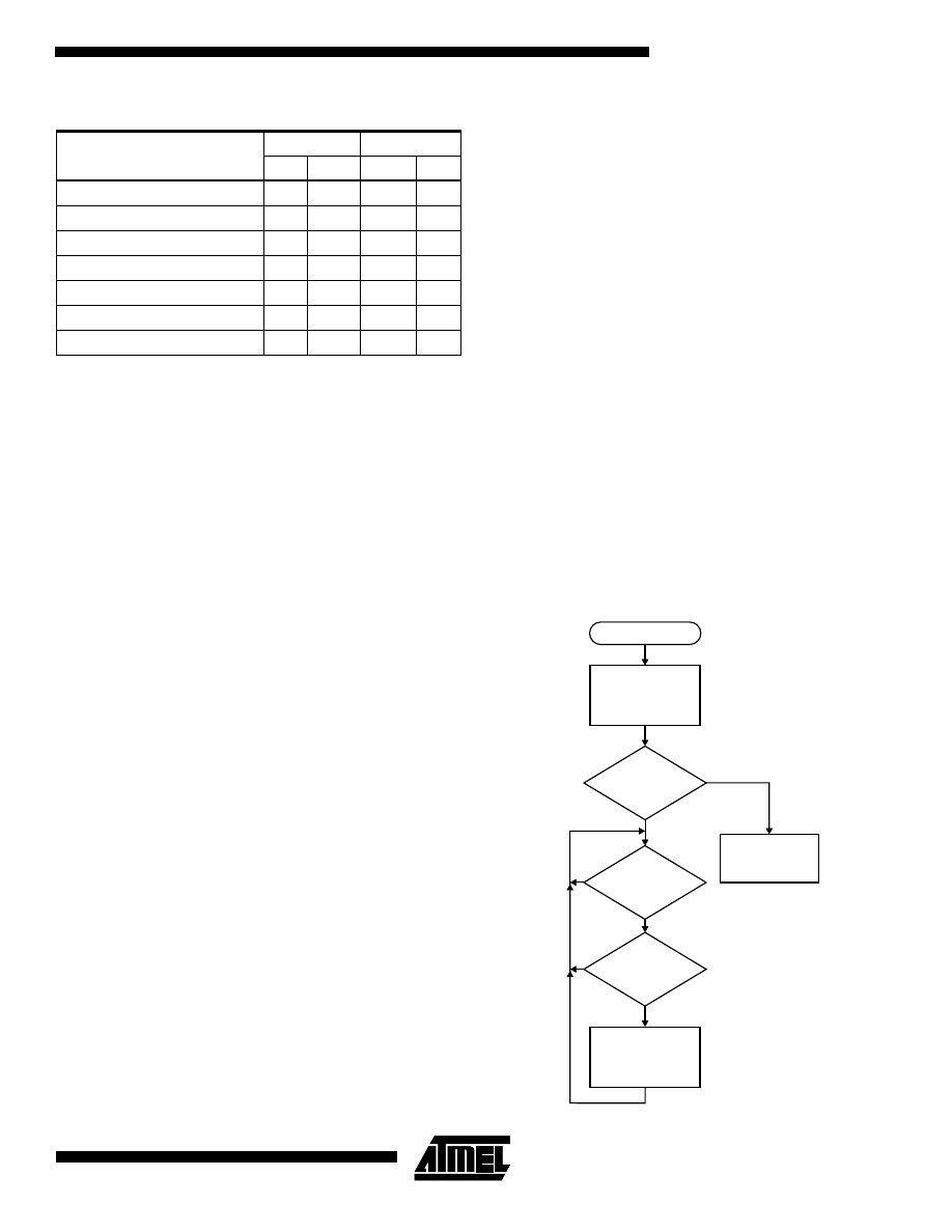
Program Description
The main program starts by checking if programming is to
be done, or if the program in the Application Code Section
is to be executed. In this application this is indicated by the
value of register PIND. If a user-specified pin on port D is
held low during reset, the program enters programming
mode (the pin can be selected in the main.c source code).
If this pin is high, program execution starts from address
$0000 (as if an ordinary reset had occurred).
Figure 2. Main Program Execution
Return Supported Device Codes
“t”
n*dd
00d
Return Software Identifier
“S”
s[7]
Return Software Version
“V”
dd dd
Return Hardware Version
“v”
dd dd
Return Programmer Type
“p”
dd
Set LED
“x”
dd
13d
Clear LED
“y”
dd
13d
Table 1. AVRProg Commands (Continued)
Host Writes
Host Reads
ID
Data
Data
Execute program
in Application
Code Section.
Start
Init PORTD.
PinD,x
low?
Command
received?
Valid
command?
Execute associated
task.
Yes
No
No
No

AVR109
4
In programming mode, the program receives commands
from AVRprog via the UART. Each command executes an
associated task. This program does not use the LED com-
mands but the command is implemented in order to
prevent AVRprog from losing synchronization. Any com-
mand not recognized by the Boot Loader program results in
a “?” being sent back to AVRprog.
Main.c
The main.c program handles communication with the host
PC and executes the received commands. Figure 2 shows
a flowchart illustrating the operation.
Note:
As shown in Figure 2, once the Boot Loader routine is
entered, the only way to exit is through a reset of the
device.
Serial.c
The UART routine (serial.c) implements simple polled
UART routines. As described earlier, the reason for doing
this polled is that for certain Boot Lock Bit settings, inter-
rupts are not permitted in the boot section.
Assembly.s90
All routines using SPM are written in assembly. This is
done in order to avoid conflicts in the code. The SPM com-
mands require data to be placed in both the Z register
(r31:r30) and in the r1:r0 register pair. This could be done
in C code, but writing in assembly simplifies the task of con-
trolling these register pairs and reduces overhead C code.
Calling the Assembly Routines
Two of the assembly routines have dual functions, depend-
ing on the second argument sent to them:
void write_page (unsigned int addr, unsigned char
function
);
The first argument is the address of the page to write. The
second argument indicates the function to be performed.
Function = 0x05 results in writing the page to program
memory. Function = 0x03 results in erasing the page.
unsigned int read_program_memory(unsigned int addr,
unsigned char function);
In this function the first argument is the address of the page
to read. The second argument indicates the function to be
performed. If function = 0x00, the routine returns the pro-
gram data in the specified location. If function = 0x09 and
address = 0x0000, 0x0001 or 0x0003, the routine returns
the fuse, lock bits or the fuse high bits, respectively. In this
case, the main program ignores the 8MSB of the returned
integer.
Below is a listing of the assembly part of the program.
NAME
assembly(16)
RSEG
CODE(0)
RSEG
UDATA0(0)
PUBLIC
fill_temp_buffer
PUBLIC
write_page
PUBLIC
write_lock_bits
PUBLIC read_program_memory
EXTERN
?CL0T_1_40_L08
RSEG
CODE
#include "iom161.h"
write_page:
MOV R31,R17
MOV R30,R16
;move address to z pointer (R31=ZH
R30=ZL)
OUT SPMCR,R20 ;argument 2 decides function
SPM
;perform pagewrite
RET
fill_temp_buffer:
MOV R31,R21
MOV R30,R20 ;move address to z pointer (R31=ZH
R30=ZL)
MOV R1,R17
MOV R0,R16 ;move data to reg 0 and 1
LDI R18,0x01
OUT SPMCR,R16
SPM
;Store program memory
RET
read_program_memory:
MOV R31,R17
;R31=ZH R30=ZL
MOV R30,R16
;move address to z pointer
SBRC R20,0
;read lockbits? (second
argument=0x09)
OUT SPMEN,R20 ;if so, place second argument in
SPMEN register
LPM ;read
LSB
MOV R16,R0
INC R30
LPM
MOV R17,R0
;read MSB (ignored when reading
lockbits)
RET
write_lock_bits:
MOV R0,R16
LDI R17,0x09
OUT SPMCR,R17
SPM ;write
lockbits
RET
END

AVR109
5
Special Considerations
1.
In the ATmega161and ATmega163 the Boot Loader
section stretches from $3C00-$3FFF ($1E00-
$1FFF when counting words) so the linker file must
be modified to place the program in these locations.
Change the “Program address space” line to:
// Program address space (internal Flash memory)
-
Z(CODE)INTVEC,RCODE,CDATA0,CDATA1,CCSTR,SWITCH,FLA
SH,CODE=3C00-3FFF
This will place the code in the boot block. In addition,
the BOOTRST fuse must be programmed in order to
move the reset vector to $1E00.
2.
The Boot Loader program must have a way to
determine if it shall enter programming mode or run
the program residing in the application code
section.
This is implemented by doing a check to see if a spe-
cific I/O pin is held low during power-up. If all pins are
high, the Boot Loader program executes a software
jump to address $0000 and starts executing the appli-
cation code. This jump can be implemented by defining
a function pointer pointing to address $0000,
void (*funcptr)( void ) = 0x0000; // Set up
function pointer
and then execute the jump by calling this pointer:
funcptr();
3.
If the pin is pulled low, programming mode is
entered. It’s not possible to exit programming mode.
To return to normal operation, the pin should be
released and the device reset. After a reset, the port
is by default configured as an input with internal
pull-up disabled. The selected pin should be pulled
high by an external pull-up resistor.
4.
Depending on the state of the Boot Lock Bits, inter-
rupts may or may not be available when executing
instructions from the Flash Boot Section. For this
reason, the UART routines implemented in this
application note use polling instead of interrupts.
5.
The SPM operations utilize the Z register to indicate
page address/temp buffer address. This register is
also used as a data pointer by the IAR C compiler.
This causes conflicts and therefore all sequences
dealing with SPM are written in assembly, thereby
achieving full control over register use.
6.
It takes overhead code to gain direct control over
registers writing in C. This is also a reason why all
routines dealing with SPM are written in assembly.
7.
The program is optimized for size. It is 504 bytes
and will therefore fit in all parts that have a Boot
Loader section of 512 bytes or more.
In order to reduce the code size, a number of optimizations
have been done:
• “If then else if” statements are used instead of case.
• For(;;) {} is used instead of while(1){}.
• In the CSTARTUP.S90 file, all unused references
have been deleted. That includes all references to
“__low_level_init”, all “#if #endif” statements and the
C_EXIT module.
• All variables are implemented using the smallest data
type possible.
• Unsigned datatypes are used where this is possible.
8.
See application note “AVR035: Efficient C Coding
for AVR” for more details on efficient C
programming.

© Atmel Corporation 2000.
Atmel Corporation makes no warranty for the use of its products, other than those expressly contained in the Company’s standard war-
ranty which is detailed in Atmel’s Terms and Conditions located on the Company’s web site. The Company assumes no responsibility for
any errors which may appear in this document, reserves the right to change devices or specifications detailed herein at any time without
notice, and does not make any commitment to update the information contained herein. No licenses to patents or other intellectual prop-
erty of Atmel are granted by the Company in connection with the sale of Atmel products, expressly or by implication. Atmel’s products are
not authorized for use as critical components in life suppor t devices or systems.
Atmel Headquarters
Atmel Operations
Corporate Headquarters
2325 Orchard Parkway
San Jose, CA 95131
TEL (408) 441-0311
FAX (408) 487-2600
Europe
Atmel U.K., Ltd.
Coliseum Business Centre
Riverside Way
Camberley, Surrey GU15 3YL
England
TEL (44) 1276-686-677
FAX (44) 1276-686-697
Asia
Atmel Asia, Ltd.
Room 1219
Chinachem Golden Plaza
77 Mody Road Tsimhatsui
East Kowloon
Hong Kong
TEL (852) 2721-9778
FAX (852) 2722-1369
Japan
Atmel Japan K.K.
9F, Tonetsu Shinkawa Bldg.
1-24-8 Shinkawa
Chuo-ku, Tokyo 104-0033
Japan
TEL (81) 3-3523-3551
FAX (81) 3-3523-7581
Atmel Colorado Springs
1150 E. Cheyenne Mtn. Blvd.
Colorado Springs, CO 80906
TEL (719) 576-3300
FAX (719) 540-1759
Atmel Rousset
Zone Industrielle
13106 Rousset Cedex
France
TEL (33) 4-4253-6000
FAX (33) 4-4253-6001
Fax-on-Demand
North America:
1-(800) 292-8635
International:
1-(408) 441-0732
literature@atmel.com
Web Site
http://www.atmel.com
BBS
1-(408) 436-4309
Printed on recycled paper.
1644A–03/00/xM
Marks bearing
®
and/or
™
are registered trademarks and trademarks of Atmel Corporation.
Terms and product names in this document may be trademarks of others.
Document Outline
- Features
- Introduction
- SPM Explained
- Memory Organization
- Security Issues
- Protocol
- Program Description
- Special Considerations
Wyszukiwarka
Podobne podstrony:
Atmel Avr USB Firmware Upgrade For AT90USB doc7769
Atmel AVR Assembler id 71678 Nieznany (2)
AVR i ARM7 Programowanie mikrokontrolerow dla kazdego avrar7
Zapoznanie z AVR i pierwsze programy
Programator AVR (STK200) Progra Nieznany
Atmel Avr Efficient C Coding
Atmel Avr USB Firmware Upgrade For AT90USB doc7769
Atmel AVR Assembler id 71678 Nieznany (2)
Geschwindigkeit ist keine Hexerei Experimente mit dem ATMEL AVR RISC Prozessor
Atmel Avr USB Software Library for AT90USBxxx Microcontrollers doc7675
ATMEL AVR ISP Original Adapter Schematics
current supply Atmel AVR based Constant Current Supply
lee mentire Success Self Programming
więcej podobnych podstron