
Atmel AVR Assembler
Page 1 of 20
file://C:\Documents and Settings\eivind\Local Settings\Temp\~hhF071.htm
20.02.2003
AVR Assembler Help
Welcome to the ATMEL AVR Assembler.
z
What's New
z
Known Issues
Please select between the following Help items:
z
General information gives general information about the Assembler
z
Assembler source gives a brief description of what a source file looks like
z
Instruction mnemonics describes the AVR Instruction set
{
Arithmetic and Logic Instructions
{
Branch Instructions
{
Data Transfer Instructions
{
Bit and Bit-test Instructions
z
Assembler directives gives a description of the directives
z
Expressions describes how to make constant expressions
{
Expression operands
{
Expression operators
{
Functions in expressions
The Assembler is supplied as a MS-DOS command line program that can be used stand-alone or
automatically invoked by AVR Studio. A description of how to use the Command line Assembler
is included in this help file
Device specific instruction set summaries:
The actual instruction set varies between the devices. Use these links to verify the instruction set
for the desired device.
z
AT90S1200
z
AT90S2313
z
AT90S2323 and AT90S2343
z
AT90S2333 and AT90S4433
z
AT90S4414 and AT90S8515
z
AT90S4434 and AT90S8535
z
AT90C8534
z
ATtiny10, ATtiny11 and ATtiny12
z
ATtiny15
z
ATtiny22
z
ATtiny26
z
ATtiny28
z
ATmega8/8515/8535
z
ATmega16
z
ATmega161
z
ATmega162
z
ATmega163
z
ATmega169
z
ATmega32
z
ATmega323
z
ATmega103

Atmel AVR Assembler
Page 2 of 20
file://C:\Documents and Settings\eivind\Local Settings\Temp\~hhF071.htm
20.02.2003
z
ATmega64/128
New for this release (avrasm v1.56):
Added device directives for ATmega162, ATmega169, ATmega8515, ATmega8535, ATtiny26
and AT86RF401.
What's New
AVR Assembler v1.56 date 30-apr-2002
z
Included device directives for ATmega162, ATmega169, ATmega8515, ATmega8535,
ATtiny26, AT86RF401.
z
Added *.def.inc files for the above mentioned devices.
General information
The Assembler translates assembly source code into object code. The generated object code can
be used as input to a simulator such as the ATMEL AVR Simulator or an emulator such as the
ATMEL AVR In-Circuit Emulator. The Assembler also generates a PROMable code which can
be programmed directly into the program memory of an AVR microcontroller
The Assembler generates fixed code allocations, consequently no linking is necessary.
The instruction set of the AVR family of microcontrollers is only briefly described, refer to the
AVR Data Book in order to get more detailed knowledge of the instruction set for the different
microcontrollers.
Assembler source
The Assembler works on source files containing instruction mnemonics, labels and directives.
The instruction mnemonics and the directives often take operands.
Code lines should be limited to 120 characters.
Every input line can be preceded by a label, which is an alphanumeric string terminated by a
colon. Labels are used as targets for jump and branch instructions and as variable names in
Program memory and RAM.
An input line may take one of the four following forms:
[label:] directive [operands] [Comment]
[label:] instruction [operands] [Comment]
Comment
Empty line
A comment has the following form:
; [Text]
Atmel AVR Assembler
Page 3 of 20
file://C:\Documents and Settings\eivind\Local Settings\Temp\~hhF071.htm
20.02.2003
Items placed in braces are optional. The text between the comment-delimiter (;) and the end of
line (EOL) is ignored by the Assembler. Labels, instructions and directives are described in more
detail later.
Examples:
label: .EQU var1=100 ; Set var1 to 100 (Directive)
.EQU var2=200 ; Set var2 to 200
test: rjmp test ; Infinite loop (Instruction)
; Pure comment line
; Another comment line
Note that there are no restrictions with respect to column placement of labels, directives,
comments or instructions.
Instruction mnemonics
The Assembler accepts mnemonic instructions from the instruction set. A summary of the
instruction set mnemonics and their parameters is given here. For a detailed description of the
Instruction set, refer to the AVR Data Book.
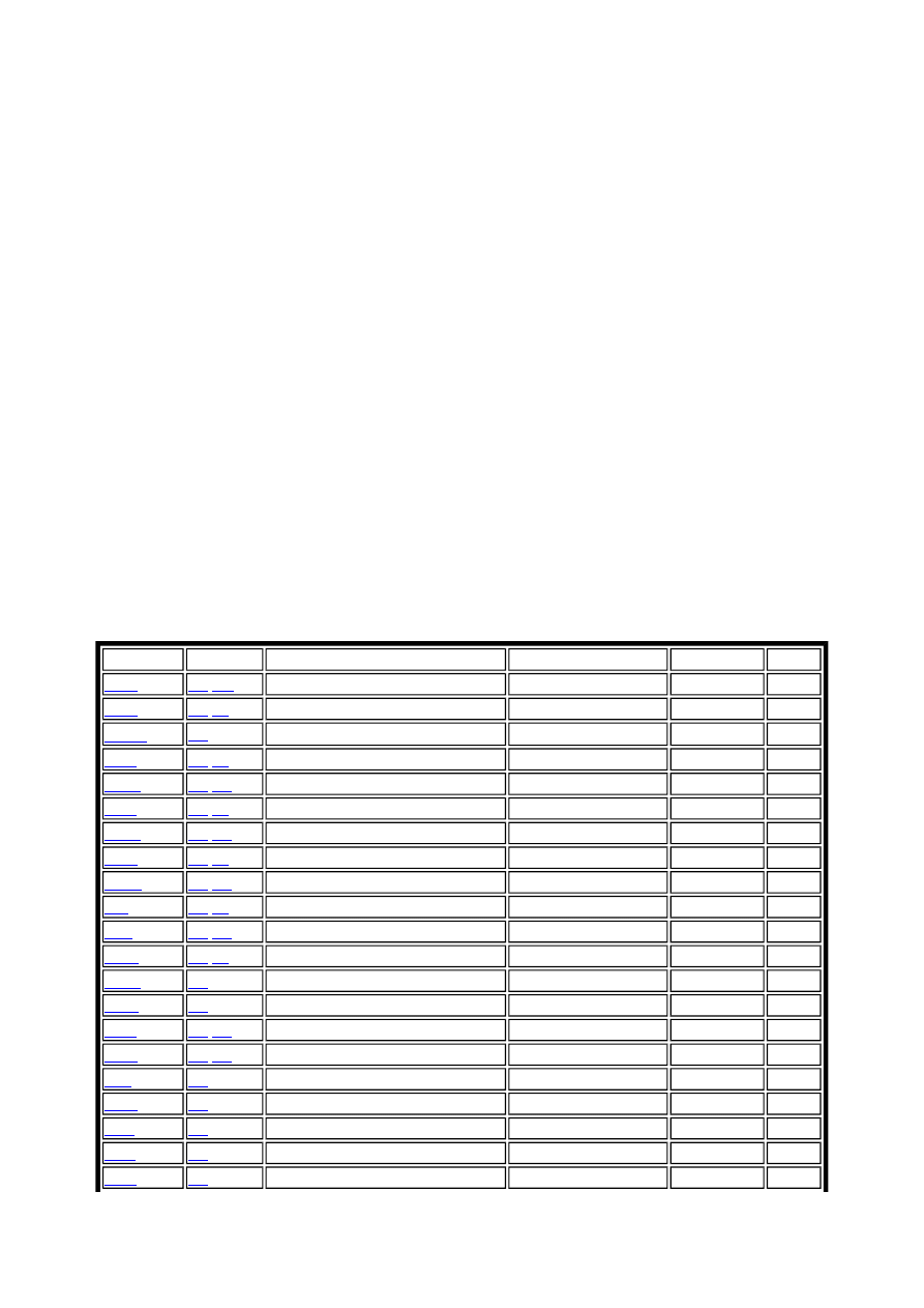
Arithmetic and Logic Instructions
Mnemonic Operands Description
Operation
Flags
Cycles
ADD
Rd
,
Rr
Add without Carry
Rd = Rd + Rr
Z,C,N,V,H,S 1
ADC
Rd
,
Rr
Add with Carry
Rd = Rd + Rr + C
Z,C,N,V,H,S 1
ADIW
Rd
, K
Add Immediate To Word
Rd+1:Rd,K
Z,C,N,V,S
2
SUB
Rd
,
Rr
Subtract without Carry
Rd = Rd - Rr
Z,C,N,V,H,S 1
SUBI
Rd
,
K8
Subtract Immediate
Rd = Rd - K8
Z,C,N,V,H,S 1
SBC
Rd
,
Rr
Subtract with Carry
Rd = Rd - Rr - C
Z,C,N,V,H,S 1
SBCI
Rd
,
K8
Subtract with Carry Immedtiate
Rd = Rd - K8 - C
Z,C,N,V,H,S 1
AND
Rd
,
Rr
Logical AND
Rd = Rd · Rr
Z,N,V,S
1
ANDI
Rd
,
K8
Logical AND with Immediate
Rd = Rd · K8
Z,N,V,S
1
OR
Rd
,
Rr
Logical OR
Rd = Rd V Rr
Z,N,V,S
1
ORI
Rd
,
K8
Logical OR with Immediate
Rd = Rd V K8
Z,N,V,S
1
EOR
Rd
,
Rr
Logical Exclusive OR
Rd = Rd EOR Rr
Z,N,V,S
1
COM
Rd
One's Complement
Rd = $FF - Rd
Z,C,N,V,S
1
NEG
Rd
Two's Complement
Rd = $00 - Rd
Z,C,N,V,H,S 1
SBR
Rd
,
K8
Set Bit(s) in Register
Rd = Rd V K8
Z,C,N,V,S
1
CBR
Rd
,
K8
Clear Bit(s) in Register
Rd = Rd · ($FF - K8)
Z,C,N,V,S
1
INC
Rd
Increment Register
Rd = Rd + 1
Z,N,V,S
1
DEC
Rd
Decrement Register
Rd = Rd -1
Z,N,V,S
1
TST
Rd
Test for Zero or Negative
Rd = Rd · Rd
Z,C,N,V,S
1
CLR
Rd
Clear Register
Rd = 0
Z,C,N,V,S
1
SER
Rd
Set Register
Rd = $FF
None
1
Atmel AVR Assembler
Page 4 of 20
file://C:\Documents and Settings\eivind\Local Settings\Temp\~hhF071.htm
20.02.2003
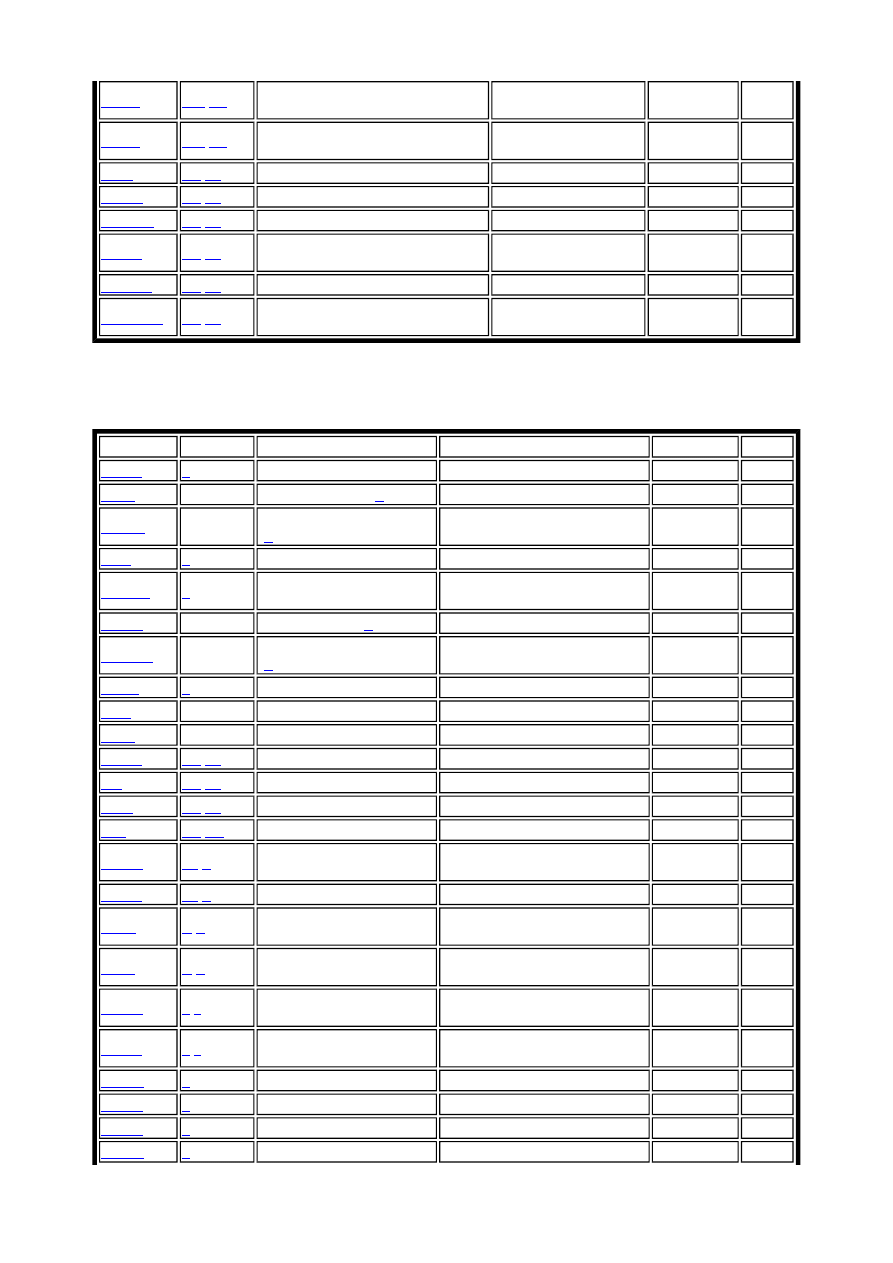
Branch Instructions
ADIW
Rdl
,
K6
Add Immediate to Word
Rdh:Rdl = Rdh:Rdl +
K6
Z,C,N,V,S
2
SBIW
Rdl
,
K6
Subtract Immediate from Word
Rdh:Rdl = Rdh:Rdl - K
6
Z,C,N,V,S
2
MUL
Rd
,
Rr
Multiply Unsigned
R1:R0 = Rd * Rr
Z,C
2
MULS
Rd
,
Rr
Multiply Signed
R1:R0 = Rd * Rr
Z,C
2
MULSU
Rd
,
Rr
Multiply Signed with Unsigned
R1:R0 = Rd * Rr
Z,C
2
FMUL
Rd
,
Rr
Fractional Multiply Unsigned
R1:R0 = (Rd * Rr) <<
1
Z,C
2
FMULS
Rd
,
Rr
Fractional Multiply Signed
R1:R0 = (Rd *Rr) << 1 Z,C
2
FMULSU
Rd
,
Rr
Fractional Multiply Signed with
Unsigned
R1:R0 = (Rd * Rr) <<
1
Z,C
2
Mnemonic Operands Description
Operation
Flags
Cycles
RJMP
k
Relative Jump
PC = PC + k +1
None
2
IJMP
None
Indirect Jump to (
Z
)
PC = Z
None
2
EIJMP
None
Extended Indirect Jump
(
Z
)
STACK = PC+1, PC(15:0) = Z,
PC(21:16) = EIND
None
2
JMP
k
Jump
PC = k
None
3
RCALL
k
Relative Call Subroutine
STACK = PC+1, PC = PC + k
+ 1
None
3/4*
ICALL
None
Indirect Call to (
Z
)
STACK = PC+1, PC = Z
None
3/4*
EICALL
None
Extended Indirect Call to
(
Z
)
STACK = PC+1, PC(15:0) = Z,
PC(21:16) =EIND
None
4*
CALL
k
Call Subroutine
STACK = PC+2, PC = k
None
4/5*
RET
None
Subroutine Return
PC = STACK
None
4/5*
RETI
None
Interrupt Return
PC = STACK
I
4/5*
CPSE
Rd
,
Rr
Compare, Skip if equal
if (Rd ==Rr) PC = PC 2 or 3
None
1/2/3
CP
Rd
,
Rr
Compare
Rd -Rr
Z,C,N,V,H,S 1
CPC
Rd
,
Rr
Compare with Carry
Rd - Rr - C
Z,C,N,V,H,S 1
CPI
Rd
,
K8
Compare with Immediate Rd - K
Z,C,N,V,H,S 1
SBRC
Rr
,
b
Skip if bit in register
cleared
if(Rr(b)==0) PC = PC + 2 or 3 None
1/2/3
SBRS
Rr
,
b
Skip if bit in register set
if(Rr(b)==1) PC = PC + 2 or 3 None
1/2/3
SBIC
P
,
b
Skip if bit in I/O register
cleared
if(I/O(P,b)==0) PC = PC + 2 or
3
None
1/2/3
SBIS
P
,
b
Skip if bit in I/O register
set
if(I/O(P,b)==1) PC = PC + 2 or
3
None
1/2/3
BRBC
s
,
k
Branch if Status flag
cleared
if(SREG(s)==0) PC = PC + k +
1
None
1/2
BRBS
s
,
k
Branch if Status flag set
if(SREG(s)==1) PC = PC + k +
1
None
1/2
BREQ
k
Branch if equal
if(Z==1) PC = PC + k + 1
None
1/2
BRNE
k
Branch if not equal
if(Z==0) PC = PC + k + 1
None
1/2
BRCS
k
Branch if carry set
if(C==1) PC = PC + k + 1
None
1/2
BRCC
k
Branch if carry cleared
if(C==0) PC = PC + k + 1
None
1/2
Atmel AVR Assembler
Page 5 of 20
file://C:\Documents and Settings\eivind\Local Settings\Temp\~hhF071.htm
20.02.2003
* Cycle times for data memory accesses assume internal memory accesses, and are not valid for
accesses through the external RAM interface. For the instructions CALL, ICALL, EICALL,
RCALL, RET and RETI, add three cycles plus two cycles for each wait state in devices with up
to 16 bit PC (128KB program memory). For devices with more than 128KB program memory,
add five cycles plus three cycles for each wait state.
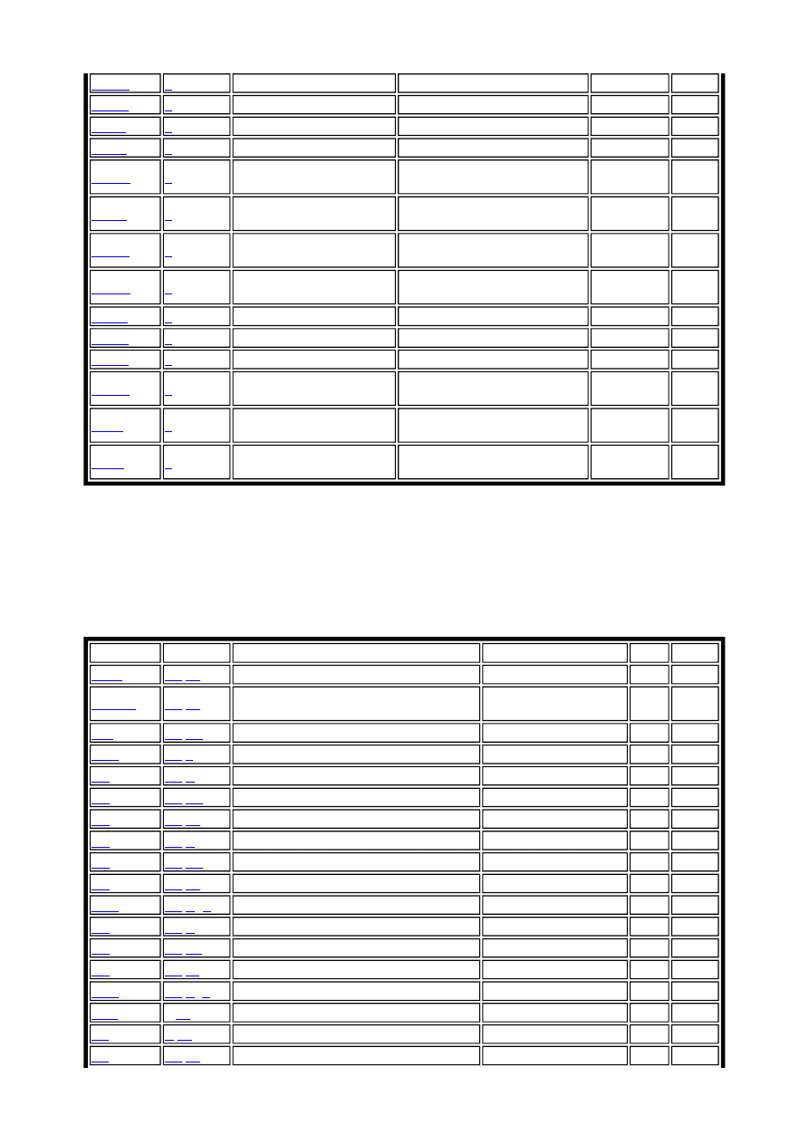
Data Transfer Instructions
BRSH
k
Branch if same or higher
if(C==0) PC = PC + k + 1
None
1/2
BRLO
k
Branch if lower
if(C==1) PC = PC + k + 1
None
1/2
BRMI
k
Branch if minus
if(N==1) PC = PC + k + 1
None
1/2
BRPL
k
Branch if plus
if(N==0) PC = PC + k + 1
None
1/2
BRGE
k
Branch if greater than or
equal (signed)
if(S==0) PC = PC + k + 1
None
1/2
BRLT
k
Branch if less than
(signed)
if(S==1) PC = PC + k + 1
None
1/2
BRHS
k
Branch if half carry flag
set
if(H==1) PC = PC + k + 1
None
1/2
BRHC
k
Branch if half carry flag
cleared
if(H==0) PC = PC + k + 1
None
1/2
BRTS
k
Branch if T flag set
if(T==1) PC = PC + k + 1
None
1/2
BRTC
k
Branch if T flag cleared
if(T==0) PC = PC + k + 1
None
1/2
BRVS
k
Branch if overflow flag set if(V==1) PC = PC + k + 1
None
1/2
BRVC
k
Branch if overflow flag
cleared
if(V==0) PC = PC + k + 1
None
1/2
BRIE
k
Branch if interrupt
enabled
if(I==1) PC = PC + k + 1
None
1/2
BRID
k
Branch if interrupt
disabled
if(I==0) PC = PC + k + 1
None
1/2
Mnemonic Operands Description
Operation
Flags Cycles
MOV
Rd
,
Rr
Copy register
Rd = Rr
None 1
MOVW
Rd
,
Rr
Copy register pair
Rd+1:Rd = Rr+1:Rr, r,d
even
None 1
LDI
Rd
,
K8
Load Immediate
Rd = K
None 1
LDS
Rd
,
k
Load Direct
Rd = (k)
None 2*
LD
Rd
,
X
Load Indirect
Rd = (X)
None 2*
LD
Rd
,
X+
Load Indirect and Post-Increment
Rd = (X), X=X+1
None 2*
LD
Rd
,
-X
Load Indirect and Pre-Decrement
X=X-1, Rd = (X)
None 2*
LD
Rd
,
Y
Load Indirect
Rd = (Y)
None 2*
LD
Rd
,
Y+
Load Indirect and Post-Increment
Rd = (Y), Y=Y+1
None 2*
LD
Rd
,
-Y
Load Indirect and Pre-Decrement
Y=Y-1, Rd = (Y)
None 2*
LDD
Rd
,
Y
+
q
Load Indirect with displacement
Rd = (Y+q)
None 2*
LD
Rd
,
Z
Load Indirect
Rd = (Z)
None 2*
LD
Rd
,
Z+
Load Indirect and Post-Increment
Rd = (Z), Z=Z+1
None 2*
LD
Rd
,
-Z
Load Indirect and Pre-Decrement
Z=Z-1, Rd = (Z)
None 2*
LDD
Rd
,
Z
+
q
Load Indirect with displacement
Rd = (Z+q)
None 2*
STS
k,
Rr
Store Direct
(k) = Rr
None 2*
ST
X
,
Rr
Store Indirect
(X) = Rr
None 2*
ST
X+
,
Rr
Store Indirect and Post-Increment
(X) = Rr, X=X+1
None 2*
Atmel AVR Assembler
Page 6 of 20
file://C:\Documents and Settings\eivind\Local Settings\Temp\~hhF071.htm
20.02.2003
* Cycle times for data memory accesses assume internal memory accesses and are not valid for
accesses through the external RAM interface. For the LD, ST, LDD, STD, LDS, STS, PUSH and
POP instructions, add one cycle plus one cycle for each wait state.
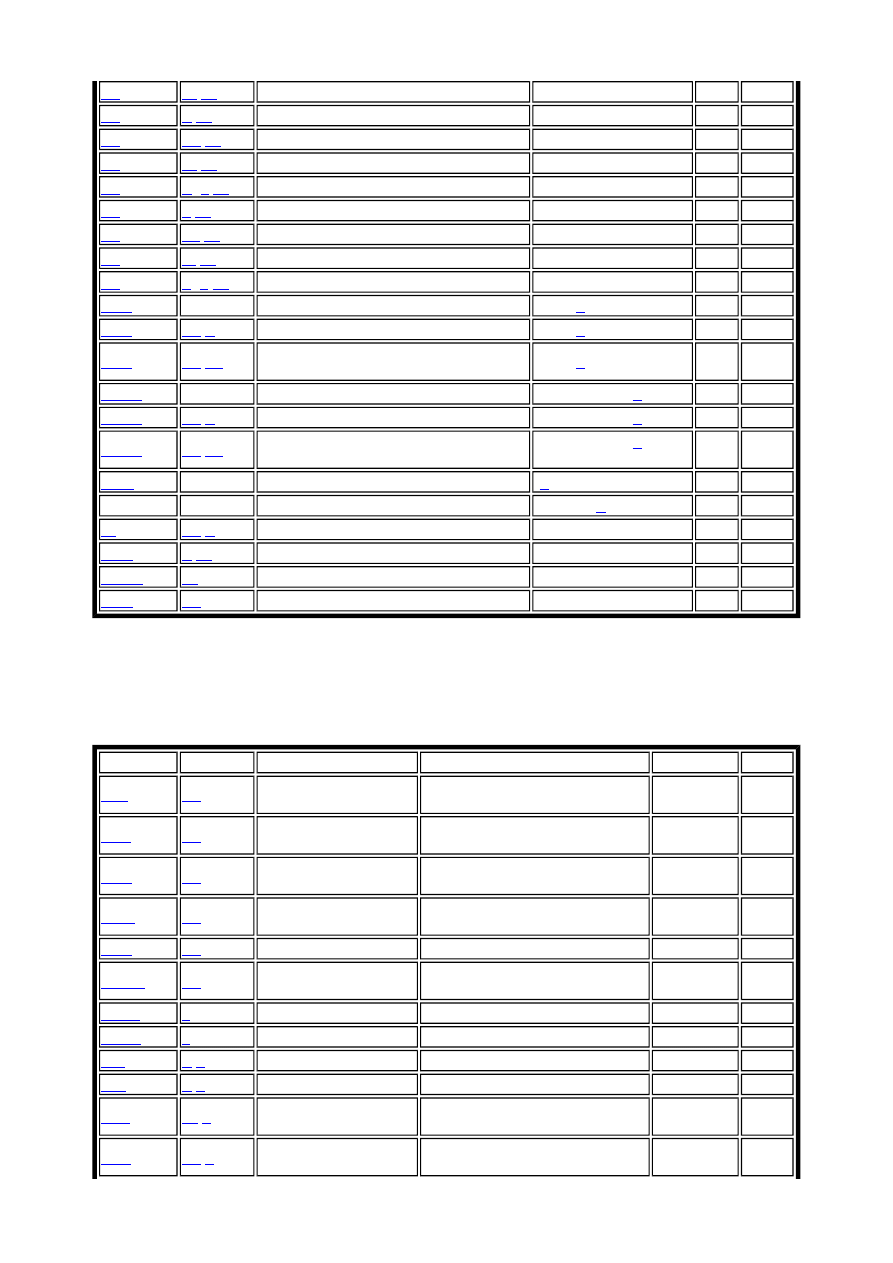
Bit and Bit-test Instructions
ST
-X
,
Rr
Store Indirect and Pre-Decrement
X=X-1, (X)=Rr
None 2*
ST
Y
,
Rr
Store Indirect
(Y) = Rr
None 2*
ST
Y+
,
Rr
Store Indirect and Post-Increment
(Y) = Rr, Y=Y+1
None 2
ST
-Y
,
Rr
Store Indirect and Pre-Decrement
Y=Y-1, (Y) = Rr
None 2
ST
Y
+
q
,
Rr
Store Indirect with displacement
(Y+q) = Rr
None 2
ST
Z
,
Rr
Store Indirect
(Z) = Rr
None 2
ST
Z+
,
Rr
Store Indirect and Post-Increment
(Z) = Rr, Z=Z+1
None 2
ST
-Z
,
Rr
Store Indirect and Pre-Decrement
Z=Z-1, (Z) = Rr
None 2
ST
Z
+
q
,
Rr
Store Indirect with displacement
(Z+q) = Rr
None 2
LPM
None
Load Program Memory
R0 = (
Z
)
None 3
LPM
Rd
,
Z
Load Program Memory
Rd = (
Z
)
None 3
LPM
Rd
,
Z+
Load Program Memory and Post-
Increment
Rd = (
Z
), Z=Z+1
None 3
ELPM
None
Extended Load Program Memory
R0 = (RAMPZ:
Z
)
None 3
ELPM
Rd
,
Z
Extended Load Program Memory
Rd = (RAMPZ:
Z
)
None 3
ELPM
Rd
,
Z+
Extended Load Program Memory and
Post Increment
Rd = (RAMPZ:
Z
), Z =
Z+1
None 3
SPM
None
Store Program Memory
(
Z
) = R1:R0
None -
ESPM
None
Extended Store Program Memory
(RAMPZ:
Z
) = R1:R0
None -
IN
Rd
,
P
In Port
Rd = P
None 1
OUT
P
,
Rr
Out Port
P = Rr
None 1
PUSH
Rr
Push register on Stack
STACK = Rr
None 2
POP
Rd
Pop register from Stack
Rd = STACK
None 2
Mnemonic Operands Description
Operation
Flags
Cycles
LSL
Rd
Logical shift left
Rd(n+1)=Rd(n), Rd(0)=0, C=Rd
(7)
Z,C,N,V,H,S 1
LSR
Rd
Logical shift right
Rd(n)=Rd(n+1), Rd(7)=0, C=Rd
(0)
Z,C,N,V,S
1
ROL
Rd
Rotate left through
carry
Rd(0)=C, Rd(n+1)=Rd(n), C=Rd
(7)
Z,C,N,V,H,S 1
ROR
Rd
Rotate right through
carry
Rd(7)=C, Rd(n)=Rd(n+1), C=Rd
(0)
Z,C,N,V,S
1
ASR
Rd
Arithmetic shift right
Rd(n)=Rd(n+1), n=0,...,6
Z,C,N,V,S
1
SWAP
Rd
Swap nibbles
Rd(3..0) = Rd(7..4), Rd(7..4) = Rd
(3..0)
None
1
BSET
s
Set flag
SREG(s) = 1
SREG(s)
1
BCLR
s
Clear flag
SREG(s) = 0
SREG(s)
1
SBI
P
,
b
Set bit in I/O register
I/O(P,b) = 1
None
2
CBI
P
,
b
Clear bit in I/O register I/O(P,b) = 0
None
2
BST
Rr
,
b
Bit store from register
to T
T = Rr(b)
T
1
BLD
Rd
,
b
Bit load from register to
T
Rd(b) = T
None
1
Atmel AVR Assembler
Page 7 of 20
file://C:\Documents and Settings\eivind\Local Settings\Temp\~hhF071.htm
20.02.2003
The Assembler is not case sensitive.
The operands have the following forms:
Rd: Destination (and source) register in the register file
Rr: Source register in the register file
b: Constant (0-7), can be a constant expression
s: Constant (0-7), can be a constant expression
P: Constant (0-31/63), can be a constant expression
K6; Constant (0-63), can be a constant expression
K8: Constant (0-255), can be a constant expression
k: Constant, value range depending on instruction. Can be a constant expression
q: Constant (0-63), can be a constant expression
Rdl: R24, R26, R28, R30. For ADIW and SBIW instructions
X,Y,Z: Indirect address registers (X=R27:R26, Y=R29:R28, Z=R31:R30)
Assembler directives
The Assembler supports a number of directives. The directives are not translated directly into
opcodes. Instead, they are used to adjust the location of the program in memory, define macros,
initialize memory and so on. An overview of the directives is given in the following table.
SEC
None
Set carry flag
C =1
C
1
CLC
None
Clear carry flag
C = 0
C
1
SEN
None
Set negative flag
N = 1
N
1
CLN
None
Clear negative flag
N = 0
N
1
SEZ
None
Set zero flag
Z = 1
Z
1
CLZ
None
Clear zero flag
Z = 0
Z
1
SEI
None
Set interrupt flag
I = 1
I
1
CLI
None
Clear interrupt flag
I = 0
I
1
SES
None
Set signed flag
S = 1
S
1
CLN
None
Clear signed flag
S = 0
S
1
SEV
None
Set overflow flag
V = 1
V
1
CLV
None
Clear overflow flag
V = 0
V
1
SET
None
Set T-flag
T = 1
T
1
CLT
None
Clear T-flag
T = 0
T
1
SEH
None
Set half carry flag
H = 1
H
1
CLH
None
Clear half carry flag
H = 0
H
1
NOP
None
No operation
None
None
1
SLEEP
None
Sleep
See instruction manual
None
1
WDR
None
Watchdog Reset
See instruction manual
None
1
BREAK
None
Execution Break
See instruction manual
None
1

Atmel AVR Assembler
Page 8 of 20
file://C:\Documents and Settings\eivind\Local Settings\Temp\~hhF071.htm
20.02.2003
Note that all directives must be preceded by a period.
BYTE - Reserve bytes to a variable
The BYTE directive reserves memory resources in the SRAM. In order to be able to refer to the
reserved location, the BYTE directive should be preceded by a label. The directive takes one
parameter, which is the number of bytes to reserve. The directive can only be used within a Data
Segment (see directives CSEG and DSEG). Note that a parameter must be given. The allocated
bytes are not initialized.
Syntax:
LABEL: .BYTE expression
Example:
.DSEG
var1: .BYTE 1 ; reserve 1 byte to var1
table: .BYTE tab_size ; reserve tab_size bytes
.CSEG
ldi r30,low(var1) ; Load Z register low
ldi r31,high(var1) ; Load Z register high
ld r1,Z ; Load VAR1 into register 1
CSEG - Code segment
The CSEG directive defines the start of a Code Segment. An Assembler file can consist of several
Code Segments, which are concatenated into one Code Segment when assembled. The BYTE
directive can not be used within a Code Segment. The default segment type is Code. The Code
Segments have their own location counter which is a word counter. The ORG directive can be
used to place code and constants at specific locations in the Program memory. The directive does
not take any parameters.
Syntax:
Directive
Description
BYTE
Reserve byte to a variable
CSEG
Code Segment
CSEGSIZE
Program memory size
DB
Define constant byte(s)
DEF
Define a symbolic name on a register
DEVICE
Define which device to assemble for
DSEG
Data Segment
DW
Define Constant word(s)
ENDM, ENDMACRO End macro
EQU
Set a symbol equal to an expression
ESEG
EEPROM Segment
EXIT
Exit from file
INCLUDE
Read source from another file
LIST
Turn listfile generation on
LISTMAC
Turn Macro expansion in list file on
NOLIST
Turn listfile generation off
ORG
Set program origin
SET
Set a symbol to an expression

Atmel AVR Assembler
Page 9 of 20
file://C:\Documents and Settings\eivind\Local Settings\Temp\~hhF071.htm
20.02.2003
.CSEG
Example:
.DSEG ; Start data segment
vartab: .BYTE 4 ; Reserve 4 bytes in SRAM
.CSEG ; Start code segment
const: .DW 2 ; Write 0x0002 in prog.mem.
mov r1,r0 ; Do something
CSEGSIZE - Program Memory Size
AT94K devices have a user configurable memory partition between the AVR Program memory
and the data memory. The program and data SRAM is divided into three blocks: 10K x 16
dedicated program SRAM, 4K x 8 dedicated data SRAM, and 6K x 16 or 12K x 8 configurable
SRAM which may be swapped between program and data memory spaces in 2K x 16 or 4K x 8
partitions.
This directive is used to specify the size of the program memory block.
Syntax:
.CSEGSIZE = 10 | 12 | 14 | 16
Example:
.CSEGSIZE = 12 ; Specifies the program meory size as 12K x 16
DB - Define constant byte(s) in program memory and EEPROM
The DB directive reserves memory resources in the program memory or the EEPROM memory.
In order to be able to refer to the reserved locations, the DB directive should be preceded by a
label. The DB directive takes a list of expressions, and must contain at least one expression. The
DB directive must be placed in a Code Segment or an EEPROM Segment.
The expression list is a sequence of expressions, delimited by commas. Each expression must
evaluate to a number between -128 and 255. If the expression evaluates to a negative number, the
8 bits twos complement of the number will be placed in the program memory or EEPROM
memory location.
If the DB directive is given in a Code Segment and the expressionlist contains more than one
expression, the expressions are packed so that two bytes are placed in each program memory
word. If the expressionlist contains an odd number of expressions, the last expression will be
placed in a program memory word of its own, even if the next line in the assemby code contains a
DB directive. The unused half of the program word is set to zero. A warning is given, in order to
notify the user that an extra zero byte is added to the .DB statement
Syntax:
LABEL: .DB expressionlist
Example:
.CSEG
consts: .DB 0, 255, 0b01010101, -128, 0xaa
.ESEG

Atmel AVR Assembler
Page 10 of 20
file://C:\Documents and Settings\eivind\Local Settings\Temp\~hhF071.htm
20.02.2003
const2: .DB 1,2,3
DEF - Set a symbolic name on a register
The DEF directive allows the registers to be referred to through symbols. A defined symbol can
be used in the rest of the program to refer to the register it is assigned to. A register can have
several symbolic names attached to it. A symbol can be redefined later in the program.
Syntax:
.DEF Symbol=Register
Example:
.DEF temp=R16
.DEF ior=R0
.CSEG
ldi temp,0xf0 ; Load 0xf0 into temp register
in ior,0x3f ; Read SREG into ior register
eor temp,ior ; Exclusive or temp and ior
DEVICE - Define which device to assemble for
The DEVICE directive allows the user to tell the Assembler which device the code is to be
executed on. Using this directive, a warning is issued if an instruction not supported by the
specified device occurs. If the Code Segment or EEPROM Segment are larger than supplied by
the device, a warning message is given. If the directive is not used, it is assumed that all
instructions are supported and that there are no restrictions on Program and EEPROM memory.
Syntax:
.DEVICE <device code>
Table: Device codes:
Example:
.DEVICE AT90S1200 ; Use the AT90S1200
.CSEG
Classic
Tiny
Mega
Other
AT90S120
ATtiny11
ATmega8
AT94K
AT90S2313
ATtiny12
ATmega16
AT86RF401
AT90S2323
ATtiny22
ATmega161
AT90S2333
ATtiny26
ATmega162
AT90S4414
ATmega163
AT90S4434
ATmega32
AT90S8515
ATmega323
AT90S8534
ATmega103
AT90S8535
ATmega104
AT90S2343
ATmega8515
AT90S4433
ATmega8535
ATmega64
ATmega128

Atmel AVR Assembler
Page 11 of 20
file://C:\Documents and Settings\eivind\Local Settings\Temp\~hhF071.htm
20.02.2003
push r30 ; This statement will generate a warning
; since the specified device does not
; have this instruction
Note: There has been a change of names that took effect 14.06.2001. The
following devices are affected:
Old name New name
ATmega104 ATmega128
ATmega32 ATmega323
ATmega164 ATmega16
In order NOT to break old projects, both old and new device directives are
allowed for the parts that are affected.
DSEG - Data Segment
The DSEG directive defines the start of a Data Segment. An Assembler file can consist of several
Data Segments, which are concatenated into one Data Segment when assembled. A Data Segment
will normally only consist of BYTE directives (and labels). The Data Segments have their own
location counter which is a byte counter. The ORG directive can be used to place the variables at
specific locations in the SRAM. The directive does not take any parameters.
Syntax:
.DSEG
Example:
.DSEG ; Start data segment
var1: .BYTE 1 ; reserve 1 byte to var1
table: .BYTE tab_size ; reserve tab_size bytes.
.CSEG
ldi r30,low(var1) ; Load Z register low
ldi r31,high(var1) ; Load Z register high
ld r1,Z ; Load var1 into register 1
DW - Define constant word(s) in program memory and EEPROM
The DW directive reserves memory resources in the program memory or the EEPROM memory.
In order to be able to refer to the reserved locations, the DW directive should be preceded by a
label.
The DW directive takes a list of expressions, and must contain at least one expression.
The DB directive must be placed in a Code Segment or an EEPROM Segment.
The expression list is a sequence of expressions, delimited by commas. Each expression must
evaluate to a number between -32768 and 65535. If the expression evaluates to a negative
number, the 16 bits twos complement of the number will be placed in the program memory or
EEPROM memory location.
Syntax:
LABEL: .DW expressionlist
Example:

Atmel AVR Assembler
Page 12 of 20
file://C:\Documents and Settings\eivind\Local Settings\Temp\~hhF071.htm
20.02.2003
.CSEG
varlist: .DW 0, 0xffff, 0b1001110001010101, -32768, 65535
.ESEG
eevarlst: .DW 0,0xffff,10
ENDMACRO - End macro
The ENDMACRO directive defines the end of a Macro definition. The directive does not take
any parameters. See the MACRO directive for more information on defining Macros.
Syntax:
.ENDMACRO
Example:
.MACRO SUBI16 ; Start macro definition
subi r16,low(@0) ; Subtract low byte
sbci r17,high(@0) ; Subtract high byte
.ENDMACRO
EQU - Set a symbol equal to an expression
The EQU directive assigns a value to a label. This label can then be used in later expressions. A
label assigned to a value by the EQU directive is a constant and can not be changed or redefined.
Syntax:
.EQU label = expression
Example:
.EQU io_offset = 0x23
.EQU porta = io_offset + 2
.CSEG ; Start code segment
clr r2 ; Clear register 2
out porta,r2 ; Write to Port A
ESEG - EEPROM Segment
The ESEG directive defines the start of an EEPROM Segment. An Assembler file can consist of
several EEPROM Segments, which are concatenated into one EEPROM Segment when
assembled. An EEPROM Segment will normally only consist of DB and DW directives (and
labels). The EEPROM Segments have their own location counter which is a byte counter. The
ORG directive can be used to place the variables at specific locations in the EEPROM. The
directive does not take any parameters.
Syntax:
.ESEG
Example:
.DSEG ; Start data segment
var1: .BYTE 1 ; reserve 1 byte to var1
table: .BYTE tab_size ; reserve tab_size bytes.

Atmel AVR Assembler
Page 13 of 20
file://C:\Documents and Settings\eivind\Local Settings\Temp\~hhF071.htm
20.02.2003
.ESEG
eevar1: .DW 0xffff ; initialize 1 word in EEPRO
M
EXIT - Exit this file
The EXIT directive tells the Assembler to stop assembling the file. Normally, the Assembler runs
until end of file (EOF). If an EXIT directive appears in an included file, the Assembler continues
from the line following the INCLUDE directive in the file containing the INCLUDE directive.
Syntax:
.EXIT
Example:
.EXIT ; Exit this file
INCLUDE - Include another file
The INCLUDE directive tells the Assembler to start reading from a specified file. The Assembler
then assembles the specified file until end of file (EOF) or an EXIT directive is encountered. An
included file may itself contain INCLUDE directives.
Syntax:
.INCLUDE "filename"
Example:
; iodefs.asm:
.EQU sreg = 0x3f ; Status register
.EQU sphigh = 0x3e ; Stack pointer high
.EQU splow = 0x3d ; Stack pointer low
; incdemo.asm
.INCLUDE iodefs.asm ; Include I/O definitions
in r0,sreg ; Read status register
LIST - Turn the listfile generation on
The LIST directive tells the Assembler to turn listfile generation on. The Assembler generates a
listfile which is a combination of assembly source code, addresses and opcodes. Listfile
generation is turned on by default. The directive can also be used together with the NOLIST
directive in order to only generate listfile of selected parts of an assembly source file.
Syntax:
.LIST
Example:
.NOLIST ; Disable listfile generation
.INCLUDE "macro.inc" ; The included files will not
.INCLUDE "const.def" ; be shown in the listfile
.LIST ; Reenable listfile generation
LISTMAC - Turn macro expansion on

Atmel AVR Assembler
Page 14 of 20
file://C:\Documents and Settings\eivind\Local Settings\Temp\~hhF071.htm
20.02.2003
The LISTMAC directive tells the Assembler that when a macro is called, the expansion of the
macro is to be shown on the listfile generated by the Assembler. The default is that only the
macro-call with parameters is shown in the listfile.
Syntax:
.LISTMAC
Example:
.MACRO MACX ; Define an example macro
add r0,@0 ; Do something
eor r1,@1 ; Do something
.ENDMACRO ; End macro definition
.LISTMAC ; Enable macro expansion
MACX r2,r1 ; Call macro, show expansion
MACRO - Begin macro
The MACRO directive tells the Assembler that this is the start of a Macro. The MACRO
directive takes the Macro name as parameter. When the name of the Macro is written later in the
program, the Macro definition is expanded at the place it was used. A Macro can take up to 10
parameters. These parameters are referred to as @0-@9 within the Macro definition. When
issuing a Macro call, the parameters are given as a comma separated list. The Macro definition is
terminated by an ENDMACRO directive.
By default, only the call to the Macro is shown on the listfile generated by the Assembler. In
order to include the macro expansion in the listfile, a LISTMAC directive must be used. A macro
is marked with a + in the opcode field of the listfile.
Syntax:
.MACRO macroname
Example:
.MACRO SUBI16 ; Start macro definition
subi @1,low(@0) ; Subtract low byte
sbci @2,high(@0) ; Subtract high byte
.ENDMACRO ; End macro definition
.CSEG ; Start code segment
SUBI16 0x1234,r16,r17 ; Sub.0x1234 from r17:r16
NOLIST - Turn listfile generation off
The NOLIST directive tells the Assembler to turn listfile generation off. The Assembler normally
generates a listfile which is a combination of assembly source code, addresses and opcodes.
Listfile generation is turned on by default, but can be disabled by using this directive. The
directive can also be used together with the LIST directive in order to only generate listfile of
selected parts of an assembly source file.
Syntax:
.NOLIST

Atmel AVR Assembler
Page 15 of 20
file://C:\Documents and Settings\eivind\Local Settings\Temp\~hhF071.htm
20.02.2003
Example:
.NOLIST ; Disable listfile generation
.INCLUDE "macro.inc" ; The included files will not
.INCLUDE "const.def" ; be shown in the listfile
.LIST ; Reenable listfile generation
ORG - Set program origin
The ORG directive sets the location counter to an absolute value. The value to set is given as a
parameter. If an ORG directive is given within a Data Segment, then it is the SRAM location
counter which is set, if the directive is given within a Code Segment, then it is the Program
memory counter which is set and if the directive is given within an EEPROM Segment, it is the
EEPROM location counter which is set. If the directive is preceded by a label (on the same source
code line), the label will be given the value of the parameter. The default values of the Code and
the EEPROM location counters are zero, and the default value of the SRAM location counter is
32 (due to the registers occupying addresses 0-31) when the assembling is started. Note that the
SRAM and EEPROM location counters count bytes whereas the Program memory location
counter counts words.
Syntax:
.ORG expression
Example:
.DSEG ; Start data segment
.ORG 0x37 ; Set SRAM address to hex 37
variable: .BYTE 1 ; Reserve a byte at SRAM adr.37H
.CSEG
.ORG 0x10 ; Set Program Counter to hex 10
mov r0,r1 ; Do something
SET - Set a symbol equal to an expression
The SET directive assigns a value to a label. This label can then be used in later expressions. A
label assigned to a value by the SET directive can be changed later in the program.
Syntax:
.SET label = expression
Example:
.SET io_offset = 0x23
.SET porta = io_offset + 2
.CSEG ; Start code segment
clr r2 ; Clear register 2
out porta,r2 ; Write to Port A
Expressions
The Assembler incorporates expressions. Expressions can consist of
operands
,
operators
and
Atmel AVR Assembler
Page 16 of 20
file://C:\Documents and Settings\eivind\Local Settings\Temp\~hhF071.htm
20.02.2003
functions
. All expressions are internally 32 bits.
Operands
The following operands can be used:
z
User defined labels which are given the value of the location counter at the place they
appear.
z
User defined variables defined by the SET directive
z
User defined constants defined by the EQU directive
z
Integer constants: constants can be given in several formats, including
{
Decimal (default): 10, 255
{
Hexadecimal (two notations): 0x0a, $0a, 0xff, $ff
{
Binary: 0b00001010, 0b11111111
{
Octal (leading zero): 010, 077
z
PC - the current value of the Program memory location counter
Operators
The Assembler supports a number of operators which are described here. The higher the
precedence, the higher the priority. Expressions may be enclosed in parentheses, and such
expressions are always evaluated before combined with anything outside the parentheses.
The following operators are defined:
Symbol
Description
!
Logical Not
~
Bitwise Not
-
Unary Minus
*
Multiplication
/
Division
+
Addition
-
Subtraction
<<
Shift left
>>
Shift right
<
Less than
<=
Less than or equal
>
Greater than
>=
Greater than or equal
==
Equal
!=
Not equal
&
Bitwise And
^
Bitwise Xor
|
Bitwise Or
&&
Logical And
Atmel AVR Assembler
Page 17 of 20
file://C:\Documents and Settings\eivind\Local Settings\Temp\~hhF071.htm
20.02.2003
Logical Not
Symbol: !
Description: Unary operator which returns 1 if the expression was zero, and
returns 0 if the expression was nonzero
Precedence: 14
Example: ldi r16,!0xf0 ; Load r16 with 0x00
Bitwise Not
Symbol: ~
Description: Unary operator which returns the input expression with all bits
inverted
Precedence: 14
Example: ldi r16,~0xf0 ; Load r16 with 0x0f
Unary Minus
Symbol: -
Description: Unary operator which returns the arithmetic negation of an
expression
Precedence: 14
Example: ldi r16,-2 ; Load -2(0xfe) in r16
Multiplication
Symbol: *
Description: Binary operator which returns the product of two expressions
Precedence: 13
Example: ldi r30,label*2 ; Load r30 with label*2
Division
Symbol: /
Description: Binary operator which returns the integer quotient of the left
expression divided by the right expression
Precedence: 13
Example: ldi r30,label/2 ; Load r30 with label/2
Addition
Symbol: +
Description: Binary operator which returns the sum of two expressions
Precedence: 12
Example: ldi r30,c1+c2 ; Load r30 with c1+c2
Subtraction
Symbol: -
Description: Binary operator which returns the left expression minus the right
expression
||
Logical Or

Atmel AVR Assembler
Page 18 of 20
file://C:\Documents and Settings\eivind\Local Settings\Temp\~hhF071.htm
20.02.2003
Precedence: 12
Example: ldi r17,c1-c2 ;Load r17 with c1-c2
Shift left
Symbol: <<
Description: Binary operator which returns the left expression shifted left
the number given by the right expression
Precedence: 11
Example: ldi r17,1<<bitmask ;Load r17 with 1 shifted left bitmask times
Shift right
Symbol: >>
Description: Binary operator which returns the left expression shifted right
the number given by the right expression
Precedence: 11
Example: ldi r17,c1>>c2 ;Load r17 with c1 shifted right c2 times
Less than
Symbol: <
Description: Binary operator which returns 1 if the signed expression to the
left is Less than the signed expression to the right, 0 otherwise
Precedence: 10
Example: ori r18,bitmask*(c1<c2)+1 ;Or r18 with an expression
Less or equal
Symbol: <=
Description: Binary operator which returns 1 if the signed expression to the
left is Less than or Equal to the signed expression to the right, 0 otherwise
Precedence: 10
Example: ori r18,bitmask*(c1<=c2)+1 ;Or r18 with an expression
Greater than
Symbol: >
Description: Binary operator which returns 1 if the signed expression to the
left is Greater than the signed expression to the right, 0 otherwise
Precedence: 10
Example: ori r18,bitmask*(c1>c2)+1 ;Or r18 with an expression
Greater or equal
Symbol: >=
Description: Binary operator which returns 1 if the signed expression to the
left is Greater than or Equal to the signed expression to the right, 0
otherwise
Precedence: 10
Example: ori r18,bitmask*(c1>=c2)+1 ;Or r18 with an expression
Equal

Atmel AVR Assembler
Page 19 of 20
file://C:\Documents and Settings\eivind\Local Settings\Temp\~hhF071.htm
20.02.2003
Symbol: ==
Description: Binary operator which returns 1 if the signed expression to the
left is Equal to the signed expression to the right, 0 otherwise
Precedence: 9
Example: andi r19,bitmask*(c1==c2)+1 ;And r19 with an expression
Not equal
Symbol: !=
Description: Binary operator which returns 1 if the signed expression to the
left is Not Equal to the signed expression to the right, 0 otherwise
Precedence: 9
Example: .SET flag=(c1!=c2) ;Set flag to 1 or 0
Bitwise And
Symbol: &
Description: Binary operator which returns the bitwise And between two
expressions
Precedence: 8
Example: ldi r18,High(c1&c2) ;Load r18 with an expression
Bitwise Xor
Symbol: ^
Description: Binary operator which returns the bitwise Exclusive Or between
two expressions
Precedence: 7
Example: ldi r18,Low(c1^c2) ;Load r18 with an expression
Bitwise Or
Symbol: |
Description: Binary operator which returns the bitwise Or between two
expressions
Precedence: 6
Example: ldi r18,Low(c1|c2) ;Load r18 with an expression
Logical And
Symbol: &&
Description: Binary operator which returns 1 if the expressions are both
nonzero, 0 otherwise
Precedence: 5
Example: ldi r18,Low(c1&&c2) ;Load r18 with an expression
Logical Or
Symbol: ||
Description: Binary operator which returns 1 if one or both of the expressions
are nonzero, 0 otherwise
Precedence: 4
Example: ldi r18,Low(c1||c2) ;Load r18 with an expression

Atmel AVR Assembler
Page 20 of 20
file://C:\Documents and Settings\eivind\Local Settings\Temp\~hhF071.htm
20.02.2003
Functions
The following functions are defined:
z
LOW(expression) returns the low byte of an expression
z
HIGH(expression) returns the second byte of an expression
z
BYTE2(expression) is the same function as HIGH
z
BYTE3(expression) returns the third byte of an expression
z
BYTE4(expression) returns the fourth byte of an expression
z
LWRD(expression) returns bits 0-15 of an expression
z
HWRD(expression) returns bits 16-31 of an expression
z
PAGE(expression) returns bits 16-21 of an expression
z
EXP2(expression) returns 2 to the power of expression
z
LOG2(expression) returns the integer part of log2(expression)
Wyszukiwarka
Podobne podstrony:
avr studio id 73879 Nieznany (2)
avr asm id 73849 Nieznany (2)
AVR GSM id 73894 Nieznany
AVT812 Progr proc AVR id 7428 Nieznany
ATMEGA64L8AU ATMEL id 71661 Nieznany (2)
Abolicja podatkowa id 50334 Nieznany (2)
4 LIDER MENEDZER id 37733 Nieznany (2)
katechezy MB id 233498 Nieznany
metro sciaga id 296943 Nieznany
perf id 354744 Nieznany
interbase id 92028 Nieznany
Mbaku id 289860 Nieznany
Probiotyki antybiotyki id 66316 Nieznany
miedziowanie cz 2 id 113259 Nieznany
LTC1729 id 273494 Nieznany
D11B7AOver0400 id 130434 Nieznany
więcej podobnych podstron