
1
FOX RACING SHOX
130 Hangar Way, Watsonville, CA 95076
831.768.1100 FAX 831.768.9342
E-Mail: service@foxracingshox.com
Website: www.foxracingshox.com
2005 Rear Shock Owner's Manual
FLOAT - FLOAT R - FLOAT RP3
Vanilla - Vanilla R
DHX 3.0 - DHX 4.0 - DHX 5.0

2
3

2
3
Table of Contents
Introduction
Contact Information
Shipping Method
Payment Methods
Service & Warranty
Consumer Safety
Warranty Policy
Disclaimer
General Set-up Instructions
Shock Terminology
Measuring Sag
Maintenance
Pump
FLOAT Shocks
Adjusting Air Pressure & Sag
FLOAT
FLOAT R
FLOAT RP3
AVA
Air Sleeve Maintenance
Brain and Brain Adjust (Specialized)
Triad (Specialized)
Pull Shock (K2)
Vanilla Shocks
Setting Sag
Installing and Removing Springs
Vanilla
Vanilla R
DHX Shocks
Installing DHX Shocks
Setting Sag
DHX 3.0
DHX 4.0
DHX 5.0
International Versions
Japanese
Français
Italiano
Deutsch
Español
International Service Centers
4
4
4
4
4
4
5
5
6
6
6
6
7
8
8
8
9
10
10
11
12
13
13
14
14
14
15
15
16
16
16
16
17
18
19
35
52
69
86
103

4
5
Introduction
Thank you for choosing FOX Racing Shox for your bicycle. In doing so, you have chosen the
number one shock absorber in the industry! All FOX Racing Shox products are designed,
manufactured and assembled by the finest professionals in the industry. As a consumer and
supporter of FOX Racing Shox products, you need to be aware of the importance of setting
up your new shock correctly to ensure maximum performance. This manual will provide you
with the step-by-step instructions of how to set up your shock. It is a good idea to keep your
receipts with this manual and refer to it for service and warranty issues.
FOX Racing Shox USA is pleased to offer 48-hour* turnaround for product service, pro-
vided the following steps are taken.
1. Contact FOX Racing Shox at 831.768.1100 or Authorized Service Center to obtain a
Return Authorization Number (R.A. number) and shipping address. For Authorized Service
Centers, please refer to the list on page 107 of this manual, contact FOX Racing Shox or
go to www.foxracingshox.com to determine the Service Center nearest you.
2. Satisfactory proof of purchase receipt is required for warranty consideration.
3. Mark the R.A. number and the Return Address clearly on the outside of the package
and send the item(s) to FOX Racing Shox or your Authorized Service Center with shipping
charges pre-paid by sender.
4. Include a description of the problem, bicycle information (manufacturer, year and model),
type of FOX Racing Shox product, spring rate and return address with daytime phone number.
*Authorized Service Centers operate independently. Service and Warranty turnaround
times may vary.
Service & Warranty
FOX Racing Shox
130 Hangar Way
Watsonville, CA 95076
Phone: 831.768.1100
North America: 800.369.7469
Fax: 831.768.9312
E-mail: service@foxracingshox.com
Website: www.foxracingshox.com
Business Hours: Monday-Friday
8:00AM-5:00PM Pacific Time
Contact Information
FOX uses UPS ground
service in the USA.
Shipping Method
Payment Methods
Visa, MasterCard,
American Express,
Cashier's Check
Consumer Safety
RIDING A BICYCLE CAN BE DANGEROUS AND CAN RESULT IN DEATH OR SERIOUS
INJURY. TAKE YOUR RESPONSIBILITY TO YOURSELF AND OTHERS SERIOUSLY.
• Maintain your bicycle and suspension.
• Wear protective clothing, eye protection and a helmet.
• Know and ride within your limits.
• Follow IMBA's Rules of the Trail - 1) Ride on open trails only 2) Leave no trace 3) Control
your bicycle 4) Always yield trail 5) Never scare animals 6) Plan ahead.
Your bike is equipped with FOX Racing Shox suspension. Before riding take time to read
this manual on set-up, use and service of the shock. Contact FOX Racing Shox or an
authorized Service Center with questions.
If the shock ever loses oil or makes unusual noise, stop riding and have the shock inspect-
ed by qualified personnel. A BROKEN OR MALFUNCTIONING SHOCK CAN RESULT IN
LOSS OF CONTROL, CRASHING AND POSSIBLE DEATH OR SERIOUS INJURY.
Don't modify your bike frame or shock. Use only genuine FOX Racing Shox parts. Modifica-
tion, improper service or use of after-market replacement parts voids the warranty and could
cause the shock to malfunction and cause loss of control resulting in serious injury or death.
Follow the scheduled maintenance recommendations in this Manual. Shock service should be
performed by FOX Racing Shox in the USA or an authorized Service Center outside the USA.
The exception is Air Sleeve service on air shocks which can be performed by the end user.
FOX Racing Shox CONTAIN A NITROGEN CHARGE. DO NOT PRY OUT THE WHITE
NYLON (PLASTIC) PLUG AT THE EYELET END OF THE SHOCK. THE CHARGED
PORTION OF THE SHOCK SHOULD ONLY BE OPENED BY A QUALIFIED FOX Racing
Shox TECHNICIAN. OPENING A NITROGEN PRESSURIZED SHOCK CAN BE DAN-
GEROUS AND CAN RESULT IN INJURY. DO NOT DO IT!
ON AIR SHOCKS, THE PORTION OF THE SHOCK THAT IS CHARGED WITH NITRO-
GEN DOES NOT NEED TO BE OPENED TO PERFORM AIR SLEEVE SERVICE.
WARNING: DO NOT ATTEMPT TO PULL APART, OPEN, DISASSEMBLE OR SERVICE
A SHOCK IF IT IS COMPRESSED OR HAS NOT RETURNED (WILL NOT RETURN)
TO ITS ORIGINAL NEUTRAL LENGTH (WITH NO LOAD ON THE SHOCK). THIS CAN
RESULT IN SERIOUS INJURY.

4
5
General exclusions from this warranty shall include but are not limited to any failures
caused by:
Installation of parts or accessories that are not qualitatively equivalent to genuine FOX Rac
ing Shox parts.
Abnormal strain, neglect, abuse and/or misuse.
Accident or collision damage.
Modification of original parts.
Lack of proper maintenance. (very important - see Maintenance Schedule)
Any attempt to disassemble damper assembly.
Shipping damages or loss (purchase of full value insurance is recommended).
Damage to interior or exterior caused by improper cable routing, seatpost, rocks, crashes
or improper installation.
Oil changes or service not performed by FOX Racing Shox or an Authorized Service Center.
Coil bind / Excessive spring preload (two turns maximum) Unless otherwise specified.
Specific exclusions from this warranty shall include:
Parts replaced due to normal wear and tear and/or routine maintenance.
Parts subject to normal wear and tear and/or routine maintenance: Bushings and reducers,
Seals, Suspension fluids
DHX shocks damaged by riding with less than 75psi in Boost Valve.
FOX Racing Shox makes no other warranty of any kind, expressed or implied. All implied
warranties of merchantability and fitness for a particular purpose which exceed the obliga-
tions and time limits stated in this warranty are hereby disclaimed by FOX Racing Shox and
excluded from this warranty.
Warranty Q & A
Q. What costs are my responsibility during the warranty period?
A. The customer is responsible for all costs of maintenance services, non-warranty repairs,
accident and collision damages, oil, seals, bushings and reducers, and mounting hardware.
Q. What are some examples of “abnormal” strain, neglect or abuse?
A. These terms are general and overlap each other in areas. Specific examples are: Huck-
ing, ghost riding, big drop, stunt / dare-devil riding, riding with broken parts, riding without
oil in shock, too much preload, wrong spring rate, etc.
Q. Does the warranty cover incidental costs such as shipping or transportation?
A. No. The warranty is limited to repair of materials and/or workmanship.
Q. May I perform any or all of the recommended maintenance shown in the owner’s manual?
A. You may perform FLOAT Air Sleeve, bushing and reducer maintenance only. Oil chang-
es, damper service and repairs must be performed by FOX Racing Shox or an Authorized
Service Center.
The factory warranty period for your shock is one year from the original date of purchase
of the bicycle or shock. A copy of the original purchase receipt must accompany any shock
being considered for warranty service. Warranty is at the full discretion of FOX Racing
Shox and will cover only defective materials and workmanship. Warranty duration and laws
may vary from state to state and/or country to country.
FLOAT, FLOAT R, FLOAT RP3 Warranty: To maintain high performance, product lon-
gevity, and preserve warranty rights, periodic end user maintenance is required. (See the
Maintenance Schedule for further instructions)
DHX 3.0, DHX 4.0, DHX 5.0 Warranty: DHX shocks require a minimum of 75psi in the
Boost Valve to function properly. If the shock is cycled or ridden with less than 75psi in the
Boost Valve emulsification will occur. FOX Racing Shox will not repair shocks in this condition
under warranty.
To ensure peak performance, repairs and service to the shock must be performed by FOX Rac-
ing Shox in the USA or outside the USA by a FOX Racing Shox Authorized Service Center.
Parts, components and assemblies subject to normal wear and tear are not covered under
this warranty.
FOX Racing Shox reserves the right to all final warranty or non-warranty decisions.
Warranty Policy
Disclaimer
FOX Racing Shox is not responsible for any damages to you or others arising from riding,
transporting, or other use of your shock or bicycle. In the event that your shock breaks or
malfunctions, FOX Racing Shox shall have no liability or obligation beyond repair or replace-
ment of your shock, pursuant to the terms outlined in the warranty provisions of this manual.

6
7
To get the best performance from your FOX Racing Shox, it is necessary to adjust sag. Sag
is how much the shock compresses or “sags” when you sit on the bicycle.
Use this procedure to measure the sag on your FOX Racing Shox FLOAT and Vanilla shocks.
Measurement #1
1. Before sitting on the bicycle, measure and record the distance from the center of one
mounting bolt to the center of the other mounting bolt. This is known as the “eye to eye”
measurement. Air shocks have an o-ring on the shock body. The o-ring should be pushed up
against the scraper lip of the air sleeve. If there is no o-ring, use the "eye to eye" method.
Measurement #2
2. Sit on the bicycle in a normal riding position. Your weight should be distributed on the
saddle, handlebars and pedals. It may be necessary to hold yourself up against a wall or
post to steady yourself. Do not bounce on the pedals or saddle.
3. Have an assistant measure and record the eye to eye distance. Subtract Measurement
#2 from Measurement #1. The difference is the sag. For an air shock, dismount the bicycle
and measure from the scraper lip to the o-ring. This is the sag.
General Set-Up Instructions
Measuring Sag
Maintenance
Maintenance Schedule
Shock Terminology
Shock Sag: The amount the shock compresses with the rider on the bicycle in a normal
riding position.
Compression Damping: The oil damping resistance felt when trying to compress the shock.
Rebound Damping: The oil damping resistance which controls the rate at which the shock
will extend after being compressed.
Preload: The initial amount of force placed on a spring.
Spring Rate: The force needed to compress a spring one inch.
FLOAT: The acronym for FOX Load Optimum Air Technology which delivers the perfor-
mance of a coil spring with the adjustability and light weight of an air shock.
ProPedal Damping: Technology that provides pedaling efficiency as well as control and
sensitivity for big and small hits.
Item
New
Every
Ride
Every 8
hours
Every 40
hours
Every 100
hours
Set sag (All shocks)
X
Set rebound (shocks w/
rebound adjust)
X
Clean shock body (all shocks)
X
Air sleeve
maintenance
(FLOAT shocks)
Wet & muddy
conditions
X
Dry & dusty
conditions
X
Clean/inspect bushings &
reducers
X
Suspension fluid service (must
be performed by Service
Center)
X
6
7
Other Maintenance Considerations
On FLOAT shocks there may be a small amount of air sleeve lubricant residue on the body.
This is normal. If this residual air sleeve lubricant is not present, this is an indication that the
FLOAT air sleeve should be re-lubed.
If you ride in extreme conditions, service your shock more frequently.
Wash your shock with soap and water ONLY.
DO NOT USE A HIGH PRESSURE WASHER ON YOUR SHOCK!
Extensive internal service should be performed by FOX Racing Shox or an Autho-
rized FOX Racing Shox Service Center.
Remove the air valve cap from the shock.
Thread the pump’s valve chuck onto the shock’s air valve until pressure registers on the pump
gauge. This takes approximately 6 turns. Do not over-tighten pump on air valve as this will
damage the pump chuck seal.
Stroke the pump a few cycles. The pressure should increase slowly. If pressure increases
rapidly check to make sure the pump is properly fitted and tightened onto the air valve.
Note: If shock has no air pressure, the gauge will not register pressure.
Pump to desired pressure setting. You can decrease pressure by pushing the black bleed valve.
Pushing the bleed valve half way down, and holding it there, will allow pressure to escape from
the pump and shock. Pushing the bleed valve all the way down and releasing it will allow only
a small amount of pressure to escape (micro adjust). When unthreading the pump from the
air valve fitting, the sound of the air loss is from the pump hose, not the shock itself.
Note: When you attach the pump to the shock, the hose will need to fill with air. This will result
in a lower pressure registering approximately 10 to 20 PSI on the gauge.
Note: Average air pressure range is from 50 to 300 PSI. DO NOT EXCEED 300 PSI.
Replace the air valve cap before riding.
"Stuck Down" FLOAT Shock
Under certain circumstances a FLOAT shock can become "stuck down". This is a rare
condition but if it occurs, please follow the instructions below.
If your FLOAT shock has not returned to its original neutral length (eye to eye posi-
tion), DO NOT attempt to disassemble the outer air sleeve or any other part of the
shock. Air has become trapped in the Air Negative chamber and can cause serious
injury if the shock is disassembled. This condition is known as “stuck down”. If the
shock is stuck down, return it immediately to FOX Racing Shox or an Authorized
FOX Racing Shox Service Center for service. (see Service / Warranty for details)
Procedure to check for a stuck down shock:
1. Release air pressure from the shock.
2. Using a FOX Racing Shox high pressure pump, pressurize the shock to 250 psi.
3. If the shock does not extend it has become stuck down.
DO NOT ATTEMPT TO PULL APART, OPEN, DISASSEMBLE OR SERVICE A SHOCK
THAT IS STUCK DOWN. SERIOUS INJURY CAN RESULT. Contact FOX Racing Shox
or an Authorized FOX Racing Shox Service Center for assistance.
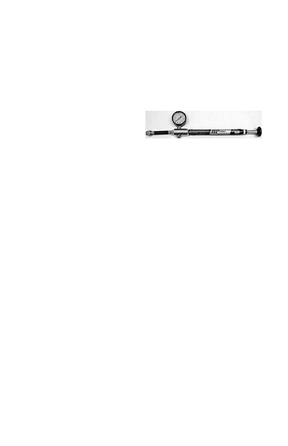
A FOX Racing Shox high pressure air pump
is available for your FLOAT shock. It is used
to add and release air pressure from your
FLOAT shock. FOX Racing Shox part num-
ber is 027-00-001-A.
Pump
8
9
To get the best performance from your FLOAT shock, it is necessary to adjust sag. On your
FLOAT shock this is done by adjusting the air pressure. The air pressure needed is determined
by the rider’s weight and riding conditions. Sag is how much the shock compresses when
you sit on the bicycle. Increasing air pressure will make the shock stiffer. Decreasing the air
pressure will make the shock softer. (Note: It might be necessary to change air pressure to
achieve the proper sag setting). The smoothest ride will be attained by running the air pres-
sure low enough to occasionally bottom out.
Note: Proper air pressure is subject to personal preferences as well. Some people prefer a
softer shock and others a firm one. During the first few rides, experiment with different pres-
sures and find the one that best suits your riding style.
Adjusting Air Pressure and Sag
FLOAT
Shock Features
Adjustable Air Spring - High Volume Air Sleeve - Internal Floating Piston - Oil Damping
Self Adjusting Air Negative Spring - Nitrogen Charged - Speed Sensitive Compression
Damping - Light-weight Chassis - Factory ProPedal
1. Locate the Schrader air valve on the shock and remove the valve cap.
2. Screw the FOX Racing Shox pump onto the air valve until the pump shows pressure on
the gauge. Do not over-tighten.
3. Add air pressure until desired pressure is shown on the gauge.
4. Unthread the pump from the air valve and measure the sag.
Repeat steps 2-4 until proper sag is achieved. Replace valve cap.
FLOAT Sag Table
Common shock lengths
Shock travel
Recommended sag
inches
millimeters
inches
millimeters
inches
millimeters
5.500
6.000
6.500
7.250
7.875
139.7
152.4
165.1
184.2
200.0
1.00
1.25
1.50
1.75
2.00
25.4
31.8
38.1
44.4
50.8
.25
.31
.38
.44
.50
6.4
7.9
9.5
11.1
12.7
FLOAT Air Spring Set-up
Follow the instructions above in the Adjusting Air Pressure and Sag Section.
FLOAT Shocks
8
9
FLOAT R
Rebound damping controls the rate at which the shock returns after it has been com-
pressed. The red adjuster dial can be turned clockwise for slower rebound and counter-
clockwise for faster rebound. There is a wide range of adjustment enabling the rider to
tune the shock to any air pressure and riding condition. The proper rebound setting is a
personal preference and varies depending on rider weight, riding style and riding condi-
tions. As a general rule, rebound should be as fast as possible without kicking back and
pushing the rider off the saddle when riding the bicycle in rough terrain. If rebound is too
slow the suspension will not function properly and the wheel will not follow the changing
terrain. Determining the proper rebound setting may take a number of rides. Use the “curb
test” to start dialing in your rebound setting. Do this test on flat ground where there is little
auto traffic and plenty of room. Ride at normal cruising speed and stay seated. Ride off a
curb and monitor the rebound. If the bike oscillates a few times after landing the rebound is
too fast. If the shock does not return promptly it is too slow. Start with the dial in the middle
(about 6 clicks from full slow) and adjust 2 clicks in the direction needed. Single clicks of
adjustment can be used to fine tune the rebound damping. During the first few rides, adjust
the rebound damping and note the different ride characteristics. Your necessary or optimum
rebound damping setting may change with different riding conditions.
Shock Features
Adjustable Air Spring - High Volume Air Sleeve - Internal Floating Piston - Oil Damping
Self Adjusting Air Negative Spring - Nitrogen Charged - Speed Sensitive Compression
Damping - Light-weight Chassis - Factory ProPedal
Externally Adjustable Rebound Damping - Speed Sensitive Rebound Valve Stack
Rebound Adjustment
FLOAT Air Spring Set-up
Follow the instructions on page 8 in the Adjusting Air Pressure and Sag Section.
��
��
��
�
��
�� � �
10
11
Please refer to Rebound Adjustment for FLOAT R.
Shock Features
Adjustable Air Spring - High Volume Air Sleeve - Internal Floating Piston - Oil Damping
Self Adjusting Air Negative Spring - Nitrogen Charged - Speed Sensitive Compression
Damping - Light-weight Chassis - 3 External Positions of ProPedal - Externally Adjustable
Rebound Damping Speed Sensitive Rebound Valve Stack - Dual Overhead Cam
Rebound Adjustment
Air Volume Adjuster - AVA
Some FLOAT shocks feature an Air Volume Adjuster or AVA. AVA technology affords a new
level of fine tuning adjustment for mountain bike rear shocks. Turning the AVA ring increas-
es or decreases the volume of the positive air spring chamber allowing the rider to alter the
shape of the spring curve. The AVA system creates a shock that, in its smallest setting, is
up to 30% more linear spring rate than a standard FLOAT shock. AVA allows as much as
200 lbs of adjustment in spring rate from fully closed to fully open when fully compressed.
AVA is a pre-ride tuning feature. The AVA system is not intended to be used on the trail or
on the fly. It is important to clean your shock, especially the threads of the AVA air sleeve
prior to adjustment. In most cases, maximum air volume will be desired. Rotation of the AVA
ring requires near complete deflation of the shock. Using a shock pump, let most or all of the
air from the shock so that the AVA ring can be easily turned. Turn the ring until it just touches
the wire ring which is snapped onto the air sleeve. This is the maximum volume setting.
Pressurize the shock and set sag as normal. AVA does not affect sag. If the shock seems to
bottom out too easily or too often, deflate the shock, rotate the ring to the next setting on the
air sleeve. Pressurize the shock, set sag and test again for full stroke performance. Repeat
this process until the setting that best fits your riding style and terrain is determined.
Air sleeve service can be performed as on other FLOAT shocks. Clean AVA seals after
every other normal FLOAT seal service, especially if riding conditions are muddy or dusty.
Carefully remove wire rings and air sleeves. Clean and inspect seals and parts for damage
or wear. Re-lubricate and carefully re-assemble. Refer to diagram for areas with critical
sealing and lubrication needs.
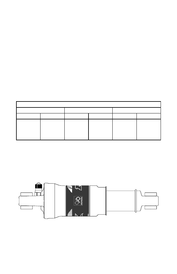
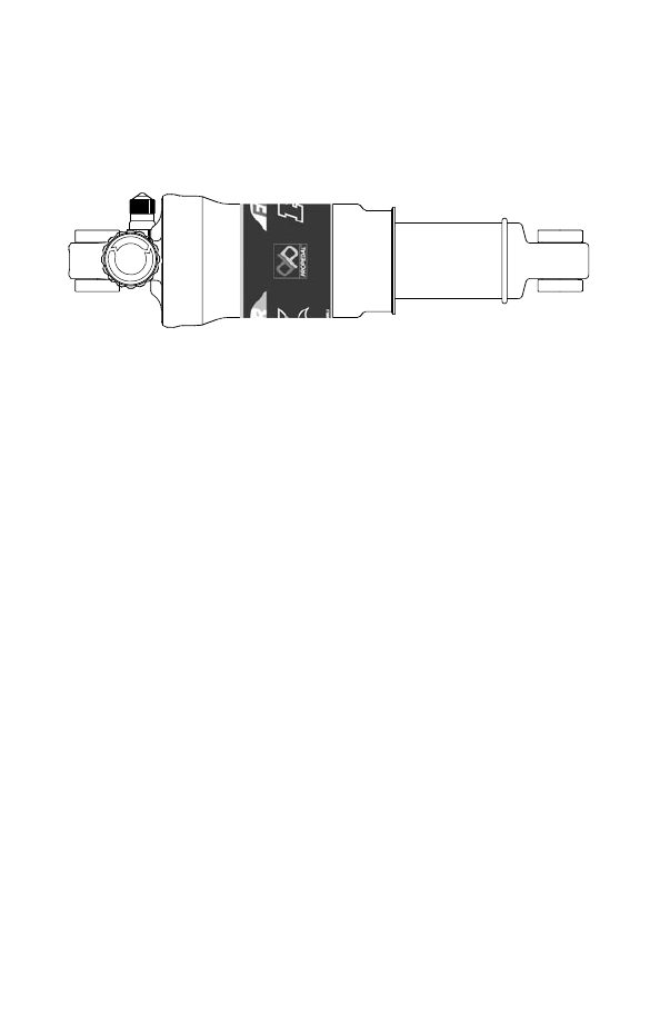
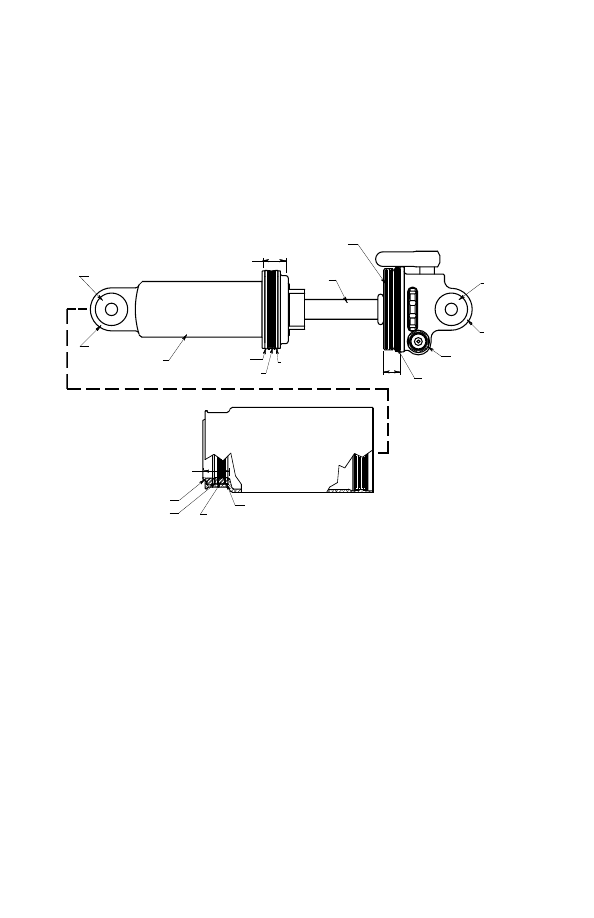
FLOAT RP3
The FLOAT RP3 features a three position ProPedal tuning lever allowing on-the-fly
ProPedal tuning. ProPedal damping reduces pedal induced suspension bob. The three
settings of the lever are full ProPedal, light ProPedal and Plush. Use the different settings
to tune the shock to different riding conditions and situations. For example, use the full
ProPedal position for riding to the top of the mountain and then switch to the Plush position
for the descent. Because suspension designs vary, some pedal inherently better than others.
To determine which ProPedal position is best, pedal the bicycle at about 15 mph and moni-
tor the shock movement. Switch between positions and select the one that reduces suspen-
sion movement most effectively while providing the desired amount of bump absorption.
The setting may change depending on conditions and riding styles.
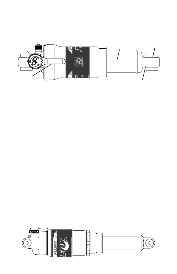
ProPedal RP3 Damping Adjustment
Rebound
Adjuster
ProPedal
RP3 Lever
'Schrader Valve
Air Sleeve
Shock Body
Eyelet
Reducer
FLOAT Air Spring Set-up
Follow the instructions on page 8 in the Adjusting Air Pressure and Sag Section.
10
11
������� ��� ��� ������
������ �������
���� ������
����� ����
�������
���� �������
���� ����
������ ���������
�����
������������
��� ������ �������
��� ������ �����
��� ������ ����
��� ������ �������
������ ��������� ����� � �����
�������
����� ������ ������
��� �����
����� ������
Release all air pressure from Air Valve.
Cycle shock a few times to release pressure from the air negative spring.
Release all air pressure from Air Valve again.
Remove shock from bike
Remove mounting hardware.
Clamp shaft eyelet in a vise with soft jaws being careful not to crush the air valve, RP3 lever,
or rebound knob.
Slide a screwdriver or punch through the body eyelet to keep the air sleeve from coming off
the body.
Loosen air sleeve by turning counter clockwise and slide it down the body.
Remove screwdriver or punch and remove air sleeve from shock.
Air Sleeve Maintenance
See www.foxracingshox.com for downloadable video instructions.
Greasing and Reassembling
Lightly lube the shaft eyelet O-ring and shaft eyelet threads with FLOAT Fluid or
Multi-purpose
Lithium based grease (NLGI #2).
Liberally lube the body seal and body bearing, leaving a reservoir of lube above the body bearing .
Lightly grease the air sleeve seal, air sleeve bearing, and air sleeve wiper. Use Slick Honey
on this part of the shock for best results.
Slide the air sleeve over the body until the air sleeve wiper is at the end of the body. Leave
the air sleeve unthreaded at this time.
(The air sleeve will be very difficult to compress because there is pressure trapped in the
air negative chamber. Waiting until after the shock is mounted in the bike will allow the
leverage of the bike to easily compress the shock.)
Dry bushings and reducers.
Install reducers in eyelet bushings and install shock in bike.
Carefully compress shock until you can screw on the air sleeve. Don't let the air sleeve slip
off the body.
Thread air sleeve onto shaft eyelet hand tight.
Inflate shock using inflation instructions listed in the Pump Instructions.
Clean inside of the air sleeve with parts cleaner. Inspect the seal and bearing inside of the
air sleeve. Replace if damaged or worn.
Clean body, body seal, body bearings and shaft with parts cleaner.
Inspect body seal and body bearings for wear or damage. Replace if damaged or worn.
Cleaning and Inspecting
Note: If needed, the Air Sleeve Seal Kit part number is 803-00-050-B.
FLOAT Fluid part numbers: 025-03-002-A 5 cc Pillow Pack
025-03-003-A 8 oz. Bottle
12
13
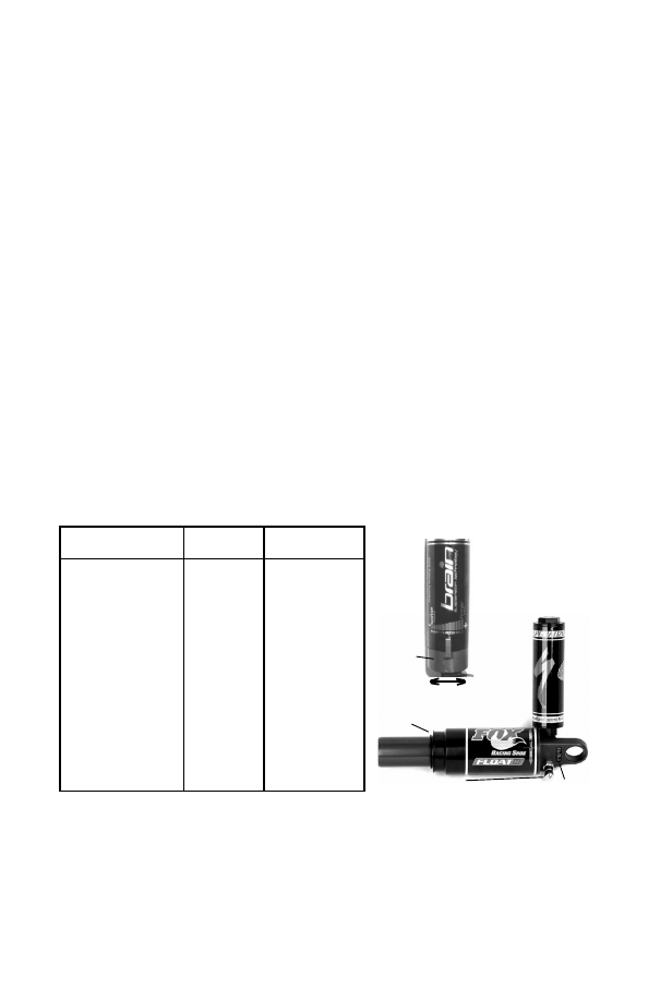
Specialized Bicycles with Brain and Brain Adjust Technology
Brain technology senses bumps in the trail and activates the suspension giving the rider the
efficiency of a hardtail with all the benefits of a full suspension bicycle.
To optimize the performance of the shock, it is important to set it up correctly. Taking the
time to tune the spring rate (air pressure) and rebound damping (rate at which the shock
returns) will greatly enhance the riding experience.
The method for setting sag on a Brain-equipped bicycle is slightly different than that used
for traditional shocks.
1. Begin by sliding the travel indicator o-ring to the scraper lip.
2. Sit on the bicycle in a normal riding position. It is best to wear normal riding gear during
this step. Remain steady and still in this position for ten (10) seconds. This will allow the
shock to “sit” into its travel.
3. Dismount the bicycle and measure between the scraper lip and the travel indicator o-ring.
4. Recommended sag is 10mm. Adjust air pressure in 5psi increments until sag is achieved.
An alternative to setting sag is to set the air pressure according to the air spring chart below.
1. Find the rider’s weight in the left column and set air pressure per the middle column.
2. Set the rebound dial per the column on the right of the air spring chart.
Air sleeve service can be performed as on other FLOAT rear shocks (see pages 10&11).
The strut must be removed before removing the air sleeve. A 22mm open end wrench is
required to remove the strut. Torque to 175-200 in-lb (19.5-22.5 N-m) when reinstalling. A
22mm crowfoot torque wrench is required to install the strut.
Bump Threshold Adjustment
Some Brain-equipped shocks feature a bump threshold adjustment. This changes the
Brain’s sensitivity to bumps allowing a firmer (race) or softer (comfy) ride.
1. Rotate the blue lever at the base of the Brain towards the left chainstay to increase the
bump threshold. This will make the Brain less sensitive thus requiring a larger bump to activate.
2. Rotate the blue lever away from the left chainstay to decrease the bump threshold. This
will increase the sensitivity of the Brain. Smaller bumps will now activate the suspension.
Note: Most repairs and warranty issues related to the FOX FLOAT R shock with Brain
Technology must be performed through an Authorized Specialized Dealer in your coun-
try. Please contact your Specialized Dealer for service, repair or warranty issues. Some
FOX Racing Shox Service Centers can service and repair Brain shocks. Please see
www.foxracingshox.com for Service Center updates.
Setting Rebound
Rebound damping controls the rate at which the shock returns after it has compressed. The
red adjuster dial is used to speed up or slow down the rebound damping.
1. Turn the Rebound Adjuster Dial clockwise until it stops.
2. Consult the air pressure chart below and find the rider’s weight in the left column. Read
across to the column on the right and find the corresponding number of clicks and set the
Rebound Adjuster Dial by turning the dial counter-clockwise and counting the number of clicks.
Schrader Valve
Rebound Adjuster Dial
Travel Indicator O-ring
Less
sensitive
Blue
Lever
More
sensitive
Rider weight
Pounds (Kilograms)
Air pressure
PSI
Rebound clicks
from closed
90-100 (41-45)
100-110 (45-50)
110-120 (50-54)
120-130 (54-60)
130-140 (60-64)
140-150 (64-68)
150-160 (68-73)
160-170 (73-77)
170-180 (77-82)
180-190 (82-86)
190-200 (86-91)
200-210 (91-95)
210-220 (95-100)
220-230 (100-104)
230-240 (104-109)
240-250 (109-113)
250-265 (113-120)
265-280 (120-127)
280-295 (127-134)
60-62
62-65
65-68
68-71
71-74
74-79
79-84
84-89
89-94
94-99
99-104
104-114
114-124
124-134
134-144
144-154
154-169
169-184
184-199
21-20
21-20
20-18
20-18
18-16
18-16
18-16
16-14
16-14
16-14
14-12
14-12
14-12
12-10
12-10
10-8
10-8
8-6
6-4
12
13
The K2 Razorback is equipped with a FOX Racing Shox FLOAT RL Pull Shock. To get the
best performance from your K2 Razorback, it is necessary to adjust the suspension. The first
step is to adjust the air pressure using the Schrader valve on the shock. The proper air
pressure is a personal preference and varies upon your weight and riding style. During the
first few rides adjust the air pressure to find your personal preference. Set air pressure (psi)
equal to your body weight as a starting point. If necessary, adjust in 5psi increments to suit
your personal preference.
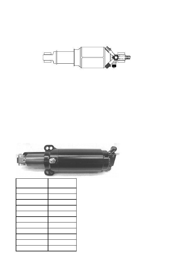
Compression Enhancement
Razorbacks come with a shock with compression
enhancement. The purpose of the compression
enhancement is to limit suspension movement
when desired by the rider. It is adjusted with the
blue lever at the end of the shock. The shock can
be oriented two ways on the bike. If the lever is
located on the right side of the shock and bike
(from the rider's perspective) rotate the lever until
it is pointing up and back for normal compression
damping. From that position, rotate the lever 90º
until it points down and back for compression
enhancement. If the lever is on the bottom of the
shock, when it points left and back there will be
extra compression damping limiting suspension
movement. Rotate the lever 90º until it points
right and back for normal compression damping.
Rebound Adjustment
K2 Razorbacks have a shock with rebound adjustment. Rebound damping is adjusted by
the red rebound wheel. Rebound damping controls the speed at which the shock returns to
its original position after the shock is compressed. The shock has 12 clicks of adjustment
from fully closed. Turning the knob clockwise will cause the rebound to be slower.
The proper rebound setting is a personal preference and varies upon your weight and riding style.
Experts agree that rebound should be as fast as possible without kicking back and pushing
the rider off the saddle when riding the bike in rough terrain. If rebound is set too slow, the
suspension will not have the time to extend before hitting the next bump
K2 Razorback Pull Shock
Rider weight
Pounds (kilograms)
Air pressure
(psi)
90-100 (41-45)
90-100
100-110 (45-50)
100-110
110-120 (50-54)
110-120
120-130 (54-60)
120-130
130-140 (60-64)
130-140
140-150 (64-68)
140-150
150-160 (68-73)
150-160
160-170 (73-77)
160-170
170-180 (77-82)
170-180
180-190 (82-86)
180-190
190-200 (86-91)
190-200
Specialized Bicycles with Triad Shocks
Some Specialized bicycles feature a FOX Racing Shox Triad shock. The Triad has three on-
the-fly suspension adjustment settings - 1)Fully locked out 2) ProPedal for a more efficient ride
and 3) Fully open and plush. Generally, the locked out position is used for climbing and road
riding, the ProPedal position is used for pedalling sections where a combination of compliance
and efficiency is still needed and the fully open and plush position is used for descending.
Note: When the red
rebound wheel is
advanced to positions
towards full in, or full
clock-wise, the blue
lock-out lever will feel
slack. This is normal.
Open
Locked
Pedal
14
15
Vanilla Shocks
To get the best performance from your Vanilla shock, it is necessary to adjust sag. On the
coil-over shocks this is done by adjusting the spring preload or changing springs. Sag is how
much the shock compresses when you sit on the bicycle. Increasing spring preload will make
the shock compress less. Decreasing the preload will make the shock compress more. The
smoothest ride will be achieved with one turn of preload. (Note: it might be necessary to change
spring rate to achieve the proper sag setting.) Adjusting sag setting is easiest with two people,
the bike rider and an assistant. See page 6 for Sag Measurement instructions.
If more than 2 turns of preload are required
to achieve the correct amount of sag, it
is recommended that a higher rate spring
be installed.
Vanilla & DHX Sag Table
Shock travel
Recommended sag
Inches (Millimeters)
Inches (Millimeters)
1.00 (25.4)
1.25 (31.7)
1.50 (38.1)
1.75 (44.4)
2.00 (50.8)
2.25 (57.1)
2.50 (63.5)
2.75 (69.9)
3.00 (76.2)
.25 (6.4)
.31 (7.9)
.38 (9.5)
.44 (11.1)
.50 (12.7)
.56 (14.3)
.63 (15.9)
.69 (17.5)
.76 (19.0)
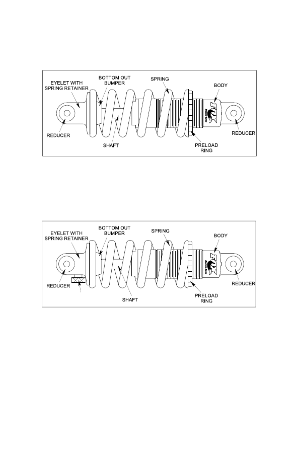
������� ����
������� ���� �����
����������� �����
�������
�������
�
�
�
�
�
�
������
����
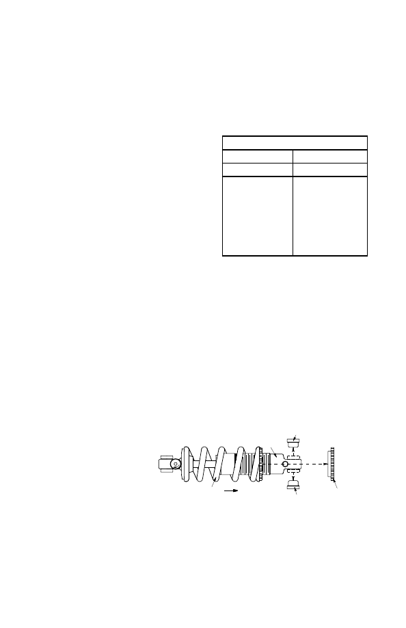
Loosen and remove the preload
ring from the body. Note: It might
be necessary to remove the
reducers from the body end of
the shock to remove the spring.
Slide the spring over the shock
body. Install your new spring
by sliding the spring over the
shock body. Tighten the preload
adjuster one full turn to keep the
preload ring from shaking loose.
Installing and Removing Springs
Vanilla & Vanilla R
To set preload it is necessary to adjust the spring preload ring. FOX Racing Shox recom-
mends no more than two (2) turns of preload. Increase preload by turning the ring clock-
wise. Decrease preload by turning the ring counter-clockwise. Make sure the preload ring
is always in contact with the spring. If desired preload cannot be achieved with the preload
ring, change the spring. (See Installing and Removing Springs) A stiffer spring (higher
spring rate) decreases sag and a softer spring (lower spring rate) increases sag. Springs
are available from FOX Racing Shox (800-FOX-SHOX) and authorized dealers and Service
Centers. Numbers are printed on the outside of the spring coils indicating the rate (in
pounds) and travel (in inches) Example: 550-1.95 is a 550 pound-per-inch spring rate with
1.95 inches of travel. Please note this number when ordering springs. Also be prepared
with the make, model and year of the bicycle plus shock travel, rider weight and riding style.
14
15
Vanilla
Shock Features
Adjustable Spring Preload - External Coil Spring - Internal Floating Piston - Oil Damping
One Piece Aluminum Body - One Piece Eyelet - Nitrogen Charged
Speed Sensitive Compression Damping
Shock Features
Adjustable Spring Preload - External Coil Spring - Internal Floating Piston - Oil Damping
One Piece Aluminum Body - One Piece Eyelet - Nitrogen Charged
Speed Sensitive Compression Damping - Factory Tuned ProPedal - Multi-Valve Piston
12 Click Externally Adjustable Rebound Damping - Speed Sensitive Rebound Valve Stack
Vanilla R
Rebound Adjustment
Rebound damping controls the rate at which the shock returns after it has been com-
pressed. The red adjuster dial can be turned clockwise for slower rebound and counter-
clockwise for faster rebound. There is a wide range of adjustment enabling the rider to tune
the shock to any air pressure and riding condition. The proper rebound setting is a personal
preference and varies depending on rider weight, riding style and riding conditions. As
a general rule, rebound should be as fast as possible without kicking back and pushing
the rider off the saddle when riding the bicycle in rough terrain. If rebound is too slow the
suspension will not function properly and the wheel will not follow the changing terrain.
Determining the proper rebound setting may take a number of rides. Use the “curb test” to
start dialing in your rebound setting. Do this test on flat ground where there is little auto traf-
fic and plenty of room. Ride at normal cruising speed and stay seated. Ride off a curb and
monitor the rebound. If the bike oscillates a few times after landing the rebound is too fast.
If the shock does not return promptly it is too slow. Start with the dial in the middle (about
7 clicks from full slow) and adjust 2 clicks in the direction needed. Single clicks of adjust-
ment can be used to fine tune the rebound damping. During the first few rides, adjust the
rebound damping and note the different ride characteristics. Your rebound damping setting
may change with different riding conditions.
REBOUND ADJUSTER
KNOB (RED)
16
17
Rebound Adjustment
Please refer to Rebound Adjustment for the Vanilla R on Page 15.
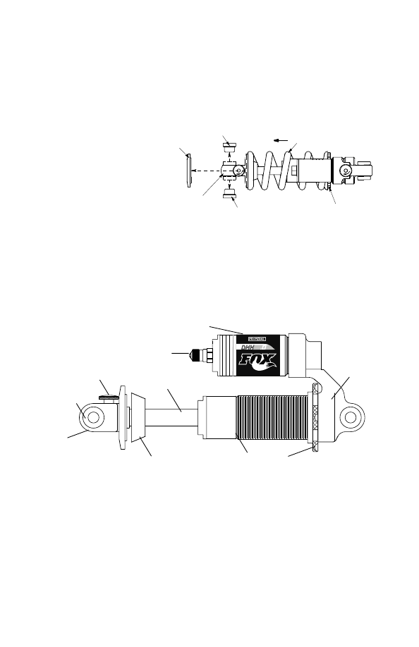
DHX 3.0
Shock Features
Adjustable Spring Preload - External Coil Spring - Internal Floating Piston - Oil Damping
Nitrogen Charged - Speed Sensitive Shim Controlled Compression Damping
12 Click Externally Adjustable Velocity Sensitive Rebound Damping - Speed Sensitive
Rebound Valve Stack - Boost Valve Position Sensitive Adjustment - Factory Tuned ProPedal
�
Slotted
Spring
Retainer
Preload Ring
Rebound Adjuster Knob
Eyelet
Reducer
Shaft
Bottom
Out Bumper
Reservoir
Schrader
Valve
Body
Body Cap
Boost Valve Adjustment
The Boost Valve controls the shock's compression damping. On the 3.0 model you can
alter the pedaling efficiency and bottoming resistance of the shock via the Schrader valve.
The pressure range of the Boost Valve is 75-200psi and is factory set at 150psi which
should be a good starting point for most riders. Ride the bicycle on rough terrain and note
the compression characteristics of the shock. If it seems that the ride is too firm and there
is too much compression damping, attach a shock pump to the schrader valve and reduce
the air pressure 10-15psi. Repeat this procedure until desired compression damping is
achieved. If compression damping is too light, add 10-15psi until desired compression
damping is achieved. Use care when attaching and removing the pump not to lose too
much air pressure. The Boost Valve uses high pressures in a small volume so small pres-
sure losses can affect performance.
Important Note: DO NOT ride or cycle the DHX shock
with less than 75 psi in the Boost Valve. This will damage the shock requiring repairs that
are NOT covered under warranty.
Installing DHX Shocks
If installing a DHX shock on a bicycle that was not originally supplied with a DHX shock, it
is very important to install the shock without the spring and carefully cycle the suspension
through its travel. Check that all parts of the shock are clear of the frame and swingarm
through the full travel of the suspension.
Setting Sag on DHX Shocks
Set sag on DHX shocks the same as Vanilla shocks. See instructions and Sag table on page 14.
Sag on DHX shocks can be as much as 33% of shock travel.
DHX
�������
����� ������
������� �� ������ �������
������� ����
�������
�������
��������
�
�
�
�
�
�
��
�
�
�
�
��������
������ ���� ����� �������
�������
Back off preload ring to loosen
the spring until the slotted spring
retainer can be removed from the
shock. Note: It might be neces-
sary to remove the reducers
from the shaft end of the shock
to remove the spring. Slide the
spring over the eyelet. Slide the
new spring on over the eyelet,
and re-install the spring retainer. Note: The slotted spring ring retainer slot must rest on
the flat side of the spring. If the slot is straddling the gap caused by the end of the spring
wire the slotted spring retainer may bend. Tighten the preload adjuster one full turn to keep
the spring retainer from shaking loose. Align the slotted spring retainer so that the rebound
knob is in the middle of the slot.
Changing Springs
16
17
Rebound Adjustment
Please refer to Rebound Adjustment for the Vanilla R on Page 15.
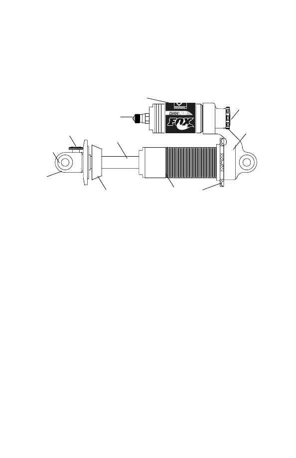
DHX 4.0
Slotted
Spring
Retainer
Preload Ring
Rebound Adjuster Knob
Eyelet
Reducer
Shaft
Bottom
Out Bumper
Reservoir
Schrader
Valve
Body
Body Cap
ProPedal
Adjustment
Knob
Installing DHX Shocks
Please see the note about DHX Shock installation on Page 17.
Boost Valve Adjustment
Please refer to Boost Valve Adjustment for the DHX 3.0 on Page 17.
ProPedal Adjustment
The ProPedal Adjustment knob allows the rider to adjust the amount of ProPedal damping.
ProPedal damping affects the first part of the compression stroke and is designed to control
pedal induced suspension bob. Since suspension designs vary not all bicycles require the
same degree of ProPedal damping. There are 15 clicks of adjustment. Rotate the knob all
the way counter-clockwise for the lightest ProPedal setting and all the way clockwise for the
most ProPedal damping.
ProPedal and Boost Valve Interaction
While they are separate adjustments, aspects of the Boost Valve can influence the
ProPedal adjustment. If the ProPedal Adjustment Knob is all the way counter-clockwise
in the lightest ProPedal damping position and the compression damping is still to strong,
attach a shock pump to the schrader valve on the Boost Valve and reduce the pressure
10-15psi. Repeat these steps to achieve the desired compression damping. If there is not
enough compression damping with the ProPedal knob fully clockwise, add 10-15psi to the
Boost Valve until desired compression damping is achieved.
Shock Features
Adjustable Spring Preload - External Coil Spring - Internal Floating Piston - Oil Damping
Nitrogen Charged - Speed Sensitive Shim Controlled Compression Damping
12 Click Externally Adjustable Velocity Sensitive Rebound Damping - Speed Sensitive
Rebound Valve Stack - Boost Valve Position Sensitive Adjustment - ProPedal Adjustment
Setting Sag on DHX Shocks
Set sag on DHX shocks the same as Vanilla shocks. See instructions and Sag table on page 14.
Sag on DHX shocks can be as much as 33% of shock travel.
18
605-00-038 2004 FOX Racing Shox. 2005 Rear Shock Owner's Manual. The information herein is provided as a guide.
FOX Racing Shox reserves the right to change all or part without notice.
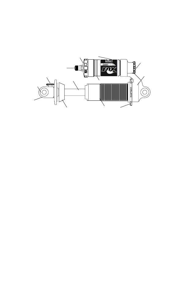
DHX 5.0
Bottom-out Adjustment
The blue knob on the end of the reservoir is used to adjust bottom-out resistance and
affects the last part of the compression stroke. Bottom-out should be adjusted with a maxi-
mum of 125psi in the Boost Valve. The knob can be turned by hand or with a 4mm hex key
inserted into one of the holes around the perimeter.
Do not use any other tool to turn the
knob - 4mm hex key only! Turn the knob all the way clockwise for the most bottom-out
resistance and counter-clockwise for the least. There are three (3) rotations of adjustment
and three (3) corresponding Adjustment Indicator Lines on the reservoir.
Note: If the knob feels gritty during rotation, set the knob to maximum volume and then
use a 2mm (8-32) hex key to loosen the set screws in the perimeter holes and remove the
knob. Clean thoroughly, grease and re-install.
Slotted
Spring
Retainer
Preload Ring
Rebound Adjuster Knob
Eyelet
Reducer
Shaft
Bottom
Out Bumper
Reservoir
Schrader
Valve
Body
Body Cap
ProPedal
Adjustment
Knob
Bottom-out
Adjustment
Knob
Adjustment Indicator Lines
Installing DHX Shocks
Please see DHX Shock installation instructions for the DHX 3.0.
Boost Valve Adjustment
Please refer to Boost Valve Adjustment for the DHX 3.0.
ProPedal Adjustment
Please refer to ProPedal Adjustment for the DHX 4.0.
ProPedal and Boost Valve Interaction
Please refer to ProPedal and Boost Valve Interaction for the DHX 4.0.
Shock Features
Adjustable Spring Preload - External Coil Spring - Internal Floating Piston - Oil Damping
Nitrogen Charged - Speed Sensitive Shim Controlled Compression Damping
12 Click Externally Adjustable Velocity Sensitive Rebound Damping - Speed Sensitive
Rebound Valve Stack - Boost Valve Position Sensitive Adjustment - ProPedal Adjustment
Bottom-out Adjustment
Rebound Adjustment
Please refer to Rebound Adjustment for the Vanilla R on Page 15.
Setting Sag on DHX Shocks
Set sag on DHX shocks the same as Vanilla shocks. See instructions and Sag table on page 14.
Sag on DHX shocks can be as much as 33% of shock travel.
Wyszukiwarka
Podobne podstrony:
fiat multipla Instrukcja obsługi 60360942 06 2005
instrukcja obsługi lancia lybra pl 11 2005 (2)
Instrukcja obsługi Radia samochodowego z Opla marki CDR 2005 SIEMENS VDO J ANG
Piec LSL UB Instrukcja obsługi
Instrukcja obslugi Uchwyt samoc Nieznany
INSTRUKCJA OBSŁUGI DEKODER SAGEM ISD 4285 PL
Instrukcja obsługi interfejs KKL OPEL, BMW, VAG
Instrukcja obsługi Farymann 15D 18D
Instrukcja obslugi wymiennikow CB alfa laval
Instrukcja obslugi klimatyzacji Vectra B
14 Instrukcja obsługi BFZ
INSTRUKCJA OBSŁUGI APARAT KODAK EASYSHARE Z1285 PL
iobsł Dłutownica DAA-16, BHP, Instrukcje-Obsługi
INSTRUKCJA OBSŁUGI HYDRAULICZNEJ NADZIEWARKI DO KIEŁBAS(1), GOTOWANIE I ŻYWIENIE, GASTRONOMIA
pHmetr-instrukcja obsługi, Inżynieria środowiska, inż, Semestr II, Chemia ogólna, laboratorium
Czyszczarka naroża CNR-200, BHP, Instrukcje-Obsługi
więcej podobnych podstron