
B R A K E
S Y S T E M
Return To Main Table of Contents
GENERAL . . . . . . . . . . . . . . . . . . . . . . . . . . . . . . . . . . . . . . . . . . . . . .
BRAKE PEDAL . . . . . . . . . . . . . . . . . . . . . . . . . . . . . . . . . . . . . . . . 1 0
MASTER CYLINDER . . . . . . . . . . . . . . . . . . . . . . . . . . . . . . . . . . 13
BRAKE BOOSTER . . . . . . . . . . . . . . . . . . . . . . . . . . . . . . . . . . . . . 16
BRAKE LINE . . . . . . . . . . . . . . . . . . . . . . . . . . . . . . . . . . . . . . . . . . 18
PROPORTIONING VALVE . . . . . . . . . . . . . . . . . . . . . . . . . . . . . 19
FRONT DISC BRAKE . . . . . . . . . . . . . . . . . . . . . . . . . . . . . . . . . 20
REAR DRUM BRAKE (BENDIX). . . . . . . . . . . . . . . . . . . . . . .
REAR DRUM BRAKE (MANDO) . . . . . . . . . . . . . . . . . . . . . .
PARKING BRAKE . . . . . . . . . . . . . . . . . . . . . . . . . . . . . . . . . . . . . 33

GENERAL
GENERAL
GENERAL SPECIFICATIONS
Master cylinder
Type
I.D.
Fluid level warning sensor
Brake booster
Type
Effective dia.
Boosting ratio
Proportioning valve
Cut-in pressure (Split point)
Decompression ratio
Front brake
Type
Disc O.D.
Disc thickness
Pad thickness
Cylinder I.D.
Rear brake
Type
Drum I.D.
Brake lining thickness
Cylinder I.D.
Clearance adjustment
Parking brake
Type
Braking type
Cable arrangement
Tandem
22.22 mm (0.875 in.)
Provided
Vacuum
233.1 mm (9.177 in.)
4.0 : 1
3.63 MPa (37 kg/cm
2
, 526 psi)
3.7 : 1
Floating type with ventilated disc
242 mm (9.53 in.)
19 mm (0.75 in.)
9 mm (0.354 in.)
54 mm (2.126 in.)
BENDIX
MANDO
Leading-trailing drum
180 mm (7.1 in.)
4.85 mm (0.19 in.)
Leading: 4.5 mm (0.177 in.)
Trailing: 4.6 mm (0.181 in.)
20.64 mm (0.813 in.)
20.62 mm (0.812 mm)
Automatic
Mechanical brake acting on rear wheels
Lever type (cam shape)
V type
5 8 - 2

GENERAL
SERVICE STANDARD
Standard value
Brake pedal height
Brake pedal stroke
Stop light switch outer case to pedal arm clearance
Brake pedal free play
Brake pedal to floorboard clearance
Booster push rod to master cylinder piston clearance
Parking brake lever stroke (when lever assembly is
pulled with 196 N (20 Kg, 44 lb) force)
Service limit
Front disc brake pad thickness
Front disc thickness (minimum)
Front disc runout
Drum brake lining thickness
Brake drum I.D. (maximum)
Wheel cylinder to piston clearance
163-168 mm (6.417-6.614 in.)
143 mm (5.63 in.)
0.5-1.0 mm (0.020-0.040 in.)
10-15 mm (0.394-0.591 in.)
50 mm (1.969 in.) or more
0 (at 500 mmHg vacuum)
6-7 clicks
1.0 mm (0.039 in.)
17 mm (0.669 in.)
0.15 mm (0.006 in.)
1.0 mm (0.039 in.)
182 mm (7.165 in.)
0.15 mm (0.006 in.)
TIGHTENING TORQUE
Nm
kg.cm
lb.ft
Master cylinder to booster mounting nut
Brake booster mounting nut
Brake booster hose fitting to manifold
Bleeder screw
Brake tube flare nut, brake hose
Proportioning valve mounting nut
Caliper guide rod bolt
Caliper pin bolt
Caliper assembly to knuckle
Brake hose to front caliper
Backing plate mounting bolt
Wheel cylinder mounting bolt
8 - 1 2
8 0 - 1 2 0
8 - 1 2
8 0 - 1 2 0
8 - 1 2
8 0 - 1 2 0
7 - 9
7 0 - 9 0
1 3 - 1 7
1 3 0 - 1 7 0
8 - 1 2
8 0 - 1 2 0
2 2 - 3 1
2 2 0 - 3 2 0
3 4 - 4 4
3 5 0 - 4 5 0
6 4 - 7 4
6 5 0 - 7 5 0
2 5 - 3 0
2 5 0 - 3 0 0
4 9 - 5 9
5 0 0 - 6 0 0
1 2 - 1 8
1 2 0 - 1 8 0
5 . 8 - 8 . 7
5 . 8 - 8 . 7
5 . 8 - 8 . 7
5 . 1 - 6 . 5
9 - 1 2
5 . 8 - 8 . 7
1 6 - 2 3
2 5 - 3 2
4 7 - 5 4
1 8 - 2 2
3 6 - 4 3
8 . 7 - 1 3
5 8 - 3
GENERAL
SPECIAL TOOL
Tool
(Number and name)
Illustration
U s e
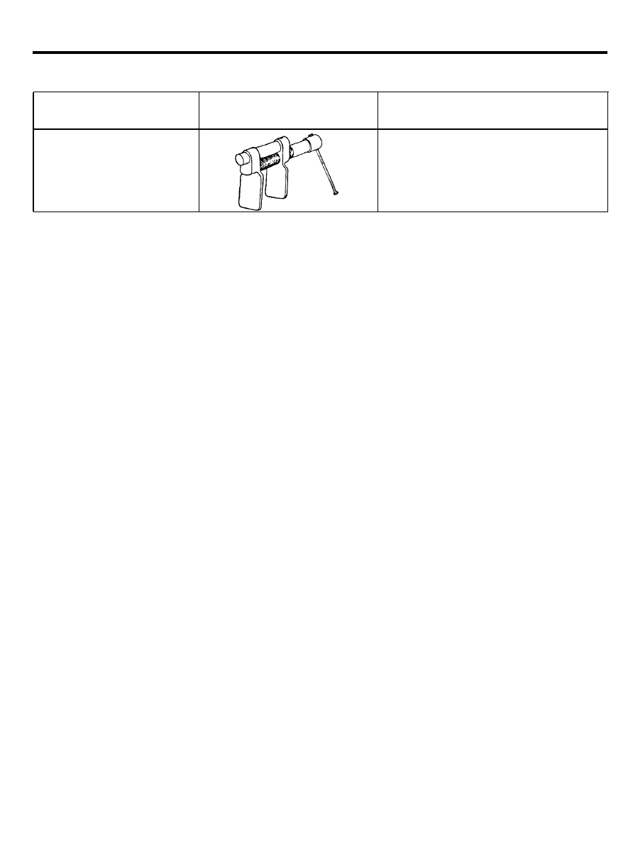
0 9 5 8 1 - 1 1 0 0 0
Piston expander
Retraction of the front disc brake piston
5 8 - 4

TROUBLESHOOTING
Symptom
Noise or vibration when
brakes are applied
Vehicle pulls to one side
when brakes are applied
Insufficient braking power
Increased pedal stroke
(Reduced pedal to floorboard
clearance)
Probable cause
Remedy
Backing plate or caliper improperly mounted
Correct
Loose backing plate or caliper mounting bolts
Retighten
Unevenly worn or cracked brake drum or brake disc
Replace
Foreign material in brake drum
Clean
Seized pad or lining contact surface
Replace
Excessive caliper to pad assembly clearance
Correct
Uneven pad contact
Correct
Lack of lubrication in sliding parts
Lubricate
Loose suspension parts
Retighten
Difference in left and right tire inflation pressure
Adjust
Improper front wheel alignment
Adjust
Inadequate contact of pad or lining
Correct
Grease or oil on pad or lining surface
Replace
Drum eccentricity or uneven wear
Replace
Incorrect wheel cylinder installation
Correct
Auto adjuster malfunction
Correct
Low or contaminated brake fluid
Replenish or change
Air in brake system
Bleed the system
Brake booster malfunction
Correct
Inadequate contact of pad or lining
Correct
Grease or oil on pad surface
Replace
Auto adjuster malfunction
Correct
Overheated brake rotor due to dragging of pad
Correct
or lining
Restricted brake line
Correct
Proportioning valve malfunction
Replace
Air in brake system
Bleed the system
Brake fluid leaks
Correct
Auto adjuster malfunction
Correct
Excessive push rod to master cylinder clearance
Adjust
5 8 - 5

Symptom
Brake drag
Insufficient parking
brake function
Probable cause
Remedy
Incomplete release of parking brake
Incorrect parking brake adjustment
Weak brake pedal return spring
Restricted master cylinder return port
Broken rear drum brake shoe return spring
Lack of lubrication in sliding parts
Defective master cylinder check valve or
piston return spring
Correct
Adjust
Replace
Correct
Replace
Lubricate
Replace
Insufficient push rod to master cylinder clearance
Worn brake lining
Grease or oil on lining surface
Parking brake cable sticking
Auto adjuster malfunction
Excessive parking brake lever stroke
Adjust
Replace
Replace
Replace
Correct
Adjust the parking
brake lever stroke or
check the parking
brake cable routing
5 8 - 6
SERVICE ADJUSTMENT PROCEDURE
BRAKE PEDAL INSPECTION AND ADJUSTMENT
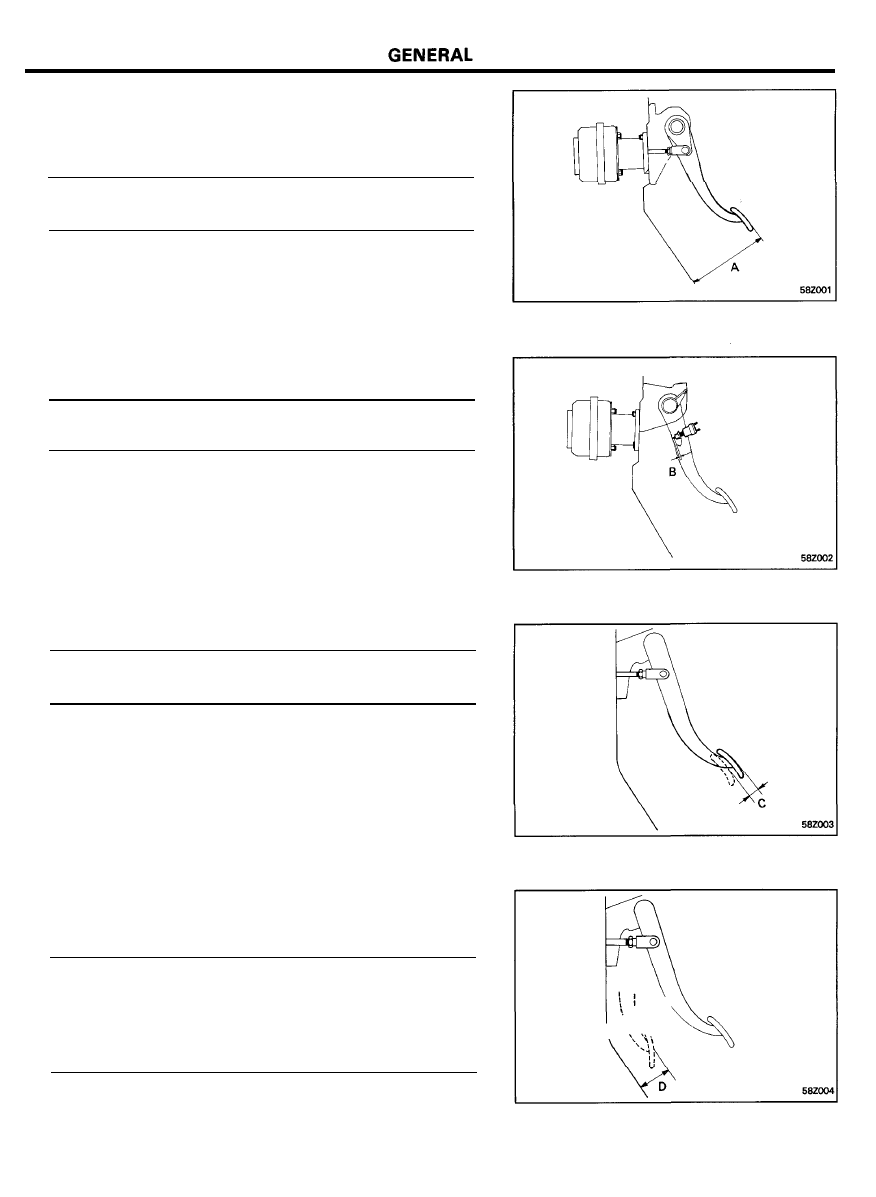
1. Pedal height
Pedal height (from top of pedal to toeboard) A . . . . . . . . . .
163-168 mm (6.417-6.614 in.)
If the pedal height is out of specification, adjust by the
following procedure.
1) Back off the stop lamp switch to a position where it does
not contact the pedal arm.
2) Turn the stop lamp switch until the clearance between
the stop lamp switch outer case and the pedal arm is
within the standard value, and tighten the lock nut.
Clearance between pedal and stop lamp switch B . . . . . . .
0.5 to 1.0 mm (0.02 to 0.039 in.)
2. Brake pedal free play.
Brake pedal free play C. . . . . . . . . . . . . . . . . . . . . . .
10-15 mm (0.394-0.591 in.)
3. Start the engine, apply the brake pedal with approximately
50 kg (110 lbs.) of force, and measure the clearance between
the brake pedal and the floor board.
Pedal to floor board clearance D
when pedal is depressed 50 kg (110 lbs.) force . . . . . . .
70 mm (2.76 in.) or more
when pedal is fully depressed without brake fluid . . . . .
50 mm (1.97 in.) or more
5 8 - 7
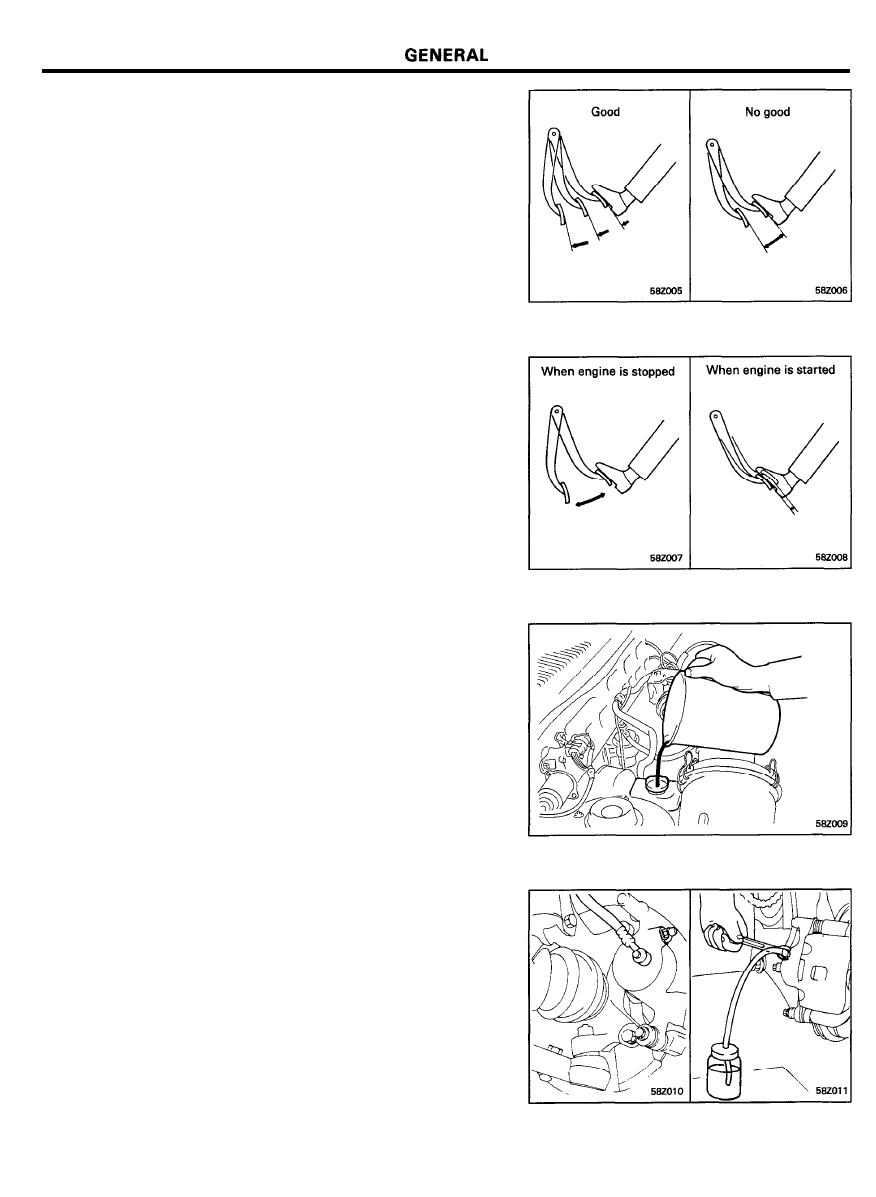
BRAKE BOOSTER OPERATION TEST WITHOUT
A TESTER
For a simple check of the brake booster operation, make the
following tests.
1. Run the engine for one or two minutes, then stop it. Depress
the brake pedal several times using normal foot pressure. If
the pedal goes down further the first time, but gradually rises
after the second or third time, the brake booster is
functioning properly. Go to step 2.
2. With the engine stopped, depress the brake pedal several
times.
Depress the brake pedal and start the engine.
If the pedal goes down slightly, the booster is in good
condition. Go to step 3.
3. With the engine running, depress the brake pedal and then
stop the engine.
Hold the pedal depressed for 30 seconds. If the pedal height
does not change, the booster is in good condition.
If one of the above three tests is not okay, check the vacuum
hoses, the check valve and the brake booster. Make any
necessary corrections. If all the tests are OK, unit is good.
BLEEDING OF BRAKE SYSTEM
1. Remove the reservoir cap and fill the brake fluid reservoir.
CAUTION
Do not allow brake fluid to remain on a painted surface.
Wash it off immediately.
NOTE
When pressure bleeding the system, do not depress the
brake pedal.
2. Connect a vinyl tube to the wheel cylinder bleeder screw and
insert the other end of tube in a half full container of brake
fluid.
3. Slowly pump the brake pedal several times.
4. While depressing the brake pedal fully, loosen the bleeder
screw until fluid starts to run out. Then close the bleeder
screw.
5 8 - 8
GENERAL
5. Repeat steps 3 and 4 until there are no more bubbles in the
fluid.
6. Tighten the bleeder plug screw.
Bleeder screw tightening torque . . . . . . . . . . . . . . . . . . . . . . . .
7-9 Nm (70-90 kg.cm, 5.1-6.5 lb.ft)
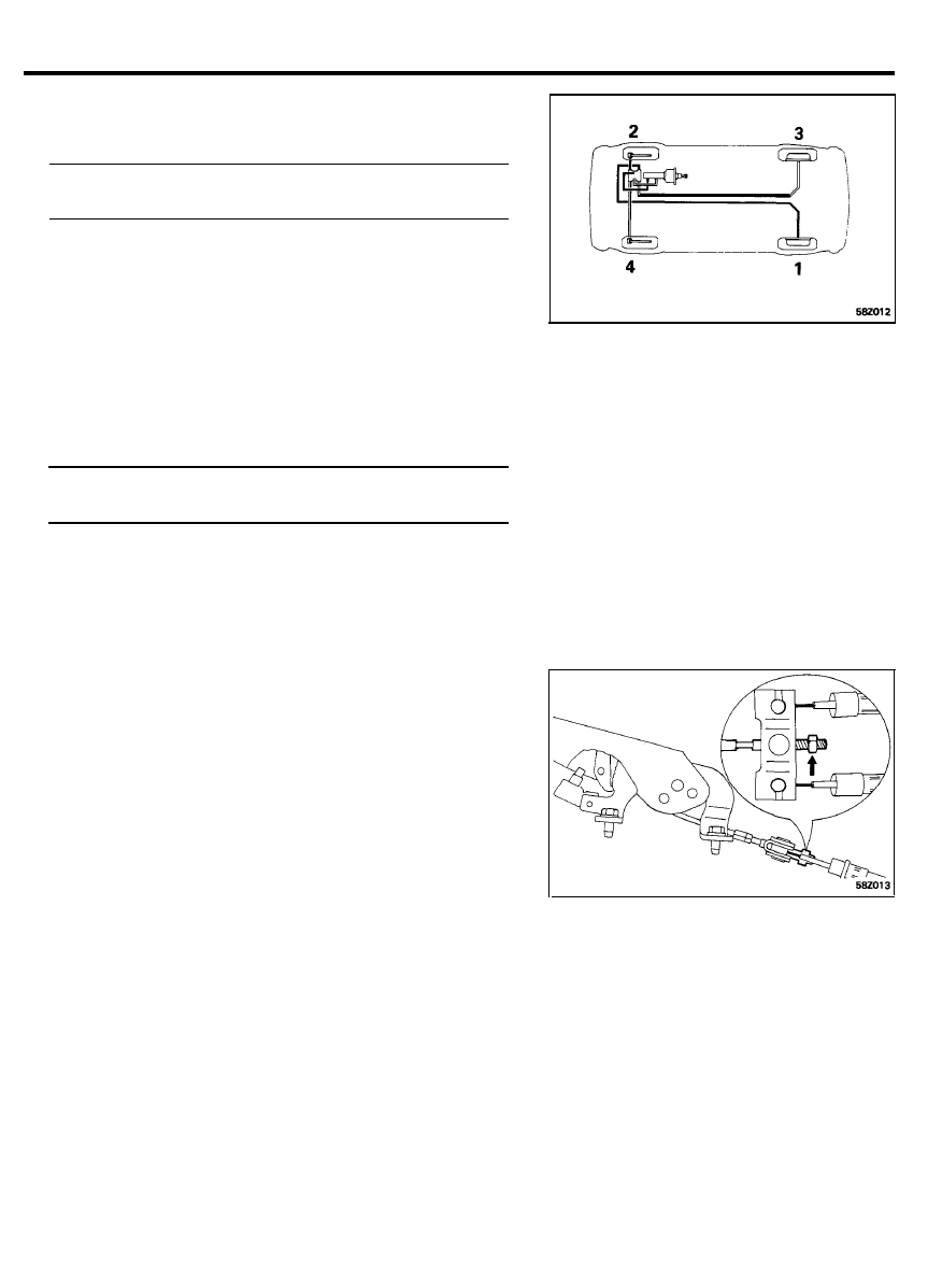
7.
Repeat the above procedure for each wheel in the sequence
shown in the illustration.
PARKING BRAKE STROKE ADJUSTMENT
1.
Pull the brake lever with a force of approximately 20 kg (44
lbs.), and count the number of clicks.
Parking brake lever stroke [Standard value]. . . . . . . . . . . . . .
6-7 clicks
2.
If the number of notches is not within the standard value,
adjust the cable length with the adjusting nut of the
equalizer.
3.
The indicator light will go out when the brake lever is fully
released, and will light with the lever is pulled up one notch.
If it does not operate, check the bulb and/or switch.
4.
After the adjustment, check that the rear brakes do not drag
with the parking brake lever released.
5 8 - 9
BRAKE PEDAL
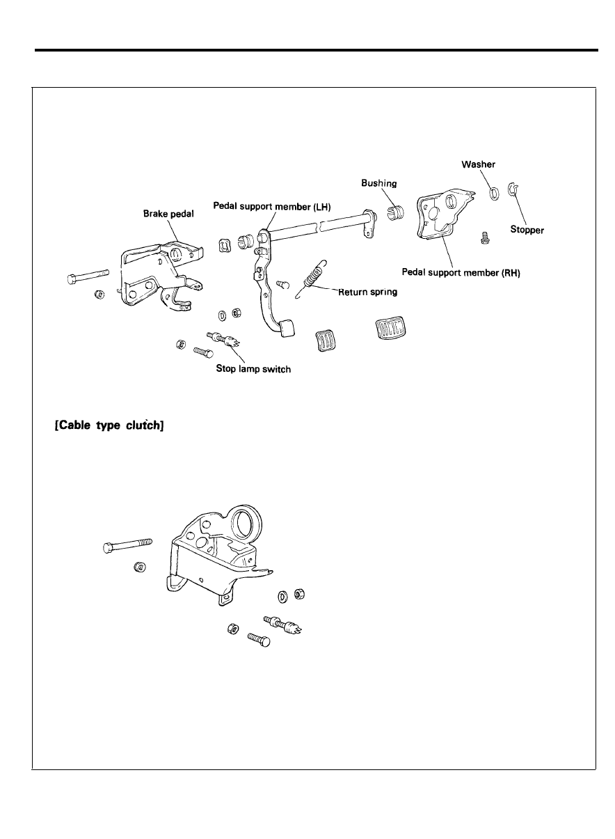
BRAKE PEDAL
COMPONENTS
[Hydraulic type clutch]
5 8 - 1 0
BRAKE PEDAL
REMOVAL
1. Remove the lower crash pad assembly.
2. Remove the steering column shaft mounting bolts (Refer to
Steering Group).
3. Remove the clutch pedal assembly.
4. Remove the console assembly (Refer to Body Group)
5. Remove the glove box housing cover and RH side lower
crash pad.
6. Remove the blower switch and air duct control assembly.
7. Drain the coolant, disconnect the heater hose and remove
the heater unit assembly (Refer to Air Conditioning Group).
8. Remove the stop lamp switch connector.
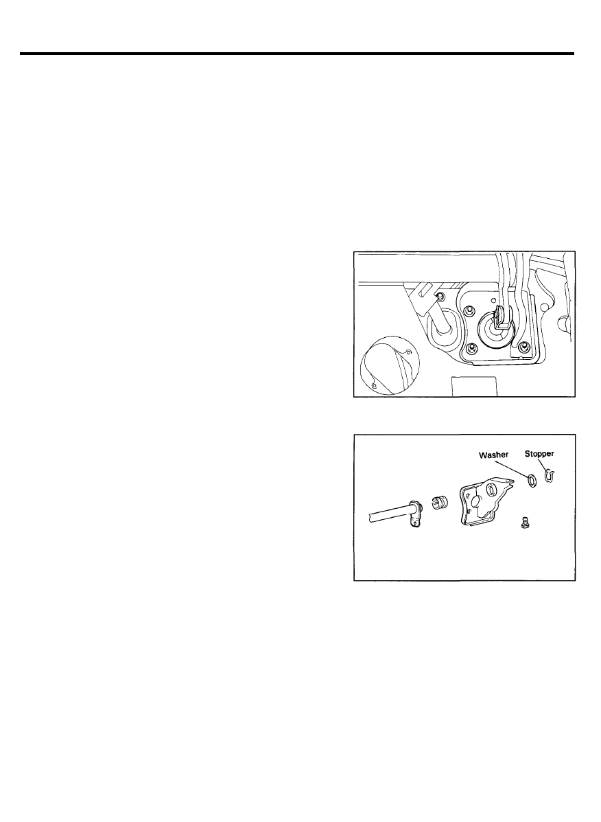
9. Remove the return spring.
10. Disconnect the operating rod and brake pedal from each
other.
11. Remove the stopper and the washer.
12. Loosen the booster mounting nut and remove the right side
pedal support member.
13. Remove the pedal support (left) and remove the pedal from
the left.
5 8 - 1 1
BRAKE PEDAL
INSPECTION
1. Check the bushing for wear.
2. Check the brake pedal for distortion.
3. Check the brake pedal return spring for damage.
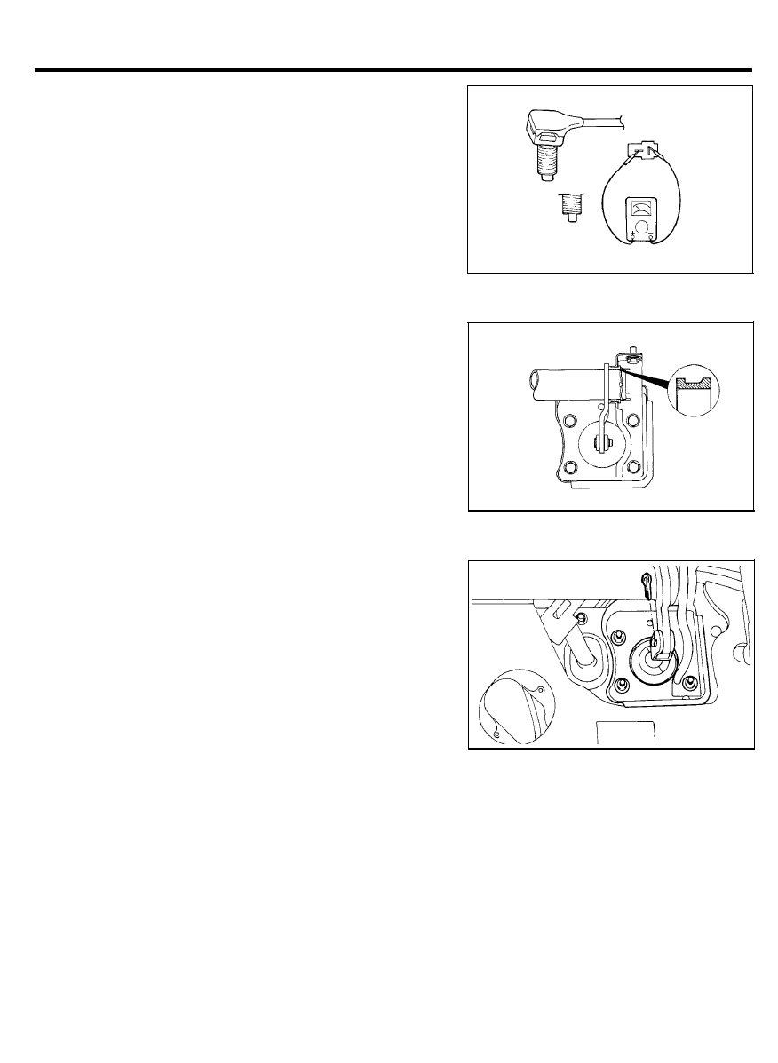
4. Check the stop lamp switch.
1) With an ohmmeter connected to the stop lamp switch
terminals, check for continuity.
2) If there is no continuity when the plunger is depressed
and there is continuity when the plunger is released, the
stop lamp switch is normal.
INSTALLATION
1. Apply chassis grease to the bushing bore and flanges.
NOTE
Install the bushing in the correct position as shown in the
illustration.
2. Apply chassis grease to the sliding surface of the brake pedal
and operating rod clevis pin.
CAUTION
Be sure to install the split pin on the operating rod clevis
pin.
3. Adjust the brake pedal height and free play.
4. Adjust the clutch pedal stroke and free play.
5. Install the steering shaft.
5 8 - 1 2
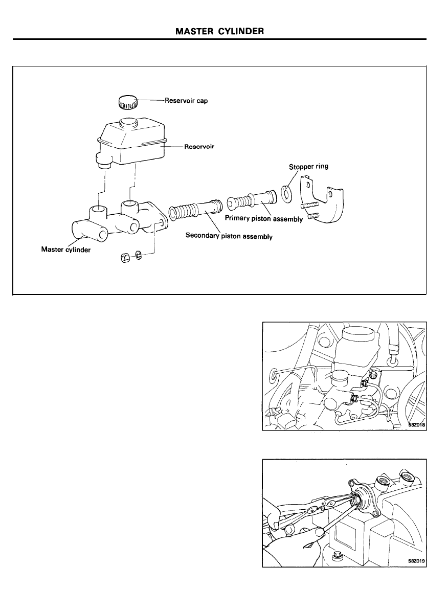
MASTER CYLINDER
COMPONENTS
TORQUE : Nm (kg.cm, lb.ft)
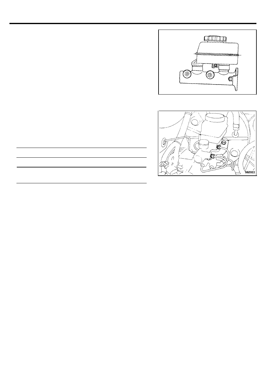
REMOVAL
1. Remove the fluid level warning device connector.
2. Disconnect the brake lines from the master cylinder, and
plug the open ports.
CAUTION
Do not allow brake fluid to remain on a painted surface.
Wash it off immediately.
3. Remove the master cylinder mounting nuts. Disconnect the
proportioning valve mounting bracket, then lift out the
master cylinder.
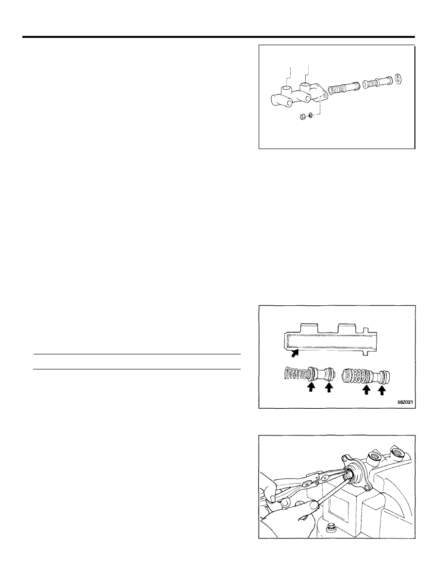
DISASSEMBLY
1. Remove the reservoir cap and drain the brake fluid into a
suitable container.
2. Remove the reservoir from the master cylinder.
NOTE
If necessary, support the master cylinder in a vise at its
flange not at its bore.
3. While depressing the piston, remove the snap ring.
5 8 - 1 3
MASTER CYLINDER
4. Remove the primary and secondary pistons from the master
cylinder body.
NOTE
1) Be careful not to damage the cylinder bore.
2) Do not disassemble the primary and secondary piston
assemblies.
INSPECTION
1. Check the inner surface of the master cylinder body for rust
or scoring.
2. Check the primary and secondary pistons for rust, scoring,
wear, damage or deterioration.
3. Check the primary and secondary piston springs for
deterioration.
ASSEMBLY
1. Apply the specified brake fluid to the inner surface of the
master cylinder body and to the outside of the secondary and
primary pistons.
Recommended brake fluid . . . . . . . . . . DOT 3 or equivalent
2. Carefully insert the spring and secondary piston assembly in
the master cylinder bore.
3. Carefully insert the primary piston assembly in the master
cylinder bore.
4. Depress the primary piston and install the retaining ring in
the cylinder bore groove as illustrated.
5 8 - 1 4
MASTER CYLINDER
5. Install the reservoir cap on the master cylinder.
6. Lubricate the two grommets at both inside and outside with
genuine brake fluid and then insert them into the master
cylinder body.
NOTE
Whenever the reservoir is replaced, the grommets must
also be replaced.
7. Press the reservoir into the grommets with the fluid level
indicator socket facing inboard. The reservoir should snap in
place indicating that it is secure as illustrated.
8. Connect the fluid level warning connector in the socket on
the reservoir.
INSTALLATION
1.
2.
3.
Install the master cylinder on the brake booster with two
nuts.
Nut . . . . . . . . . . . . . . . 8-12 Nm (80-120 kg.cm, 6-9 lb.ft)
Connect two brake tubes and fluid level warning connector.
Brake tube flare nut . . . . . . . . . . . . . . . . . . . . . . . . . . . . . . . . . . . .
13-17 Nm (130-170 kg.cm, 9-12 lb.ft)
Fill the master cylinder reservoir with brake fluid and bleed
the system.
5 8 - 1 5
BRAKE BOOSTER
BRAKE BOOSTER
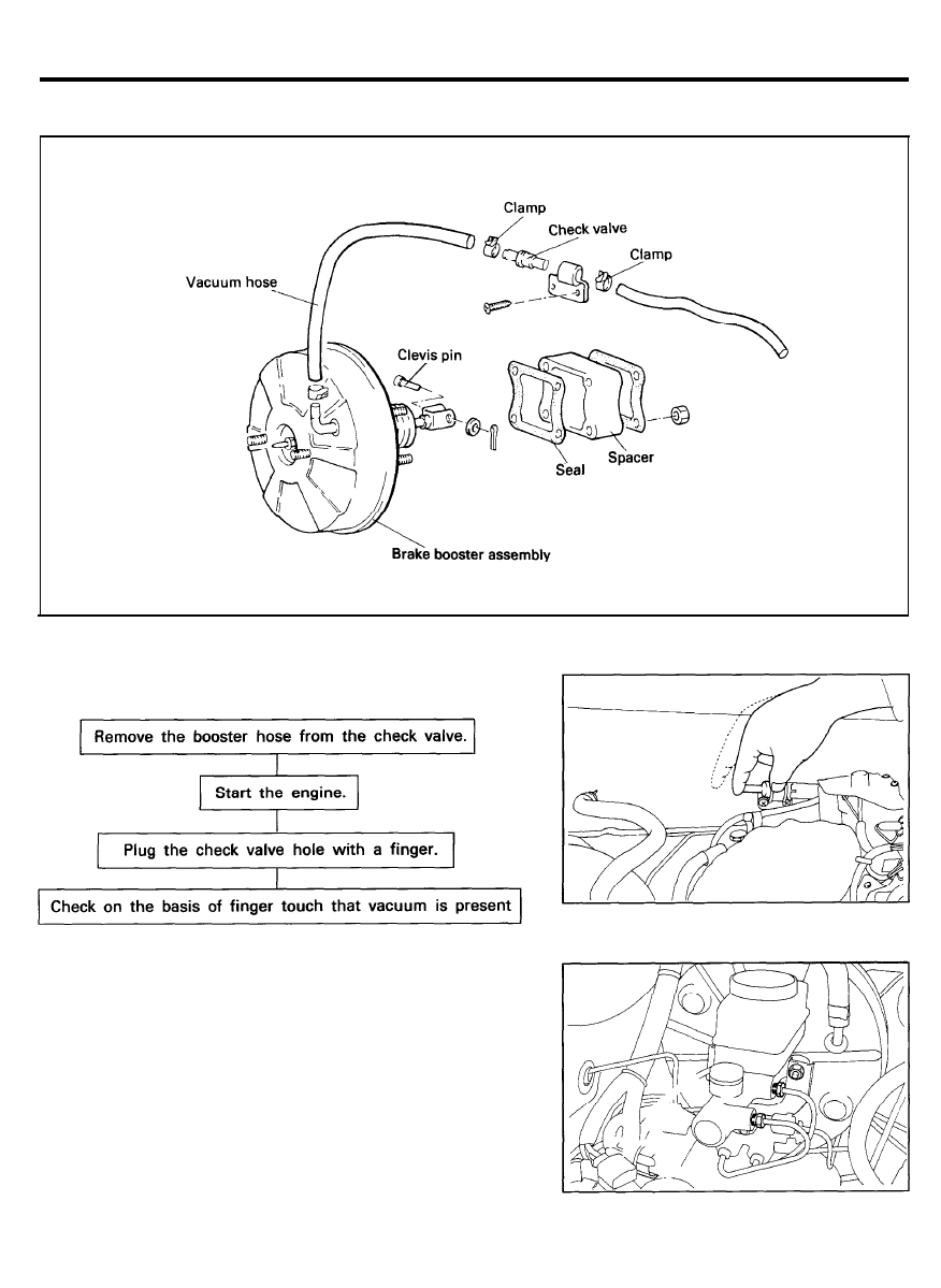
COMPONENTS
TORQUE : Nm (kg.cm, Ib.ft)
CHECK VALVE OPERATION TEST
REMOVAL
1. Remove the master cylinder.
(Refer to page 58-13)
CAUTION
Do not allow brake fluid to remain on a painted surface.
Wash it off immediately
5 8 - 1 6
2. Disconnect the vacuum hose from the booster.
3. Remove the operating rod from the brake pedal.
4. Loosen the booster mounting nuts.
5. Lift out the booster assembly.
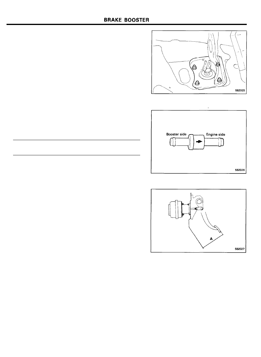
INSTALLATION
1. When the booster assembly is installed, replace the packing
at each end of the booster mounting holder, if necessary.
2. Install brake booster and tighten the mounting nuts.
Tightening torque . . . . . . . . . . . . . . . . . . . . . . . . . . .
8-12 Nm (80-120 kg.cm, 6-9 Ib.ft)
3. Connect clevis to brake pedal with clevis pin and install the
split pin to the clevis pin.
4. Install master cylinder.
5. Connect vacuum hose to brake booster.
6. Pay attention to the direction of the check valve when
installing.
7. Fill brake reservoir with brake fluid and bleed the system.
8. Check for fluid leakage.
9. Check and adjust the brake pedal (Refer to page 58-7).
10. After installation, apply sufficient grease to the clevis and
brake pedal contacting points.
5 8 - 1 7
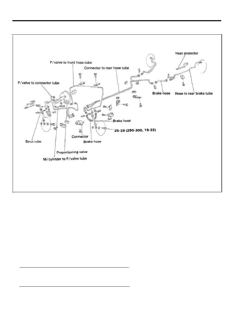
BRAKE LINE
BRAKE LINE
COMPONENTS
TORQUE : Nm (kg.cm, lb.ft)
INSPECTION
1. Check the brake lines for cracks, crimps and corrosion.
2. Check the brake hoses for cracks, damage and leakage.
3. Check the brake line flare nuts for damage and leakage.
INSTALLATION
1. Install the brake hoses without twisting them.
2. The brake lines should be installed away from sharp edges,
weld beads or moving parts.
3. Tighten the connections to the specified torque.
Flare nuts . . . . . 13-17 Nm (130-170 kg.cm, 9-12 Ib.ft)
Brake hose to front caliper . . . . . . . . . . . . . . . . . . . . . . . . . . . . .
25-30 Nm (250-300 kg.cm, 18-22 Ib.ft)
5 8 - 1 8
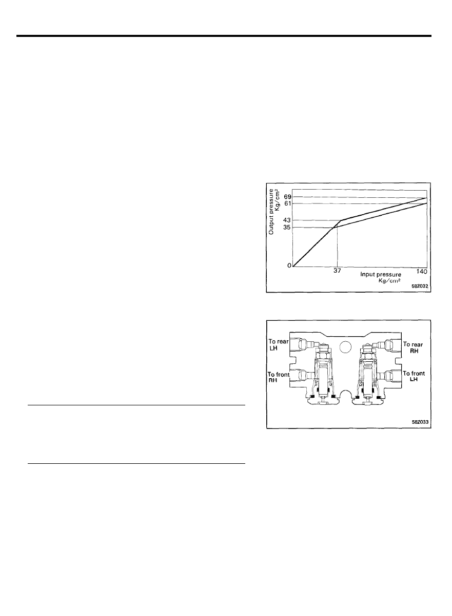
PROPORTIONING VALVE
PROPORTIONING VALVE
Do not disassemble the proportioning valve. The proportioning
valve regulates the distribution of fluid pressure to the front and
rear brakes to prevent skidding in the event of rear wheel lock,
and to obtain greater braking efficiency.
PORPORTIONING VALVE FUNCTION TEST
1.
2.
3.
Connect two pressure gauges, one the input side and one
to the output side of the proportioning valve.
NOTE
Be sure to bleed the system after you connect the pressure
gauges.
With the brakes applied, measure the input pressure and the
output pressure. If the measured pressures are within the
ranges as illustrated, the proportioning valve is good.
Reconnect the brake lines in their original positions and
bleed the system.
NOTE
This figure shows characteristics of the proportioning
valve during pressure increase.
PROPORTIONING VALVE INSTALLATION
1. Install the brake lines according to the illustration.
2. Tighten the flare nuts and bleed the system.
Tightening torque
Brake tube flare nut . . . . . . . . . . . . . . . . . . . . . . . . . . . . . . . . . .
3-17 Nm (130-170 kg.cm, 9-12 lb.ft)
Proportioning valve mounting nut . . . . . . . . . . . . . . . . . . . . .
8-12 Nm (80-120 kg.cm, 5.8-8.7 Ib.ft)
5 8 - 1 9
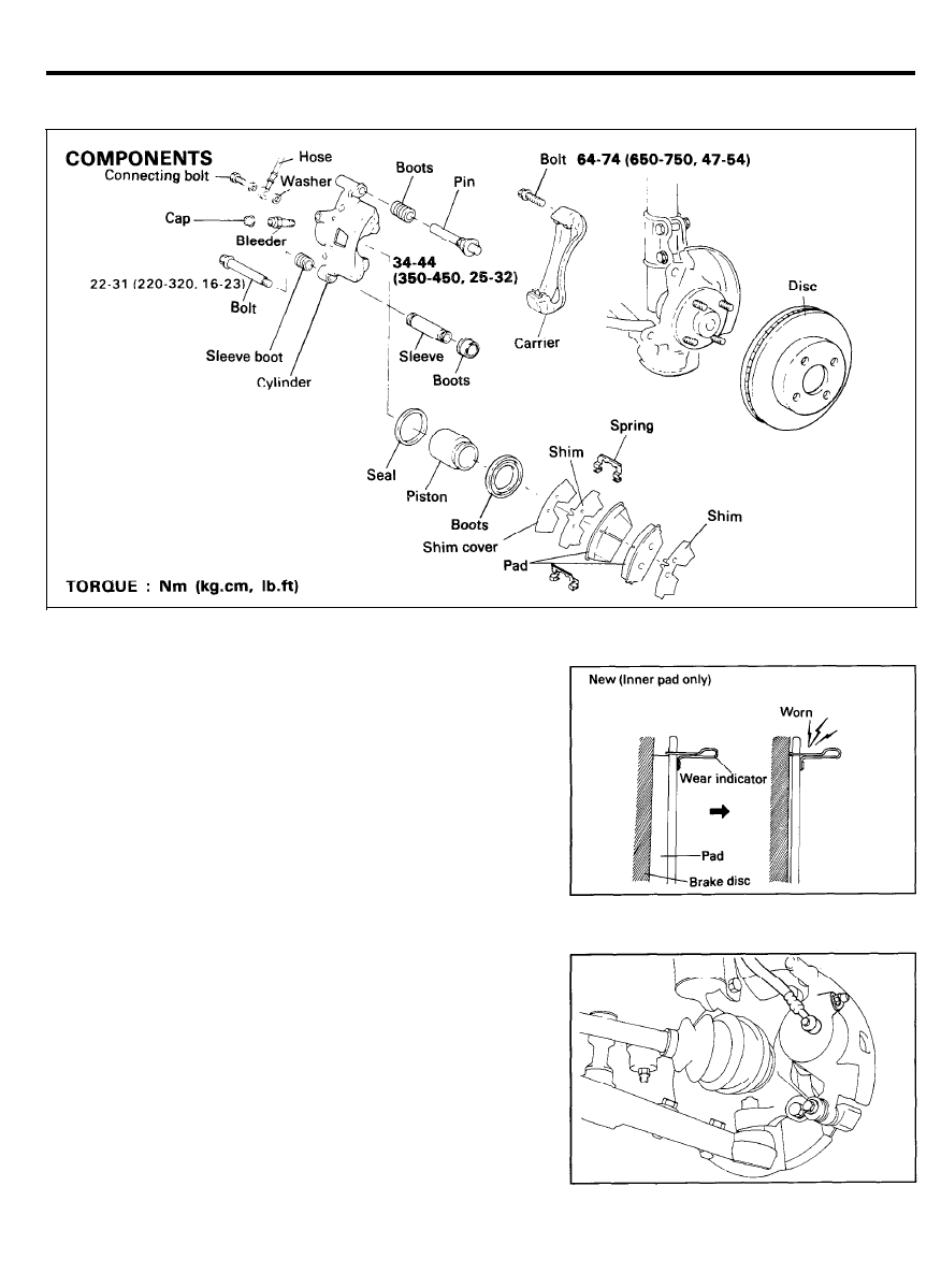
FRONT DISC BRAKE
FRONT DISC BRAKE
REPLACEMENT OF BRAKE PADS
The brake pads have wear indicators that contact the brake disc
when the brake pad thickness becomes 2 mm (0.08 in.). The
wear indicators will generate a squealing sound to warn the
driver.
Removal
1. Remove the lower bolt and lift the caliper assembly up and
out of the way. Secure it with wire or some other retaining
method.
2. Remove the pads.
CAUTION
Do not depress the brake pedal while disassembling the
pads.
5 8 - 2 0
FRONT DISC BRAKE
Inspection
1. Check the pads for wear or oil contamination and replace,
if necessary.
CAUTION
The
pads
for the right and left wheels should be replaced
at the same time. Never “split” or intermix brake pad sets.
All four pads must be replaced as a complete set.
Standard value Service limit
Pad thickness mm (in.)
9.0 (0.394)
1.0 (0.039)
2. Check the shims for damage or deformation.
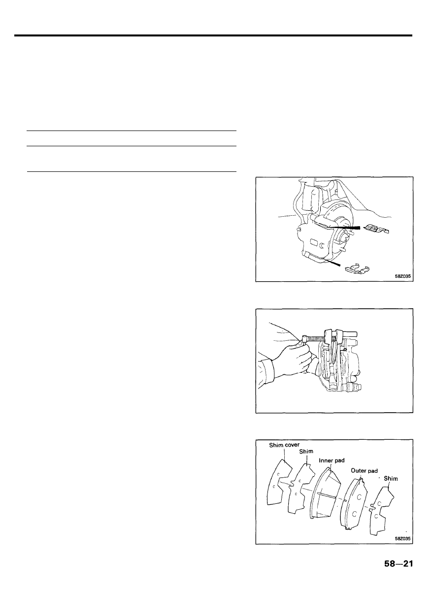
Installation
1. Install the pad clips.
2. Install the pads onto each pad clip.
NOTE
Position the
pad
with its wear indicator toward the disc
side and facing upward.
3. Seat the piston in the cylinder using Special Tool
(09581-11000).
4. Install the new pads. The shims are attached to the each
pad as illustrated.
CAUTION
Never apply grease to the disc or pads.

FRONT DISC BRAKE
5. Install the bolt and tighten to the specified value.
Tightening torque . . . . . . . . . . . . . . . . . . . . . . . . . . . . . . . . . . . . . . .
22-31 Nm (220-320 kg.cm, 16-23 lb.ft)
CALIPER ASSEMBLY
Removal
1. Remove the wheel and tire.
2. Disconnect the brake hose.
3. Remove the pads.
4. Remove the sleeve.
5. Remove the pin boot and sleeve boot.
6. Remove the caliper assembly.
Disassembly
1. Remove the piston boot.
2. Remove the piston using compressed air.
C A U T I O N
1) Do not place fingers in front of the piston when using
compressed air.
2) Be careful not to splatter the brake fluid.
3. Remove the piston seal from the caliper using a screw driver.
5 8 - 2 2
FRONT DISC BRAKE
INSPECTION
1. Check the cylinder for wear, damage, cracks and rust.
2. Check the piston for rust, damage, cracks and wear on the
outer surface.
3. Check the sleeve and pin for damage and rust.
4. Check the pad spring and boots for damage.
5. Check the carrier for damage, rust, wear and cracks.
CAUTION
1) Do not use sand paper on the piston surface.
2) All rubber parts must be replaced with new ones.
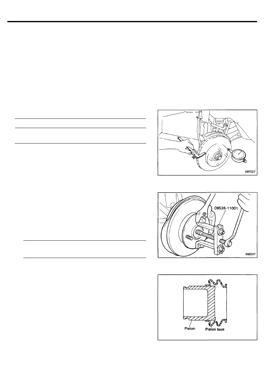
6. Inspect the disc using calipers and dial gauge.
Standard value Service limit
Thickness of disc mm (in.)
19 (0.75)
17 (0.67)
Runout of disc mm (in.)
0.15 (0.006)
7. If necessary, replace the brake disc.
1) Remove the torque plate from the knuckle and suspend
it with a wire.
2) Using special tool (09526-11001), disconnect the
driveshaft from the hub, and remove the brake disc and
hub.
3) Install the brake disc and hub assembly to the axle shaft.
4) Install the axle nut and washer, then tighten the axle
nut.
Tightening torque . . . . . . . . . . . . . . . . . . . . . . . . . . . . . . . . . . .
196-255 Nm (2000-2600 kg.cm, 145-188 Ib.ft)
5) Install the torque plate onto the knuckle.
ASSEMBLY
1. Clean all components with isopropyl alcohol except the pads
and shim.
2. Apply rubber grease to the piston seal and install the piston
seal in the cylinder.
5 8 - 2 3
FRONT DISC BRAKE
3. Assemble the piston and piston boots according to the
following procedure.
1) Apply rubber grease to the caliper bore, outside surface
of the piston and piston boot.
2) Install the piston boot on the piston as illustrated.
3) Insert the piston boot in the inner groove of caliper and
slide the piston into the caliper.
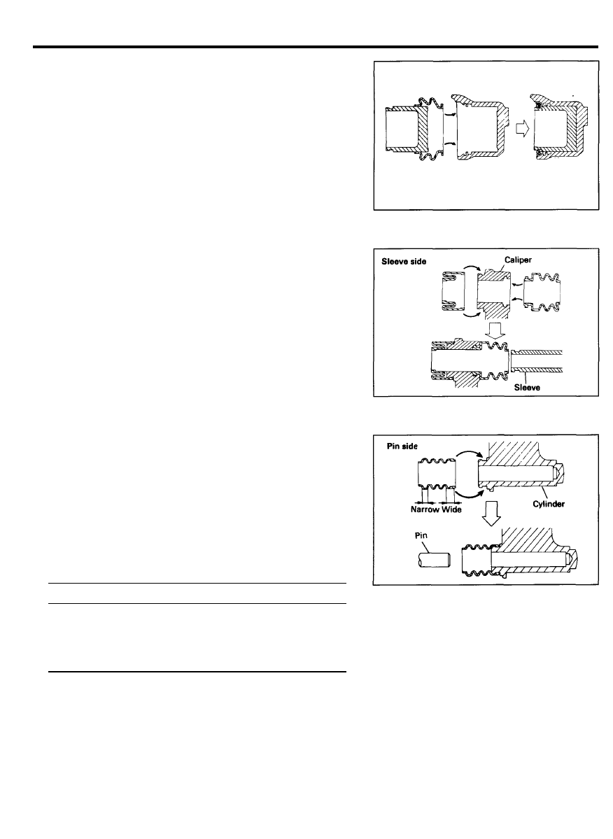
4. Assemble the sliding parts according to the following
procedure.
1) Apply rubber grease to the outside surface of the sleeve
and pin, pin and sleeve bore of the caliper, pin boot and
sleeve boot.
2) Insert the boots into the groove of the caliper.
5. Install the pads.
NOTE
Do not apply grease to the disc or pads.
6. Tighten the brake hose connecting bolt.
Tightening torque
Nm (kg.cm, Ib.ft)
Sliding pin
3 4 - 4 4 ( 3 5 0 - 4 5 0 , 2 5 - 3 3 )
Sliding bolt
2 2 - 3 1 ( 2 2 0 - 3 2 0 , 1 6 - 2 3 )
Carrier mounting bolt
6 4 - 7 4 ( 6 5 0 - 7 5 0 , 4 7 - 5 4 )
Brake hose mounting oil bolt
2 5 - 2 9 ( 2 5 0 - 3 0 0 , 1 8 - 2 2 )
NOTE
1) Check that the surfaces of the pin and bolts are not
damaged before tightening.
2) Bleed the system.
Depress the pedal several times and check for fluid
leakage from all connecting parts.
5 8 - 2 4
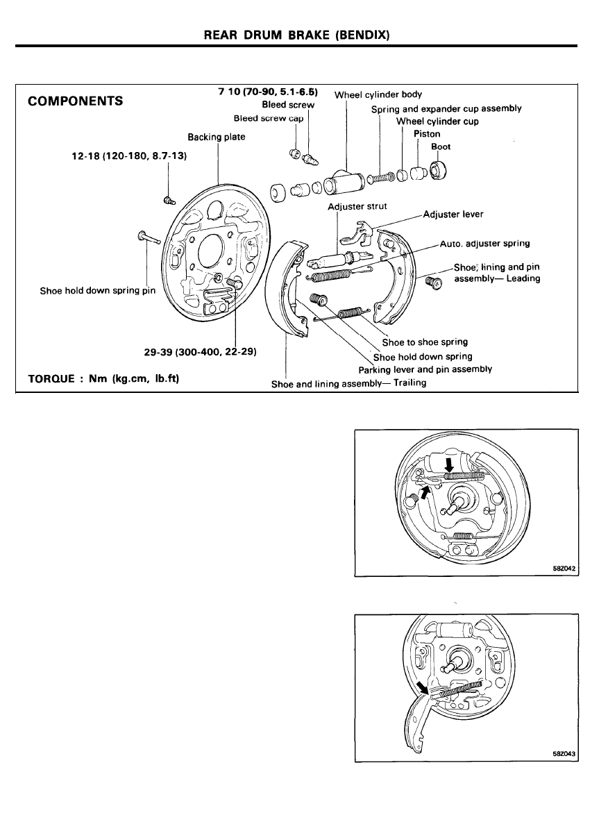
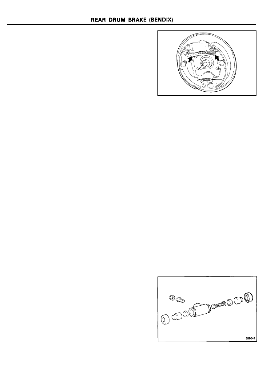
REAR DRUM BRAKE (BENDIX)
REMOVAL
1. After removing the wheel, remove the brake drum.
2. Remove the automatic adjuster spring and adjuster lever.
3. Spread the shoes and remove the adjuster strut.
4. Remove the shoe to shoe spring and shoe hold down spring.
5. Remove the parking cable at the parking lever.
6. Remove the clip on the parking brake cable at the backing
plate.
7. Remove the brake line from the wheel cylinder.
8. Remove the wheel cylinder assembly together with the
backing plate.
5 8 - 2 5
REAR DRUM BRAKE (BENDIX)
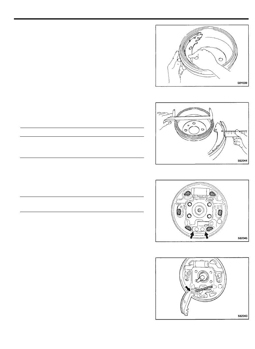
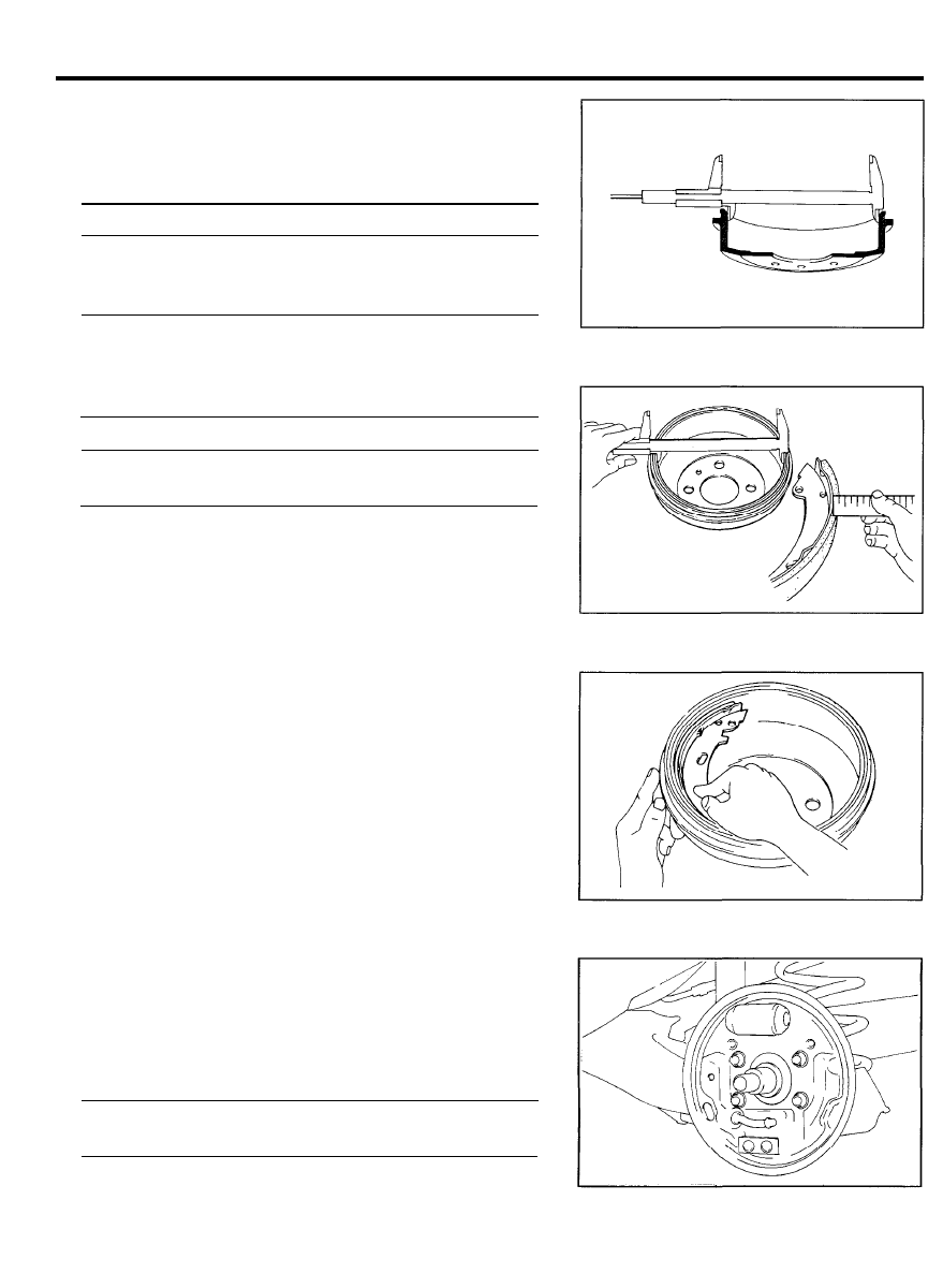
INSPECTION
1. Inspect the backing plate for distortion and damage.
2. Inspect the wheel cylinder for excessive corrosion or
damage.
3. Inspect the brake lining and drum for proper contact.
4. Inspect the brake lining for wear or oil contamination.
5. Measure the brake drum inside diameter.
Check the runout of the brake drum using a dial indicator.
6. Measure the brake shoe lining thickness.
mm (in.)
Standard value
Service limit
Drum inside diameter
180 (7.087)
182 (7.165)
Brake drum runout
-
0.015 (0.0006)
Lining thickness
4.85 (0.191)
0.8 (0.039)
INSTALLATION
1. Apply a light coating of lubricant to the illustrated surfaces.
Recommended lubricant . . . . . . . . . . . . . . . . . . . . . . . . . . . . . . . .
Wolfracote grease per ES-2825 or equivalent
1) Six ledges of the backing plate.
2) Where shoe web (anchor end) contacts anchor plate.
3) Where automatic adjuster lever contacts adjuster socket
and automatic adjuster pin.
4) Where parking parke lever contacts shoe web (strut
area).
2. Attach the parking brake cable to the parking brake lever and
install the clip at the backing plate.
3. Install the brake shoes with the shoe hold down springs.
4. Connect the shoe to shoe spring.
5 8 - 2 6
5. Install the adjuster strut assembly between the leading shoe
slot and the slot in the trailing shoe and the parking brake
lever.
6. Install the adjuster lever in the groove located in the adjuster
pin and into the slot of the adjuster socket that fits into the
leading shoe web.
NOTE
The adjuster pivot nut blade is marked R or L for right hand
and left hand brake assemblies. The pivot nut must be
installed with the groove on the side of the blade facing
outward.
7. Attach the adjuster spring.
8. Install the backing plate and tighten the bolts.
9. Install the brake drum and wheel/tire assembly.
REPLACEMENT OF WHEEL CYLINDER
Wheel cylinders should not be disassembled unless they are
leaking. Carefully pull the lower edges of the wheel cylinder
boots away from the cylinder, and note whether or not the
interior is wet with brake fluid. Excessive fluid at this point
indicates leakage past the piston cups and a need for wheel
cylinder overhaul.
DISASSEMBLY AND INSPECTION
1. Remove the brake shoes as outlined before.
2. Remove the boots and pull out the pistons, cups, spring and
expander assembly.
3. Remove the bleeder screw from the cylinder.
4. Inspect the pistons for scoring or other visible damage.
Replace, if necessary.
5. Inspect the cylinder bore for scoring or rust.
5 8 - 2 7

REAR DRUM BRAKE (BENDIX)
ASSEMBLY
1.
2.
3.
4.
Apply a light coat of brake fluid (DOT 3) to all internal parts.
Install the bleeder screw into the cylinder and tighten to
specifications.
Insert the return spring and cup expander assembly, cups
and pistons into their respective position in the cylinder bore.
Place a boot over each end of the cylinder.
NOTE
Ensure that the brake line is installed in the lower wheel
cylinder port and the bleed screw in the upper port.
Bleed the brake system.
5 8 - 2 8

REAR DRUM BRAKE (MANDO)
COMPONENTS
TORQUE : Nm (kg.cm, Ib.ft)
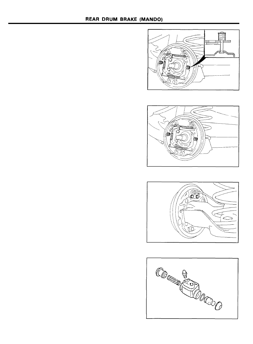
REMOVAL
1. Removing the wheel and tire, then remove brake drum.
NOTE
If the brake drum is difficult to remove, insert bolts into
the threaded holes of the drum then remove it.
2. After removing the nut, remove the rear hub with the brake
drum.
3. Remove the abut end shoe spring, shoe hold down spring.
4. Remove the shoes and adjuster as an assembly.
5 8 - 2 9
REAR DRUM BRAKE (MANDO)
INSPECTION
1. Measure the brake drum inside diameter.
Check the runout of brake drum using a dial indicator.
mm (in.)
Standard value
Service limit
Inside diameter
180 (7.1)
182 (7.165)
Out-of-rounded of brake
-
0.015 (0.0006)
drum
2. Measure the brake shoe lining thickness.
Standard value
Service limit
Lining thickness
mm (in.)
Leading-4.5 (0.177)
Trailing-4.6 (0.181)
1.0 (0.039)
3. Inspect the brake lining and drum for proper contact.
4. Inspect the wheel cylinder outside for excessive corrosion
5. Inspect the backing plate for wear or damage.
and damage.
INSTALLATION
1. Apply the specified grease to the locations indicated in the
illustration and to each component.
o Shoe and backing plate contact surfaces
o Shoe and anchor plate contact surfaces
Recommended grease . . . . . . . . . . . . . . . . . . . . . . . . . . . . . . . . . .
Multipurpose grease SAE J310, NLGI No.2
5 8 - 3 0
2. Install the shoe hold down pin.
3. Assemble the return spring with the push rod shortened.
4. After assembling the drum components, pull the parking
brake lever all the way up several times.
WHEEL CYLINDER REPLACEMENT
1. Remove the brake shoe.
2. Disconnect the brake tube.
3. Remove the wheel cylinder assembly.
4. Remove the duct boot.
5. Remove the piston and piston cup.
6. Drive out the return spring.
5 8 - 3 1
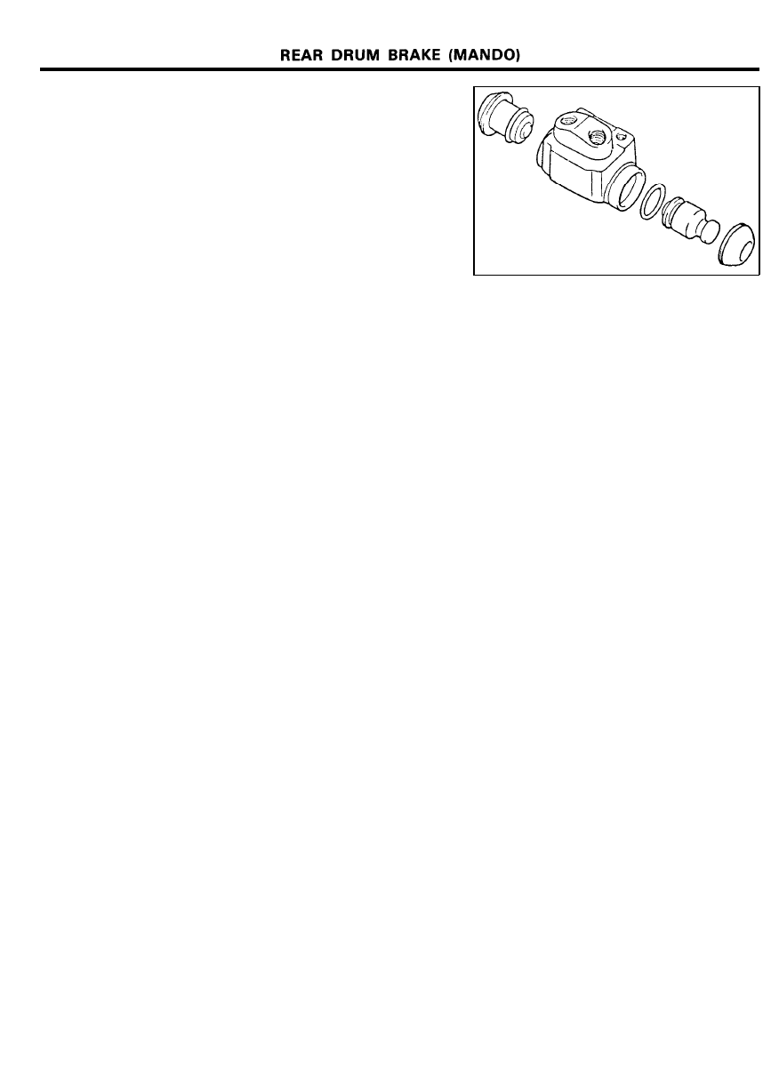
7. Before assembling the wheel cylinder, inspect the following
points.
1) Check the cylinder and piston for wear, damage and rust.
2) Check the cylinder body for damage and cracks.
3) Check the contact surface of the piston and shoes for
wear.
4) Check the piston spring for looseness.
8. Assembly is the reverse of the removal procedure.
NOTE
1) Clean the cylinder and inner part with isopropyl alcohol
before assembly.
2) Apply enough brake fluid to piston cups and cylinder.
3) Be sure to use new piston cups and dust boots.
Caution
Be careful not to lose the steel ball in the bleeder.
5 8 - 3 2
PARKING BRAKE
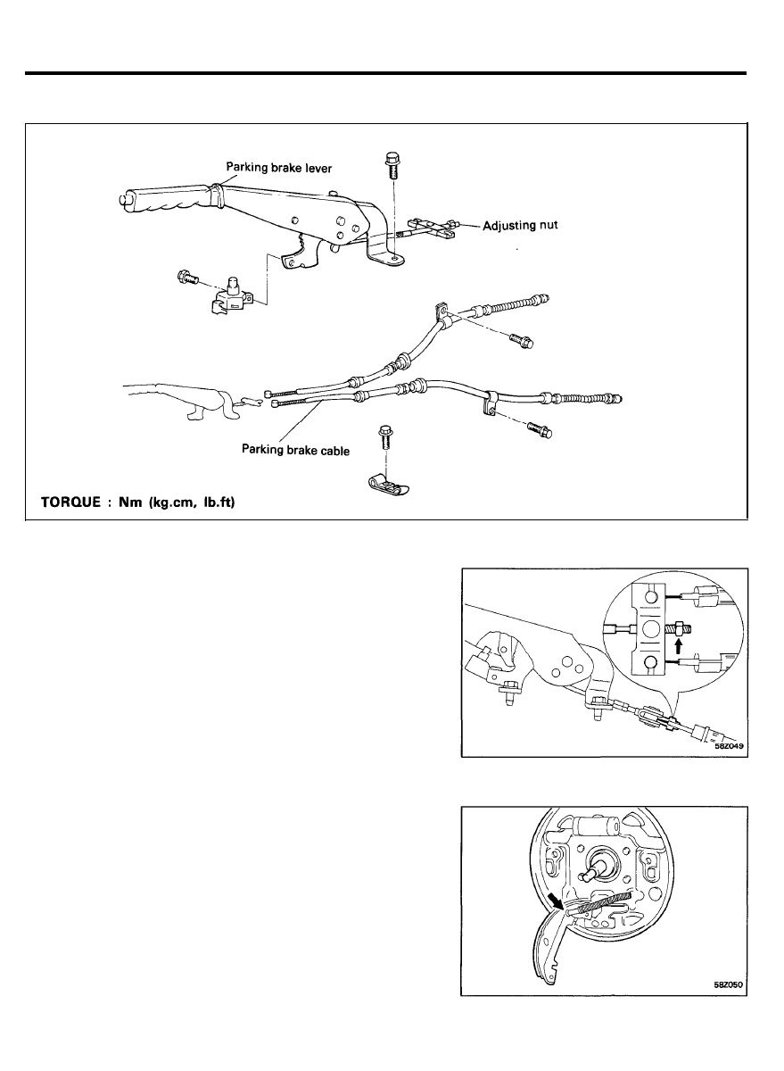
PARKING BRAKE
COMPONENTS
REMOVAL
1. Remove the rear console.
2. Loosen the adjusting nut and detach the parking brake cable.
3. Detach the parking brake switch assembly.
4. Remove the parking brake lever assembly.
5. Remove the wheel and tire.
6. Remove the brake drum.
7. Remove the brake shoes as outlined before.
8. Detach the parking brake cable from the parking lever.
5 8 - 3 3
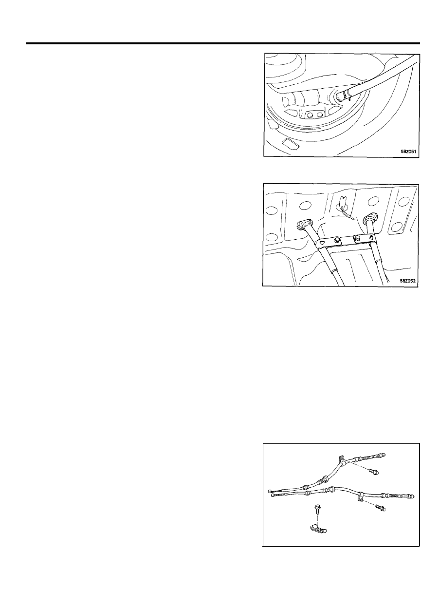
PARKING BRAKE
7. Remove the parking brake cable retaining ring in the rear
of the backing plate.
8. Remove the rear seat cushion assembly and roll up the
carpet.
9. Loosen the parking brake cable clamp and remove the
parking brake cable assembly.
INSPECTION
1. Check the parking brake switch operation.
2. Check the parking brake lever ratchet for wear.
3. Check the parking brake cable for fraying or damage.
INSTALLATION
1. Check the parking brake cables for left and right
identification marks and install accordingly.
5 8 - 3 4
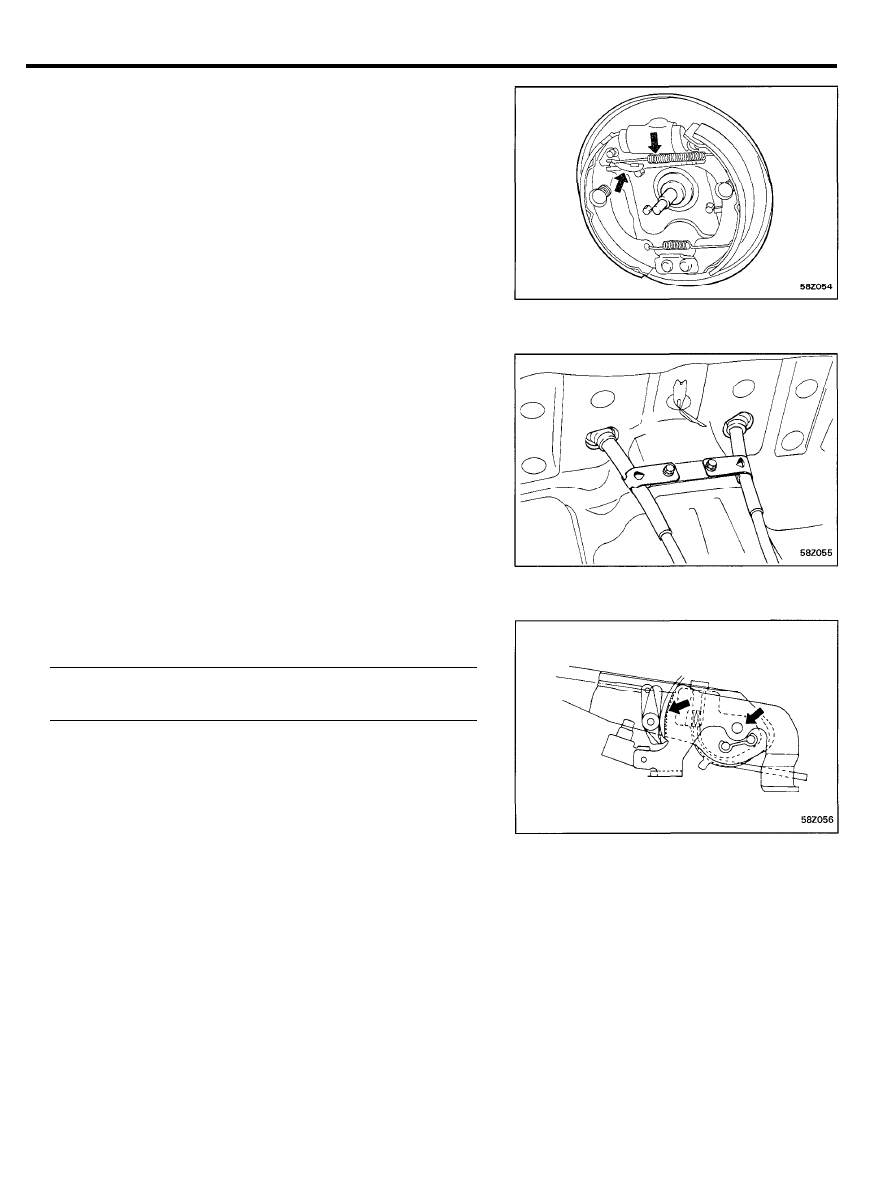
PARKING BRAKE
2. Move the adjuster lever all the way back when installing the
shoe-to-shoe spring.
3. Install the grommets in
the direction shown in the
illustration.
4. Apply a coating of the specified grease to the sliding parts
of the ratchet plate and ratchet pawl.
Specified grease . . . . . . . . . . . . . . . . . . . . . . . . . . . . . . . . . . . . . . . .
Multipurpose grease SAE J310, NLGl No.2
5. After installing the cable adjuster, adjust the parking brake
lever stroke.
5 8 - 3 5
Wyszukiwarka
Podobne podstrony:
Soisk6.12.2007, SYSTEMY
12. Pieniądz i system bankowy, Mikroekonomia mgr Grażyna Karwacka
12 wspomaganie systemu operacyjnego pamiec wirtualna
12 zintegrowane systemy logistyczne
9 12 10r systemy
ETP wyklad 12 elektroniczne systemy pomiaru katow
5 12 2 Ergonomia systemow sterowania
12 Instalowanie systemow projek Nieznany
(12) Lojalnościowe systemy rabatowe muszą być zgodne z prawem konkurencji
Test 12, GWSH, system turystyczny
12 13 Systemy plikow i Struktura HDD
13 Brake System
12 - Sieciowe Systemy Operacyjne II, ARS
12, Notatki z systemów
System finansowy przedsiebiorstwa (12 stron), T 7 SYSTEM FINANSOWY PRZEDSIĘBIORSTWA
Popular Mechanics Flushing Your Brake System
TPL WYK 13 12 20 System terapeutyczny
więcej podobnych podstron