277
In This Chapter
17
Calculating Screw
Connections
In this tutorial, you can calculate a screw connection
using the stand-alone screw calculation function in
AutoCAD
®
Mechanical 6.
■
Starting the screw calculation
■
Selecting and specifying a screw
■
Selecting and specifying a nut
■
Selecting and specifying a washer
■
Specifying the plate geometry
and properties
■
Specifying the contact area
■
Specifying the loads and
moments
■
Specifying the settlement
■
Specifying the tightening
■
Creating and inserting the result
block

278
|
Chapter 17
Calculating Screw Connections
Key Terms
Term
Definition
axial force
A force parallel to the screw axis
contact area
The touching surfaces of the plates which are effective for the calculation
safety factor
The safety factor is the ratio of effective load and safe load
shear force
A force perpendicular to the screw axis
stress
A force or pressure on a part. Stress is the force per area
Methods for Calculating Screws
|
279
Methods for Calculating Screws
The Screw Calculation provides two different ways to calculate a screw
connection:
■
Stand-alone calculation: All data and properties are specified by the user.
■
Calculation of an existing screw connection: The user selects an existing
screw connection to be calculated. All geometrical and standard-related
data is taken from the screw connection and cannot be edited.
In this exercise, we use the stand-alone Screw Calculation. The stand-alone
calculation enables you to calculate a screw connection without any prereq-
uisites. You can specify the screw connection in detail (material, geometric,
load, settlement and tightening properties). In this exercise, you are provided
with the drawing of a screw calculation. Some values will be selected from
tables, some will be entered manually, and some will be taken directly from
the drawing.
Open the initial drawing.
To open a drawing
1
Open the file tut_ex19 in the acadm\tutorial folder.
Menu
File ➤ Open
Command
OPEN
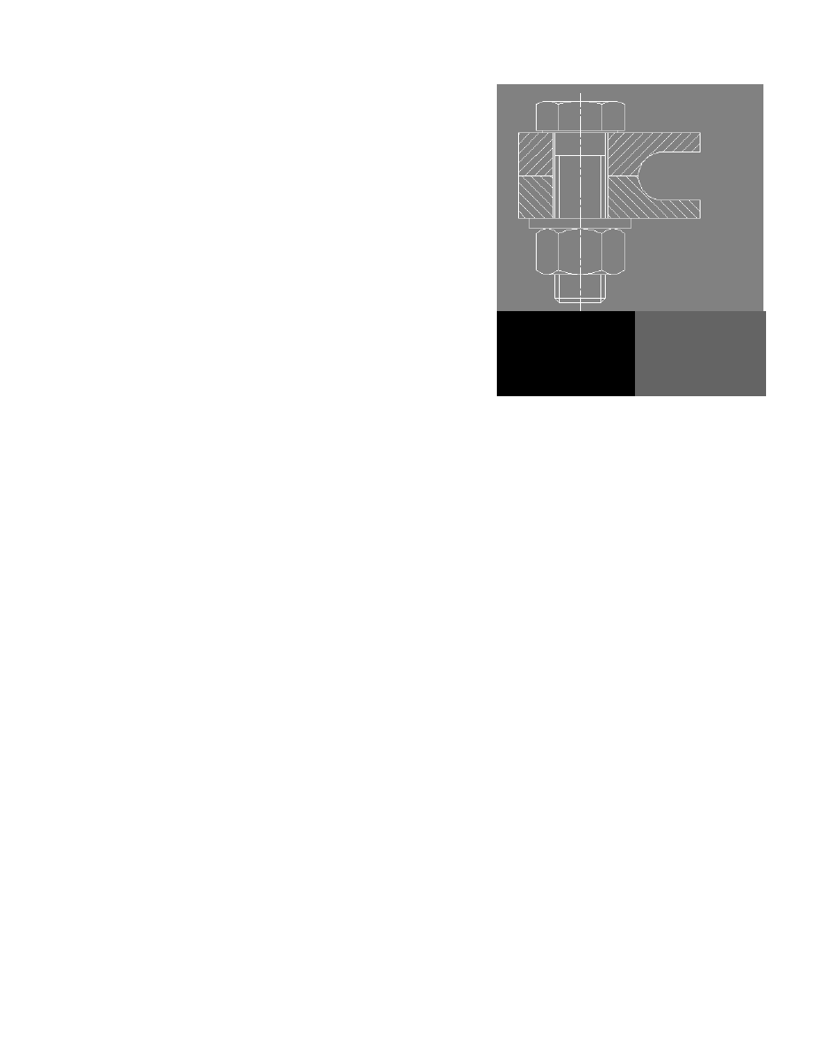
The drawing contains the representation of a screw connection.
Save your file under a different name or to a different directory to preserve
the original tutorial file.
280
|
Chapter 17
Calculating Screw Connections
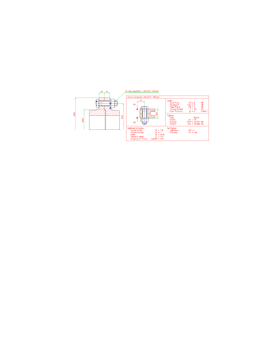
Terms of reference:
Two hollow shafts made of Cq 45 with forged coupling flanges are to be con-
nected by 13 hex-head bolts ISO 4017 M12 x 45 - 10.9, which are arranged
at a pitch diameter of 130 mm. The through holes are according to ISO 273
close. The bolts are safeguarded against loosening by gluing the threads (
µ
=
0.14). The tightening takes place manually using a torque wrench (k = 1.8).
The flanged connection is to be designed for a alternating torque of T = 2405
Nm and non-skid (seal safety of plates
≥
1).
Using Stand Alone Screw Calculations
First, you have to start the Screw Calculation.
To start the Screw Calculation
1
Start the Screw Calculation command.
Menu
Content ➤ Calculations ➤ Screw Calculation
Command
AMSCREWCALC
2
Respond to the prompts as follows:
Select screw connection <Stand alone calculation>:
Press
ENTER
The Screw Calculation dialog box opens. Now, you have to specify the screw
connection.
Selecting and Specifying Screws
In this section of the screw calculation, you can select the screw standard and
size as well as the material properties. You are also able to enter the geomet-
rical properties of a user-defined screw, for example in detail.
Now, select and specify the screw.
Using Stand Alone Screw Calculations
|
281
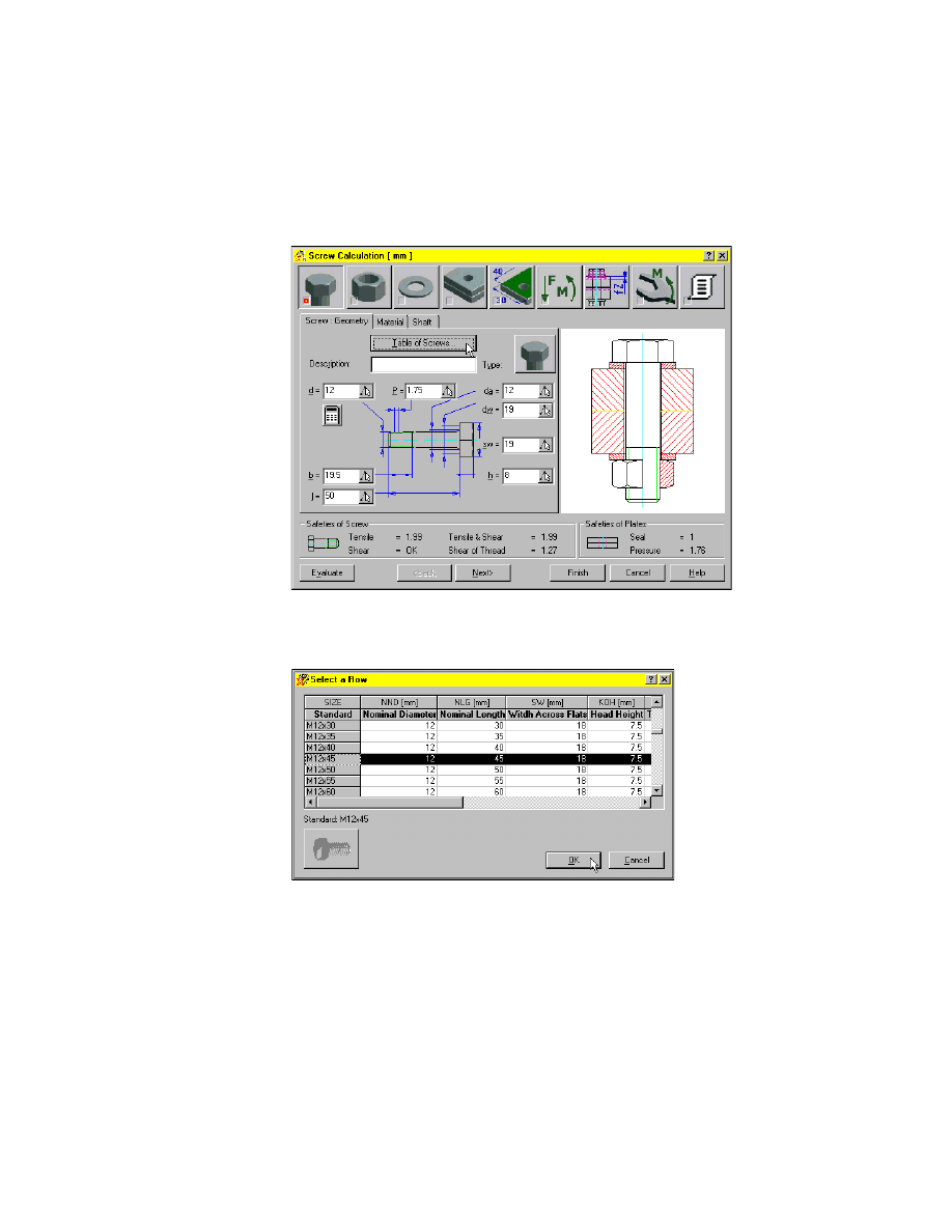
To specify a screw
1
On the Screw: Geometry tab, choose Table of Screws.
2
In the Select a Screw dialog box, choose Hex Head Types and ISO 4017 (Regular
Thread).
3
In the Select a Row dialog box, choose the standard M12x45. Choose OK.
Now, the geometrical values of the standard screw ISO 4017 M12x45 are
entered and you have to specify the property class.
282
|
Chapter 17
Calculating Screw Connections
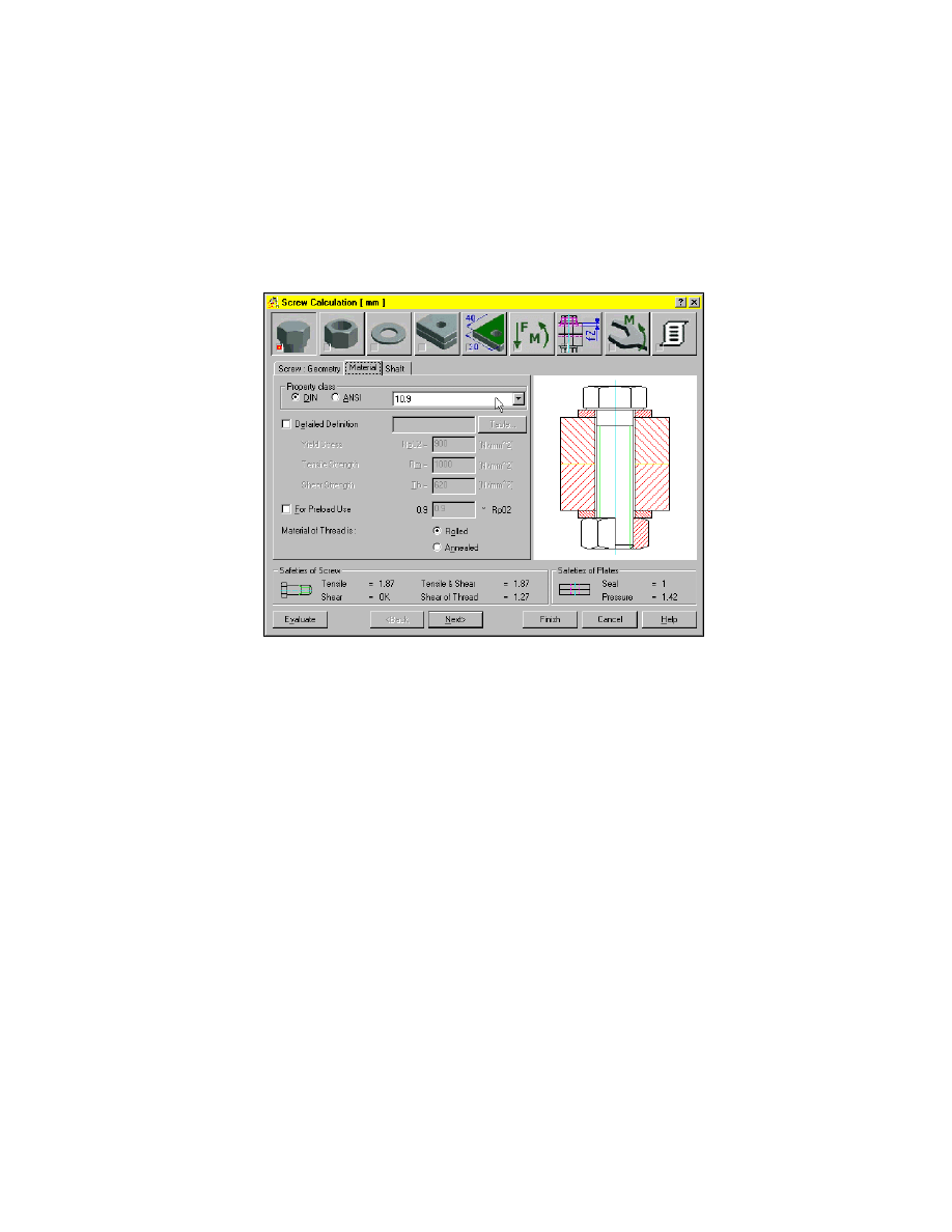
4
Choose the Screw: Material tab.
5
In the property class section, specify:
Standard:
DIN
Property class:
10.9
With this, the screw is specified completely and you have to specify the nut.
6
Choose Next or the Definition of NUT icon in the top row to proceed.
Using Stand Alone Screw Calculations
|
283
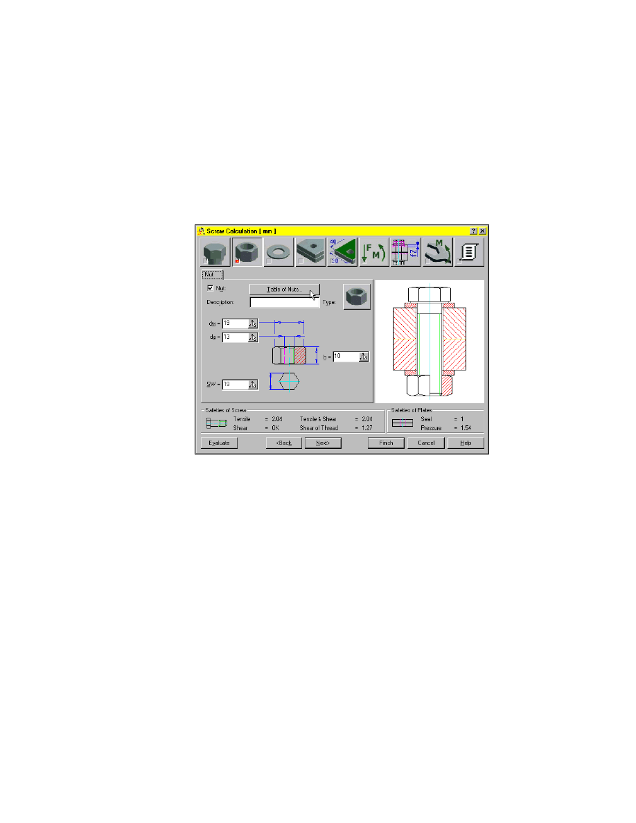
Selecting and Specifying Nuts
In this section of the screw calculation, you can select the nut standard and
size.
To specify a nut
1
On the Nut tab, choose Table of Nuts.
2
In the Select a Nut dialog box, choose Hex Nuts and ISO 4032 (Regular
Thread).
You don’t have to specify a size, because the size is determined by the screw
size.
Now, you have to specify the washers.
3
Choose Next or the Definition of WASHERS icon in the top row to proceed.
284
|
Chapter 17
Calculating Screw Connections
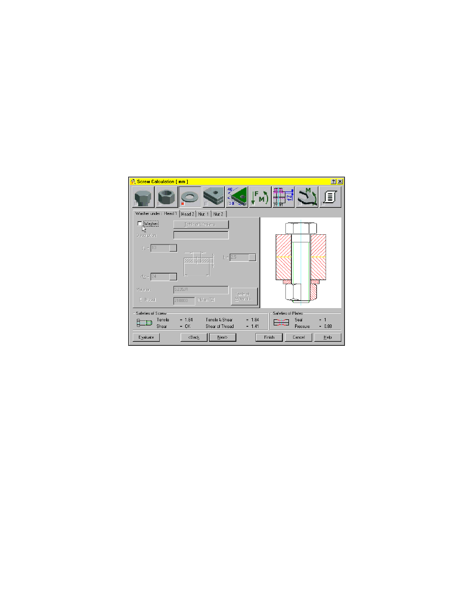
Selecting and Specifying Washers
In this section of the screw calculation, you can select the washer standard
and size as well as the positions of the washers.
To specify a washer
1
Choose the Washer under: Head 1 tab.
2
Clear the check box Washer.
3
Choose the Washer under: Nut 1 tab.
4
Choose Table of Washers.
5
In the Select a Washer dialog box, choose ISO 7091.
Now, you have to specify the plates.
6
Choose Next or the Definition of PLATES icon in the top row to proceed.
Using Stand Alone Screw Calculations
|
285
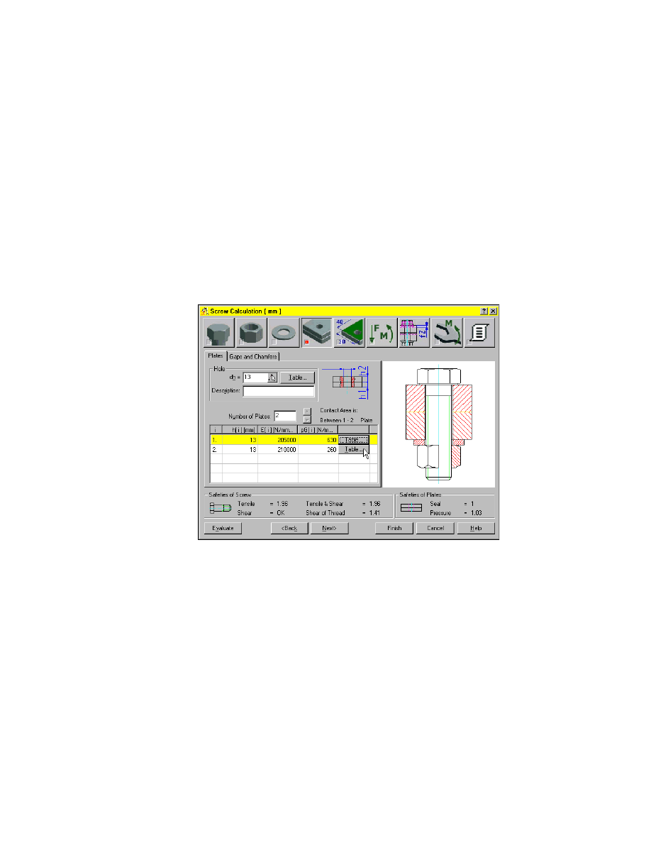
Specifying Plate Geometry and Properties
In this section of the screw calculation, you can select the plate materials and
their geometric properties.
To specify the plates
1
On the plates tab, specify:
Hole diameter dh:
13
Number of Plates:
2
Height of plate 1 h1:
13
Height of plate 2 h2:
13
2
For the definition of both plate materials, choose Table.
3
In the dialog box, choose DIN material.
4
Choose the material Cq 45. Choose OK.
Now, you have to specify the contact area.
286
|
Chapter 17
Calculating Screw Connections
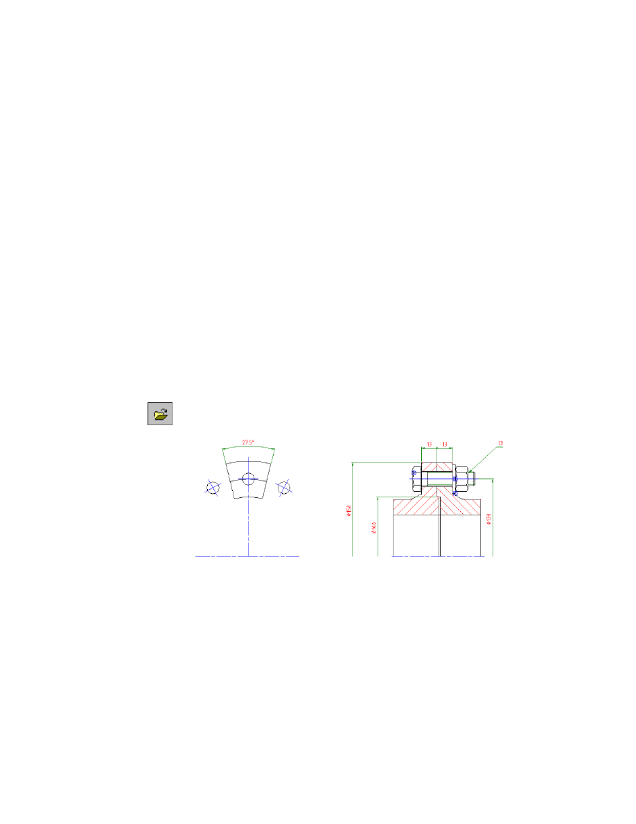
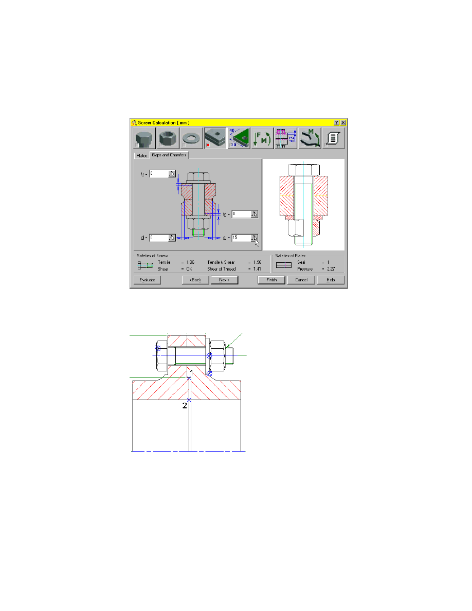
5
Choose the Gaps and Chamfers tab and choose the pick button of the
value gr.
6
Respond to the prompts as follows:
Specify first point:
Select the point (1)
Second point:
Select the point (2) as shown in the following figure
7
Choose Next or the Definition of CONTACT AREA icon in the top row to
proceed.
Using Stand Alone Screw Calculations
|
287
Specifying Contact Areas
In this section of the screw calculation, you can specify the geometric prop-
erties of the contact area.
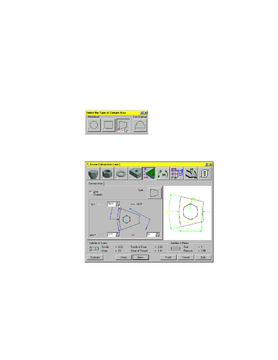
To specify the contact area
1
On the contact area tab, choose the Type of Contact Area icon.
2
In the Select the Type of Contact Area dialog box, choose the third of the
predefined icons.
3
Select the check box User Changes.
4
In the entry field, specify:
ang:
27.5
288
|
Chapter 17
Calculating Screw Connections
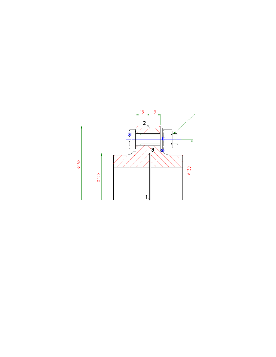
5
For the outer radius ro, choose the pick button next to the entry field and
respond to the prompts as follows:
Specify first point:
Select the point (1)
Second point:
Select the point (2)
6
For the inner radius ri, choose the pick button next to the entry field and
respond to the prompts as follows:
Specify first point:
Select the point (1)
Second point:
Select the point (3)
Now, you have to specify the loads and moments.
7
Choose Next or the Definition of LOADS icon in the top row to proceed.
Using Stand Alone Screw Calculations
|
289
Specifying Loads and Moments
In this section of the screw calculation, you can specify the loads and
moments as well as their points of application.
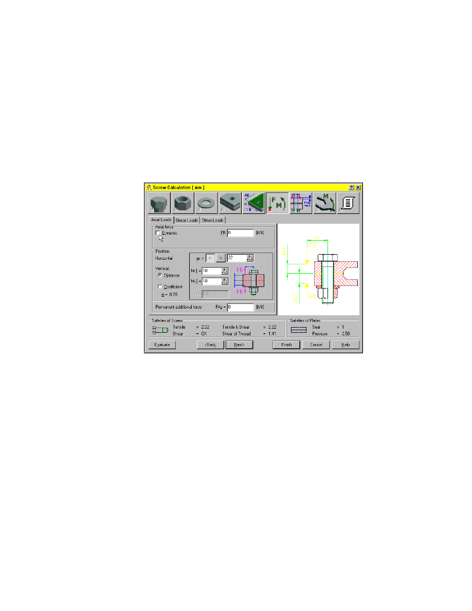
To specify loads and moments
1
On the Axial Loads tab, clear the check box Dynamic and specify:
Force FB:
0
290
|
Chapter 17
Calculating Screw Connections
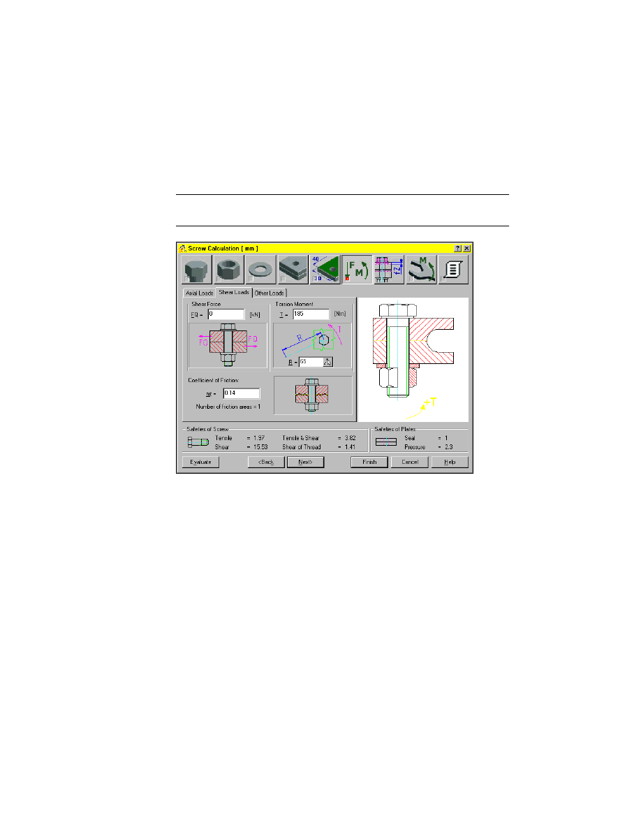
2
Choose the Shear Loads tab and specify:
Torsion Moment T[Nm]:
185
Radius R:
65
Coefficient of Friction mt:
0.14
NOTE
The torsion moment of 185 Nm results from the total torsion moment
of 2405 Nm as given in the terms of reference divided by the 13 bolts.
Now, you have to specify the settlement.
3
Choose Next or the Definition of SETTLEMENT icon in the top row to pro-
ceed.
Using Stand Alone Screw Calculations
|
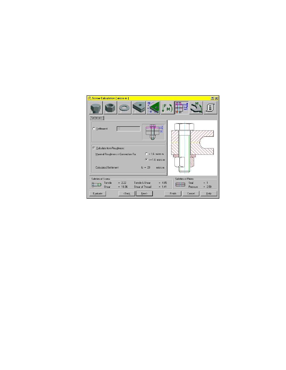
291
Specifying Settlement Properties
In this section of the screw calculation, you can specify settlement properties.
To specify the settlement
1
Activate Calculate from Roughness and
>=
1.6 micro m.
Now, you have to specify the tightening.
2
Choose Next or the Definition of TIGHTEN icon in the top row to proceed.
292
|
Chapter 17
Calculating Screw Connections
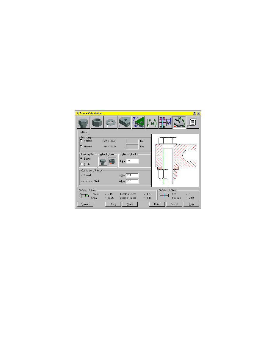
Specifying Tightening Properties
In this section of the screw calculation, you can specify the tightening
method and properties.
To specify the tightening
1
Specify as follows:
Tightening Factor kA:
1.8
Coefficient of Friction in Thread miG:
0.14
Now, you have to insert the result block.
2
Choose Next or the RESULTS icon in the top row to proceed.
Using Stand Alone Screw Calculations
|
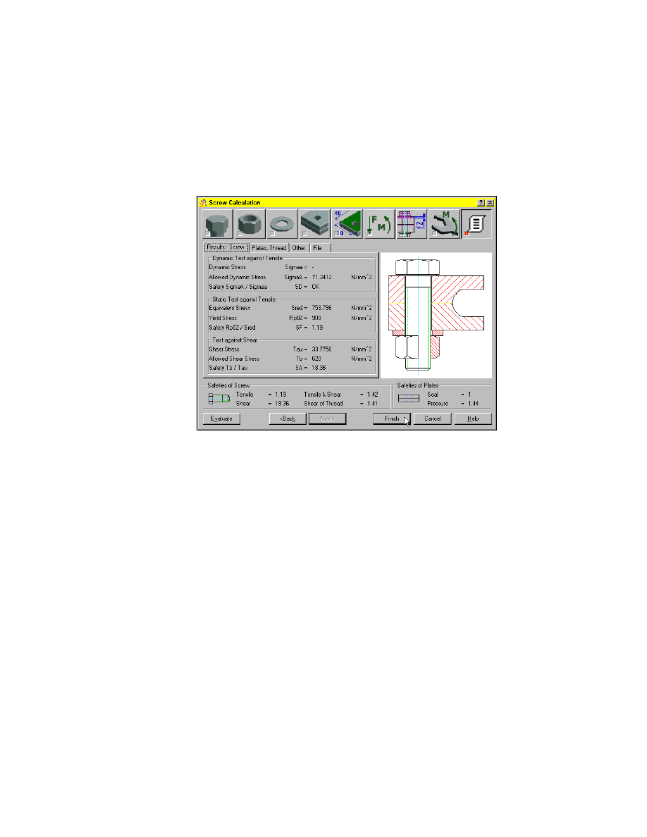
293
Creating and Inserting Result Blocks
In this section of the screw calculation, you can take a look at the results.
You have a complete overview of the results of the screw calculation.
Now, insert the result block.
294
To insert a result block
1
Choose Finish and respond to the prompts as follows:
Specify start point:
Specify a point right of the screw connection
Specify next point <Symbol>:
Press
ENTER
Now, the result block is inserted at the specified location.
This is the end of this tutorial chapter.
Save your file.
Document Outline
- Calculating Screw Connections
Wyszukiwarka
Podobne podstrony:
Ch17 Screw Connections
connections pre intermediate minimock test 0 4 b
Pryda Timber Connectors Catalogue March 2007
ar 156 connect 60360892 05 2004
fiat multipla Nawigator connect nav 60360855 09 2004
Butterworth Finite element analysis of Structural Steelwork Beam to Column Bolted Connections (2)
deer connectdot august5
Screw mechanisms and joints
ar 147 connect nav 60389170 05 2008
connection
4 2 4 5 Packet Tracer Connecting a Wired and Wireless LAN Instructions
Inverter controller for HVDC systems connected to weak AC sy
2 3 2 5 Packet Tracer Implementing?sic Connectivity Instructions
AN Flash Connecting V03
Klein, T E D [SS] Well Connected [v1 0]
Connector List
Connectivity v04
więcej podobnych podstron