CL 74B Winch Motor
Technical manual
EN
CL 74B Winch motor 24 V/wall fitting
Technical manual
DE
CL 74B Stellmotor 24 V/Wandmontage Technisches
Handbuch


Technical manual
3
CL 74B Winch Motor • 99 97
5018
1
PRODUCT DESCRIPTION
4
2
MOUNTING INSTRUCTIONS
5
2.1
Mounting of Winch Motor................................................................................................. 5
3
INSTALLATION INSTRUCTIONS
6
3.1
Electric Installation, Stepless .......................................................................................... 6
3.2
Testing of Electric Installation, Stepless........................................................................ 7
3.3
Electric Installation, On/Off.............................................................................................. 8
3.4
Testing of Electric Installation, On/Off ........................................................................... 8
4
FAULT FINDING
9
5
SPARE PARTS SURVEY
10
6
TECHNICAL DATA CL 74B
11
6.1
Dimensional Sketch (mm) .............................................................................................. 11
6.2
Tensile Length and Tensile Force................................................................................. 12
1
PRODUKTBESCHREIBUNG 13
2
MONTAGEANLEITUNG 14
2.1
Montage des Stellmotors ............................................................................................... 14
3
INSTALLATIONSANLEITUNG 15
3.1
Elektrische Installation, stufenlos................................................................................. 15
3.2
Test der elektrischen Installation, stufenlos................................................................ 16
3.3
Elektrische Installation, on/off....................................................................................... 17
3.4
Test der elektrischen Installation, on/off...................................................................... 17
4
FEHLERSUCHE 18
5
ÜBERSICHT ÜBER ERSATZTEILE
19
6
TECHNISCHE DATEN CL 74B
20
6.1
Maßskizze (mm) .............................................................................................................. 20
6.2
Zuglänge und Zugkraft ................................................................................................... 21
4 Technical
manual
CL 74B Winch Motor • 99 97
5018
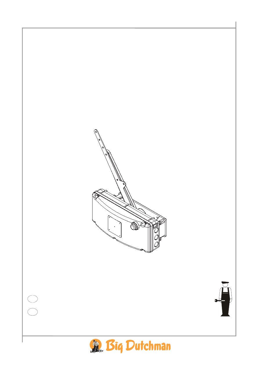
1 PRODUCT DESCRIPTION
CL 74B is a 24 volt winch motor, which is built into a tight plastic cabinet making it suitable for
controlling inlets, windows etc. in a humid environment.
The CL 74B can be mounted on the wall by means of the manufacturer-supplied wall fitting.
The CL 74B can be mounted to either stepless or ON/OFF control as required.
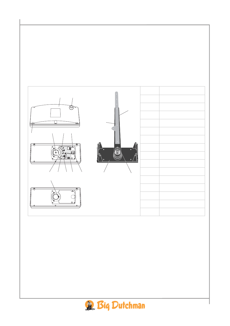
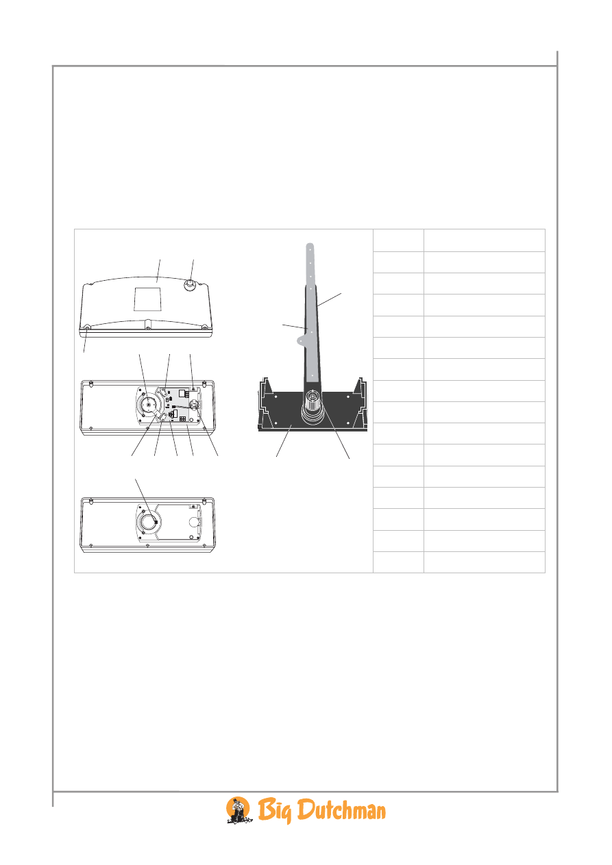
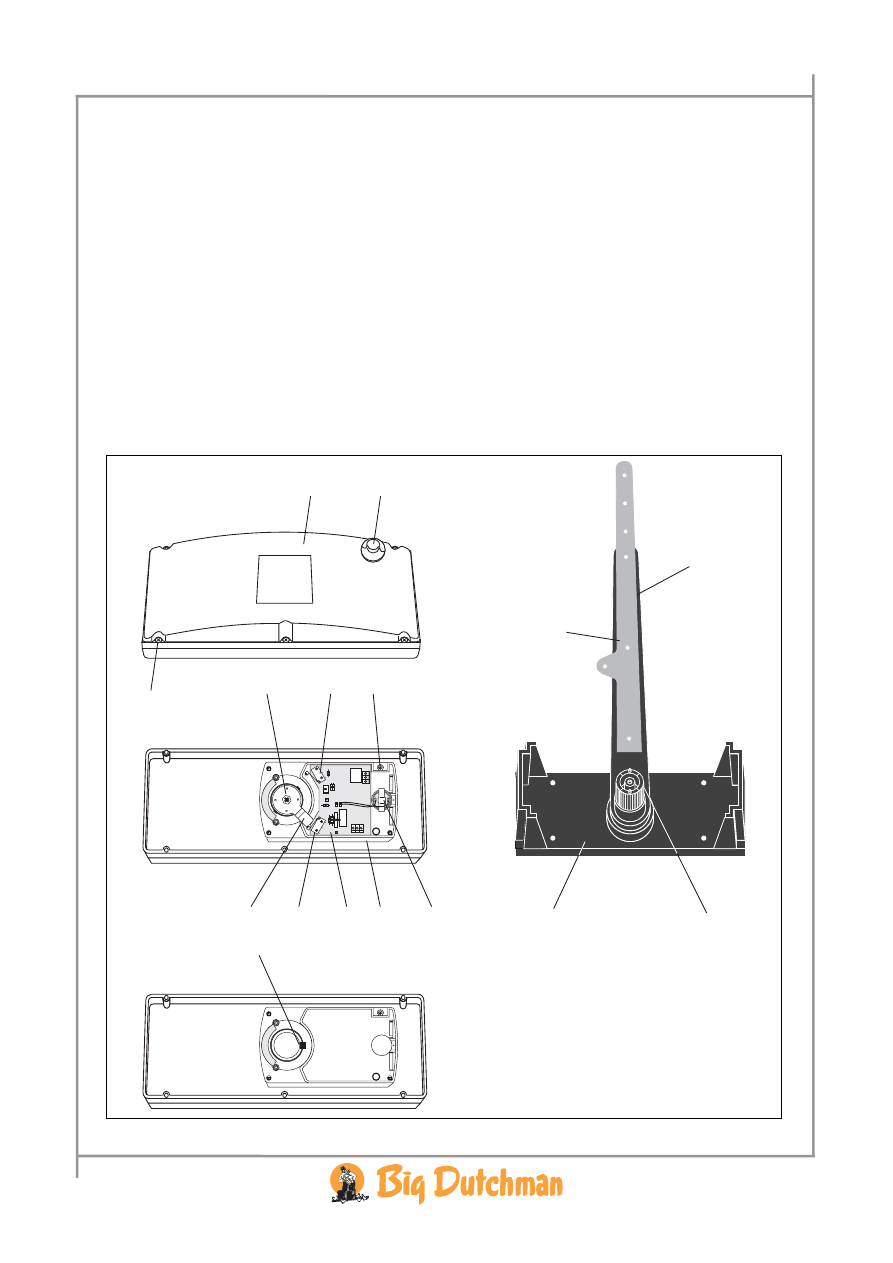
Item Subject
A Arm
B Cover
C Wall
fitting
D
Groove in plastic axle
E
Slot in gear rim
F Cam
disc
G Release
H Limit
switch
I Screw
J Limit
switch
K Complete
gear
unit
L Motor
M
Motor print 24 V
N Screw
SW2
SW1
D2
R7
R4 R5
C1 P2
D3
D4
R1
C2
D1
B
G
N
I
H
G
A
C
D
O
F
J
M K
L
E
O Extension
arm
Technical manual
5
CL 74B Winch Motor • 99 97
5018
2 MOUNTING INSTRUCTIONS
2.1 Mounting of Winch Motor
1 Mount the wall fitting (C) on the wall. Screws and plugs are manufacturer-supplied, but
depending on the quality of the wall they might be insufficient.
2 Turn the arm of the wall fitting (A, O) so that the broad groove (D) of the plastic axle fits into the
slot (E) of the gear rim.
3 Push the winch motor onto the wall fitting (C).
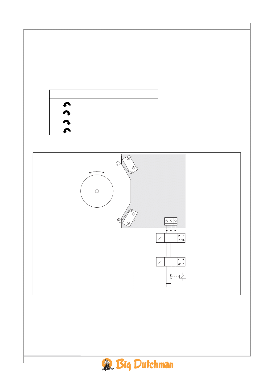
4 Activate the release (G) and turn the arm of the wall fitting (A, O) to centre position.
5 Mount the round cam disc (F) on the two dowels so that the cam turns towards the middle
between the limit switches (H and J).
6 Fasten the screw (I).
Check of limit switches:
1 Activate the release (G) and turn the arm completely clockwise
and check that the limit
switch (J) just gives a small click.
2 Activate the release (G) and turn the arm completely counterclockwise
and check that the
limit switch (H) just gives a small click.
Check of the product, which is to be controlled:
1 Mount the mechanical connection between the winch motor and the product, which is to be
controlled.
2 Check that:
•
The product (inlet, window, door etc.) can open/close completely.
•
The limit switches (H) and (J) just give a small click at completely open and completely
closed.
3 If both limit switches do no give a small click, then readjust the mechanical connection between
the winch motor and the product, which is to be controlled. Check again.
6 Technical
manual
CL 74B Winch Motor • 99 97
5018
3 INSTALLATION INSTRUCTIONS
Note that the electrical connection differs at stepless and ON/OFF control
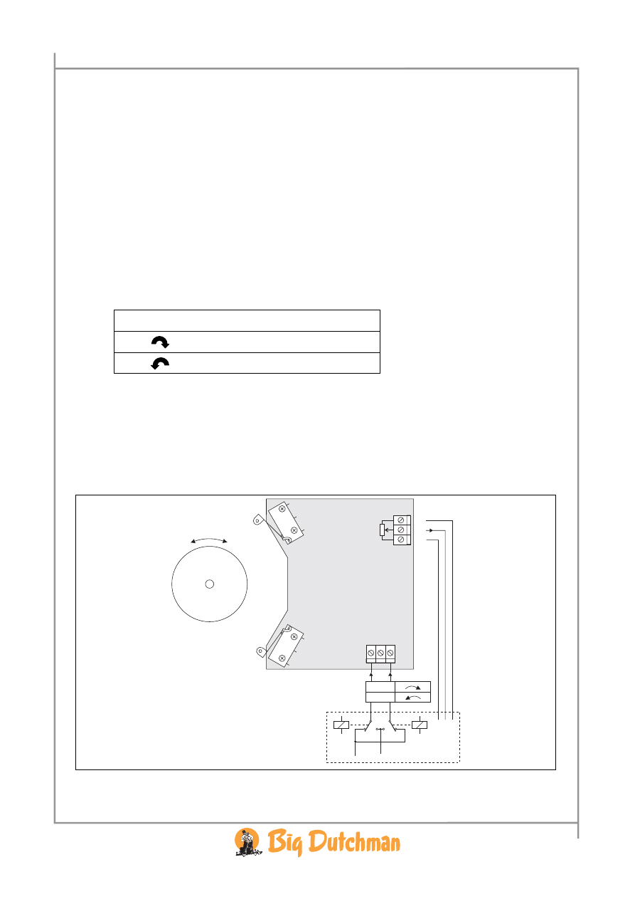
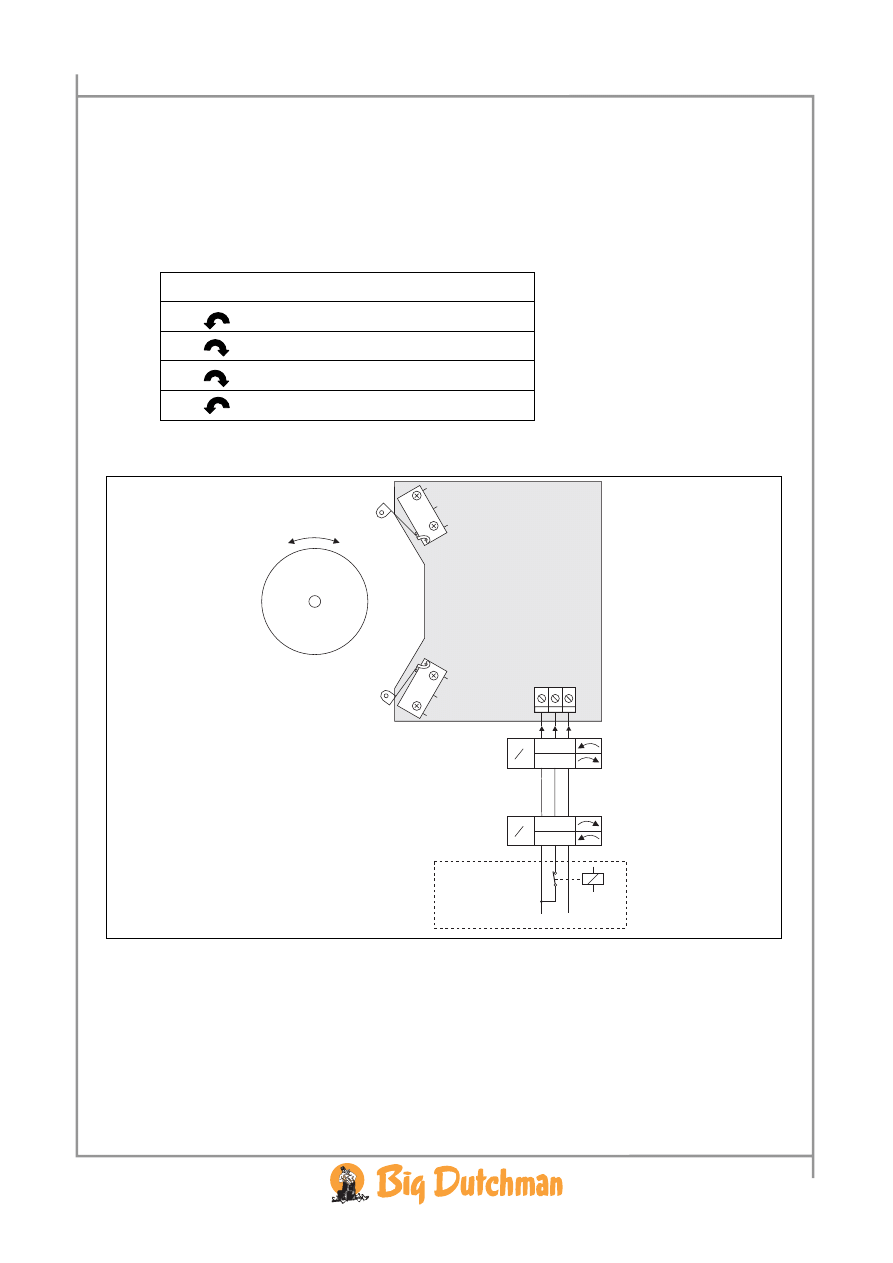
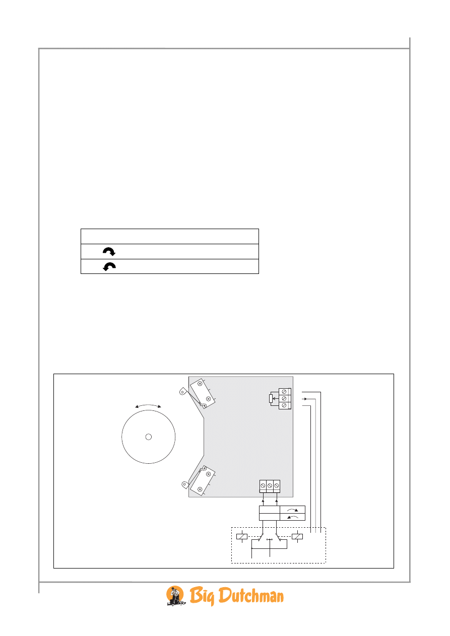
3.1 Electric Installation, Stepless
1. Connect the winch motor to the relevant controller by means of a 5-wire cable.
2. Always lead the cable to the side through a PG 16 screwed flange and possibly downwards to
avoid water penetration.
3. Connect the supply voltage 24 V depending on the required rotating direction.
Rotating direction Terminal 1 Terminal 2 Terminal 3
0 V
NC
+ 24 V
+24 V
NC
0 V
NC = not connected.
4. If a feedback signal to the controller is required, use terminal 6, 7 and 8.
• If for example (+10 V DC) is connected to terminal 6 and (0 V) is connected to terminal 8,
there will be 0 V on terminal 7 in position completely clockwise, approx. 5 V in centre
position and approx. 10 V in position completely counterclockwise.
+
+
_
_
SW2
SW1
1 2 3
67
8
0 V
0-10 V
+10 V
24 V
CL 74B winch motor
Controller

Technical manual
7
CL 74B Winch Motor • 99 97
5018
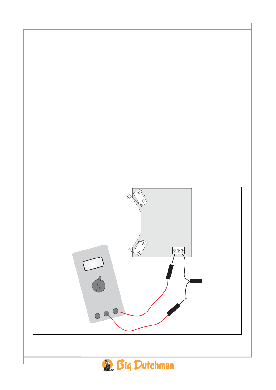
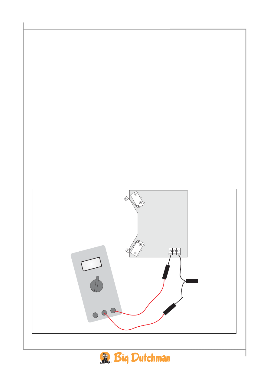
3.2 Testing of Electric Installation, Stepless
With computer control:
1. Carry out a potentiometer calibration/adjustment if this function is in the controller.
If the rotating direction is wrong, interchange the wires in:
• Terminal 1 and 3.
• Possibly terminal 6 and 8 if these are in use.
With other controllers:
1. Let the controller give closing signal:
• Check closed mode, possibly adjust the mechanical connection.
• Check that there is 0 V between terminal 7 and 8.
2. Let the controller give 50 % opening signal:
• Check 50 % open mode.
• Check that there is approx. 5 V between terminal 7 and 8.
3. Let the controller give 100 % opening signal:
• Check open mode, possibly adjust the mechanical connection.
• Check that there is approx. 10 V between terminal 7 and 8.
ERROR:
If the motor does not operate, it may be because terminal 1 and 3 are mixed up.
If the motor does not stop, it may be due to mixed up wires between terminal 6, 8 and possibly 7.
8 Technical
manual
CL 74B Winch Motor • 99 97
5018
3.3 Electric Installation, On/Off
1. Connect the winch motor to the controller with a 3-wire cable.
2. Always lead the cable to the side through a PG 16 screwed flange and possibly
downwards to avoid water penetration.
3. Connect the supply voltage 24 V depending on the required rotating direction.
Rotating direction Terminal 1 Terminal 2 Terminal 3
0 V
0 V
+ 24 V
0 V
NC
+ 24 V
+ 24 V
+ 24 V
0 V
+ 24 V
NC
0 V
NC = not connected
SW2
SW1
1 2 3
ON
OFF
+
+
_
_
ON
OFF
+
+
_
_
+
_
24 V
3.4 Testing of Electric Installation, On/Off
1. Activate the controller so that it gives closing signal.
• Check closed mode, possibly adjust the mechanical connection.
2. Activate the controller so that it gives opening signal.
• Check open mode, possibly adjust the mechanical connection.
CL 74B winch motor
Controller
Technical manual
9
CL 74B Winch Motor • 99 97
5018
4 FAULT FINDING
ERROR: The motor will not operate:
1 Is there 24 V DC between terminal 1 and terminal 3?
1.1
No: There is no control voltage/supply from the controller.
1.2
Yes: Hold the arm (C). Press the release button (G) and turn the arm to centre position.
2 Does the motor run back?
2.1
Yes: Error in the connected controller.
2.2
No: Is there 24 V between the two wires on the motor (L)?
2.2.1
No: Replace the motor print (M).
2.2.2
Yes: Does the motor operate if it is helped by jerking the arm (A)?
2.2.2.1
No: Replace the motor (L).
2.2.2.2
Yes: The load is too heavy or the balancing is wrong. Reduce the
load or correct the balancing.
3 Possibly overload?
3.1
Reduce the load or correct the balancing if the power consumption of the motor is
larger than 0.1 A DC, corresponding to 30 Nm.
SW2
SW1
1 2 3
Amp. D
C

10 Technical
manual
CL 74B Winch Motor • 99 97
5018
5 SPARE PARTS SURVEY
432078
CL 74B winch motor incl. wall fitting 24 V
432954
CL 74B motor print 24 V (M)
432952
CL 74 motor (L)
432959
CL 74 complete gear unit (K)
432054
CL 74 complete wall fitting (C)
SW2
SW1
D2
R7
R4 R5
C1 P2
D3
D4
R1
C2
D1
B
G
N
I
H
G
A
C
D
O
F
J
M K
L
E
Technical manual
11
CL 74B Winch Motor • 99 97
5018
6 TECHNICAL DATA CL 74B
Operating voltage
24 V DC ± 20 % (max. ripple 10 %)
Current consumption max.
0.16 A
Current consumption at 30 Nm
0.10 A
Power consumption max.
4 W
Max. moment
30 Nm
Running time, no load…max. load
110…140 sec.
Feedback potentiometer
10 kΩ
Current consumption in limit switch, stepless
0 A (however, 0.016 A in ON/OFF closed limit switch
Min. service life motor
1000 hours’ running time
Cabinet protection class
IP54
Control signal stepless
2 potential free change-over contacts
Control signal ON/OFF
1 potential free make contact
Screwed flanges
6 pcs. PG16 cable gland knock-outs
Temperature range, operating
-10 °C … +45 °C
Temperature range, storage
-25 °C … +60 °C
Tested for min. 1 mill. activations and 1000 hours’ running time.
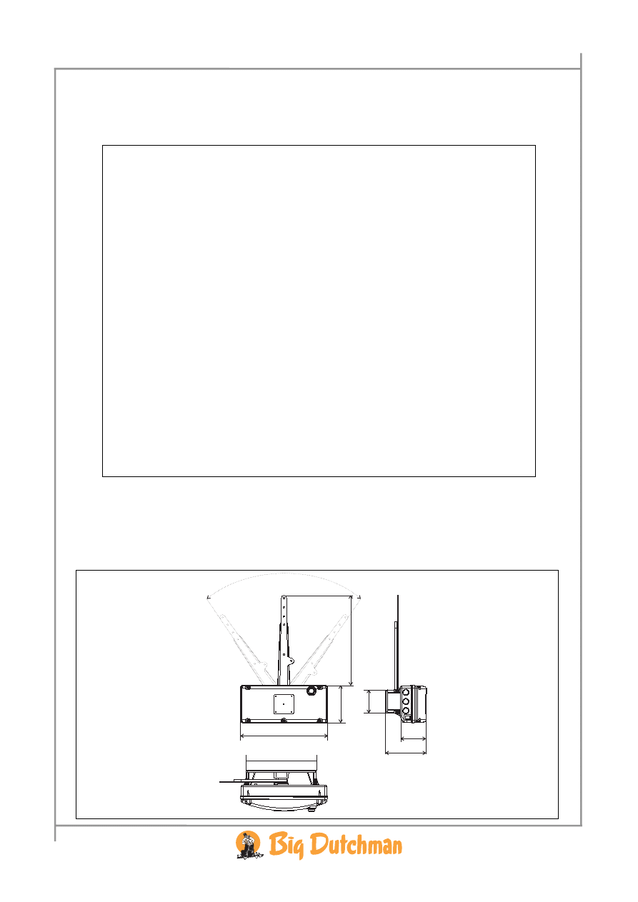
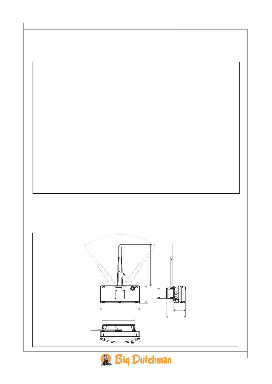
6.1 Dimensional Sketch (mm)
330
142
156
97
338
88
267
12 Technical
manual
CL 74B Winch Motor • 99 97
5018
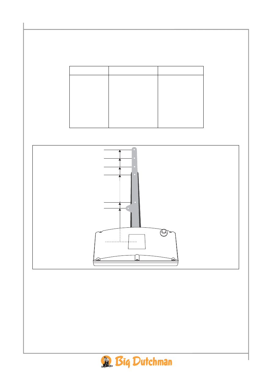
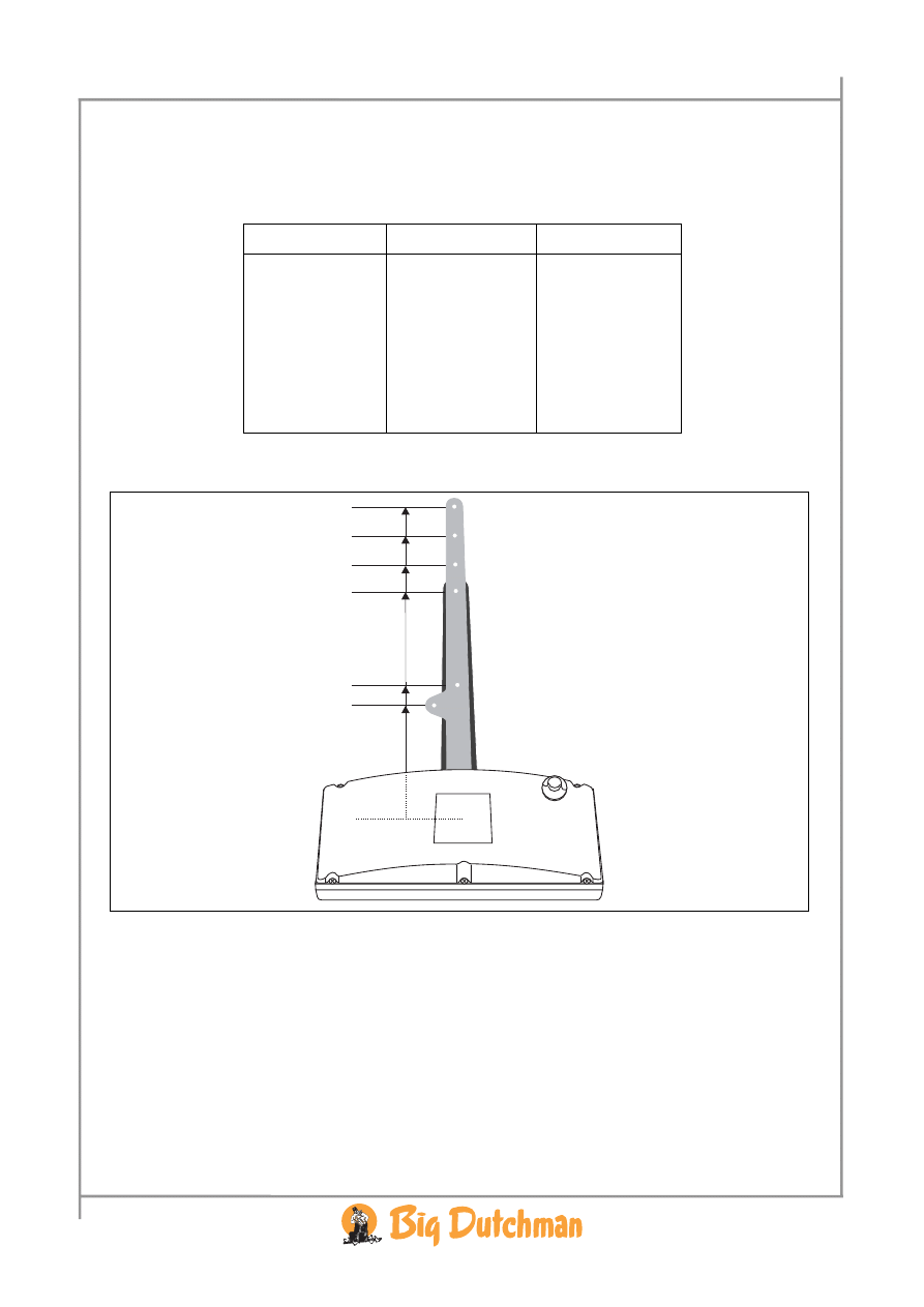
6.2 Tensile Length and Tensile Force
The measurements are made from the centre of the arm of the wall fitting.
Arm length [mm]
Max. tensile force [kg]
Tensile length [mm]
154 19,8 209
176 17,4 251
290 10,5 395
322 9,5 439
357 8,6 483
392 7,8 532
176 mm
322 mm
357 mm
392 mm
290 mm
0
154 mm
Handbuch 13
CL 74B Stellmotor 24 V • 99 97
5018
1 PRODUKTBESCHREIBUNG
Der CL 74B ist ein 24 Volt Stellmotor, der in einem Plastikgehäuse eingebaut ist, und deshalb für
Regelung von Klappen, Fenstern u.a.m. in einer feuchten Umwelt gut geeignet.
Der CL 74B kann mittels des mitgelieferten Wandbeschlags an die Wand montiert werden.
Der CL 74B kann auf Wunsch entweder für stufenlose oder ON/OFF Regelung montiert werden.
Punkt Gegenstand
A Arm
B Deckel
C Wandbeschlag
D
Riefe in Plastikachse
E
Schlitz in Zahnkranz
F Kurvenscheibe
G Auslöser
H Endschutzschalter
I Schraube
J Endschutzschalter
K Komplette
Getriebeeinheit
L Motor
M
Motorplatine 24 V
N Schraube
SW2
SW1
D2
R7
R4 R5
C1 P2
D3
D4
R1
C2
D1
B
G
N
I
H
G
A
C
D
O
F
J
M K
L
E
O Verlängerungsarm
14 Technisches Handbuch
CL 74B Stellmotor 24 V • 99 97
5018
2 MONTAGEANLEITUNG
2.1 Montage des Stellmotors
1. Den Wandbeschlag (C) an die Wand montieren, Schrauben und Dübel liegen bei. Je nach
Beschaffenheit der Wand können diese unzureichend sein.
2. Den Arm des Wandbeschlags (A, O) drehen, so dass die breite Riefe (D) in der Plastikachse
mit dem Schlitz (E) in den Zahnkranz des Motors passt.
3. Den Stellmotor über den Wandbeschlag schieben (C).
4. Den Auslöser (G) aktivieren und den Arm des Wandbeschlags (A, O) zur Mittelstellung
drehen.
5. Die runde Kurvenscheibe (F) auf die beiden Führungszapfen montieren, so dass der Nocken
in die Mitte zwischen den Endschutzschaltern (H und J) zeigt.
6. Die Schraube festschrauben (I).
Kontrolle der Endschutzschalter:
1. Den Auslöser (G) aktivieren und den Arm ganz nach rechts drehen und kontrollieren, ob
vom Endschutzschalter (J) ein leises Klicken zu hören ist.
2. Den Auslöser (G) aktivieren und den Arm ganz nach links drehen und kontrollieren, ob
vom Endschutzschalter (H) ein leises Klicken zu hören ist.
Kontrolle
des Produkts, das geregelt werden soll:
1. Den mechanischen Anschluss zwischen dem Stellmotor und dem Produkt, das geregelt
werden soll, montieren.
2. Kontrollieren, dass:
• Das Produkt (Ventil, Fenster, Tür u.ä.) ganz öffnen/schließen kann.
• Die Endschutzschalter (H) und (J) bei "ganz offen" und "ganz geschlossen" ein
leises Klicken von sich gibt.
3. Wenn beide Endschutzschalter nicht Klicken, muss der mechanische Anschluss
zwischen dem Stellmotor und dem Produkt, das geregelt werden soll, nachgestellt
werden. Danach wird die Kontrolle wiederholt.
Handbuch 15
CL 74B Stellmotor 24 V • 99 97
5018
3 INSTALLATIONSANLEITUNG
Beachten Sie, dass der elektrische Anschluss bei stufenloser und ON/OFF Regelung unterschiedlich
ist.
3.1 Elektrische Installation, stufenlos
1. Den Stellmotor mit einem 5-adrigen Kabel an die aktuelle Steuerung anschließen.
2. Immer das Kabel zur Seite durch eine PG 16 Kabelverschraubung und möglichst nach
unten leiten, um Wassereindringen zu vermeiden.
3. Die 24 V Versorgungsspannung abhängig von der gewünschten Laufrichtung anschließen.
Laufrichtung
Klemme 1 Klemme 2 Klemme 3
0 V
NC
+ 24 V
+24 V
NC
0 V
NC = nicht angeschlossen.
4. Wenn ein Rückführungssignal zur Steuerung gewünscht ist, muss Klemme 6, 7 und 8
verwendet werden.
• Wenn z.B. (+10 V DC) auf Klemme 6 und (0 V) auf Klemme 8 angeschlossen werden,
wird auf Klemme 7 0V sein, wenn man ganz rechts dreht, ca. 5 V in Mittelstellung und
ca. 10 V wenn man ganz links dreht.
+
+
_
_
SW2
SW1
1 2 3
67
8
0 V
0-10 V
+10 V
24 V
Steuerung
CL 74B Stellmotor
16 Technisches Handbuch
CL 74B Stellmotor 24 V • 99 97
5018
3.2 Test der elektrischen Installation, stufenlos
Mit Computersteuerung:
1. Eine Potentiometerkalibrierung/Justierung durchführen, wenn diese Funktion in der Steuerung
enthalten ist.
Wenn die Laufrichtung falsch ist, die Kabel vertauschen in:
• Klemme 1 und 3.
• Evtl. Klemme 6 und 8, wenn diese benutzt werden.
Mit anderen Steuerungen:
1. Die Steuerung ein Schließsignal geben lassen:
• Den geschlossenen Mode kontrollieren und evtl. den mechanischen Anschluss justieren.
• Kontrollieren, dass es zwischen Klemme 7 und 8 0V gibt.
2. Die Steuerung ein 50 % Öffnungssignal geben lassen:
• Den 50 % offenen Mode kontrollieren.
• Kontrollieren, dass es ca. 5 V zwischen Klemme 7 und 8 gibt.
3. Die Steuerung ein 100 % Öffnungssignal geben lassen:
• Den offenen Mode kontrollieren und evtl. den mechanischen Anschluss justieren.
• Kontrollieren, dass es ca. 10 V zwischen Klemme 7 und 8 gibt.
FEHLER:
Wenn der Motor nicht läuft, liegt es vielleicht daran, dass Klemme 1 und 3 vertauscht sind.
Wenn der Motor nicht stoppt, ist es vielleicht auf vertauschte Kabel zwischen Klemme 6, 8 und
vielleicht 7 zurückzuführen.
Handbuch 17
CL 74B Stellmotor 24 V • 99 97
5018
3.3 Elektrische Installation, on/off
1. Den Stellmotor mit einem 3-adrigen Kabel an die Steuerung anschließen.
2. Immer das Kabel zur Seite durch eine PG 16 Kabelverschraubung und möglichst nach
unten leiten, um Wassereindringen zu vermeiden.
3. Die 24 V Versorgungsspannung abhängig von der gewünschten Laufrichtung anschließen
(siehe Abb. 3).
Laufrichtung
Klemme 1 Klemme 2 Klemme 3
0 V
0 V
+ 24 V
0 V
NC
+ 24 V
+ 24 V
+ 24 V
0 V
+ 24 V
NC
0 V
NC = nicht angeschlossen
SW2
SW1
1 2 3
ON
OFF
+
+
_
_
ON
OFF
+
+
_
_
+
_
24 V
3.4 Test der elektrischen Installation, on/off
1. Die Steuerung aktivieren, so dass sie ein Schließsignal gibt.
• Den geschlossenen Mode kontrollieren und evtl. den mechanischen Anschluss justieren.
2. Die Steuerung aktivieren, so dass sie Öffnungssignal gibt.
• Den offenen Mode kontrollieren und evtl. den mechanischen Anschluss justieren.
CL 74B Stellmotor
Steuerung
18 Technisches Handbuch
CL 74B Stellmotor 24 V • 99 97
5018
4 FEHLERSUCHE
FEHLER: Der Motor läuft nicht:
1 Gibt es 24 V DC zwischen Klemme 1 und Klemme 3?
1.1
Nein: Steuerspannung/Versorgung von der Steuerung fehlt.
1.2
Ja: Den Arm (C) festhalten. Den Auslöseknopf (G) eindrücken und den Arm zur
Mittelstellung drehen.
2 Läuft der Motor zurück?
2.1 Ja: Fehler in der angeschlossenen Steuerung.
2.2 Nein: Gibt es 24 V zwischen den beiden Kabeln am Motor (L)?
2.2.1
Nein: Die Motorplatine (M) ersetzen.
2.2.2 Ja: Läuft der Motor, wenn man den Arm (A) mit einem Ruck bewegt?
2.2.2.1
Nein: Den Motor (L) ersetzen.
2.2.2.2
Ja: Die Belastung ist zu groß oder die Symmetrie ist falsch.
Die Belastung reduzieren oder die Symmetrie korrigieren.
3 Eine mögliche Überbelastung?
Die Belastung reduzieren oder die Symmetrie korrigieren, wenn der Stromverbrauch des Motors höher
als 0,1 A DC ist, was 30 Nm entspricht.
SW2
SW1
1 2 3
Amp. D
C
Handbuch 19
CL 74B Stellmotor 24 V • 99 97
5018
5 ÜBERSICHT ÜBER ERSATZTEILE
432078
CL 74B Stellmotor einschl. Wandbeschlag 24 V
432954
CL 74B Motorplatine 24 V (M)
432952
CL 74 Motor (L)
432959
CL 74 komplette Getriebeeinheit (K)
432054 CL 74 kompletter Wandbeschlag (C)
SW2
SW1
D2
R7
R4 R5
C1 P2
D3
D4
R1
C2
D1
B
G
N
I
H
G
A
C
D
O
F
J
M K
L
E
20 Technisches Handbuch
CL 74B Stellmotor 24 V • 99 97
5018
6 TECHNISCHE DATEN CL 74B
Betriebsspannung
24 V-DC +/- 20 % (max. Wellenstrom 10 %)
Stromverbrauch max.
0,16 A
Stromverbrauch bei 30 Nm
0,10 A
Leistungsverbrauch max.
4 W
Max. Moment
30 Nm
Laufzeit, unbelastet…belastet
110 …140 Sek.
Rückstellpotentiometer 10
kΩ
Stromverbrauch beim Endschutzschalter, stufenlos
0 A (aber 0,016 A in ON/OFF geschlossenem Endschutzschalter)
Min. Lebensdauer Motor
1000 Stunden Betriebsdauer
Schutzart IP
54
Steuersignal stufenlos
2 potentialfreie Umschalter
Steuersignal ON/OFF
1 potentialfreier Schließkontakt
Kabelverschraubungen 6
Stck. PG16 Ausschlagsmünzplatten
Temperaturbereich, Betrieb
-10 °C … +45 °C
Temperaturbereich, Lager
-25 °C … +60 °C
Für min. eine Million Aktivierungen und 1000 Stunden Betriebsdauer geprüft.
6.1 Maßskizze (mm)
330
142
156
97
338
88
267
Handbuch 21
CL 74B Stellmotor 24 V • 99 97
5018
6.2 Zuglänge und Zugkraft
Die Maße sind für die Mitte des Arms des Wandbeschlags anzuwenden.
Armlänge [mm]
Max. Zugkraft [kg]
Zuglänge [mm]
154 19,8 209
176 17,4 251
290 10,5 395
322 9,5 439
357 8,6 483
392 7,8 532
176 mm
322 mm
357 mm
392 mm
290 mm
0
154 mm


Big Dutchman International GmbH • Calveslage • Auf der Lage 2 • 49377 Vechta
Rufnr. 04447/801-0 • Fax • 04447/801-237
60
3
78
7 •
03.0
7
.01 •
Code N
r. 99 97-5
0
18
Wyszukiwarka
Podobne podstrony:
Ustawa z dnia 25 06 1999 r o świadcz pien z ubezp społ w razie choroby i macierz
Cwiczenia 23 25 2007
Wykład 25
Wykład12 Sieć z protokołem X 25 i Frame Relay
zwierzaczki 25
25 Wyklad 1 Dlaczego zwiazki sa wazne
wyklad 2012 10 25 (Struktury systemów komputerowych)
Wykład10a Sieć z protokołem X 25 i Frame Relay
prognozowanie i symulacje wyklad (25 str)
25 26
21 25
25 Pilot, Mechanizmy prowadzace do zroznicowania genetycznego miedzy populacjami w obrebie gatunku (
KM W 25 lekkie konst met stud
2 25 Spajanie różnorodnych materiałów
obrazki 25
1996 06 25 1147
25 Prawo Bankowe
więcej podobnych podstron