This article appeared in Printed Circuit Design, a Miller Freeman publication, August, 1998
1998 Miller Freeman, Inc.
1998 UltraCAD Design, Inc.
Just when you thought you had mastered Zo, the charac-
teristic impedance of a PCB trace, along comes a data sheet
that tells you to design for a specific differential impedance.
And to make things tougher, it says things like: “… since the
coupling of two traces can lower the effective impedance, use
50 Ohm design rules to achieve a differential impedance of
approximately 80 Ohms!” Is that confusing or what!!
This article shows you what differential impedance is.
But more than that, it discusses why it is, and shows you how
to make the correct calculations.
Single Trace:
Figure 1(a) illustrates a typical, individual trace. It has a
characteristic impedance, Zo, and carries a current, i. The
voltage along it, at any point, is (from Ohm’s law) V = Zo*i.
General case, trace pair:
Figure 1(b) illustrates a pair of traces. Trace 1 has a
characteristic impedance Z11, which corresponds to Zo,
above, and current i1. Trace 2 is similarly defined. As we
bring Trace 2 closer to Trace 1, current from Trace 2 begins
to couple into Trace 1 with a proportionality constant, k.
Similarly, Trace 1’s current, i1, begins to couple into Trace 2
with the same proportionality constant. The voltage on each
trace, at any point, again from Ohm’s law, is:
V1 = Z11 * i1 + Z11 * k * i2 Eqs. 1
V2 = Z22 * i2 + Z22 * k * i1
Now let’s define Z12 = k*Z11 and Z21 = k*Z22. Then,
Eqs. 1 can be written as:
V1 = Z11 * i1 + Z12 * i2 Eqs. 2
V2 = Z21 * i1 + Z22 * i2
This is the familiar pair of simultaneous equations we
often see in texts. The equations can be generalized into an
arbitrary number of traces, and they can be expressed in a
matrix form that is familiar to many of you.
Special case, differential pair:
Figure 1(c) illustrates a differential pair of traces. Re-
peating Equations 1:
V1 = Z11 * i1 + Z11 * k * i2 Eqs. 1
V2 = Z22 * i2 + Z22 * k * i1
Now, note that in a carefully designed and balanced situ-
ation,
Z11 = Z22 = Zo, and
i2 = -i1
This leads (with a little manipulation) to:
V1 = Zo * i1 * (1-k) Eqs. 3
V2 = -Zo * i1 * (1-k)
Note that V1 = -V2, which we already knew, of course,
since this is a differential pair.
Effective (odd mode) impedance:
The voltage, V1, is referenced with respect to ground.
The effective impedance of Trace 1 (when taken alone this is
called the “odd mode” impedance in the case of differential
pairs, or “single mode” impedance in general) is voltage di-
vided by current, or:
Zodd = V1/i1 = Zo*(1-k)
And since (from above) Zo = Z11 and k = Z12/Z11, this
can be rewritten as:
Zodd = Z11 - Z12
which is a form also seen in many textbooks.
The proper termination of this trace, to prevent reflec-
tions, is with a resister whose value is Zodd. Similarly, the
odd mode impedance of Trace 2 turns out to be the same (in
this special case of a balanced differential pair).
Differential Impedance
What’s the Difference?
Douglas Brooks
Rdiff
Z11
Z22
Zo
i1
i2
i
Z11
Z22
i1 + ki2
i2 + ki1
1
2
2
1
(a)
(b)
(c)
ki2
ki1
Figure 1
Various Trace Configurations

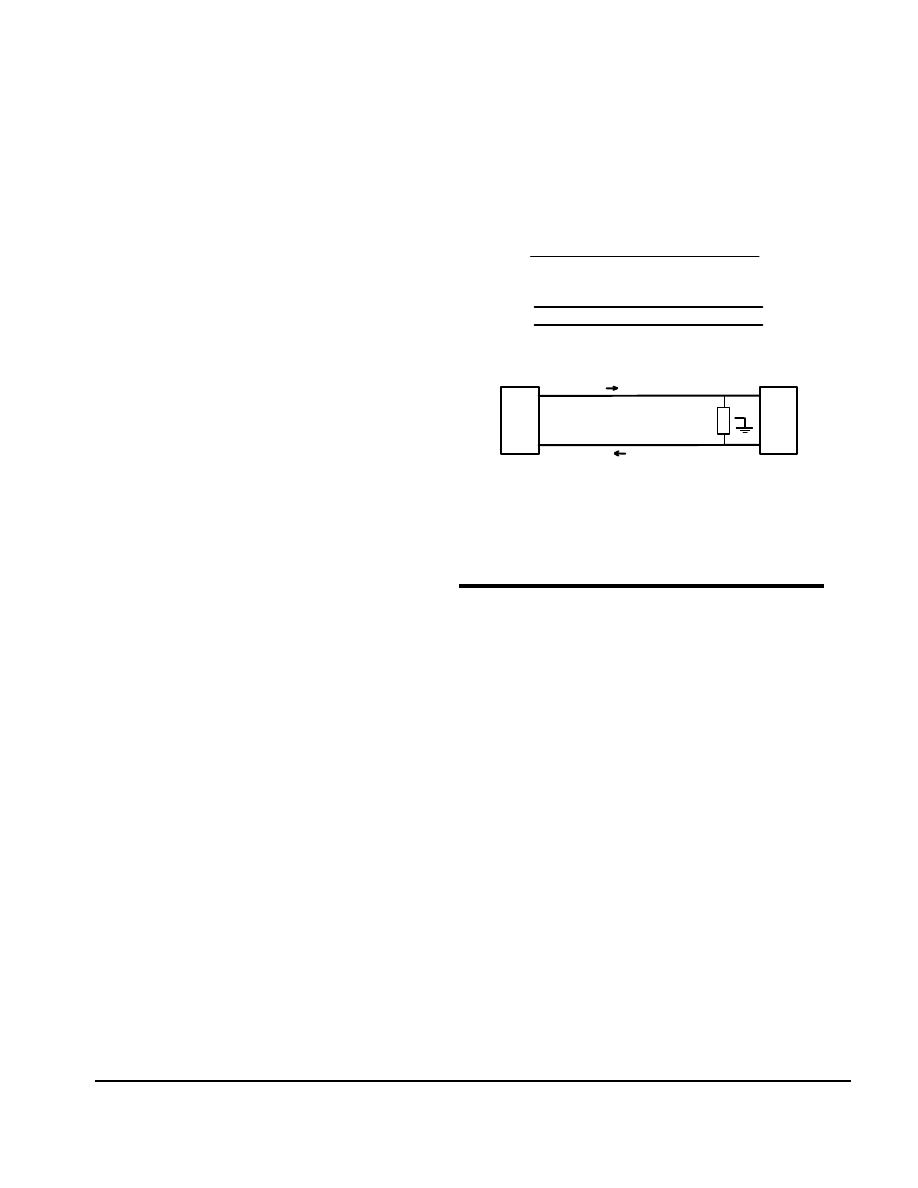
Differential impedance:
Assume for a moment that we have terminated both
traces in a resister to ground. Since i1 = -i2, there would be
no current at all through ground. Therefore, there is no real
reason to connect the resisters to ground. In fact, some peo-
ple would argue that you must not connect them to ground
in order to isolate the differential signal pair from ground
noise. So the normal connection would be as shown in Fig-
ure 1(c), a single resister from Trace 1 to Trace 2. The value
of this resister would be the sum of the odd mode
impedance for Trace 1 and Trace 2, or
Zdiff = 2 * Zo * (1-k) or
2 * (Z11 - Z12)
This is why you often see references to the fact that a
differential pair of traces can have a differential impedance
of around 80 Ohms when each trace, individually, is a 50
Ohm trace.
Calculations:
To say that Zdiff is 2*(Z11 - Z12) isn’t very helpful
when the value of Z12 is unintuitive. But when we see that
Z12 is related to k, the coupling coefficient, things can be-
come more clear. In fact, this coupling coefficient is the
same coupling coefficient I talked about in my Brookspeak
column on crosstalk (Footnote 1). National Semiconductor
has published formulas for Zdiff that have become accepted
by many (Footnote 2):
Zdiff = 2*Zo[1-.48*exp(-.96*S/H)] (Microstrip)
Zdiff = 2*Zo[1-.347*exp(-2.9*S/H)] (Stripline)
where the terms are as defined in Figure 2 and “exp()”
means e, the base of the natural logarithm, raised to the
power in the parentheses. Zo is as traditionally defined
(Footnote 3).
Common Mode Impedance:
Just to round out the discussion, common mode
impedance differs only slightly from the above. The first
difference is that i1 = i2 (without the minus sign.) Thus Eqs.
3 become
V1 = Zo * i1 * (1+k) Eqs. 4
V2 = Zo * i1 * (1+k)
and V1 = V2, as expected. The individual trace impedance,
therefore, is Zo*(1+k). In a common mode case, both trace
terminating resisters are connected to ground, so the current
through ground is i1+i2 and the two resisters appear (to the
device) in parallel. Therefore, the common mode impedance
is the parallel combination of these resisters, or
Zcommon = (1/2)*Zo*(1+k), or
Zcommon = (1/2)*(Z11 + Z12)
Note, therefore, that the common mode impedance is ap-
proximately ¼ the differential mode impedance for trace
pairs.
Microstrip Stripline
Figure 2
Definition of terms for Differential impedance calculations
Footnotes:
1. “Crosstalk, Part 2: How Loud Is It?” Brookspeak, De-
cember, 1997.
2. See National Semiconductor’s “Introduction to LVDS”
(page 28-29) available from their web site at
www.national.com/appinfo/lvds/
or their “Transmission Line RAPIDESIGNER Operation
and Applications Guide”, Application Note 905.
1. See “PCB Impedance Control, Formulas and Re-
sources”, Printed Circuit Design, March, 1998, p12. The
formulas are:
Zo=87*Ln[5.98H/(.8W+T)]/SQR(
ε
r+1.41) (Microstrip)
Zo=60*Ln[1.9(H)/(.8W+T)]/SQR(
ε
r) (Stripline)
h
W
S
W
W
W
S
Wyszukiwarka
Podobne podstrony:
Impedance Terminations, What's the Value
What The United States?n Learn From Japan
wHAT´S THE WEATHER LIKE
what's the time
WHAT THE BLEEP DO WE KNOW
What The Hell
what's the time2
What the wonderful world
What the U S can learn from Polish educational system
Lust s What The Doctor Ordered
what s the weather like B&W
WHAT s the time
What s the matter tiger kl III
konspekt what s the time
What the EPA Don t Know Won t H Suzette Haden Elgin
eReport WINE 101 What the Heck Does Oaky Mean
What the fitter
więcej podobnych podstron