ORDER NO. MD9707082C2
Receiver
AV Control Stereo Receiver
Colour
(K) . . . . . . . . Black Type
SA-EX310
© 1997 Matsushita Electronics (S) Pte. Ltd.
All rights reserved. Unauthorized copying and
distribution is a violation of law.
Area
®
Manufactured under license from Dolby Laboratories Licensing Corporation. Additionally licensed
under one or more of the following patents: U.S. numbers 3,632,886,3,746,792 and 3,959,590;
Canadian numbers 1,004,603 and 1,037,877.
"Dolby" and the double-D symbol are trade marks of Dolby Laboratories Licensing Corporation.
*
Colour
Area
Suffix for
Model No.
(E)
Europe
(EB)
Great Britain
(EG)
Germany and Italy
(K)
SPECIFICATIONS\
ÒÅÕÍÈ×ÅÑÊÈÅ ÕÀÐÀÊÒÅÐÈÑÒÈÊÈ
PROTECTION CIRCUITRY\
ÑÈÑÒÅÌÀ ÇÀÙÈÒÛ
CAUTION FOR AC MAIN LEADS\
ÌÅÐÛ ÁÅÇÎÏÀÑÍÎÑÒÈ ÏÐÈ ÐÀÁÎÒÅ ÑÎ ØÍÓÐÎÌ
ÏÈÒÀÍÈß ÏÅÐÅÌÅÍÍÎÃÎ ÒÎÊÀ
OPERATION CHECKS AND MAIN COMPONENT REPLACEMENT
PROCEDURES\
ÏÐÎÂÅÐÊÀ ÐÀÁÎÒÎÑÏÎÑÎÁÍÎÑÒÈ È ÇÀÌÅÍÀ ÎÑÍÎÂÍÛÕ
ÊÎÌÏÎÍÅÍÒÎÂ
FAN MOTOR TROUBLESHOOTING\
ÍÅÈÑÏÐÀÂÍÎÑÒÈ ÄÂÈÃÀÒÅËß ÎÕËÀÆÄÅÍÈß
TROUBLESHOOTING\
ÍÅÈÑÏÐÀÂÍÎÑÒÈ È ÌÅÒÎÄÛ ÈÕ ÓÑÒÐÀÍÅÍÈß
BLOCK DIAGRAM\
ÁËÎÊ-ÑÕÅÌÀ
TERMINAL FUNCTIONS OF IC's\
ÔÓÍÊÖÈÎÍÀËÜÍÎÅ ÍÀÇÍÀ×ÅÍÈÅ ÂÛÂÎÄÎÂ
ÈÍÒÅÃÐÀËÜÍÛÕ ÌÈÊÐÎÑÕÅÌ
TERMINAL GUIDE OF IC's, TRANSISTORS & DIODES\
ÖÎÊÎËÅÂÊÀ ÂÛÂÎÄÎÂ
ÈÍÒÅÃÐÀËÜÍÛÕ ÌÈÊÐÎÑÕÅÌ, ÒÐÀÍÇÈÑÒÎÐÎÂ È ÄÈÎÄÎÂ
SCHEMATIC DIAGRAMS\
ÏÐÈÍÖÈÏÈÀËÜÍÛÅ ÑÕÅÌÛ
PRINTED CIRCUIT BOARDS\
ÏÅ×ÀÒÍÛÅ ÏËÀÒÛ
WIRING CONNECTION DIAGRAM\
ÑÕÅÌÀ ÑÎÅÄÈÍÅÍÈß
CABINET PARTS LOCATION\
ÐÀÑÏÎËÎÆÅÍÈÅ ×ÀÑÒÅÉ ÊÎÐÏÓÑÀ
REPLACEMENT PARTS LIST\
ÑÏÈÑÎÊ ÇÀÏÀÑÍÛÕ ×ÀÑÒÅÉ
RESISTORS & CAPACITORS\
ÐÅÇÈÑÒÎÐÛ È ÊÎÍÄÅÍÑÀÒÎÐÛ
PACKAGING\
ÓÏÀÊÎÂÊÀ

SA-EX310
Protection Circuitry
The protection circuitry may have operated if either of the follow-
ing conditions are noticed:
No sound is heard when the power is turned on.
Sound stops during a performance.
The function of this circuitry is to prevent circuitry damage if, for
example, the positive and negative speaker connection wires
are "shorted", or if speaker systems with an impedance less than
the indicated rated impedance of the amplifier are used.
If this occurs, follow the procedure outlines below:
1. Turn off the power.
2. Determine the cause of the problem and correct it.
3. Turn on the power once again after one minute.
Note:
When the protection circuitry functions, the unit will not operate
unless the power is first turned off and then on again.
IF rejection ( at 999 kHz )
55 dB
Amplifier Section
Power output (at 240 V)
DIN 1 kHz (T.H.D. 1%)
2 X 60 W(4
Ω
)
40 Hz20 kHz continuous power output
both channels driven
2 X 40 W(8
Ω
)
Total harmonic distortion
Rated power at 40 Hz 20kHz
0.8 % (8
Ω
)
Half power at 1 kHz
0.07 % (8
Ω
)
Power output at the Dolby Pro Logic operation
DIN 1 kHz ( T.H.D. 1 % )
Front
2 X 50 W (4
Ω
)
Center
50 W (8
Ω
)
Surround
50 W (8
Ω
)
Damping factor
30 (8
Ω
)
Load impedance
Front
4 - 16
Ω
Center
8 - 16
Ω
Surround
4 - 16
Ω
Power bandwidth both channels driven, -3 dB 10 Hz - 40 kHz (8
Ω)
Intermodulation distortion rated
power at 60 Hz : 7 kHz = 4:1, SMPTE
0.5 % (8
Ω
)
Frequency response
PHONO
RIAA standard curve(30Hz-15kHz) +0.8 dB
CD, TAPE, VCR, TV/DVD
10Hz 40kHz, +3 dB
Input sensitivity and impedance
PHONO
3 mV / 47 k
Ω
CD, TAPE, VCR, TV/DVD
200 mV / 22 k
Ω
S/N at rated power ( 8
Ω
)
PHONO
70 dB (IHF, A: 80 dB)
CD, TAPE, VCR, TV/DVD
75 dB (IHF, A: 85 dB)
Tone controls
BASS
50 Hz , +10 to -10 dB
TREBLE
20 kHz, +10 to -10 dB
Output voltage
TAPE REC (OUT), VCR OUT
200
mV
Channel balance (250 Hz - 6.3 kHz)
+ 1 dB
Channel separation
55 dB
Headphones output level and impedance
430 mV / 330
Ω
Subwoofer frequency responce
7 100 Hz, + 3 dB
General
Power consumption
160 W
Power supply
E , EG
AC 230 V, 50 Hz
EB
AC 230 - 240 V, 50 Hz
Dimensions (W x H x D)
430 x 136 x 309 mm
Weight
7.3 kg
Notes :
1. Specifications are subject to change without notice.
Weight and dimensions are approximate.
2. Total harmonic distortion is measured by the digital spectrum
Specifications
FM Tuner Section
Frequency range
87.50 108.00 MHz
Sensitivity
S/N 30 dB
1.5
µ
V / 75
Ω
S/N 26 dB
1.3
µ
V / 75
Ω
S/N 20 dB
1.2
µ
V / 75
Ω
IHF usable sensitivity
1.5
µ
V / 75
Ω
(IHF '58)
IHF 46 dB stereo quieting sensitivity
22
µ
V /
75
Ω
Total harmonic distortion
MONO
0.2%
STEREO
0.3%
S/N
MONO
60 dB (75 dB, IHF)
STEREO
58 dB (71 dB, IHF)
Frequency response
20Hz 15 kHz (+1dB, 2dB)
Alternate channel selectivity + 400 kHz
65 dB
Capture ratio
1 dB
Image rejection at 98MHz
40 dB
IF rejection at 98MHz
70 dB
Spurious response rejection at 98MHz
70 dB
AM suppression
50 dB
Stereo separation 1kHz
40 dB
Carrier leak
19kHz
-30 dB (-35 dB, IHF)
38kHz
-50 dB (-55 dB, IHF)
Channel balance (250 Hz - 6.3 kHz )
+1.5 dB
Limitting point
1.2
µ
V
Bandwidth
IF amplifier
180 kHz
FM demodulator
1000 kHz
Antenna terminal(s)
75
Ω
(unbalanced)
Video Section
Output voltage at 1V input (unbalanced)
1±0.1 Vp-p
Maximum input voltage
1.5 Vp-p
Input/output impedance
75
Ω (
unbalanced)
AM Tuner Section
Frequency range AM
( 9 kHz steps )
522 1611 kHz
( 10 kHz steps )
530 1620 kHz
Sensitivty
20
µ
V, 330
µ
V / m
Selectivity ( at 999 kHz )
55 dB
Image rejection ( at 999 kHz )
40 dB
SA-EX310
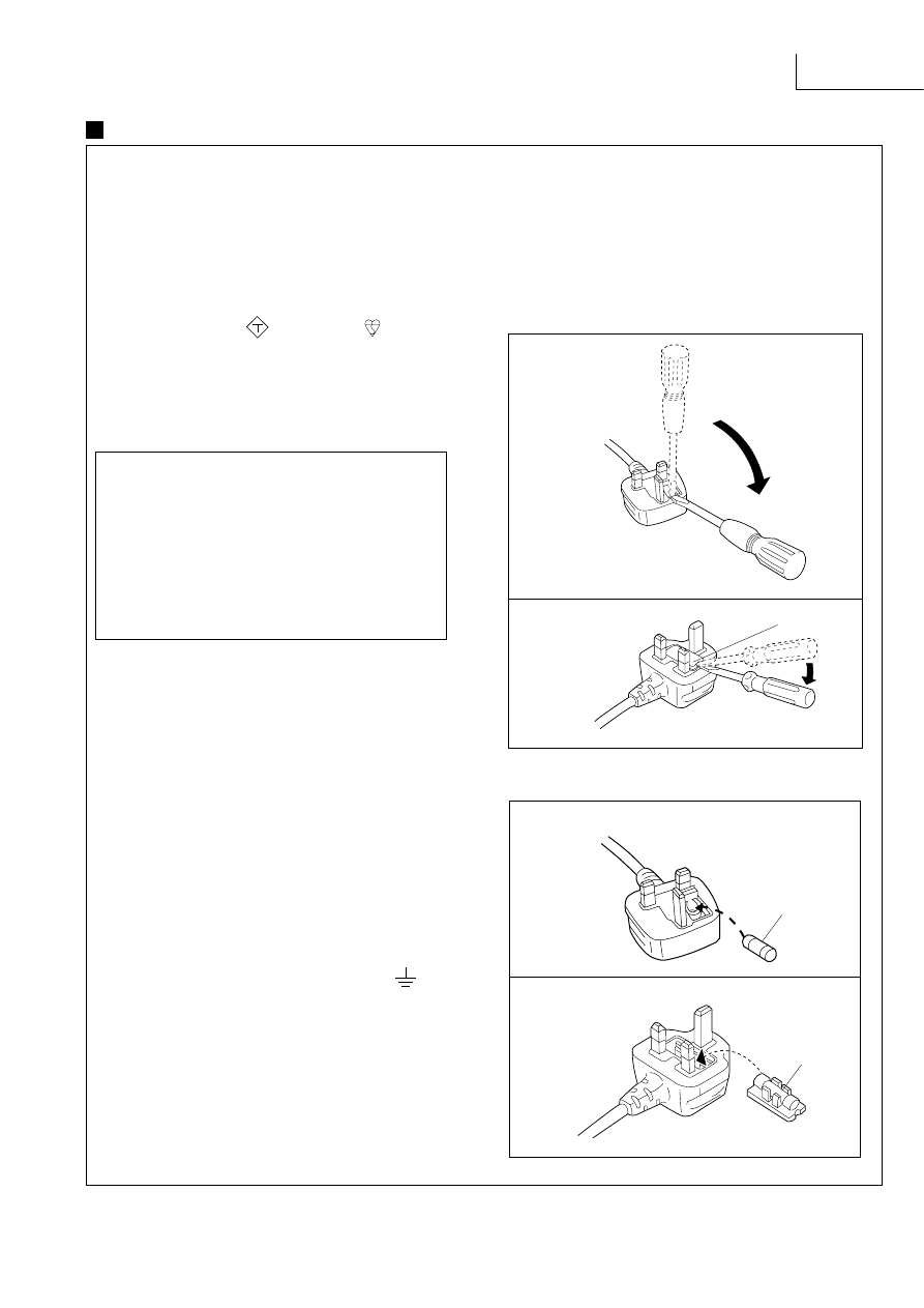
(For EB area code model only.)
For your safety, please read the following text carefully.
This appliance is supplied with a moulded three pin mains plug
for your safety and convenience.
A 5-ampere fuse is fitted in this plug.
Should the fuse need to be replaced please ensure that the
replacement fuse has a rating of 5-ampere and that it is approved
by ASTA or BSI to BS1362.
Check for the ASTA mark
A SA
or the BSI mark
on the body
of the fuse.
If the plug contains a removable fuse cover you must ensure that
it is refitted when the fuse is replaced.
If you lose the fuse cover, the plug must not be used until a
replacement cover is obtained.
A replacement fuse cover can be purchased from your local
dealer.
If a new plug is to be fitted, please observe the wiring code as
shown below.
If in any doubt please consult a qualified electrician.
IMPORTANT
The wires in this mains lead are coloured in accordance with the
following code:
Blue:
Neutral
Brown:
Live
As these colours may not correspond with the coloured markings
identifying the terminals in your plug, proceed as follows:
The wire which is coloured Blue must be connected to the terminal
which is marked with the letter N or coloured Black or Blue.
The wire which is coloured Brown must be connected to the
terminal which is marked with the letter L or coloured Brown or
Red.
WARNING: DO NOT CONNECT EITHER WIRE TO
THE EARTH TERMINAL WHICH IS MARKED WITH
THE LETTER E, BY THE EARTH SYMBOL OR
COLOURED GREEN OR GREEN/YELLOW.
THIS PLUG IS NOT WATERPROOFKEEP DRY.
Before use
Remove the connector cover.
How to replace the fuse
The location of the fuse differ according to the type of AC mains
plug (figures A and B). Confirm the AC mains plug fitted and follow
the instructions below.
Illustrations may differ from actual AC mains plug.
1. Open the fuse cover with a screwdriver.
Figure A
Figure B
2. Replace the fuse and close or attach the fuse
cover.
Figure A
Figure B
CAUTION !
IF THE FITTED MOULDED PLUG IS
UNSUITABLE FOR THE SOCKET OUTLET IN
YOUR HOME THEN THE FUSE SHOULD BE
REMOVED AND THE PLUG CUT OFF AND
DISPOSED OFF SAFELY.
THERE IS A DANGER OF SEVERE
ELECTRICAL SHOCK IF THE CUT OFF PLUG
IS INSERTED INTO ANY 13-AMPERE
SOCKET.
Caution for AC Main Leads
Fuse cover
Fuse
(5 ampere)
Fuse
(5 ampere)
SA-EX310
Operation Checks and Main Component Replacement Procedures
"ATTENTION SERVICER"
Some chassis components may have sharp edges. Be careful when disassembling and servic-
ing. Please take note that the diagrams shown are for model SA-EX510 which is similar to SA-
EX310.
1. This section describes procedures for checking the operation of the major printed circuit boards and
replacing the main components.
2. For reassembly after operation checks or replacement, reverse the respective procedures.
Special reassembly procedures are described only when required.
3. Select items from the following index when checks or replacement are required.
Checking Procedure For Each Major P.C.B ........................................................................................ 4 ~ 6
Main Component Replacement Procedures ........................................................................................ 6 ~ 8
Contents
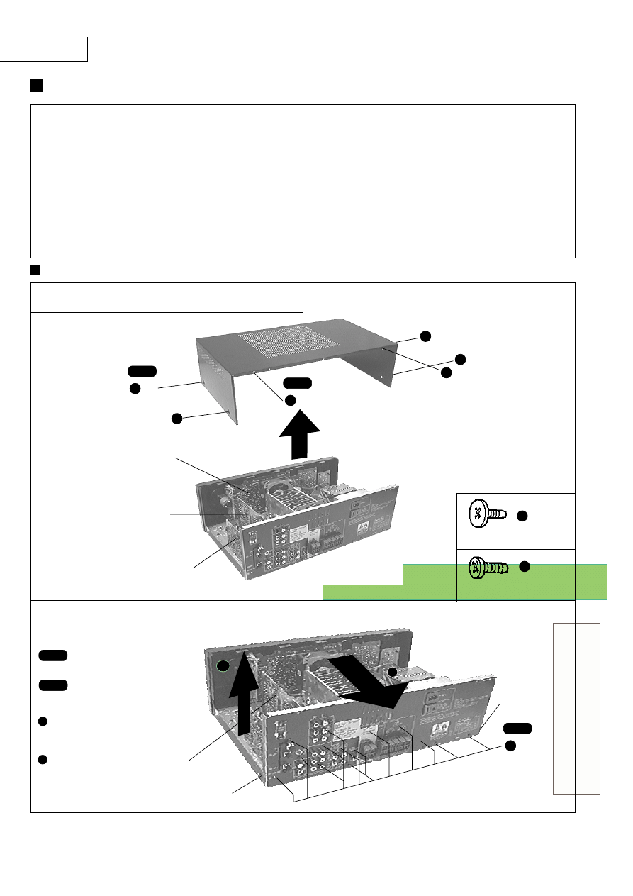
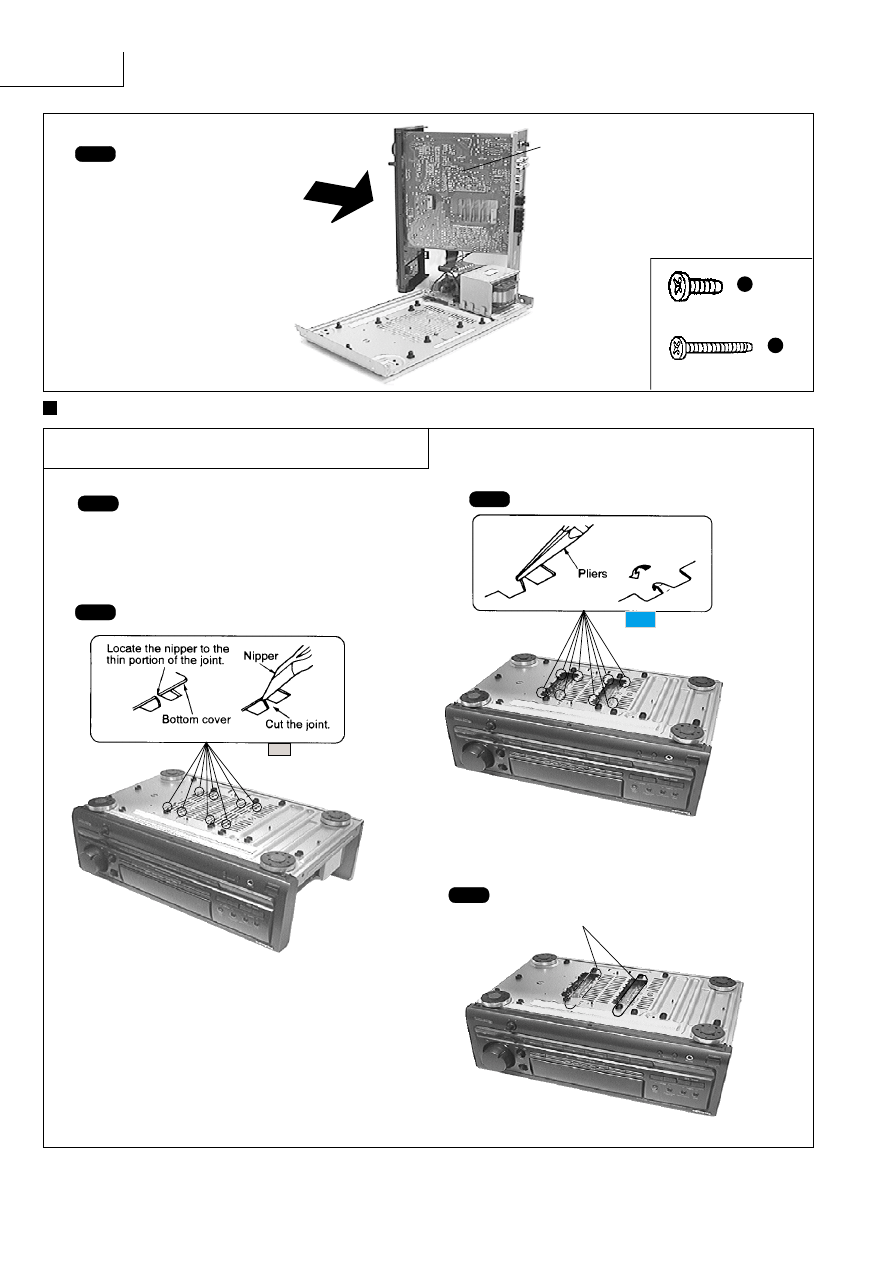
Checking Procedure For Each Major P.C.B.
1. Checking of the Panel P.C.B., and Tuner P.C.B.
a
X
4
a
a
a
b
b
Step 2
X
2
PANEL P.C.B.
(Solder Side)
IN/OUT TERMINAL P.C.B.
(Solder Side)
Step 1
Remove the top cabinet.
TUNER P.C.B.
(Solder Side)
[XTBS3+8JFZ1] (Black)
b
[SNE2129-1] (Black)
a
2. Checking of the In/Out Terminal P.C.B.
b
Step 2
X 14
Step 3
Release the catch, pull
the rear panel in the
direction of arrow
1
and
simultaniously remove the
In/Out Terminal P.C.B. in
the direction of arrow
2
.
1
2
Step 1
Catch
Catch
IN/OUT TERMINAL
P.C.B.
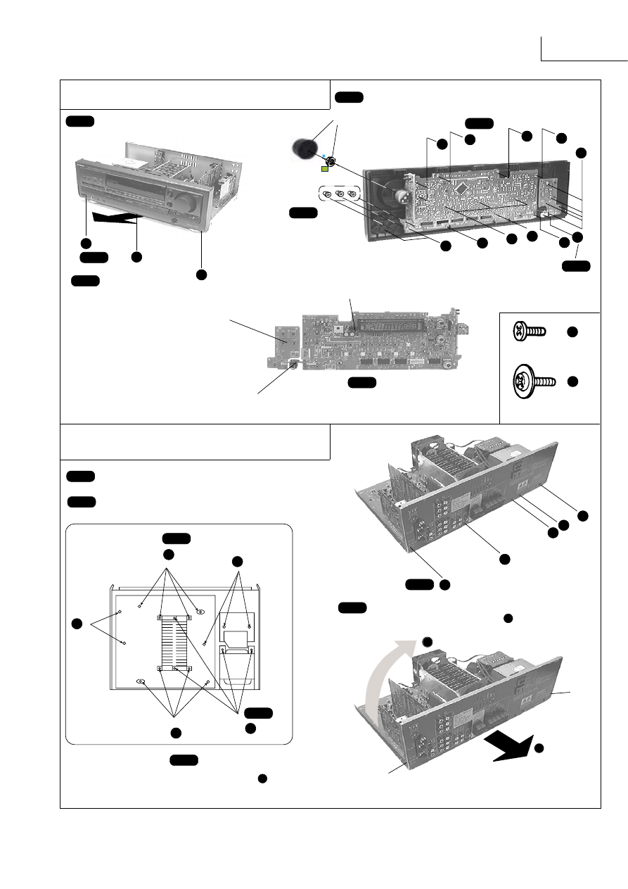
SA-EX310
Step 1
Remove the top cabinet.
c
c
c
c
c
c
c
c
c
c
d
Step 4
Remove the Volume Knob
and Nut.
Step 6
X
18
X 1
Step 7
Step 5
Pull out 3 knobs.
d
[XTBS26+10J]
c
b
b
b
X 3
Step 2
Step 3
Remove the front panel in
the direction of arrow.
Power Switch P.C.B.
Panel P.C.B.
Step 8
Pull out the Headphone
Jack P.C.B.
Headphone Jack P.C.B.
3. Checking of the MAIN P.C.B.
[RHD26016]
f
catch
catch
Step 1
Remove the top cabinet.
Step 2
Remove the front panel.
f
X
13
e
Step 3
b
b
b
b
Step 5
X 4
Step 6
Release 2 catches and pull the rear panel in
the direction of arrow
1
for about 10mm.
(Note : Main, Tuner and In/Out Terminal
P.C.B. are attach to the rear panel)
1
2
Step 7
Lift the rear panel in the direction of arrow
2
.
To Remove Front Panel, Panel P.C.B., Power Switch
P.C.B. and Headphone Jack P.C.B.
f
b
Step 4
X 4
f
SA-EX310
Step 8
Connect the front panel to
the main P.C.B. as shown.
[XTB3+20JFZ] (Black)
f
[XTB3+8FFZ] (Black)
e
MAIN P.C.B. (Solder Side)
Check the Main P.C.B. as shown
Main Component Replacement Procedures
Step 1
Remove the top cabinet.
Step 2
Cut the joints as shown below. (6 joints)
Step 4
Desolder the terminals of Power IC and
Regulator Transistor.
Step 3
Fold the joints. (6 joints)
1. Replacement of the Power IC and
Regulator Transistor
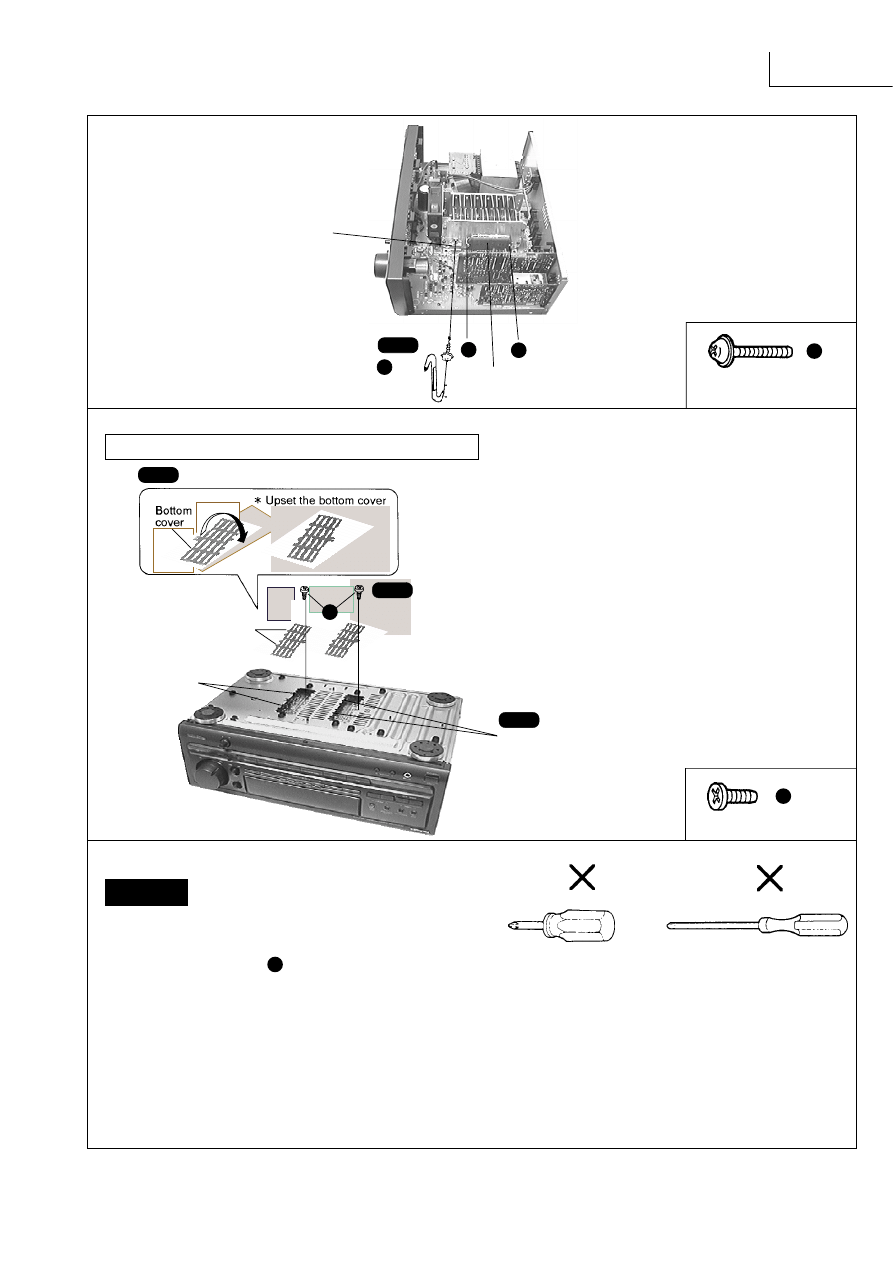
SA-EX310
Installation of the bottom cover after replacement
[XTB3+8J] (Black)
[XTW3+15T]
g
h
Step 1
Step 2
Align the ribs of bottom cover into the lugs.
Step 3
Screw (XTB3+8J)
(Prepare this screw to fix the bottom cover.)
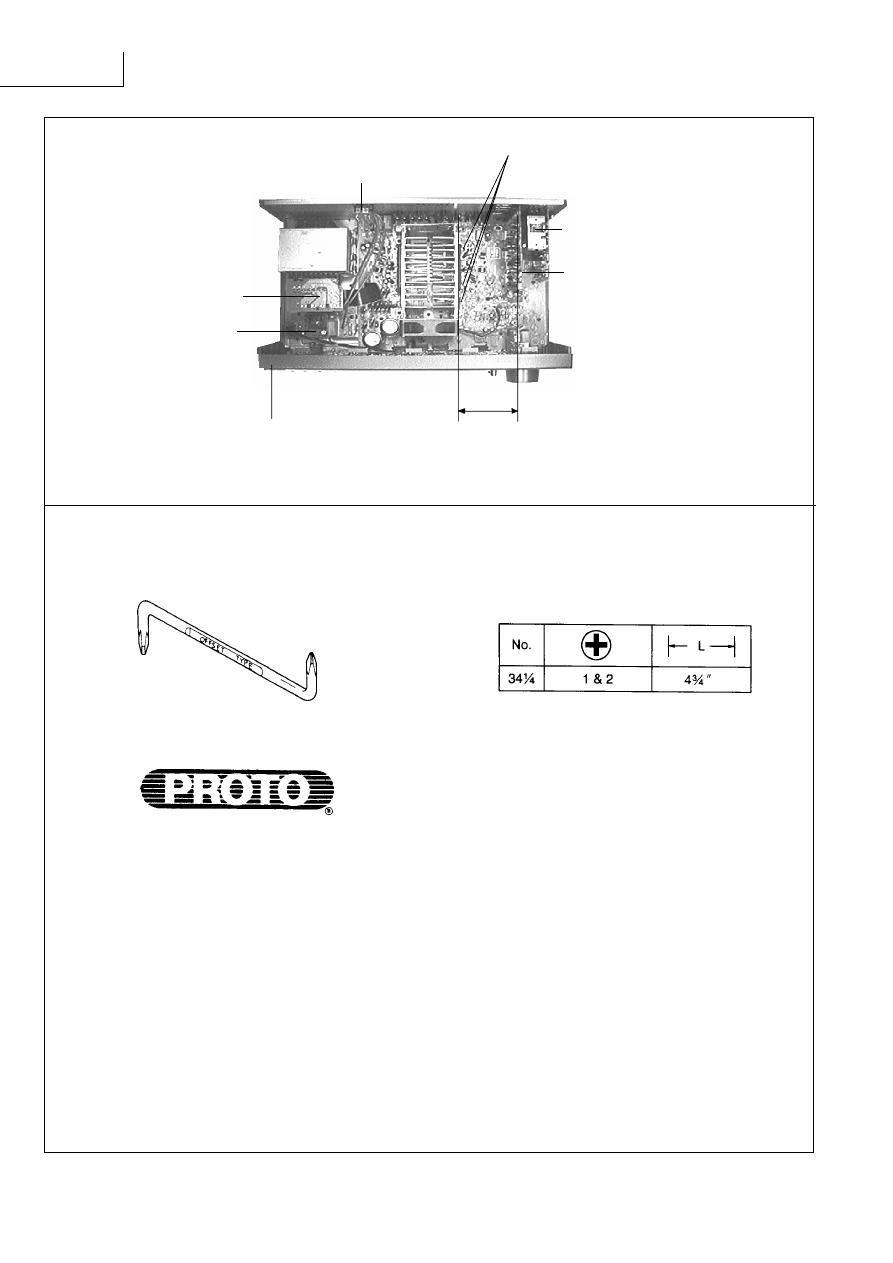
1. After replacing the power IC or regulator transistor, apply a sufficient
quantity of compound grease (RFKX0002/SZZ0L15) between the
heat
sink and the power IC or regulator transistor (Radiation
of power IC).
2. Tighten enough the screws ( ) after replacing the power IC and
regulator transistor. Otherwise, the heat radiation works little.
3. When installing or removing the power IC or transistor holder, be sure
to use an offset screwdriver.
A long straight screwdriver cannot be used for removing or mounting
the screws since its long grip interferes with the neighbouring P.C.B.
and transformer.(See Fig.1 & 3)
A short straight screwdriver may be used for removal, but cannot be
used for mounting because the limited space in the unit will not allow
sufficient tightening torque.(See Fig.2 & 3)
A short straight screwdriver
A long straight screwdriver
Fig.2
Fig.1
Insufficient tightening will cause poor heat dissipation from the power
IC and regulator transistor and,in the worst case, may lead to their
thermal breakdown.
g
X 3
Step 5
g
g
Power IC (IC602)
[RSN3305-P]
g
Regulator transistor
(Q701,Q708)
[2SD2374PQAU,2SB1548PQAU]
*
h
Ribs
Lugs
CAUTION
SA-EX310
OFFSET SCREWDRIVER
The PROTO offset screwdriver No.34-
1
/
4
is recommended for use in the application above.
The address of PROTO International Sales is as follows.
International Sales
International Sales Office
Stanley-Proto Industrial Tools
14117 Industrial Park Blvd.
Covington, GA 30209 U.S.A.
Fax: 706-786-4387
Phone:
706-787-3800
Australia, New Zealand &
South Pacific
Stanley-Proto Industrial Tools
P.O.Box 10
400 Whitehorse Road
Nunrweding 3131
Victoria, Australia
Fax: 61-3-894-1173
Phone:
61-3-878-9244
Singapore, Indonesia,
Philippines, Korea, Hong
Kong, Malaysia, China.
Stanley-Proto Asia Pacific
12 Gul Drive
Singapore 2262
Fax: 65-861-3206
Phone:
65-862-0883
Thailand
Stanley-Proto Thailand Ltd.
1017 Moo 13 Bangkaew
Amphur Bangplee
Samutprakarn, Thailand
Fax: 66-2-316-6071
Phone:
66-2-316-
8655
Japan
Stanley Works Japan
2-7-16 Hyakunin-Cho
Shinjuku-ku
Tokyo 160 Japan
Fax: 81-3-3360-8456
Phone:
81-3-3360-
8458
Mexico
Herramientas Stanley S.A.
DE C.V.
Apartado Postal 675
72030 Puebla, Pue, Maxico
Fax: 52-22-494-4880
Phone:
52-22-495-300
South & Central America,
Puerto Rico, The Caribbian
Stanley Inter-America
2101 N.W. 84th Ave.
Miami, Florida 33122
Fax: 305-594-4261
Phone:
305-591-3828
Europe
Stanley-Proto Europe
Woodside, Sheffield
539PD
England
Fax: 44-742-739-038
Phone:
44-742-768-888
Canada
Stanley-Proto Canada
1100 Corporate Drive
Burlington, Ontorio
Canada, L7L 5R6
Fax: 416-335-0075
Phone:
416-335-0075
Middel East, Mediterranean
& Africa
Stanley-MEMA
Cory House The Rlng
Bracknell Berkshire
RG 12 1A2
England
Fax: 44-344-485-526
Phone:
44-344-51813
Front Panel
About 9 cm
(A long straight screwdriver
connot be used)
Screws
Tuner & Tuner
Pack P.C.B.
Pro Logic
P.C.B.
Fig.3
Power
P.C.B.
Transformer
P.C.B.
AC In / Out
P.C.B.
SA-EX310
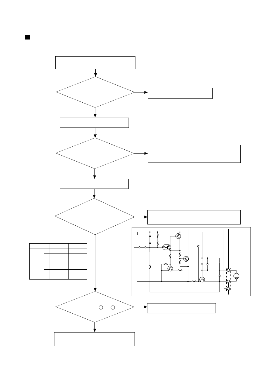
Fan Motor Troubleshooting
Is the air
cooling path blocked
or the fan motorjammed
by any external
obstacle ?
Are the
terminal voltage of
Q772 and Q773 normal in both
and inactive states of the
fan motor ?
(see table1.)
The power IC ( IC601 ) is defective.
The fan motor, power ICs and fan driver
are functioning normally.
YES
Is an audio signal
present at pins 7 and 10
of IC601
NO
YES
NO
Check the integrity of Q772, Q773 and the fan
motor driving circuit. (see Fig.1)
YES
Reinstall the fan on the unit.
Is the fan
motor's DC resistance
20 ~ 30
Ω
?
Fan motor failure
Short circuit : DC resistance below 5
Ω
Open circuit : DC resistance over 1k
Ω
NO
NO
Remove the fan from the unit.
Remove the obstacle.
YES
The Model SA-EX310 employ fan motor error sensing electronics.
If the cooling fan is not operating and "OVER LOAD" is displayed on the FL display, check the fan motor and its driving circuit.
fan. off
fan. on
E
14.5V
14.5V
Q772 C
0V
14.5V
B
14.5V
0V
E
0V
8.5V
Q773 C
14.5V
14.5V
B
0V
8.5V
(Table 1)
(Voltage table)
Fig.1
"OVER LOAD" is displayed on the FL display.
M
Q777
Q776
Q773
C775
0.022
2SB621AQSTA
REGULATOR
R778
R772
4.7K
MTZJ9R1CT
A
D773
CP771
FAN
MOTOR
C773
0.022
R775
R771
+
+
R776
4.7 1/4W
330
Q772
R779
10K
R777 47K
R773
10K
Q778
47K
47K
C772
C771
35V4.7
50V4.7
R774
3.3M
D771 D772
1SS133
Q772,Q776
2SC1740SSTA
MOTOR DRIVE
Q777
2SA933SSTA
MOTOR DRIVE
Q778
RVTDTA114TST
MOTOR DRIVE
D774
1SS133
SA-EX310
REQUIRED ITEMS
1. Testing with a CD player Test disc (SZZP1054C / first progarm, 1kHz, 0dB)
2. Testing with a tape deck Test tape (QZZCLA / 315Hz, 0dB)
3. Testing with a AF oscillator
Set the output at 500Hz, 200mV
4. Oscilloscope (min. 10MHz)
-----------
To measure the output waveform at the test points.
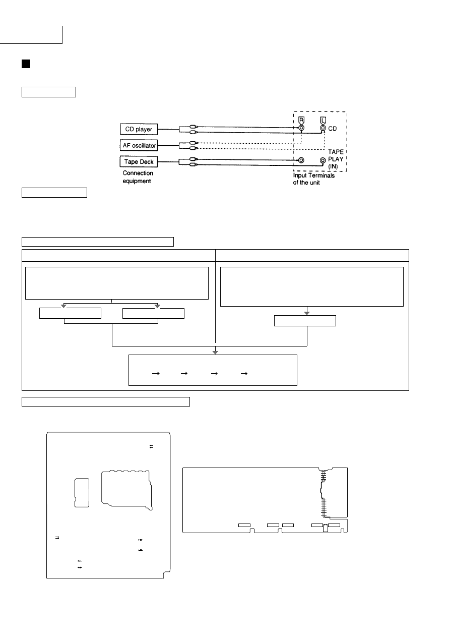
TEST PROCEDURE FOR AMPLIFIER CIRCUIT
When the CD player AF oscillator is connected:
When the tape deck is connected:
Troubleshooting
This unit has test points on each circuit board block for use in troubleshooting.
CONNECTION
Connect either a CD player, tape deck or AF oscillator to the input terminals of the unit.
(
(
)
)
Power on the unit.
Set the input selector button of the unit to the "TAPE MONITOR"
postion.
Set the Speaker ON/OFF button of the unit to the SPEAKERS
"ON" position.
Run the tape deck
QZZCLA
315Hz, 0dB
(
)
Using the Oscilloscope, check the output waveforms at the test
points on the circuit boards of the unit in the following order:
(L1,R1) (L2,R2) (L3,R3) (L5,R5) (L6,R6).
Refer to page 10.
TEST POINTS POSITIONS OF AMPLIFIER CIRCUIT
Note: Connect the '+' probe of
the oscilloscope to each
test point and the ''
probe to chassis ground.
Power on the unit.
Set the input selector button of the unit to the "CD" postion.
Set the Speaker select buttons of the unit to the SPEAKERS "
ON" position.
Run the CD player
or
Run the AF oscillator
SZZP1054C / first program
Oscillator output
1kHz, 0dB
at 500Hz, 200mV
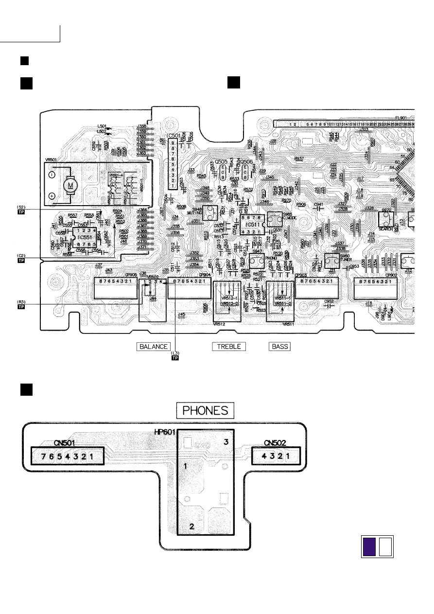
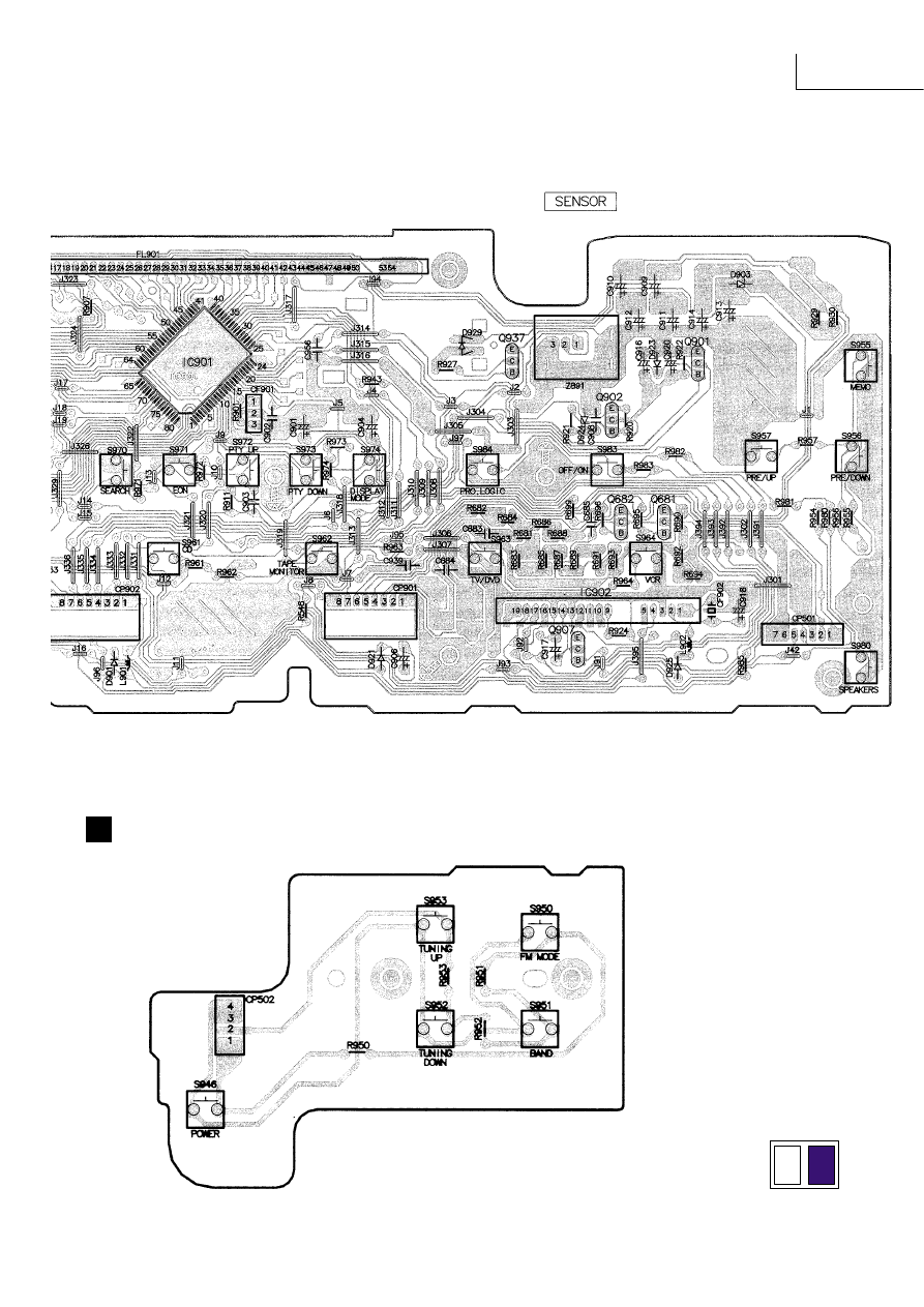
MAIN P.C.B. ( component side )
PANEL P.C.B. ( component side )
R6
L6
R5
L5
L1
R1
+
+
C1001
C1002
J248
J247
J319
J318
L2
C1004
C1067
R2
+
R3
L3
VR502
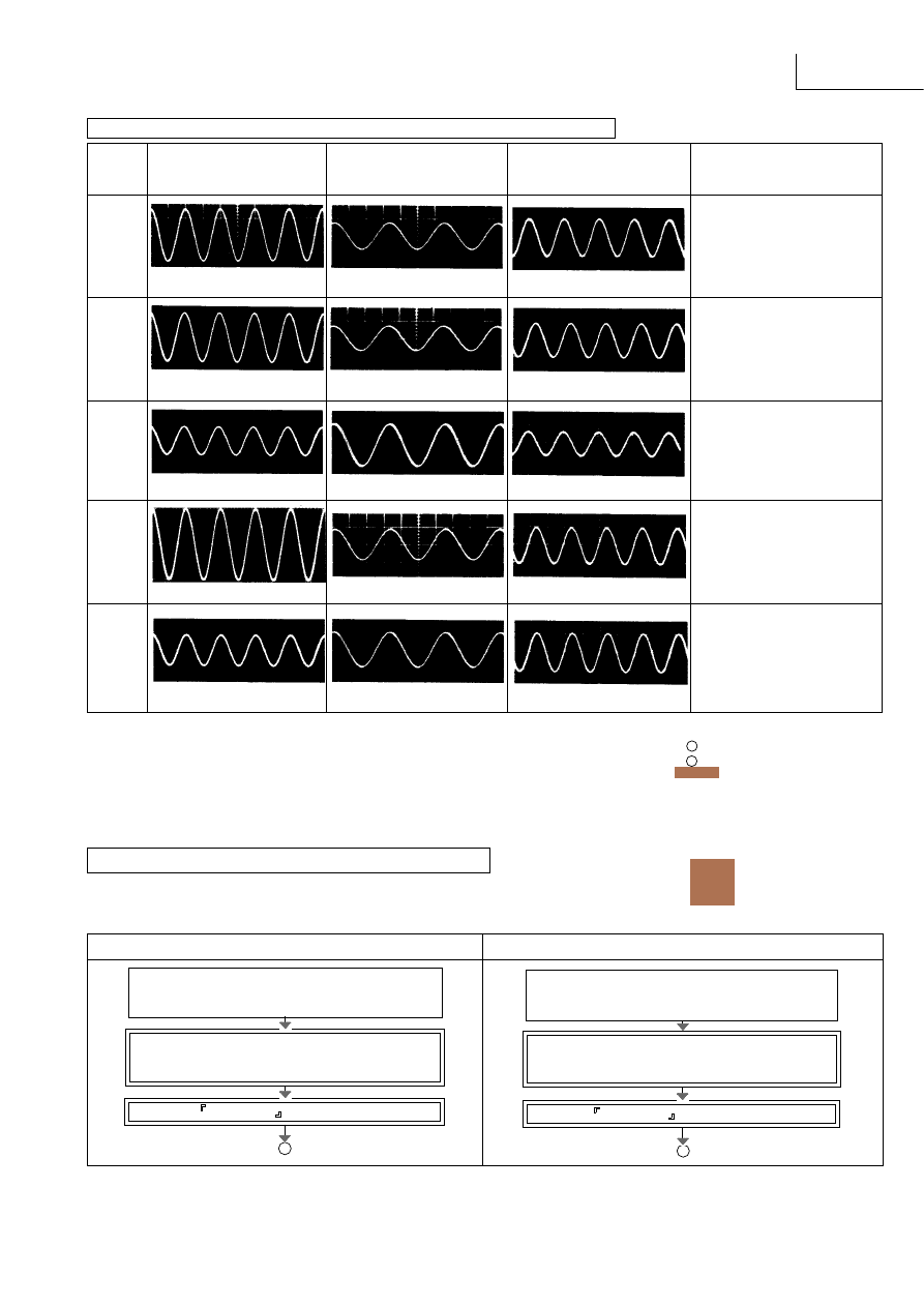
SA-EX310
Likely faulty block if the normal
TP
CD player
Tape deckAF oscillator
waveform shown at the left is not
present.
L1/R1
Input selector block IC402 &
area
0.5msec 2V
1msec 500mV
1msec 500mV
L2/R2
Dolby pro logic blockIC1001 and
IC1002& area
0.5msec 2V
1msec 500mV
1msec 500mV
L3/R3
Master volume block VR501 &
area
0.5msec 500mV
1msec 50mV
1msec 100mV
L5/R5
Power limiter block Q601 to
Q602
& area
0.5msec 100mV*
1msec 500mV
1msec 500mV
L6/R6
Main amplifier block IC601 &
area
0.5msec 5V*
1msec 10V
1msec 10V
NORMAL WAVEFORMS OF AMPLIFIER CIRCUIT AND LIKELY FAULTY BLOCKS
Measurement conditions.
Volume control (VR501), Treble
control (VR512) and Bass control (VR511) positions
:
*Volume control position (VR501) for these test
:
CHECKING PROCEDURE FOR SURROUND CIRCUIT
Outputting surround signal normally requires that opposite phase signals be applied to both the left and right channels.
However, this unit incorporates a service mode, allowing the surround circuit to be tested using in-phase signals.
The letter SURROUND flash on the FL display.
When the CD player or AF oscillator is connected :
When the tape deck is connected :
The letter SURROUND flash on the FL display.
Power on the unit.
Set the input selector button of the unit to the "CD"
position.
Power on the unit.
Set the input selector button of the unit to the "TAPE
MONITOR" position.
A
B
While pressing both "+" and "-" of the surround
level adjustment button "SURROUND, press the
"Power" button.
While pressing both "+" and "-" of the surround
level adjustment button "SURROUND, press the
"Power" button.
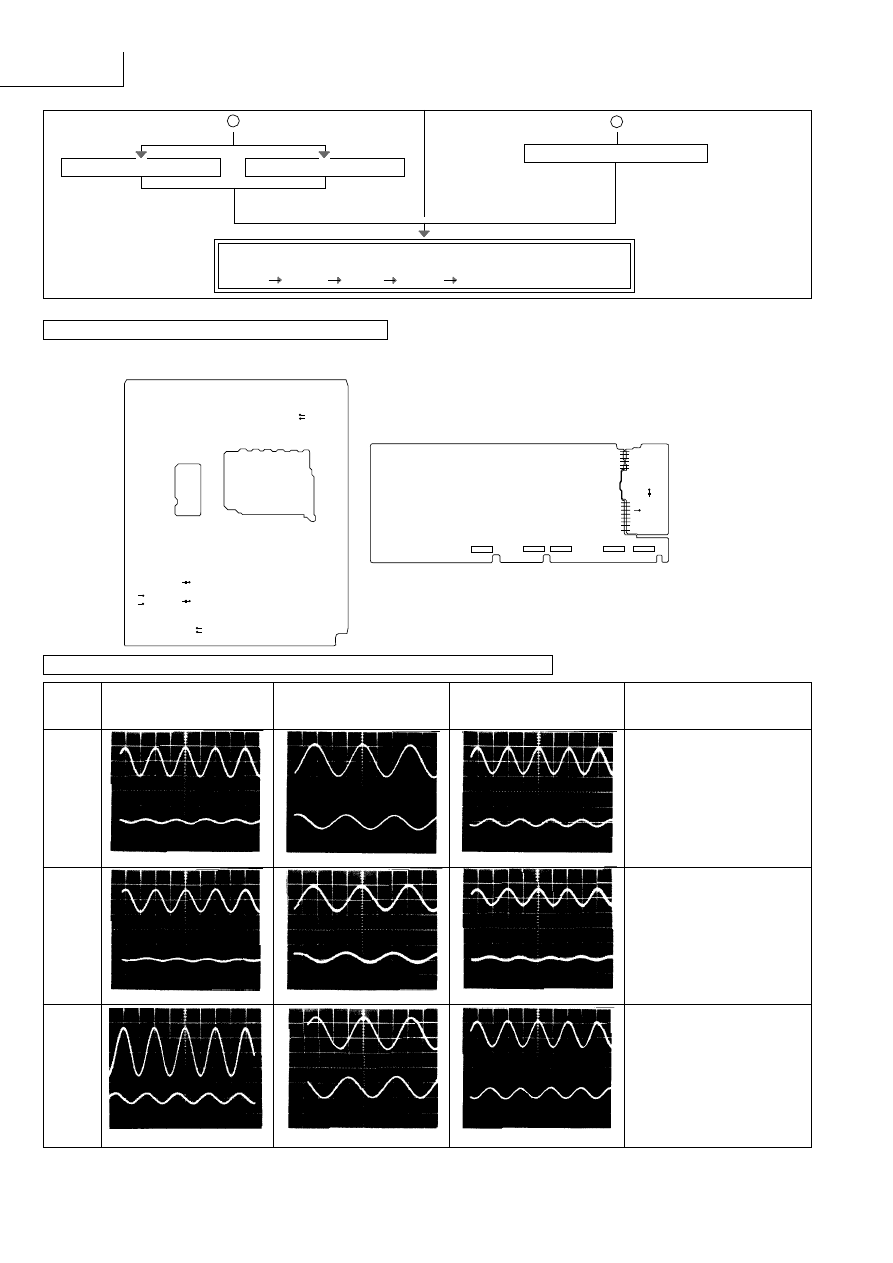
SA-EX310
Likely faulty block if the normal
TP
CD player
Tape deckAF oscillator
waveform shown at the left is not
present.
C1
Dolby pro logic block
IC1001 and IC1002 & area
S1
0.5msec 1V
1msec 100mV
1msec 200mV
C2
Master volume block VR501 &
area
S2
0.5msec 200mV
1msec 20mV
1msec 50mV
C3
Tone control block IC551 & area
S3
0.5msec 200mV*
1msec 500mV
1msec 1V
( )
( )
B
Run the tape deck
Run the AF oscillator
Run the CD player
QZZCLA
315Hz, 0dB
( )
Oscillator output
at 500Hz, 200mV
SZZP1054C/first program
1kHz, 0dB
A
Using the Oscilloscope, check the output waveforms at the test points on
the circuit boards in the following order :
(C1,S1) (C2,S2) (C3,S3) (C4,S4) (C5,S5).
To exit the service mode, power off the unit.
TEST POINTS POSITIONS OF SOURROUND CIRCUIT
NORMAL WAVEFORMS OF AMPLIFIER CIRCUIT AND LIKELY FAULTY BLOCKS
PANEL P.C.B. ( component side )
Note: Connect the '+' probe of
the oscilloscope to each
test point and the ''
probe to chassis ground.
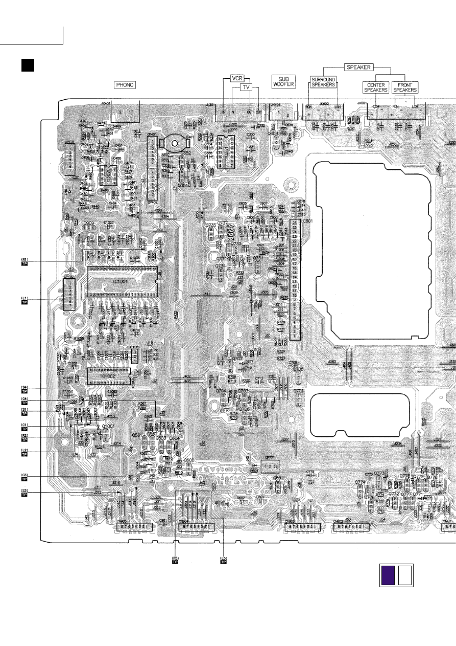
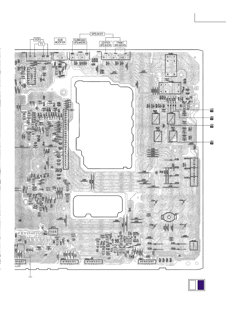
MAIN P.C.B. ( component side )
C1
S1
S3
C3
C4
+
+
C604
C603
J22
J21
J313
J316
S4
C5
S5
J246
J245
S2
+
C551
R552
C2
SA-EX310
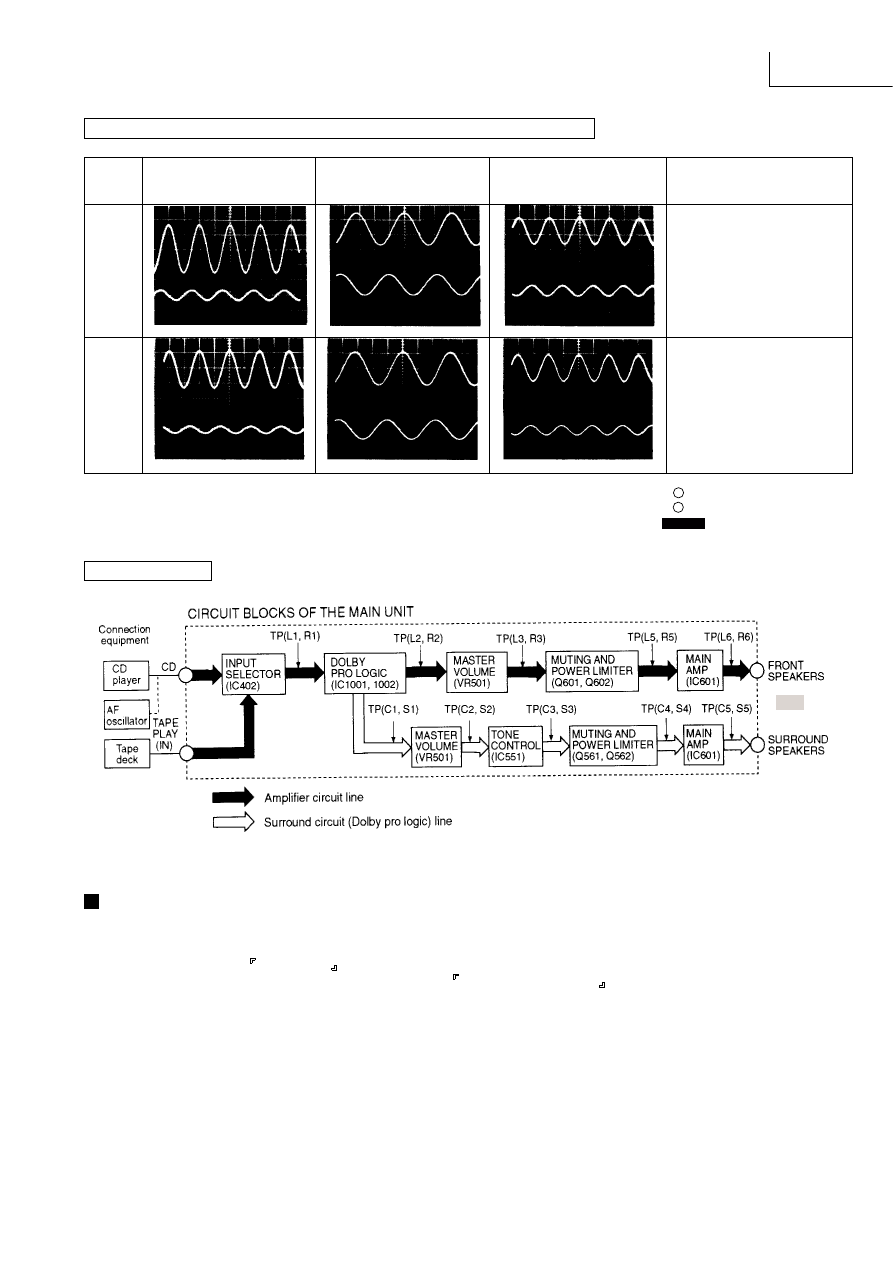
NORMAL WAVEFORMS OF AMPLIFIER CIRCUIT AND LIKELY FAULTY BLOCKS
The HIC protection circuit functions if any cord at a speaker terminal is short-circuited or if the unit overheats because of improper
operation. At the same time, OVERLOAD scrolls across the FL display.
In this state, all keys remain in operative; if any key is pressed, SWITCH OFF POWER scrolls across the FL display.
If an overload occurs, immediately power off the unit and check the speaker connection, venting holes and cooling fans. After
fixing any faults, power on the unit again and check for proper operation.
If no defects are found, or if the unit remains overload after it is power on again, check the circuit for faults.
CIRCUIT BLOCKS
OVERLOAD DETECTION FUNCTION
Likely faulty block if the normal
TP
CD player
Tape deckAF oscillator
waveform shown at the left is not
present.
C4
Power limiter block
Q551 to Q552 & area
S4
0.5msec 200mV*
1msec 500mV
1msec 1V
C5
Main amplifier block IC601 &
area
IC602 & area
S5
0.5msec 5V*
1msec 10V
1msec 1V*
Measurement conditions.
Volume control (VR501), Tremble
control (VR512) and Bass control (VR511) positions
:
*Volume control position (VR501) for these test
:
SA-EX310
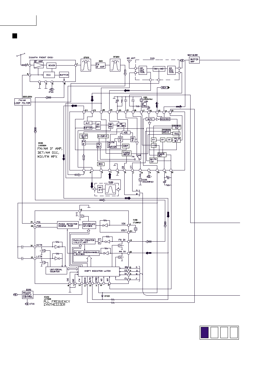
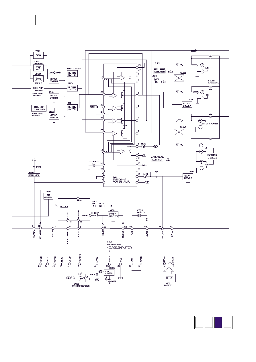
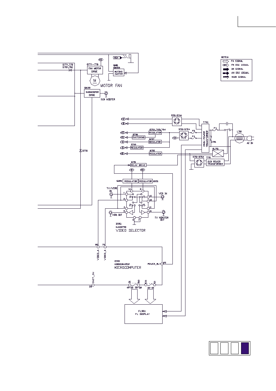
Block Diagram
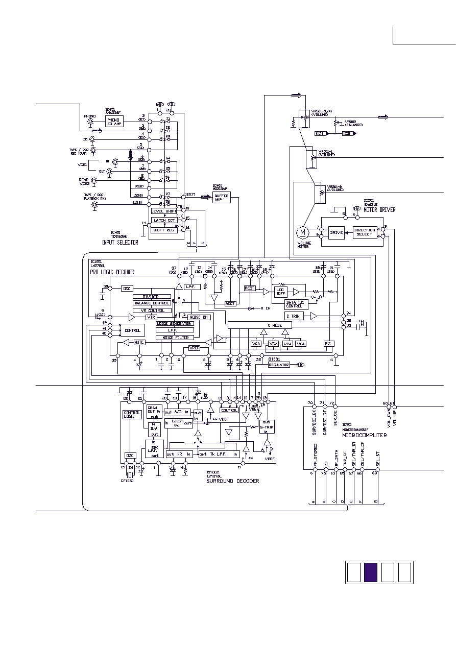
SA-EX310
SA-EX310
SA-EX310
SA-EX310
Terminal Functions Of ICs
IC901 (M38B53M4053F)
System Microprocessor
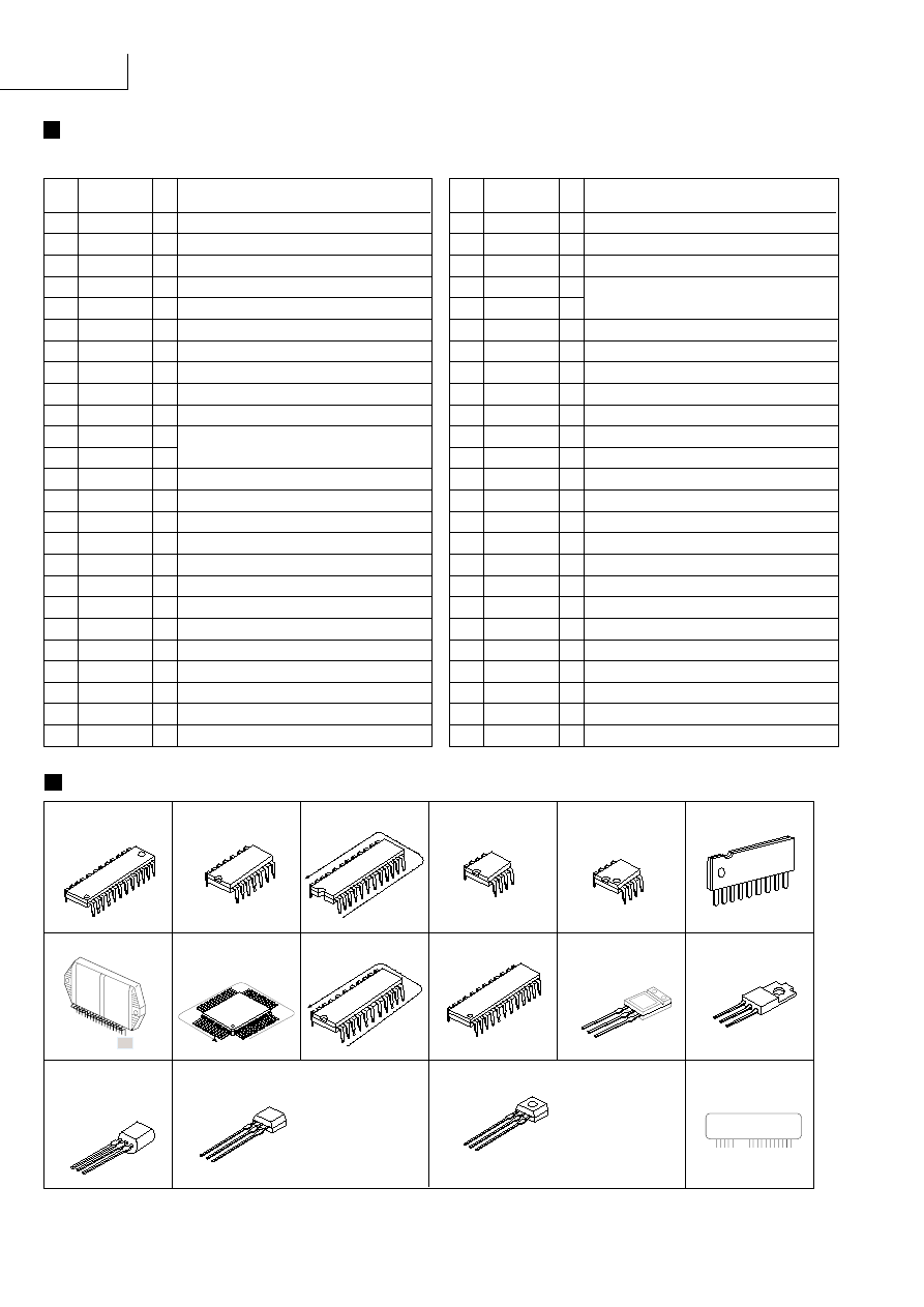
Terminal Guide of ICs, Transistors and Diodes
Pin
No.
Mark
I/O
Function
Pin
No.
Mark
I/O
Function
No.1
LA1832A
LC7218
1
12
24
13
NJM2279D
1
7
14
8
TC9163AN 28Pin
AN6558F
UPC4570C
1
4
5
8
BA6218
1
9
2SD2137PQTA
2SB1417PQTA
M5218P
LV1016L
1
12
24
13
LA2786L 42Pin
No.1
M38B53M4053F
80 Pin
No. 1
RSN307M44-P
1
18
28
26
2SD592AQSTA
2SA992EFTA
2SB621AQSTA
2SC3940AQSTA
2SA933SSTA
2SC1740SSTA
B
C
E
E
C
B
2SB1548PQAU
2SD2374PQAU
B
C
E
2SC2787LTA
2SC2785FETA
2SC3311ARTA
2SD1915FTA
E
C
B
RVTDTA113ZST
RVTDTA114EST
RVTDTC143XST
RVTDTA143XST
RVTDTC114YST
RVTDTA114YST
RVTDTA114EST
33~48 SEG16~SEG1 O FL segment signal output
49~58 DEG1~DEG10 O FL digit signal output
59
INIT_IN
I Diode input
60 VOL_DOWN O
61
VOL_UP
O
62
LOUDNESS Not used
63
IF_DATA
I Serial data signal
64
REC_MUTE Not used
65
TNR_CE
O Chip enable signal
66
SEL/TNR_CK O Serial clock signal
67
SEL/TNR_DT O Serial data signal
68
SEL_ST
O Level shift control terminal
69
OSD_ST
Not used
70
SURR/OSD_CK O Serial clock signal
71
SURR/OSD_DT O Serial data signal
72
SURR_CE O Chip enable signal
73
AVSS
GND for A-D conveter
74
VREF
I Reference voltage for A-D convertion
75
SD
I SD signal detect input
76
AC3_LED
Not used
77
HELP_LED O LED drive signal (HELP)
78 VIDEO_DET Not used
79
VIDEO_B O Video selector controloutput B
80
VIDEO_A O Video selector controloutput A
1~4 KEY4~KEY1 I Key matrix detect terminal
5
THERM/OVLD
I Thermal/Over load detect terminal
6
FM_ST
I Stereo signal detect terminal
7
6CH_ST
Not used
8
RDS_ST
Not used
9
REMOTE
I Remote control terminal
10
RESET
I Reset detect terminal
11
RDS_CK
Not used
12
RDS_DT
Not used
13
GND
GND terminal
14
XIN
I Crystal oscillator terminal
15
XOUT
O (4 MHz)
16
VDD
I Power supply terminal
17~21 SFC5~SFC1 O SFC LED indicator output
22
HOLD
I Power trip detection input
23
STANDBY_LED Not used
24
FAN_STOP Not used
25
RLY
O Power relay control output
26
TV/DVD
I TV/DVD select control input
27
LIMITTER O Power limitter control output
28
VEE
I FL driver pull down voltage
29
S/C_SP
O Surround/center speaker control output
30
SP_B
O Speaker B control output
31
SP_A
O Speaker A control output
32
AF_MUTE O Muting control output
Rotate control terminal of volume motor
B
C
E
1
4
5
8
STK311-010
BLUE
SA-EX310
MTZJ5R1BTA
MTZJ5R6BTA
MTZJ7R5CTA
MTZJ9R1CTA
MTZJ6R2BTA
MTZJ15CTA
MTZJ6R8BTA
MTZJ4R7BTA
MTZJ3R9ATA
MTZJ10CTA
MTZJ27DTA
MTZJ24DTA
RVD1SS133TA
1SR35200TB
1SS291TA
MA165TA
Ca
A
Cathode
Anode
Ca
Cathode
Anode
A
: +B line
: Main signal line
: B line
: AM signal line
: AM OSC signal line
: FM/AM signal line
: FM signal line
: FM OSC signal line
Signal line
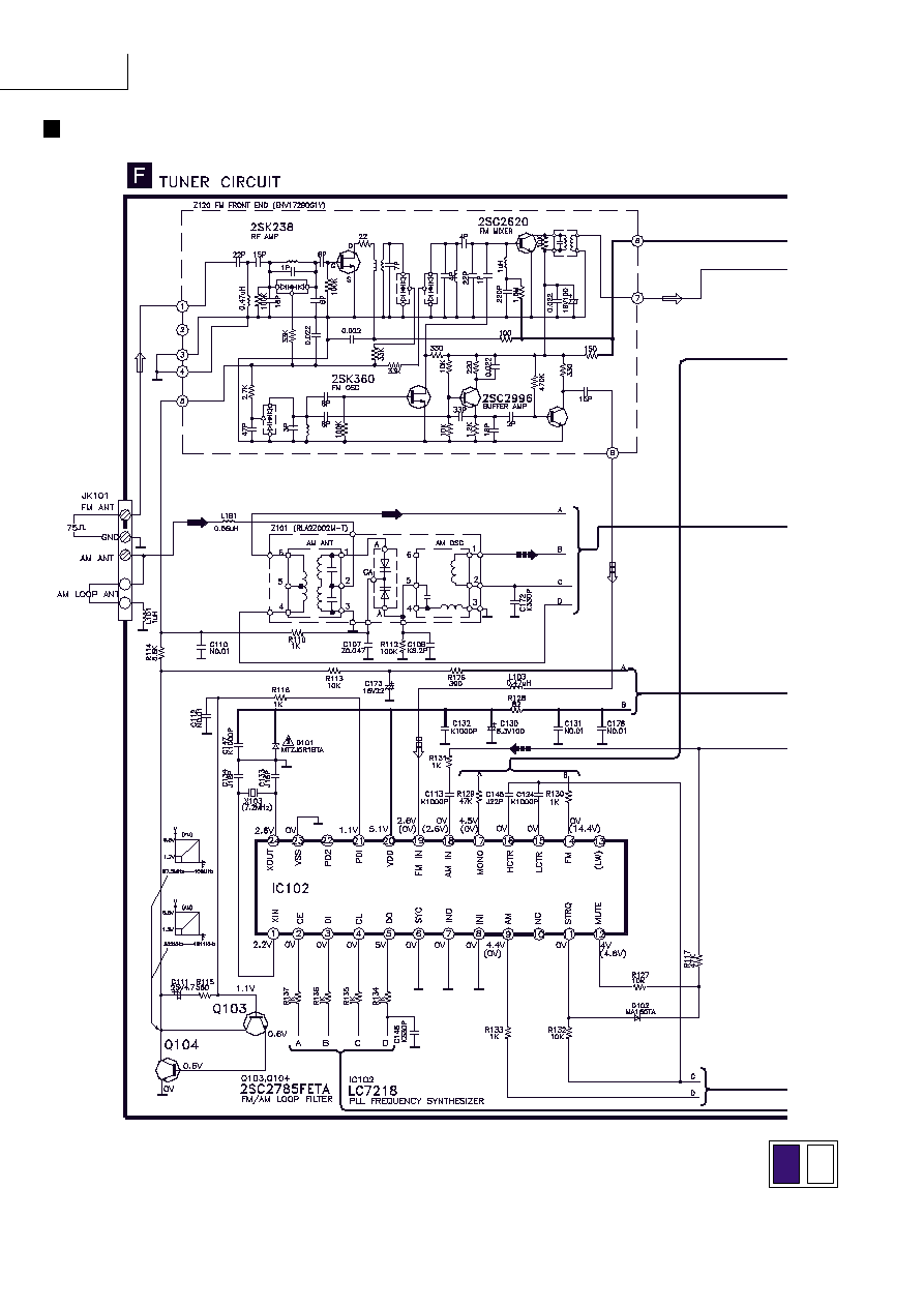
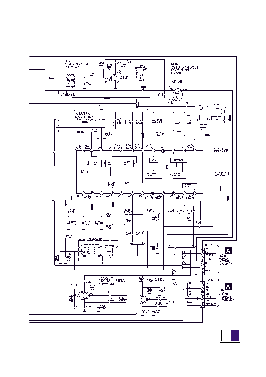
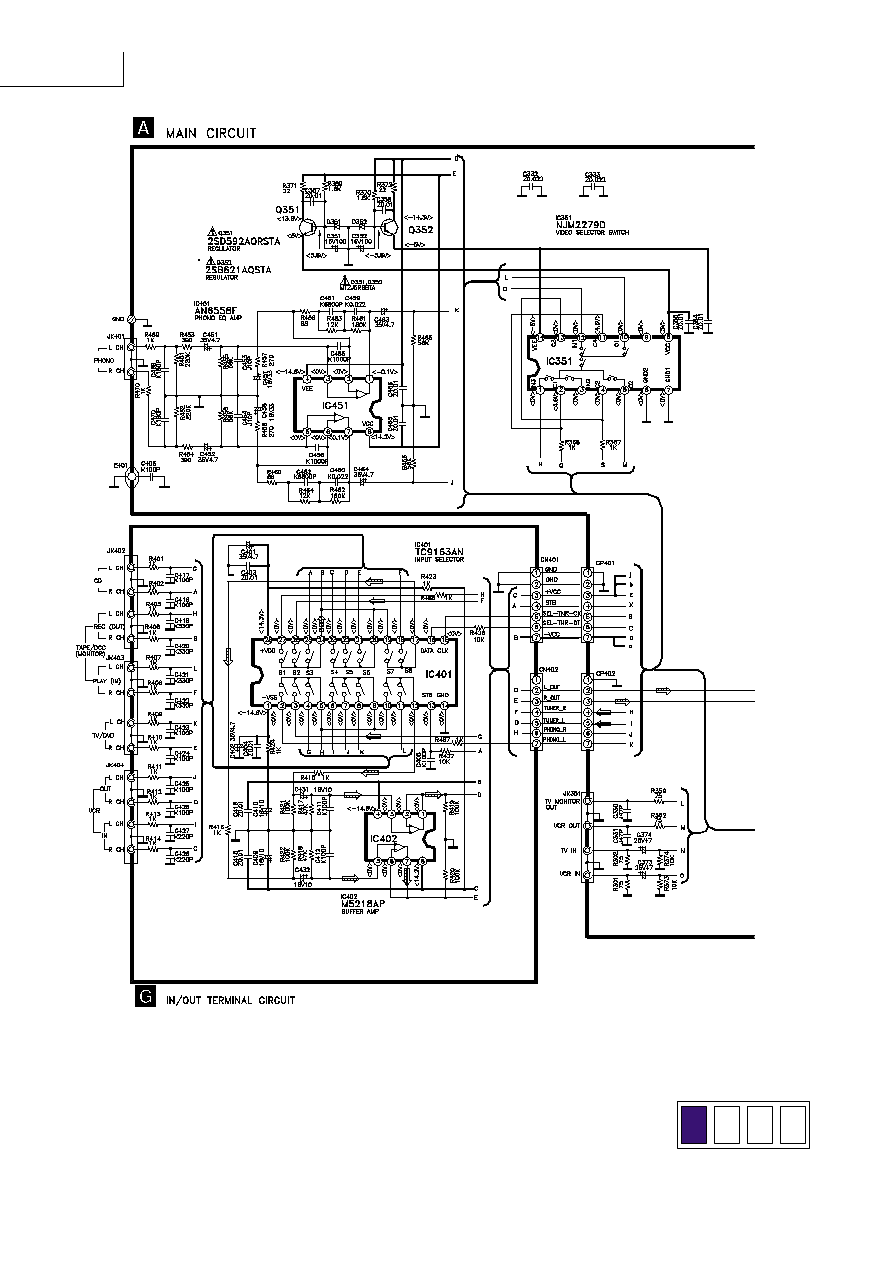
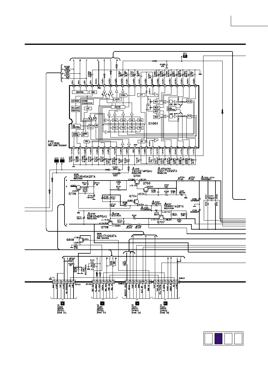
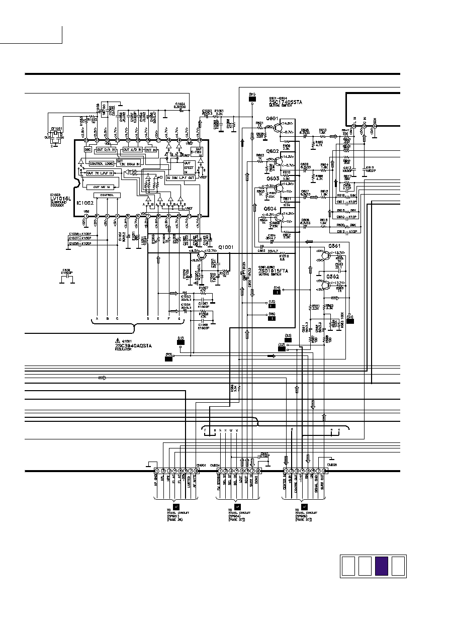
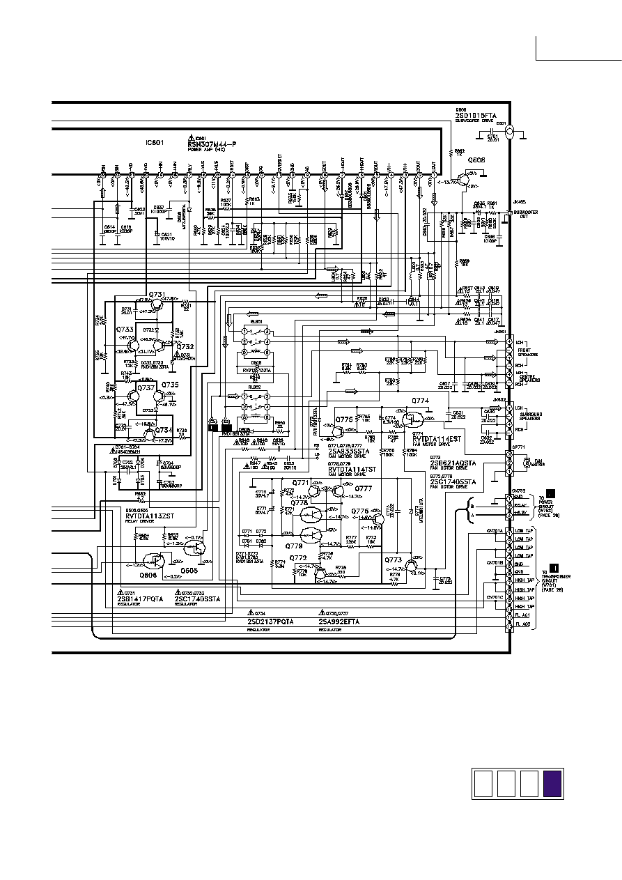
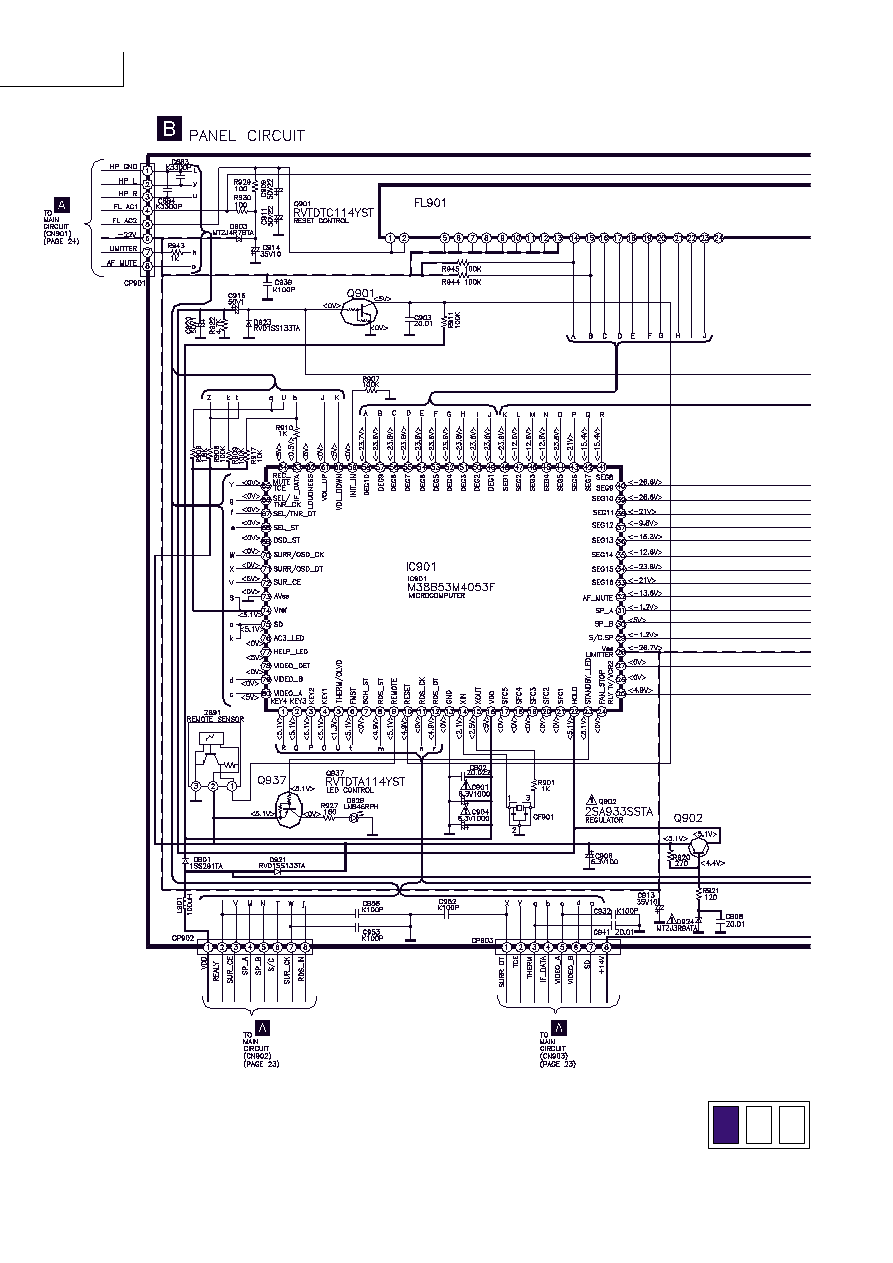
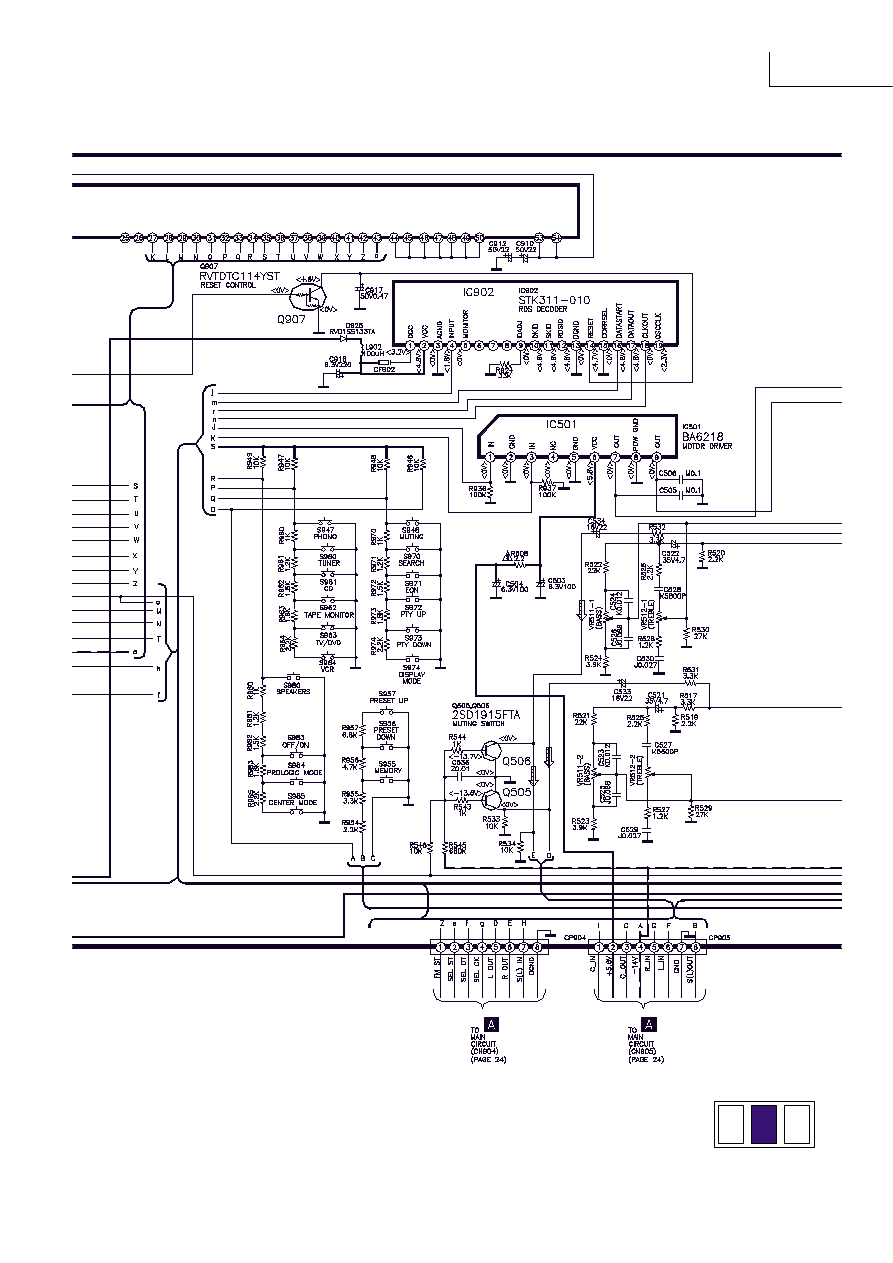
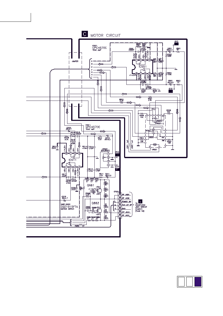
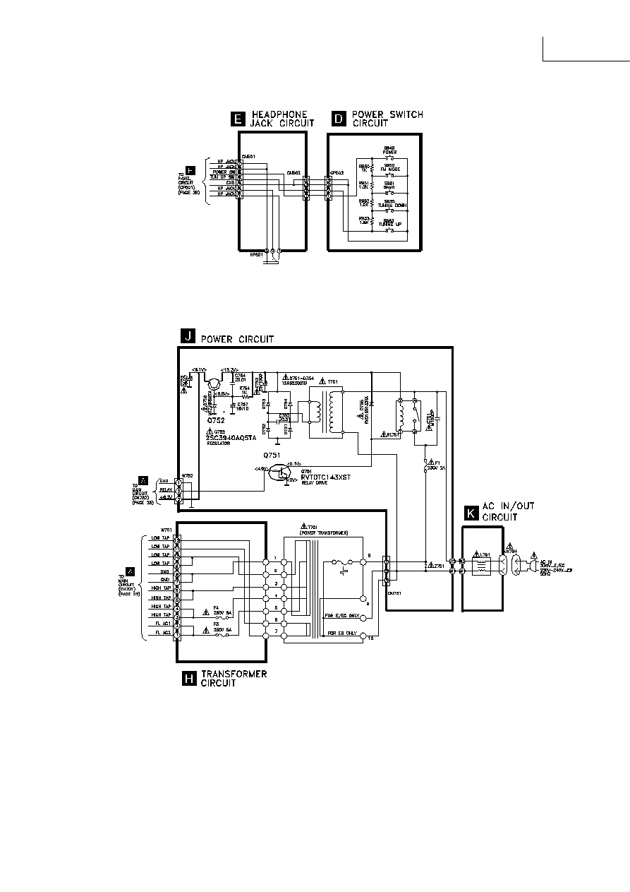
Schematic Diagram
(All schematic diagrams may be modified at any time with the development of new technology)
Note :
S946
:
Power switch
S947
:
Phono select switch
S948
:
Muting switch
S950
:
FM Auto/ Mono switch
S951
:
Band select switch
S952
:
Tuning decrease switch
S953
:
Tuning increase switch
S955
:
Memory manual/auto switch
S956
:
Preset decrease switch
S957
:
Preset increase switch
S960
:
Tuner select switch
S961
:
CD select switch
S962
:
Tape select switch
S963
:
TV/DVD select switch
S964
:
VCR select switch
S970
:
Search switch
S971
:
EON switch
S972
:
PTY up switch
S973
:
PTY down switch
S974
:
Display mode switch
S980
:
Speaker switch
S983
:
Dolby Pro Logic/SFC off on switch
S984
:
Dolby Pro Logic mode select switch
S985
:
Center mode select switch
VR501-1 ~ VR501-4 :
Volume control
VR502
:
Balance control
VR511-1 ~ VR511-2 :
Bass control
VR512-1 ~ VR512-2 :
Treble control
Importance safety notice:
Components identified by
mark have special characteristics important for safety. Furthermore, special parts which have purposes of
fire-retardant (resistors), high-quality sound (capacitors), low-noise (resistors), etc. are used. When replacing any of components, be sure
to use only manufacturer's specified parts shown in the parts list.
Caution !
IC, LSI and VLSI are sensitive to static electricity.
Secondary trouble can be prevented by taking care during repair.
Cover the parts boxes made of plastics with aluminium foil.
Ground the soldering iron.
Do not touch the pins of IC, LSI or VLSI with fingers directly.
Put a conductive mat on the work table.
The voltage value and waveforms are the reference voltage of this unit measured by DC electronic voltmeter (high impedance) and oscillo-
scope on the basis of chassis.
Accordingly, there may arise some error in voltage values and waveforms depending upon the internal impedance of the tester or the
measuring unit.
( ) ..... AM
< > ..... FM
1N5402BM21
SB360L6508
Ca
A
Cathode
Anode
Anode
Cathode
Ca
A
LN846RPH
SA-EX310
Schematic Diagram
SA-EX310
SA-EX310
SA-EX310
SA-EX310
SA-EX310
SA-EX310
SA-EX310
SA-EX310
SA-EX310
SA-EX310
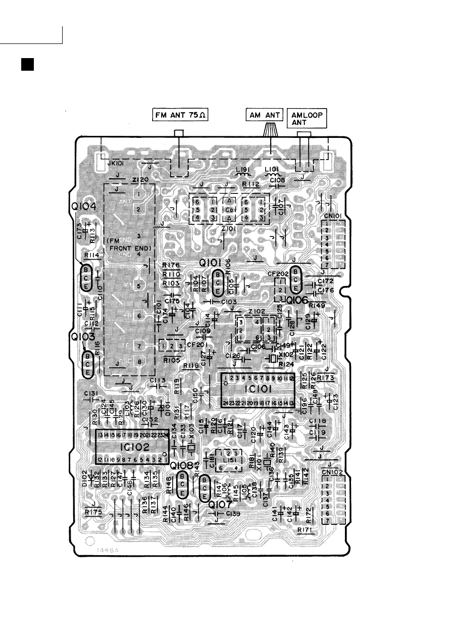
Printed Circuit Board
C
MOTOR P.C.B. (REP2445D-S)
B
PANEL P.C.B. (REP2445D-S)
E
HEADPHONE JACK P.C.B. (REP2445D-S)
SA-EX310
D
POWER SWITCH P.C.B. (REP2445D-S)
SA-EX310
A
MAIN P.C.B. (REP2444C-M)
SA-EX310
SA-EX310
F
TUNER P.C.B. (REP2158A-T).....EG
(REP2158D-T).....E/EB
SA-EX310
J
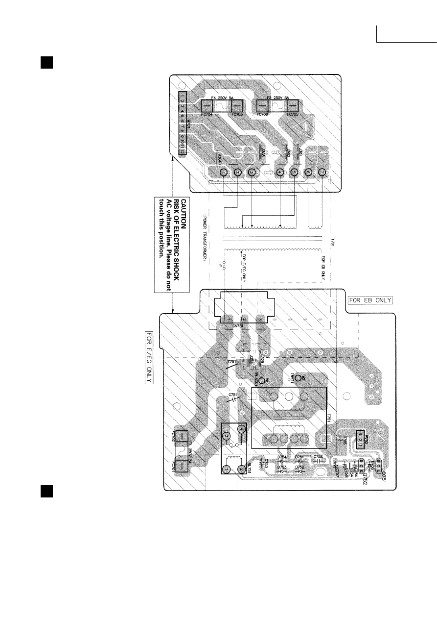
POWER P.C.B.
(REP2446D-P).....E/EG
(REP2446E-P).....EB
H
TRANSFORMER P.C.B.
(REP2444C-M)
SA-EX310
I
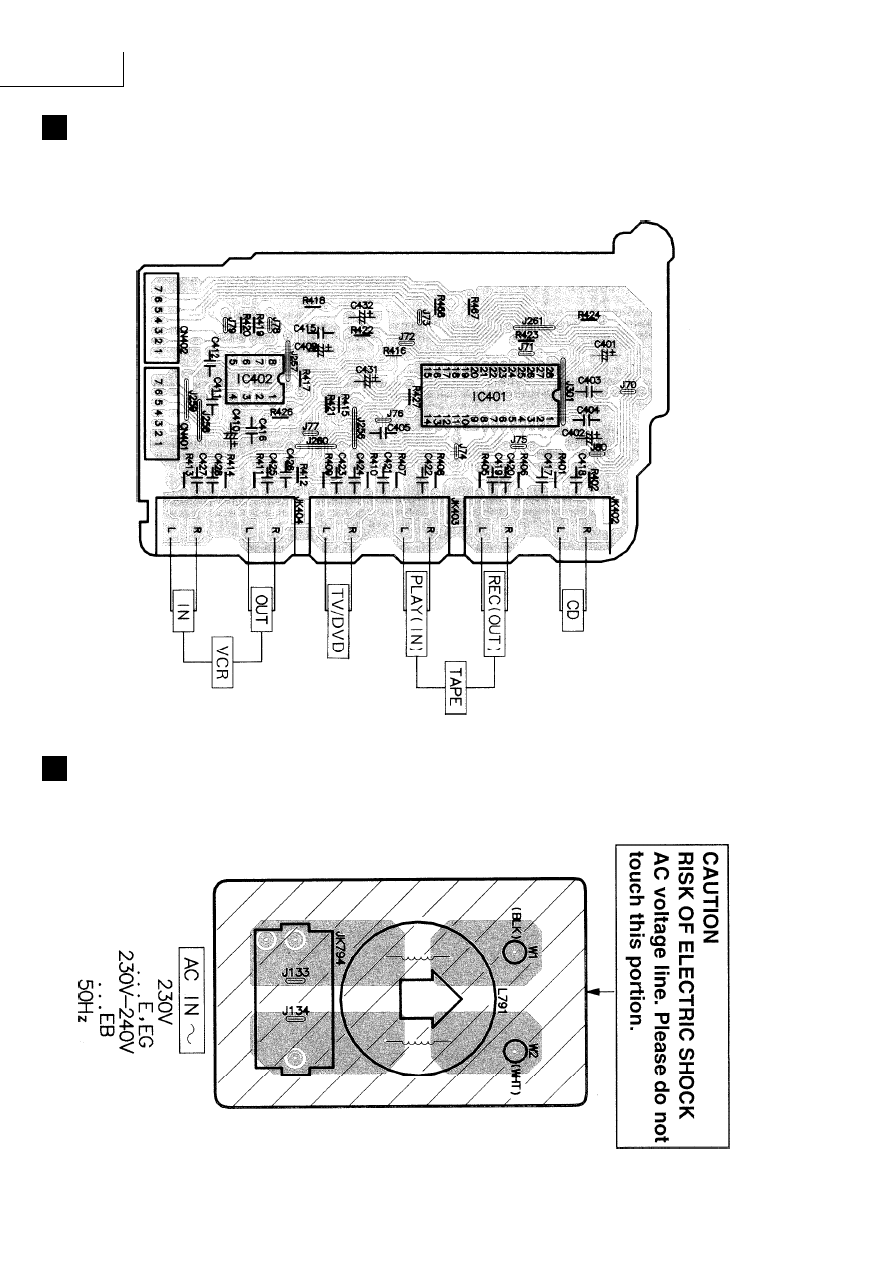
IN / OUT TERMINAL P.C.B.
(REP2446D-P).....E/EG
(REP2446E-P).....EB
K
AC IN/OUT P.C.B.
(REP2446D-P).....E/EG
(REP2446E-P).....EB
SA-EX310
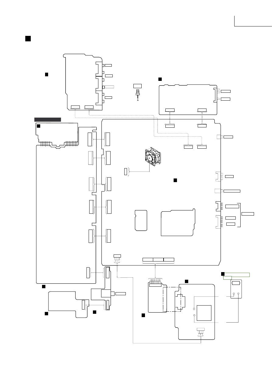
Wiring Connection Diagram
7 ..... 1
7 ..... 1
CN102
CN101
SOLDER
SIDE
JK101
FM ANT
AM ANT
1..........12
W701
4
.
1
.
CP502
CP905
CP903
CP902
CP901
7
.
.
.
.
.
1
CP501
CN905
7 ..... 1
7 ..... 1
7 ..... 1
7 ..... 1
CP101
CP102
CP401
CP402
CN903
CN902
CN901
1
2
3
CP771
CN502
CN501
7
.
.
.
.
.
1
4
.
1
.
SOLDER
SIDE
PHONO
JK401
VIDEO
JK351
SUB-WOOFER
JK405
SURROUND
R
L
CENTER
SPEAKERS
JK602
JK601
PHONE
HP601
COMPONENT
SIDE
COMPONENT
SIDE
SOLDER
SIDE
7 ..... 1
7 ..... 1
CN401
CN402
CD
REC (OUT)
PLAY (IN)
TAPE
JK402
JK403
JK404
VCR
OUT
IN
SOLDER
SIDE
TV/ DVD
W752
T751
CN751
COMPONENT
SIDE
T701
(POWER
TRANSFORMER)
3 2 1
COMPONENT
SIDE
W1
W2
JK794
W1 W2
BLACK
WHITE
JUMPER
FAN MOTOR
TUNER P.C.B
F
MAIN P.C.B
A
PANEL P.C.B
B
POWER SWITCH
P.C.B
D
HEADPHONE
JACK P.C.B
E
MOTOR P.C.B
C
TRANSFORMER
P.C.B
H
POWER P.C.B
J
IN / OUT
TERMINAL
P.C.B
G
FRONT
AC / IN OUT
P.C.B
K
GND
8
.
.
.
.
.
.
.
1
8
.
.
.
.
.
.
.
1
8
.
.
.
.
.
.
.
1
8
.
.
.
.
.
.
.
1
CP904
CN904
8
.
.
.
.
.
.
.
1
8
.
.
.
.
.
.
.
1
8
.
.
.
.
.
.
.
1
8
.
.
.
.
.
.
.
1
8
.
.
.
.
.
.
.
1
8
.
.
.
.
.
.
.
1
1 . . 4
CN701B
CN701C
1 . . 4
1 . . 4
CN701A
1 2 3
CN752
NOTE :
Dotted lines means direct
contact connectors ( no wires ).
R
L
SA-EX310
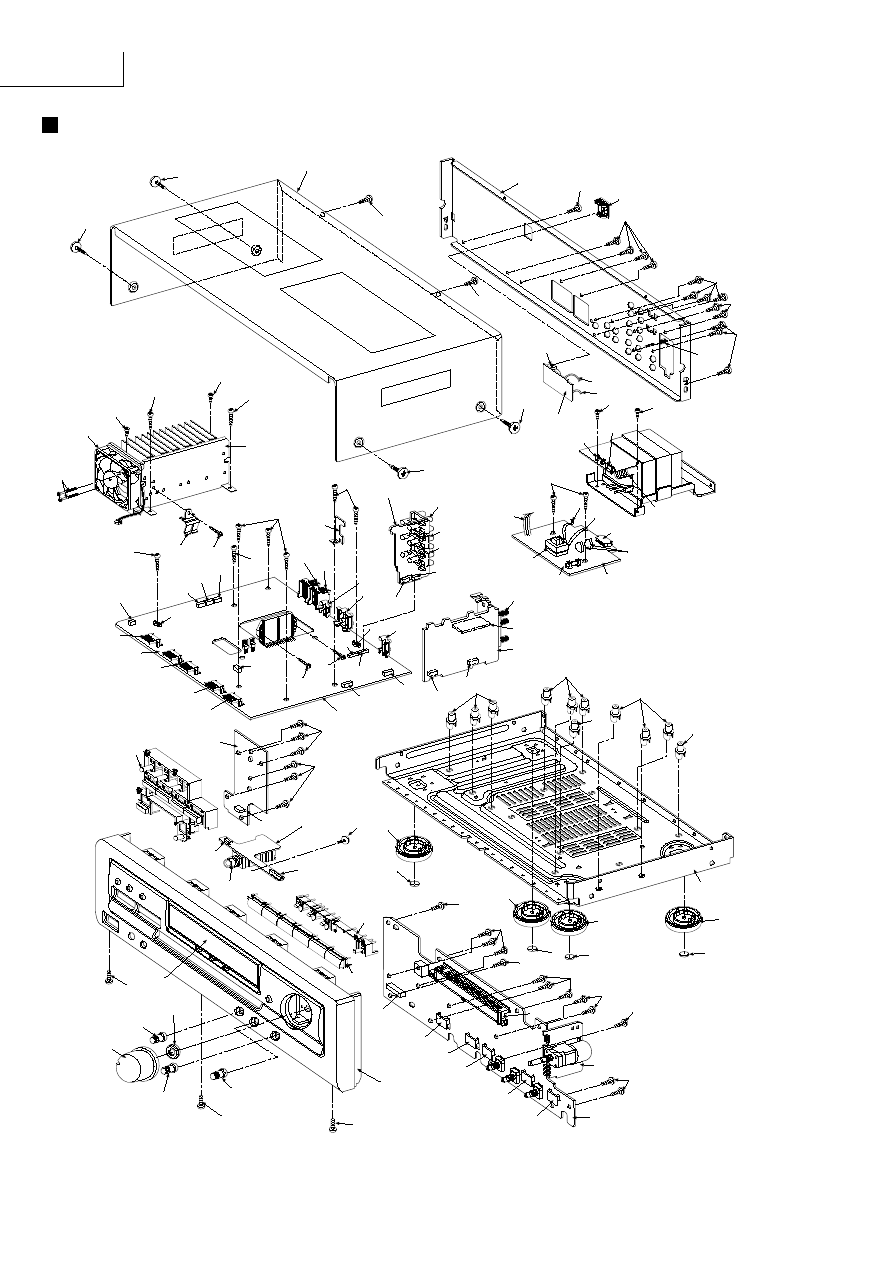
Cabinet Parts Location
30
30
3
24
30
30
30
JK402
JK403
JK404
CN401
CN402
JK101
(TUNER PACK
P.C.B)
CN101
CN102
CP101
JK401
CP401
CP402
E401
JK351
CP102
E601
JK601
JK405
JK602
26
CN752
CN901
CN902
CN903
CN904
CN905
29
29
(OPERATION
P.C.B)
4
CP502
CN502
CN501
5
6
29
29
29
29
29
CP501
CP901
CP902
CP903
19
(VOLUME P.C.B)
29
CP904
CP905
(PANEL P.C.B)
29
9
8
8
10
8
7
30
30
2
(HEADPHONE
P.C.B)
(TUNER P.C.B)
(MAIN P.C.B)
25
25
30
30
13
25
25
30
HP601
F1
CN751
(POWER P.C.B)
T751
W2
W1
W1
JK794
F4
F3
W701
W752
CN701A
CN701B
CN701C
20
(IN/OUT TERMINAL P.C.B)
(AC IN/OUT P.C.B)
23
26
28
28
26
22
31
16
26
26
26
31
31
14
14
14
14
14
18
15
28
26
28
1
27
W2
CP771
21
12
17
12
17
17
12
17
12
SA-EX310
Ref No.
Part No.
Part Name & Description
Remarks Ref No.
Part No.
Part Name & Description
Remarks Ref No.
Part No.
Part Name & Description
Remarks
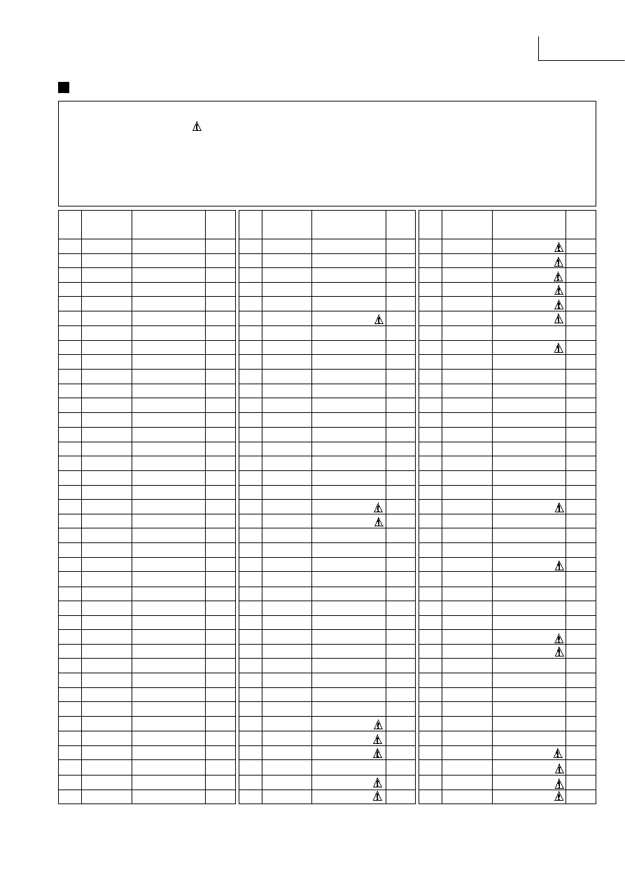
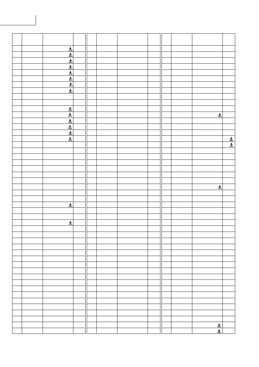
Replacement Parts List
Notes: * Important safety notice :
Components identified by mark have special characteristics important for safety.
Furthermore, special parts which have purposes of fire-retardant (resistors), high-quality sound (capacitors), low-noise (resistors), etc. are used.
When replacing any of components, be sure to use only manufacturer's specified parts shown in the parts list.
* The parenthesized in the Remarks columns specify the areas. (Refer to the cover page for area.)
Parts without these indication can be used for all areas.
* [M] in Remarks column indicates parts that are supplied by MESA.
* Remote Control Unit : Supply period for three years from terminal of production.
* The "(SF)" mark denotes the standard part.
CABINET AND CHASSIS
1
REM0069
FAN UNIT
[M]
2
RFKGEX310EK FRONT PANEL ASSY
[M]
3
RGR0251B-A
REAR PANEL
[M]EG E
3
RGR0251B-B
REAR PANEL
[M]EB
4
RGU1350-K
MODE BUTTON
[M]
5
RGU1352M-K
DOLBY BUTTON
[M]
6
RGU1493-K
SELECTOR BUTTON
[M]
7
RGW0243A-K
VOLUME KNOB
[M]
8
RGW0244-K1
BASS TREBLE KNOB
[M]
9
RHD26016
SCREW
[M]
10
RHN90001
M9 NUT
[M]
12
RKA0079-A
LEG
[M]
13
RKM0260D-K
TOP CABINET
[M]EG E
14
RKQ0089-J
PCB HOLDER
[M]
15
RKW0436E-Q
FL WINDOW
[M]
16
RMC0158-S
TRANSISTOR HOLDER
[M]
17
RMG0270-K
LEG CUSHION
[M]
18
RMK0350
BOTTOM CHASSIS
[M]
19
RMN0372
FL HOLDER
[M]
20
RMQ0709
TUNER PCB BRACKET
[M]
21
RMZ0339
ZNR COVER
[M]
22
RXX0186
HEAT SINK UNIT
[M]
23
SJS9231A
A/C INLET COVER
[M]
24
SNE2123
EARTH TERMINAL
[M]
25
SNE2129-1
SCREW (CABINET)
[M]
26
XTB3+20JFZ
SCREW
[M]
27
XTB3+30J
SCREW (FAN)
[M]
28
XTB3+8FFZ
SCREW
[M]
29
XTBS26+10J
SCREW (FRONT)
[M]
30
XTBS3+8JFZ1
SCREW
[M]
31
XTW3+15T
SCREW
[M]
INTEGRATED CIRCUITS
IC101 LA1832A
IC, IF/MPX
[M]
IC102 LC7218
IC, PLL
[M]
IC351 NJM2279D
IC, VIDEO SELECTOR
[M]
IC401 TC9163AN
IC, SELECTOR
[M]
IC402 M5218AP
IC, BUFFER AMP
[M]
IC451 AN6558F
IC, OP AMP
[M]
IC501 BA6218
IC, MOTOR DRIVER
[M]
IC511 UPC4570C
IC, TONE CONTROL
[M]
IC551 UPC4570C
IC, TONE CONTROL
[M]
IC601 RSN307M44-P
IC, HIC
[M]
IC901 M38B53M4053F IC, MICOM
[M]
IC902 STK311-010
IC, RDS DECODER
[M]
IC1001 LA2786L
IC, DPL
[M]
IC1002 LV1016L
IC, SURR DECODER
[M]
TRANSISTORS
Q101
2SC2787LTA
TRANSISTOR
[M]
Q103
2SC2785FETA
TRANSISTOR
[M]
Q104
2SC2785FETA
TRANSISTOR
[M]
Q106
RVTDTA143XST
TRANSISTOR
[M]
Q107
2SC3311ARTA
TRANSISTOR
[M]
Q108
2SC3311ARTA
TRANSISTOR
[M]
Q351
2SD592AQRSTA
TRANSISTOR
[M]
Q352
2SB621AQSTA
TRANSISTOR
[M]
Q505
2SD1915FTA
TRANSISTOR
[M]
Q506
2SD1915FTA
TRANSISTOR
[M]
Q561
2SD1915FTA
TRANSISTOR
[M]
Q562
2SD1915FTA
TRANSISTOR
[M]
Q601
2SC1740SSTA
TRANSISTOR
[M]
Q602
2SC1740SSTA
TRANSISTOR
[M]
Q603
2SC1740SSTA
TRANSISTOR
[M]
Q604
2SC1740SSTA
TRANSISTOR
[M]
Q605
RVTDTA113ZST
TRANSISTOR
[M]
Q606
RVTDTA113ZST
TRANSISTOR
[M]
Q608
2SD1915FTA
TRANSISTOR
[M]
Q681
2SD1915FTA
TRANSISTOR
[M]
Q682
2SD1915FTA
TRANSISTOR
[M]
Q701
2SD2374PQAU
TRANSISTOR
[M]
Q703
2SC1740SSTA
TRANSISTOR
[M]
Q704
2SC1740SSTA
TRANSISTOR
[M]
Q706
2SC3940AQSTA
TRANSISTOR
[M]
Q707
2SB621AQSTA
TRANSISTOR
[M]
Q708
2SB1548PQAU
TRANSISTOR
[M]
Q731
2SB1417PQTA
TRANSISTOR
[M]
Q732
2SC1740SSTA
TRANSISTOR
[M]
Q733
2SC1740SSTA
TRANSISTOR
[M]
Q734
2SD2137PQTA
TRANSISTOR
[M]
Q735
2SA992EFTA
TRANSISTOR
[M]
Q737
2SA992EFTA
TRANSISTOR
[M]
Q751
RVTDTC143XST
TRANSISTOR
[M]
Q752
2SC3940AQSTA
TRANSISTOR
[M]
Q771
2SA933SSTA
TRANSISTOR
[M]
Q772
2SC1740SSTA
TRANSISTOR
[M]
Q773
2SB621AQSTA
TRANSISTOR
[M]
Q774
RVTDTA114EST
TRANSISTOR
[M]
Q775
2SA933SSTA
TRANSISTOR
[M]
Q776
2SC1740SSTA
TRANSISTOR
[M]
Q777
2SA933SSTA
TRANSISTOR
[M]
Q778
RVTDTA114TST
TRANSISTOR
[M]
Q779
RVTDTA114TST
TRANSISTOR
[M]
Q901
RVTDTC114YST
TRANSISTOR
[M]
Q902
2SA933SSTA
TRANSISTOR
[M]
Q907
RVTDTC114YST
TRANSISTOR
[M]
Q909
2SC1740SSTA
TRANSISTOR
[M]
Q937
RVTDTA114YST
TRANSISTOR
[M]
Q1001 2SC3940AQSTA
TRANSISTOR
[M]
DIODES
D101
MTZJ5R1BTA
DIODE
[M]
D102
MA165TA
DIODE
[M]
D351
MTZJ5R6BTA
DIODE
[M]
D352
MTZJ5R6BTA
DIODE
[M]
D401
MTZJ7R5CTA
DIODE
[M]
D601
SB360L6508
DIODE
[M]
D602
SB360L6508
DIODE
[M]
D605
RVD1SS133TA
DIODE
[M]
D606
RVD1SS133TA
DIODE
[M]
D608
MTZJ6R2BTA
DIODE
[M]
D701
1N5402BM21
DIODE
[M]
D702
1N5402BM21
DIODE
[M]
D703
1N5402BM21
DIODE
[M]
D704
1N5402BM21
DIODE
[M]
SA-EX310
Ref No.
Part No.
Part Name & Description
Remarks Ref No.
Part No.
Part Name & Description
Remarks Ref No.
Part No.
Part Name & Description
Remarks
D705
MTZJ6R2BTA
DIODE
[M]
D707
MTZJ27DTA
DIODE
[M]
D708
MTZJ15CTA
DIODE
[M]
D721
1N5402BM21
DIODE
[M]
D722
1N5402BM21
DIODE
[M]
D723
1N5402BM21
DIODE
[M]
D724
1N5402BM21
DIODE
[M]
D731
MTZJ24DTA
DIODE
[M]
D732
RVD1SS133TA
DIODE
[M]
D733
RVD1SS133TA
DIODE
[M]
D751
1SR35200TB
DIODE
[M]
D752
1SR35200TB
DIODE
[M]
D753
1SR35200TB
DIODE
[M]
D754
1SR35200TB
DIODE
[M]
D755
RVD1SS133TA
DIODE
[M]
D756
MTZJ6R8BTA
DIODE
[M]
D771
RVD1SS133TA
DIODE
[M]
D772
RVD1SS133TA
DIODE
[M]
D773
MTZJ9R1CTA
DIODE
[M]
D775
RVD1SS133TA
DIODE
[M]
D781
RVD1SS133TA
DIODE
[M]
D782
RVD1SS133TA
DIODE
[M]
D901
1SS291TA
DIODE
[M]
D903
MTZJ4R7BTA
DIODE
[M]
D921
RVD1SS133TA
DIODE
[M]
D923
RVD1SS133TA
DIODE
[M]
D924
MTZJ3R9ATA
DIODE
[M]
D925
RVD1SS133TA
DIODE
[M]
D929
LN846RPH
DIODE
[M]
D1001
MTZJ10CTA
DIODE
[M]
VARIABLE RESISTORS
VR501 EUWMRH026B15
VR, MOTOR
[M]
VR502 EVJ02QF01G15
VR, BALANCE CONTROL
[M]
VR511 EVJYA1F01C15
VR, TONE CONTROL
[M]
VR512 EVJYA1F01C15
VR, TONE CONTROL
[M]
SWITCHES
S946
EVQ21405R
SW, POWER
[M]
S947
EVQ21405R
SW, PHONO
[M]
S948
EVQ21405R
SW, MUTING
[M]
S950
EVQ21405R
SW, FM MODE
[M]
S951
EVQ21405R
SW, BAND
[M]
S952
EVQ21405R
SW, TUNING DOWN
[M]
S953
EVQ21405R
SW, TUNING UP
[M]
S955
EVQ21405R
SW, MEMORY
[M]
S956
EVQ21405R
SW, PRESET DOWN
[M]
S957
EVQ21405R
SW, PRESET UP
[M]
S960
EVQ21405R
SW, TUNER
[M]
S961
EVQ21405R
SW, CD
[M]
S962
EVQ21405R
SW, TAPE
[M]
S963
EVQ21405R
SW, TV/DVD
[M]
S964
EVQ21405R
SW, VCR
[M]
S970
EVQ21405R
SW, SEARCH
[M]
S971
EVQ21405R
SW, EON
[M]
S972
EVQ21405R
SW, PTY UP
[M]
S973
EVQ21405R
SW, PTY DOWN
[M]
S974
EVQ21405R
SW, DISPLAY MODE
[M]
S980
EVQ21405R
SW, SPEAKERS
[M]
S983
EVQ21405R
SW, OFF/ON
[M]
S984
EVQ21405R
SW, PRO-LOGIC
[M]
S985
EVQ21405R
SW, CENTER MODE
[M]
CONNECTORS
CN101 RJU057W007
7P CONNECTOR
[M]
CN102 RJU057W007
7P CONNECTOR
[M]
CN401 RJU100W07
7P CONNECTOR
[M]
CN402 RJU100W07
7P CONNECTOR
[M]
CN501 RJU100W07
7P CONNECTOR
[M]
CN502 RJU100W04
4P CONNECTOR
[M]
CN701A RJS1A6604T1
4P TAPING CONNECTOR
[M]
CN701B RJS1A6604T1
4P TAPING CONNECTOR
[M]
CN701C RJS1A6604T1
4P TAPING CONNECTOR
[M]
CN751
SJS305-1
3P CONNECTOR
[M]
CN752 RJS1A6603T1
3 PIN TAPING CONNECT
[M]
CN901 RJU003K008M1
BOAD IN CONNECTOR
[M]
CN902 RJU003K008M1
BOAD IN CONNECTOR
[M]
CN903 RJU003K008M1
BOAD IN CONNECTOR
[M]
CN904 RJU003K008M1
BOAD IN CONNECTOR
[M]
CN905 RJU003K008M1
BOAD IN CONNECTOR
[M]
CP101
RJT057W007-1
7P CONNECTOR
[M]
CP102
RJT057W007-1
7P CONNECTOR
[M]
CP401
RJT100W07
7P CONNECTOR
[M]
CP402
RJT100W07
7P CONNECTOR
[M]
CP501
RJT100W07
7P CONNECTOR
[M]
CP502
RJT100W04
4P CONNECTOR
[M]
CP771
RJP3G4YA
CONNECTOR
[M]
CP901
RJT003K008M1
8P CONNECTOR
[M]
CP902
RJT003K008M1
8P CONNECTOR
[M]
CP903
RJT003K008M1
8P CONNECTOR
[M]
CP904
RJT003K008M1
8P CONNECTOR
[M]
CP905
RJT003K008M1
8P CONNECTOR
[M]
COILS & TRANSFORMERS
L101
ELESN1R0MA
CHOKE COIL
[M]
L103
ELEXTR47MA9
CHOKE COIL
[M]
L105
RLQZB822KT-D
TAPING COIL
[M]
L106
RLQZB822KT-D
TAPING COIL
[M]
L151
SLM1B10-1M
A.B. FILTER
[M]
L191
ELESNR56MA
CHOKE COIL
[M]
L501
RLQZP1R0KT-Y
AXIAL COIL
[M]
L502
RLQZP1R0KT-Y
AXIAL COIL
[M]
L601
RLQYR73MW-E
CHOKE COIL
[M]
L602
RLQYR73MW-E
CHOKE COIL
[M]
L603
RLQYR73MW-E
CHOKE COIL
[M]
L604
RLQYR73MW-E
CHOKE COIL
[M]
L751
ELESN101KA
CHOKE COIL
[M]
L791
SLQZ650MH49
AC LINE COIL
[M]
L901
RLQB101KTA-Y
CHOKE COIL
[M]
L902
RLQZP101KT-Y
AXIAL COIL
[M]
L1051
ELESN101KA
CHOKE COIL
[M]
T701
RTP1N5B025-X
POWER TRANSFORMER
[M]
T751
RTP1I5E006
TRANSFORMER (SMALL)
[M]
COMPONENT COMBINATION
Z101
RLA2Z002M-T
AM ANT. COIL
[M]
Z102
RLI2Z006M-T
AM IFT
[M]
Z120
ENV17290G1R
FM TUNER PACK
[M]EG
Z120
ENV17290G1Y
FM TUNER PACK
[M]EB E
Z751
ERZV10V511CS
ZNR
[M]
Z891
RCDSPS4242N
REMOTE SENSOR
[M]
CERAMIC FILTERS
CF201 RLFFETNGD01L
CERAMIC FILTER
[M]
CF202 RLFFETMGD01L
CERAMIC FILTER
[M]
CF901 RVBCST4R00MT
CERAMIC OSCILLATOR
[M]
CF902 RSXZ456KM07M
CERAMIC OSCILLATOR
[M]
CF1051 EF0EC8004T4
CERAMIC OSCILLATOR
[M]
OSCILLATORS
X101
RSXZ456KM07M
CERAMIC OSCILLATOR
[M]
X102
RLFDGTD01I
FM REZONATOR
[M]
X103
SVQ49U722T-S
CERAMIC 7.2MHz
[M]
DISPLAY TUBE
FL901
RSL0233-F
FL
[M]
EARTH TERMINALS
E401
SNE1004-2
EARTH TERMINAL
[M]
E601
SNE1004-2
EARTH TERMINAL
[M]
FUSES
F1
XBA2C20TB0
FUSE
[M]
F3
XBA2C50TB0
FUSE
[M]
SA-EX310
Ref No.
Part No.
Part Name & Description
Remarks Ref No.
Part No.
Part Name & Description
Remarks Ref No.
Part No.
Part Name & Description
Remarks
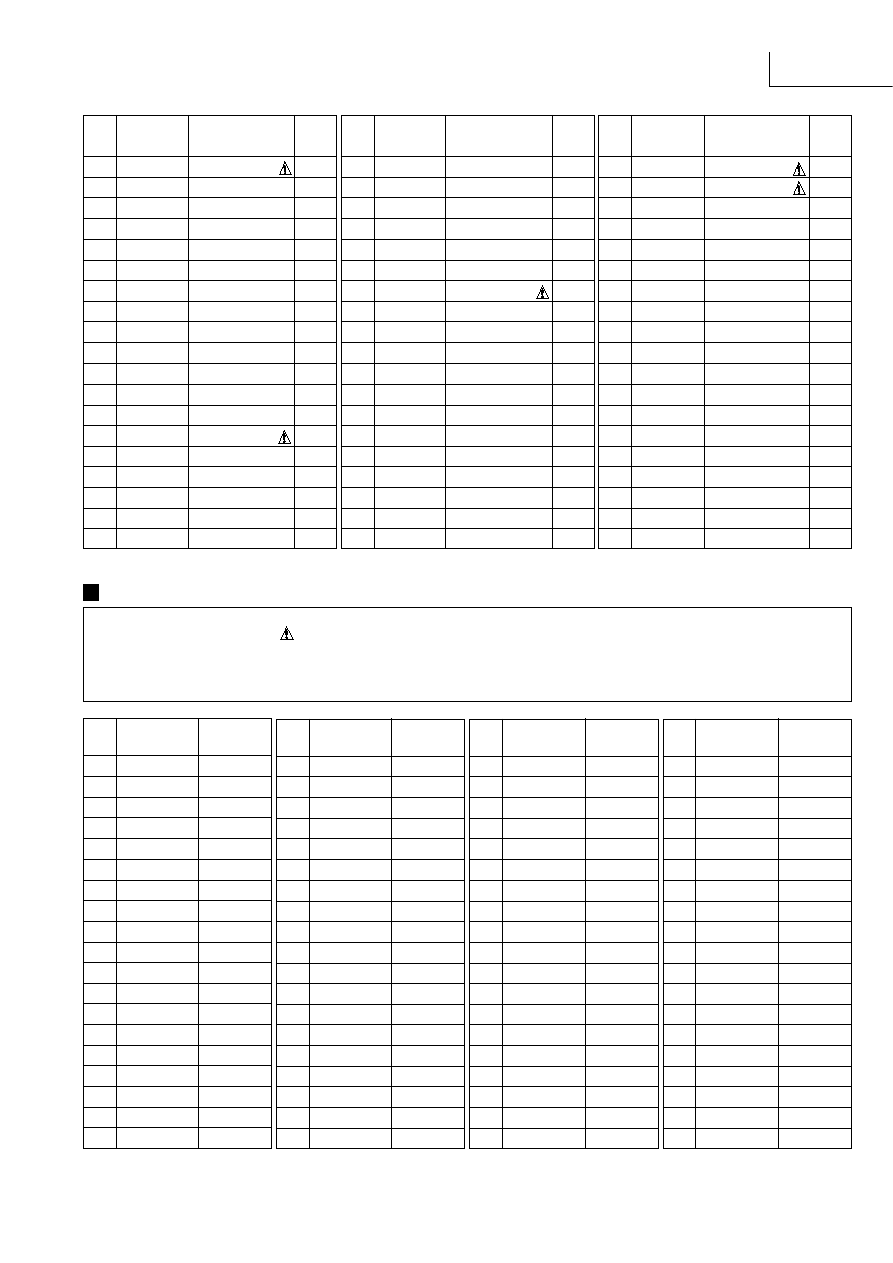
Ref No.
Part No.
Values & Remarks
Notes : * Important safety notice:
Components identified by
mark have special characteristics important for safety.
Furthermore, special parts which have purposes of fire-retardant (resistors), high-quality sound (capacitors), low-noise (resistors),etc. are used.
When replacing any of components, be sure to use only manufacturer's specified parts shown in the parts list.
* Capacitor values are in microfarad (
µ
F) unless specified otherwise, P=Pico-farads (pF) F=Farads (F)
* Resistors values are in ohms, unless specified otherwise, 1k=1,000(OHM), 1M=1,000k(OHM)
Resistors & Capacitors
F4
XBA2C50TB0
FUSE
[M]
FUSE CLIPS
FC701 EYF52BC
FUSE HOLDER
[M]
FC702 EYF52BC
FUSE HOLDER
[M]
FC703 EYF52BC
FUSE HOLDER
[M]
FC704 EYF52BC
FUSE HOLDER
[M]
FC705 EYF52BC
FUSE HOLDER
[M]
FC706 EYF52BC
FUSE HOLDER
[M]
RELAYS
RL601
RSY0013M-0
RELAY
[M]
RL602
RSY0013M-0
RELAY
[M]
RL751
RSY0019M-0
12V TV-5 RELAY
[M]
JACKS
JK101
RJH4202
JK, ANT TERMINAL
[M]
JK351
SJF3069-3N
JK, RCA PIN
[M]
JK401
SJF3068-7N
JK, RCA TERMINAL
[M]
JK402
SJF3069N
JK, LINE IN
[M]
JK403
SJF3069N
JK, LINE IN
[M]
JK404
SJF3069N
JK, LINE IN
[M]
JK405
SJFD7
JK, FM MULTI OUT
[M]
JK601
RJH5601
JK, SP TERMINAL
[M]
JK602
RJR0054
JK, SP TERMINAL
[M]
JK794
SJS9231-1B
JK, AC IN
[M]
HEADPHONE
HP601
RJJ63TS01
HEADPHONE JACK
[M]
PACKING MATERIALS
P1
RPG3462
PACKING CASE
[M]E
P2
RPFX0005
MIRAMAT BAG
[M]
P3
RPN0865
POLYFOAM
[M]
ACCESSORIES
A1
EUR644377
REMOTE CONTROL
[M]
A1-1
UR64EC1822-3
REMOTE CONTROL COVER
[M]
A2
RJA0019-2K
AC CORD (SF)
[M]EG E
A2
VJA0733
AC CORD (SF)
[M]EB
A3
RFKSEX310EK
INSTR. MANUAL ASSY
[M]E
A3
RFKSEX310EBK
INSTR. MANUAL ASSY
[M]EB
A3
RFKSEX310EGK
INSTR. MANUAL ASSY
[M]EG
A4
RSA0007
FM ANTENA
[M]
A5
RSA0010
LOOP ANT UNIT
[M]
A6
SJP9009
ANT ADAPTER
[M]EB
A7
SPSD152
ACCESSORY BOX
[M]
A8
RPG3592
GIFT BOX
[M]EB EG
WIRE
W1
REE0814
WIRE
[M]
W2
REE0818
WIRE
[M]
Ref No.
Part No.
Values & Remarks
Ref No.
Part No.
Values & Remarks
Ref No.
Part No.
Values & Remarks
RESISTORS
R103
ERDS2TJ101T
100
1/4W [M]
R104
ERDS2TJ102T
1K
1/4W [M]
R105
ERDS2TJ471T
470
1/4W [M]
R106
ERDS2TJ224T
220K
1/4W [M]
R107
ERDS2TJ471T
470
1/4W [M]
R110
ERDS2TJ102T
1K
1/4W [M]
R112
ERDS2TJ104T
100K
1/4W [M]
R113
ERDS2TJ103T
10K
1/4W [M]
R114
ERDS2TJ562T
5.6K
1/4W [M]
R115
ERDS2TJ561T
560
1/4W [M]
R116
ERDS2TJ102T
1K
1/4W [M]
R117
ERDS2TJ473T
47K
1/4W [M]
R118
ERDS2TJ562T
5.6K
1/4W [M]
R119
ERDS2TJ183T
18K
1/4W [M]
R120
ERDS2TJ473T
47K
1/4W [M]
R121
ERDS2TJ332T
3.3K
1/4W [M]
R122
ERDS2TJ272T
2.7K
1/4W [M]
R124
ERDS2TJ271T
270
1/4W [M]
R125
ERDS2TJ472T
4.7K
1/4W [M]
R126
ERDS2TJ472T
4.7K
1/4W [M]
R127
ERDS2TJ103T
10K
1/4W [M]
R128
ERDS2TJ820T
82
1/4W [M]
R129
ERDS2TJ473T
47K
1/4W [M]
R130
ERDS2TJ102T
1K
1/4W [M]
R131
ERDS2TJ102T
1K
1/4W [M]
R132
ERDS2TJ103T
10K
1/4W [M]
R133
ERDS2TJ102T
1K
1/4W [M]
R134
ERDS2TJ102T
1K
1/4W [M]
R135
ERDS2TJ102T
1K
1/4W [M]
R136
ERDS2TJ102T
1K
1/4W [M]
R137
ERDS2TJ102T
1K
1/4W [M]
R139
ERDS2TJ272T
2.7K
1/4W [M]
R140
ERDS2TJ272T
2.7K
1/4W [M]
R141
ERDS2TJ102T
1K
1/4W [M]
R142
ERDS2TJ102T
1K
1/4W [M]
R143
ERDS2TJ222T
2.2K
1/4W [M]
R144
ERDS2TJ222T
2.2K
1/4W [M]
R145
ERDS2TJ102T (EB,E)
1K
1/4W [M]
R145
ERDS2TJ561T (EG)
560
1/4W [M]
R146
ERDS2TJ102T (EB,E)
1K
1/4W [M]
R146
ERDS2TJ561T (EG)
560
1/4W [M]
R147
ERDS2TJ474T
470K
1/4W [M]
R148
ERDS2TJ474T
470K
1/4W [M]
R149
ERDS2TJ680T
68
1/4W [M]
R171
ERDS2TJ102T
1K
1/4W [M]
R172
ERDS2TJ102T
1K
1/4W [M]
R173
ERDS2TJ471T
470
1/4W [M]
R175
ERDS2TJ102T
1K
1/4W [M]
R176
ERDS2TJ391T
390
1/4W [M]
R181
ERDS2TJ332T
3.3K
1/4W [M]
R301
ERDS2TJ750T
75
1/4W [M]
R302
ERDS2TJ750T
75
1/4W [M]
R359
ERDS2TJ750T
75
1/4W [M]
R362
ERDS2TJ750T
75
1/4W [M]
R367
ERDS2TJ102T
1K
1/4W [M]
R368
ERDS2TJ102T
1K
1/4W [M]
R369
ERDS2TJ182T
1.8K
1/4W [M]
R370
ERDS2TJ182T
1.8K
1/4W [M]
R371
ERD2FCVG220T
22
1/4W [M]
R372
ERD2FCVG220T
22
1/4W [M]
R373
ERDS2TJ103T
10K
1/4W [M]
R374
ERDS2TJ103T
10K
1/4W [M]
R401
ERDS2TJ102T
1K
1/4W [M]
R402
ERDS2TJ102T
1K
1/4W [M]
R405
ERDS2TJ102T
1K
1/4W [M]
R406
ERDS2TJ102T
1K
1/4W [M]
R407
ERDS2TJ102T
1K
1/4W [M]
R408
ERDS2TJ102T
1K
1/4W [M]
R409
ERDS2TJ102T
1K
1/4W [M]
R410
ERDS2TJ102T
1K
1/4W [M]
R411
ERDS2TJ102T
1K
1/4W [M]
R412
ERDS2TJ102T
1K
1/4W [M]
R413
ERDS2TJ102T
1K
1/4W [M]
R414
ERDS2TJ102T
1K
1/4W [M]
SA-EX310
Ref No.
Part No.
Values & Remarks
Ref No.
Part No.
Values & Remarks
Ref No.
Part No.
Values & Remarks Ref No.
Part No.
Values & Remarks
R415
ERDS2TJ102T
1K
1/4W [M]
R416
ERDS2TJ102T
1K
1/4W [M]
R417
ERDS2TJ473T
47K
1/4W [M]
R418
ERDS2TJ473T
47K
1/4W [M]
R419
ERDS2TJ104T
100K
1/4W [M]
R420
ERDS2TJ104T
100K
1/4W [M]
R421
ERDS2TJ104T
100K
1/4W [M]
R422
ERDS2TJ104T
100K
1/4W [M]
R423
ERDS2TJ102T
1K
1/4W [M]
R424
ERDS2TJ102T
1K
1/4W [M]
R425
ERDS2TJ103T
10K
1/4W [M]
R426
ERDS2TJ103T
10K
1/4W [M]
R427
ERDS2TJ103T
10K
1/4W [M]
R440
ERDS1FVJ820T
82
1/2W [M]
R441
ERDS2TJ473T
47K
1/4W [M]
R442
ERDS2TJ473T
47K
1/4W [M]
R443
ERDS2TJ330T
33
1/4W [M]
R451
ERDS2TJ224T
220K
1/4W [M]
R452
ERDS2TJ224T
220K
1/4W [M]
R453
ERDS2TJ391T
390
1/4W [M]
R454
ERDS2TJ391T
390
1/4W [M]
R455
ERDS2TJ563T
56K
1/4W [M]
R456
ERDS2TJ563T
56K
1/4W [M]
R457
ERDS2TJ271T
270
1/4W [M]
R458
ERDS2TJ271T
270
1/4W [M]
R459
ERDS2TJ680T
68
1/4W [M]
R460
ERDS2TJ680T
68
1/4W [M]
R461
ERDS2TJ184T
180K
1/4W [M]
R462
ERDS2TJ184T
180K
1/4W [M]
R463
ERDS2TJ123T
12K
1/4W [M]
R464
ERDS2TJ123T
12K
1/4W [M]
R465
ERDS2TJ563T
56K
1/4W [M]
R466
ERDS2TJ563T
56K
1/4W [M]
R467
ERDS2TJ102T
1K
1/4W [M]
R468
ERDS2TJ102T
1K
1/4W [M]
R469
ERDS2TJ102T
1K
1/4W [M]
R470
ERDS2TJ102T
1K
1/4W [M]
R501
ERDS2TJ222T
2.2K
1/4W [M]
R502
ERDS2TJ222T
2.2K
1/4W [M]
R503
ERDS2TJ103T
10K
1/4W [M]
R504
ERDS2TJ103T
10K
1/4W [M]
R505
ERDS2TJ103T
10K
1/4W [M]
R506
ERDS2TJ103T
10K
1/4W [M]
R508
ERDS1FVJ2R2T
2.2
1/2W [M]
R511
ERDS2TJ471T
470
1/4W [M]
R512
ERDS2TJ471T
470
1/4W [M]
R513
ERDS2TJ474T
470K
1/4W [M]
R514
ERDS2TJ474T
470K
1/4W [M]
R515
ERDS2TJ474T
470K
1/4W [M]
R516
ERDS2TJ474T
470K
1/4W [M]
R517
ERDS2TJ332T
3.3K
1/4W [M]
R518
ERDS2TJ332T
3.3K
1/4W [M]
R519
ERDS2TJ222T
2.2K
1/4W [M]
R520
ERDS2TJ222T
2.2K
1/4W [M]
R521
ERDS2TJ223T
22K
1/4W [M]
R522
ERDS2TJ223T
22K
1/4W [M]
R523
ERDS2TJ392T
3.9K
1/4W [M]
R524
ERDS2TJ392T
3.9K
1/4W [M]
R525
ERDS2TJ222T
2.2K
1/4W [M]
R526
ERDS2TJ222T
2.2K
1/4W [M]
R527
ERDS2TJ122T
1.2K
1/4W [M]
R528
ERDS2TJ122T
1.2K
1/4W [M]
R529
ERDS2TJ273T
27K
1/4W [M]
R530
ERDS2TJ273T
27K
1/4W [M]
R531
ERDS2TJ332T
3.3K
1/4W [M]
R532
ERDS2TJ332T
3.3K
1/4W [M]
R533
ERDS2TJ103T
10K
1/4W [M]
R534
ERDS2TJ103T
10K
1/4W [M]
R543
ERDS2TJ102T
1K
1/4W [M]
R544
ERDS2TJ102T
1K
1/4W [M]
R545
ERDS2TJ684T
680K
1/4W [M]
R546
ERDS2TJ103T
10K
1/4W [M]
R551
ERDS2TJ102T
1K
1/4W [M]
R552
ERDS2TJ102T
1K
1/4W [M]
R553
ERDS2TJ104T
100K
1/4W [M]
R554
ERDS2TJ104T
100K
1/4W [M]
R555
ERDS2TJ223T
22K
1/4W [M]
R556
ERDS2TJ223T
22K
1/4W [M]
R557
ERDS2TJ681T
680
1/4W [M]
R558
ERDS2TJ102T
1K
1/4W [M]
R561
ERDS2TJ332T
3.3K
1/4W [M]
R562
ERDS2TJ332T
3.3K
1/4W [M]
R563
ERDS2TJ104T
100K
1/4W [M]
R564
ERDS2TJ104T
100K
1/4W [M]
R565
ERDS2TJ102T
1K
1/4W [M]
R566
ERDS2TJ102T
1K
1/4W [M]
R567
ERDS2TJ101T
100
1/4W [M]
R568
ERDS2TJ101T
100
1/4W [M]
R569
ERDS2TJ332T
3.3K
1/4W [M]
R601
ERDS2TJ102T
1K
1/4W [M]
R602
ERDS2TJ102T
1K
1/4W [M]
R603
ERDS2TJ102T
1K
1/4W [M]
R604
ERDS2TJ102T
1K
1/4W [M]
R605
ERDS2TJ392T
3.9K
1/4W [M]
R606
ERDS2TJ392T
3.9K
1/4W [M]
R607
ERDS2TJ223T
22K
1/4W [M]
R608
ERDS2TJ223T
22K
1/4W [M]
R609
ERDS2TJ222T
2.2K
1/4W [M]
R610
ERDS2TJ222T
2.2K
1/4W [M]
R611
ERDS2TJ222T
2.2K
1/4W [M]
R612
ERDS2TJ222T
2.2K
1/4W [M]
R613
ERDS2TJ182T
1.8K
1/4W [M]
R614
ERDS2TJ182T
1.8K
1/4W [M]
R615
ERDS2TJ182T
1.8K
1/4W [M]
R616
ERDS2TJ182T
1.8K
1/4W [M]
R617
ERDS2TJ563T
56K
1/4W [M]
R618
ERDS2TJ563T
56K
1/4W [M]
R619
ERDS2TJ563T
56K
1/4W [M]
R620
ERDS2TJ563T
56K
1/4W [M]
R621
ERDS2TJ470T
47
1/4W [M]
R622
ERDS2TJ470T
47
1/4W [M]
R623
ERDS2TJ470T
47
1/4W [M]
R624
ERDS2TJ470T
47
1/4W [M]
R625
ERDS1FVJ100T
10
1/2W [M]
R626
ERDS1FVJ100T
10
1/2W [M]
R627
ERDS1FVJ100T
10
1/2W [M]
R628
ERDS1FVJ100T
10
1/2W [M]
R629
ERDS2TJ104T
100K
1/4W [M]
R630
ERDS2TJ124T
120K
1/4W [M]
R631
ERDS2TJ154T
150K
1/4W [M]
R632
ERDS2TJ184T
180K
1/4W [M]
R633
ERDS2TJ473T
47K
1/4W [M]
R634
ERDS2TJ684T
680K
1/4W [M]
R635
ERDS2TJ154T
150K
1/4W [M]
R636
ERDS2TJ684T
680K
1/4W [M]
R637
ERDS2TJ104T
100K
1/4W [M]
R638
ERDS2TJ563T
56K
1/4W [M]
R639
ERDS2TJ273T
27K
1/4W [M]
R640
ERDS2TJ473T
47K
1/4W [M]
R641
ERDS2TJ221T
220
1/4W [M]
R642
ERDS2TJ221T
220
1/4W [M]
R643
ERDS2TJ221T
220
1/4W [M]
R644
ERDS2TJ221T
220
1/4W [M]
R645
ERG1SJ101E
100
1W
[M]
R646
ERG1SJ101E
100
1W
[M]
R647
ERG1SJ101E
100
1W
[M]
R648
ERG1SJ101E
100
1W
[M]
R649
ERD2FCVG220T
22
1/4W [M]
R650
ERD2FCVG220T
22
1/4W [M]
R652
ERD25FVJ4R7T
4.7
1/4W [M]
R653
ERDS2TJ682T
6.8K
1/4W [M]
R654
ERDS2TJ682T
6.8K
1/4W [M]
R656
ERDS2TJ681T
680
1/4W [M]
R657
ERDS2TJ333T
33K
1/4W [M]
R658
ERDS2TJ333T
33K
1/4W [M]
R659
ERDS2TJ183T
18K
1/4W [M]
R660
ERDS2TJ224T
220K
1/4W [M]
R661
ERDS2TJ102T
1K
1/4W [M]
R662
ERDS2TJ102T
1K
1/4W [M]
R663
ERDS2TJ102T
1K
1/4W [M]
R665
ERDS2TJ472T
4.7K
1/4W [M]
R666
ERDS2TJ472T
4.7K
1/4W [M]
R681
ERDS2TJ270T
27
1/4W [M]
R682
ERDS2TJ270T
27
1/4W [M]
R683
ERDS2TJ270T
27
1/4W [M]
R684
ERDS2TJ270T
27
1/4W [M]
R685
ERDS2TJ270T
27
1/4W [M]
R686
ERDS2TJ270T
27
1/4W [M]
R687
ERDS2TJ270T
27
1/4W [M]
R688
ERDS2TJ270T
27
1/4W [M]
R689
ERDS2TJ270T
27
1/4W [M]
R690
ERDS2TJ270T
27
1/4W [M]
R691
ERDS2TJ270T
27
1/4W [M]
R692
ERDS2TJ270T
27
1/4W [M]
R693
ERDS2TJ270T
27
1/4W [M]
R694
ERDS2TJ270T
27
1/4W [M]
R695
ERDS2TJ102T
1K
1/4W [M]
R696
ERDS2TJ102T
1K
1/4W [M]
R699
ERDS2TJ332T
3.3K
1/4W [M]
R703
ERDS1FVJ3R9T
3.9
1/2W [M]
R704
ERDS1FVJ3R9T
3.9
1/2W [M]
R705
ERDS2TJ472T
4.7K
1/4W [M]
R706
ERDS2TJ102T
1K
1/4W [M]
R707
ERD25FVJ221T
220
1/4W [M]
R708
ERDS2TJ152T
1.5K
1/4W [M]
R709
ERDS2TJ1R5T
1.5
1/4W [M]
R710
ERDS2TJ1R5T
1.5
1/4W [M]
R711
ERDS2TJ752T
7.5K
1/4W [M]
R712
ERDS2TJ682T
6.8K
1/4W [M]
R713
ERDS2TJ390T
39
1/4W [M]
R714
ERDS2TJ390T
39
1/4W [M]
R721
ERD2FCVG151T
150
1/4W [M]
R722
ERDS2TJ392T
3.9K
1/4W [M]
R723
ERDS1FVJ3R9T
3.9
1/2W [M]
R724
ERDS1FVJ3R9T
3.9
1/2W [M]
R725
ERDS2TJ102T
1K
1/4W [M]
R731
ERD2FCVG220T
22
1/4W [M]
R732
ERDS2TJ153T
15K
1/4W [M]
R733
ERDS2TJ123T
12K
1/4W [M]
R734
ERDS2TJ562T
5.6K
1/4W [M]
R735
ERDS2TJ103T
10K
1/4W [M]
R739
ERD2FCVG220T
22
1/4W [M]

SA-EX310
Ref No.
Part No.
Values & Remarks
Ref No.
Part No.
Values & Remarks
Ref No.
Part No.
Values & Remarks Ref No.
Part No.
Values & Remarks
R740
ERDS2TJ393T
39K
1/4W [M]
R742
ERDS2TJ393T
39K
1/4W [M]
R743
ERDS2TJ183T
18K
1/4W [M]
R754
ERDS2TJ102T
1K
1/4W [M]
R771
ERDS2TJ473T
47K
1/4W [M]
R772
ERDS2TJ473T
47K
1/4W [M]
R773
ERDS2TJ103T
10K
1/4W [M]
R774
ERDS2TJ335T
3.3M
1/4W [M]
R775
ERDS2TJ331T
330
1/4W [M]
R776
ERD25FVJ4R7T
4.7
1/4W [M]
R777
ERDS2TJ224T
220K
1/4W [M]
R778
ERDS2TJ472T
4.7K
1/4W [M]
R779
ERDS2TJ103T
10K
1/4W [M]
R782
ERDS2TJ470T
47
1/4W [M]
R783
ERDS2TJ103T
10K
1/4W [M]
R784
ERDS2TJ154T
150K
1/4W [M]
R785
ERDS2TJ103T
10K
1/4W [M]
R786
ERDS2TJ154T
150K
1/4W [M]
R787
ERDS2TJ223T
22K
1/4W [M]
R788
ERDS2TJ223T
22K
1/4W [M]
R789
ERDS2TJ223T
22K
1/4W [M]
R790
ERDS2TJ223T
22K
1/4W [M]
R793
ERDS2TJ682T
6.8K
1/4W [M]
R794
ERDS2TJ682T
6.8K
1/4W [M]
R901
ERDS2TJ102T
1K
1/4W [M]
R906
ERDS2TJ182T
1.8K
1/4W [M]
R907
ERDS2TJ104T
100K
1/4W [M]
R908
ERDS2TJ104T
100K
1/4W [M]
R909
ERDS2TJ104T
100K
1/4W [M]
R910
ERDS2TJ102T
1K
1/4W [M]
R911
ERDS2TJ104T
100K
1/4W [M]
R917
ERDS2TJ103T
10K
1/4W [M]
R920
ERDS2TJ271T
270
1/4W [M]
R921
ERDS2TJ121T
120
1/4W [M]
R922
ERDS2TJ472T
4.7K
1/4W [M]
R924
ERDS2TJ333T
33K
1/4W [M]
R927
ERDS2TJ181T
180
1/4W [M]
R929
ERDS2TJ101T
100
1/4W [M]
R930
ERDS2TJ101T
100
1/4W [M]
R936
ERDS2TJ104T
100K
1/4W [M]
R937
ERDS2TJ104T
100K
1/4W [M]
R941
ERDS2TJ472T
4.7K
1/4W [M]
R943
ERDS2TJ102T
1K
1/4W [M]
R944
ERDS2TJ104T
100K
1/4W [M]
R945
ERDS2TJ104T
100K
1/4W [M]
R946
ERDS2TJ103T
10K
1/4W [M]
R947
ERDS2TJ103T
10K
1/4W [M]
R948
ERDS2TJ103T
10K
1/4W [M]
R949
ERDS2TJ103T
10K
1/4W [M]
R950
ERDS2TJ102T
1K
1/4W [M]
R951
ERDS2TJ122T
1.2K
1/4W [M]
R952
ERDS2TJ152T
1.5K
1/4W [M]
R953
ERDS2TJ182T
1.8K
1/4W [M]
R954
ERDS2TJ222T
2.2K
1/4W [M]
R955
ERDS2TJ332T
3.3K
1/4W [M]
R956
ERDS2TJ472T
4.7K
1/4W [M]
R957
ERDS2TJ682T
6.8K
1/4W [M]
R960
ERDS2TJ102T
1K
1/4W [M]
R961
ERDS2TJ122T
1.2K
1/4W [M]
R962
ERDS2TJ152T
1.5K
1/4W [M]
R963
ERDS2TJ182T
1.8K
1/4W [M]
R964
ERDS2TJ222T
2.2K
1/4W [M]
R970
ERDS2TJ102T
1K
1/4W [M]
R971
ERDS2TJ122T
1.2K
1/4W [M]
R972
ERDS2TJ152T
1.5K
1/4W [M]
R973
ERDS2TJ182T
1.8K
1/4W [M]
R974
ERDS2TJ222T
2.2K
1/4W [M]
R980
ERDS2TJ102T
1K
1/4W [M]
R981
ERDS2TJ122T
1.2K
1/4W [M]
R982
ERDS2TJ152T
1.5K
1/4W [M]
R983
ERDS2TJ182T
1.8K
1/4W [M]
R985
ERDS2TJ222T
2.2K
1/4W [M]
R1001
ERDS2TJ223T
22K
1/4W [M]
R1002
ERDS2TJ223T
22K
1/4W [M]
R1003
ERDS2TJ102T
1K
1/4W [M]
R1004
ERDS2TJ102T
1K
1/4W [M]
R1005
ERDS2TJ203T
20K
1/4W [M]
R1007
ERDS2TJ473T
47K
1/4W [M]
R1008
ERDS2TJ473T
47K
1/4W [M]
R1009
ERDS2TJ332T
3.3K
1/4W [M]
R1010
ERDS2TJ332T
3.3K
1/4W [M]
R1011
ERDS2TJ332T
3.3K
1/4W [M]
R1012
ERDS2TJ102T
1K
1/4W [M]
R1016
ERD2FCVJ6R8T
6.8
1/4W [M]
R1051
ERDS2TJ393T
39K
1/4W [M]
R1052
ERDS2TJ105T
1M
1/4W [M]
R1053
ERDS2TJ102T
1K
1/4W [M]
R1055
ERDS2TJ473T
47K
1/4W [M]
R1056
ERDS2TJ473T
47K
1/4W [M]
R1061
ERDS2TJ222T
2.2K
1/4W [M]
CAPACITORS
C101
ECBT1C103NS5
0.01
16V
[M]
C103
ECBT1C103NS5
0.01
16V
[M]
C104
ECBT1H102KB5
1000P 50V
[M]
C105
ECBT1H470J5
47P
50V
[M]
C106
ECBT1C103NS5
0.01
16V
[M]
C107
ECBT1H473ZF5
0.047
50V
[M]
C108
ECBT1H8R2KC5
8.2P
50V
[M]
C109
ECBT1C103NS5
0.01
16V
[M]
C110
ECBT1C103NS5
0.01
16V
[M]
C111
ECEA1EKA4R7B
4.7
25V
[M]
C112
ECBT1C103NS5
0.01
16V
[M]
C113
ECBT1H102KB5
1000P 50V
[M]
C114
ECEA1HKA3R3B
3.3
50V
[M]
C115
ECEA1EKA4R7B
4.7
25V
[M]
C116
ECBT1C822MS5
8200P 16V
[M]
C117
ECQB1H471JF3
470P
50V
[M]
C118
ECQB1H103JF3
0.01
50V
[M]
C119
ECQB1H103JF3
0.01
50V
[M]
C120
ECEA1HKA010B
1
50V
[M]
C121
ECEA1HKA010B
1
50V
[M]
C122
ECEA1HKA2R2B
2.2
50V
[M]
C123
ECEA1HKA010B
1
50V
[M]
C124
ECBT1H102KB5
1000P 50V
[M]
C125
ECBT1H150JC5
15P
50V
[M]
C126
ECBT1H104ZF5
0.1
50V
[M]
C127
ECEA1CKA220B
22
16V
[M]
C128
ECBT1C103NS5
0.01
16V
[M]
C129
ECEA0JKA101B
100
6.3V [M]
C130
ECEA0JKA101B
100
6.3V [M]
C131
ECBT1C103NS5
0.01
16V
[M]
C132
ECBT1H102KB5
1000P 50V
[M]
C133
ECBT1H150JC5
15P
50V
[M]
C134
ECBT1H180JC5
18P
50V
[M]
C135
ECBT1C103MS5
0.01
16V
[M]
C136
ECBT1C103MS5
0.01
16V
[M]
C137
ECBT1H561KB5
560P
50V
[M]
C138
ECBT1H561KB5
560P
50V
[M]
C139
ECQB1H682JF3
6800P 50V
[M]
C140
ECQB1H682JF3
6800P 50V
[M]
C141
ECEA1HKA010B
1
50V
[M]
C142
ECEA1HKA010B
1
50V
[M]
C143
ECEA1HKA010B
1
50V
[M]
C144
ECEA1HKA010B
1
50V
[M]
C145
ECBT1H220JC5
22P
50V
[M]
C146
ECBT1H331KB5
330P
50V
[M]
C147
ECBT1H102KB5
1000P 50V
[M]
C148
ECBT1C103NS5
0.01
16V
[M]
C149
ECBT1C103NS5
0.01
16V
[M]
C150
ECBT1H104ZF5
0.1
50V
[M]
C172
ECBT1H331KB5
330P
50V
[M]
C173
ECEA1CKA220B
22
16V
[M]
C174
ECEA1CKA101B
100
16V
[M]
C175
ECBT1C103NS5
0.01
16V
[M]
C176
ECBT1C103NS5
0.01
16V
[M]
C181
ECBT1H471KB5
470P
50V
[M]
C196
ECBT1H102KB5
1000P 50V
[M]
C330
ECBT1H470J5
47P
50V
[M]
C331
ECBT1H470J5
47P
50V
[M]
C332
ECKR1H223ZF5
0.022
50V
[M]
C333
ECKR1H223ZF5
0.022
50V
[M]
C351
ECEA1CU101B
100
16V
[M]
C352
ECEA1CU101B
100
16V
[M]
C354
ECBT1E103ZF5
0.01
25V
[M]
C355
ECBT1E103ZF5
0.01
25V
[M]
C357
ECBT1E103ZF5
0.01
25V
[M]
C358
ECBT1E103ZF5
0.01
25V
[M]
C373
ECA1EM470B
47
25V
[M]
C374
ECA1EM470B
47
25V
[M]
C401
ECEA1VKA4R7B
4.7
35V
[M]
C402
ECEA1VKA4R7B
4.7
35V
[M]
C403
ECBT1E103ZF5
0.01
25V
[M]
C404
ECBT1E103ZF5
0.01
25V
[M]
C405
ECBT1H101KB5
100P
50V
[M]
C406
ECBT1H101KB5
100P
50V
[M]
C409
ECEA1CKA100B
10
16V
[M]
C410
ECEA1CKA100B
10
16V
[M]
C411
ECBT1H101KB5
100P
50V
[M]
C412
ECBT1H101KB5
100P
50V
[M]
C415
ECBT1E103ZF5
0.01
25V
[M]
C416
ECBT1E103ZF5
0.01
25V
[M]
C417
ECBT1H101KB5
100P
50V
[M]
C418
ECBT1H101KB5
100P
50V
[M]
C419
ECBT1H331KB5
330P
50V
[M]
C420
ECBT1H331KB5
330P
50V
[M]
C421
ECBT1H331KB5
330P
50V
[M]
C422
ECBT1H331KB5
330P
50V
[M]
C423
ECBT1H101KB5
100P
50V
[M]
C424
ECBT1H101KB5
100P
50V
[M]
C425
ECBT1H101KB5
100P
50V
[M]
C426
ECBT1H101KB5
100P
50V
[M]
C427
ECBT1H221KB5
220P
50V
[M]
C428
ECBT1H221KB5
220P
50V
[M]
C431
ECEA1CKA100B
10
16V
[M]
C432
ECEA1CKA100B
10
16V
[M]
SA-EX310
Ref No.
Part No.
Values & Remarks
Ref No.
Part No.
Values & Remarks
Ref No.
Part No.
Values & Remarks Ref No.
Part No.
Values & Remarks
C440
ECBT1E103ZF5
0.01
25V
[M]
C451
ECEA1VKA4R7B
4.7
35V
[M]
C452
ECEA1VKA4R7B
4.7
35V
[M]
C453
ECBT1H100JC5
10P
50V
[M]
C454
ECBT1H100JC5
10P
50V
[M]
C455
ECBT1H102KB5
1000P 50V
[M]
C456
ECBT1H102KB5
1000P 50V
[M]
C457
ECA1CM330B
33
16V
[M]
C458
ECA1CM330B
33
16V
[M]
C459
ECFR1E223KR
0.022
25V
[M]
C460
ECFR1E223KR
0.022
25V
[M]
C461
ECBT1C682KR5
6800P 16V
[M]
C462
ECBT1C682KR5
6800P 16V
[M]
C463
ECEA1VKA4R7B
4.7
35V
[M]
C464
ECEA1VKA4R7B
4.7
35V
[M]
C465
ECBT1E103ZF5
0.01
25V
[M]
C466
ECBT1E103ZF5
0.01
25V
[M]
C469
ECBT1H181KB5
180P
50V
[M]
C470
ECBT1H181KB5
180P
50V
[M]
C503
ECEA0JKA101B
100
6.3V [M]
C504
ECEA0JKA101B
100
6.3V [M]
C505
ECFR1C104MR
0.1
16V
[M]
C506
ECFR1C104MR
0.1
16V
[M]
C511
ECEA1HKA3R3B
3.3
50V
[M]
C512
ECEA1HKA3R3B
3.3
50V
[M]
C513
ECBT1H150J5
15P
50V
[M]
C514
ECBT1H150J5
15P
50V
[M]
C515
ECBT1H221KB5
220P
50V
[M]
C516
ECBT1H221KB5
220P
50V
[M]
C517
ECBT1H330J5
33P
50V
[M]
C518
ECBT1H330J5
33P
50V
[M]
C519
ECEA1VKA4R7B
4.7
35V
[M]
C520
ECEA1VKA4R7B
4.7
35V
[M]
C521
ECEA1VKA4R7B
4.7
35V
[M]
C522
ECEA1VKA4R7B
4.7
35V
[M]
C523
ECFR1E123KR
0.012
25V
[M]
C524
ECFR1E123KR
0.012
25V
[M]
C525
ECQV1H683JM3
0.068
50V
[M]
C526
ECQV1H683JM3
0.068
50V
[M]
C527
ECBT1C562KR5
5600P 16V
[M]
C528
ECBT1C562KR5
5600P 16V
[M]
C529
ECQB1H273JF3
0.027
50V
[M]
C530
ECQB1H273JF3
0.027
50V
[M]
C531
ECBT1E103ZF5
0.01
25V
[M]
C532
ECBT1E103ZF5
0.01
25V
[M]
C533
ECEA1CKA220B
22
16V
[M]
C534
ECEA1CKA220B
22
16V
[M]
C536
ECBT1E103ZF5
0.01
25V
[M]
C551
ECEA1HKA3R3B
3.3
50V
[M]
C552
ECEA1HKA3R3B
3.3
50V
[M]
C553
ECBT1H101KB5
100P
50V
[M]
C554
ECBT1H101KB5
100P
50V
[M]
C555
ECBT1H221KB5
220P
50V
[M]
C556
ECBT1H221KB5
220P
50V
[M]
C557
ECBT1E103ZF5
0.01
25V
[M]
C558
ECBT1E103ZF5
0.01
25V
[M]
C559
ECEA1CKA100B
10
16V
[M]
C560
ECEA1CKA100B
10
16V
[M]
C561
ECA1HM3R3B
3.3
50V
[M]
C562
ECA1HM3R3B
3.3
50V
[M]
C563
ECBT1H104ZF5
0.1
50V
[M]
C601
ECA1CM330B
33
16V
[M]
C602
ECA1CM330B
33
16V
[M]
C603
ECEA1VKA4R7B
4.7
35V
[M]
C604
ECEA1VKA4R7B
4.7
35V
[M]
C605
ECA1JM330B
33
6.3V [M]
C606
ECA1JM330B
33
6.3V [M]
C607
ECA1JM330B
33
6.3V [M]
C608
ECA1JM330B
33
6.3V [M]
C609
ECCR1H120KC5
12P
50V
[M]
C610
ECCR1H120KC5
12P
50V
[M]
C611
ECCR1H120KC5
12P
50V
[M]
C612
ECCR1H120KC5
12P
50V
[M]
C613
ECBT1H821KB5
820P
50V
[M]
C614
ECBT1H821KB5
820P
50V
[M]
C615
ECBT1H821KB5
820P
50V
[M]
C616
ECBT1H821KB5
820P
50V
[M]
C617
ECQV1H473JZ3
0.047
50V
[M]
C618
ECQV1H473JZ3
0.047
50V
[M]
C619
ECQV1H473JZ3
0.047
50V
[M]
C620
ECQV1H473JZ3
0.047
50V
[M]
C621
ECEA2AU100B
10
100V [M]
C622
ECEA1HN010SB
1
50V
[M]
C623
ECA1HM470B
47
50V
[M]
C624
ECEA2AN2R2SB
2.2
100V [M]
C625
ECEA1HN100SB
10
50V
[M]
C626
ECEA1HN100SB
10
50V
[M]
C627
ECKR1H223ZF5
0.022
50V
[M]
C628
ECKR1H223ZF5
0.022
50V
[M]
C629
ECKR1H223ZF5
0.022
50V
[M]
C630
ECKR1H223ZF5
0.022
50V
[M]
C631
ECKR1H223ZF5
0.022
50V
[M]
C632
ECKR1H223ZF5
0.022
50V
[M]
C635
ECEA1VKA4R7B
4.7
35V
[M]
C636
ECEA1HN010SB
1
50V
[M]
C637
ECBT1H102KB5
1000P 50V
[M]
C638
ECBT1H101KB5
100P
50V
[M]
C639
ECBT1H102KB5
1000P 50V
[M]
C640
ECKR1H223ZF5
0.022
50V
[M]
C641
ECQV1H104JM3
0.1
50V
[M]
C642
ECQV1H104JM3
0.1
50V
[M]
C643
ECQV1H104JM3
0.1
50V
[M]
C644
ECQV1H104JM3
0.1
50V
[M]
C683
ECBT1C332KR5
3300P 16V
[M]
C684
ECBT1C332KR5
3300P 16V
[M]
C685
ECBT1E103ZF5
0.01
25V
[M]
C701
ECBT1E103ZF5
0.01
25V
[M]
C702
ECQE2104KF3
0.1
250V [M]
C703
EC0S1HP682BB
6800P 50V
[M]
C704
EC0S1HP682BB
6800P 50V
[M]
C705
EC0S1VP562BB
5600P 35V
[M]
C706
EC0S1VP562BB
5600P 35V
[M]
C707
ECA1VM101B
100
35V
[M]
C708
ECKR1H103ZF5
0.01
50V
[M]
C709
ECA1CM330B
33
16V
[M]
C710
ECBT1E103ZF5
0.01
25V
[M]
C711
ECKR1H103ZF5
0.01
50V
[M]
C712
ECA1HM100B
10
50V
[M]
C713
ECKR1H103ZF5
0.01
50V
[M]
C714
ECA1EM470B
47
25V
[M]
C715
ECEA1CU101B
100
16V
[M]
C721
ECQE2104KF3
0.1
250V [M]
C731
ECKR1H103ZF5
0.01
50V
[M]
C732
ECKR1H103ZF5
0.01
50V
[M]
C751
ECKWRS102MBC
1000P 400V [M]
C752
ECKR1H103ZF5
0.01
50V
[M]
C753
ECA1EM102EV
1000
25V
[M]
C754
ECBT1E103ZF5
0.01
25V
[M]
C755
ECA1CM470B
47
16V
[M]
C757
ECA1CM100B
10
16V
[M]
C771
ECEA1VKA4R7B
4.7
35V
[M]
C772
ECEA1VKA4R7B
4.7
35V
[M]
C773
ECBT1E223ZF5
0.022
25V
[M]
C774
ECEA0JKA101B
100
6.3V [M]
C775
ECBT1E223ZF5
0.022
25V
[M]
C901
ECA0JM102B
1000 6.3V
[M]
C902
ECBT1E223ZF5
0.022
25V
[M]
C903
ECBT1E103ZF5
0.01
25V
[M]
C904
ECA0JM102B
1000 6.3V
[M]
C906
ECEA0JKA101B
100
6.3V [M]
C908
ECBT1E103ZF5
0.01
25V
[M]
C909
ECEA1HKA220B
22
50V
[M]
C910
ECEA1HKA220B
22
50V
[M]
C911
ECEA1HKA220B
22
50V
[M]
C912
ECEA1HKA220B
22
50V
[M]
C913
ECEA1VKA100B
10
35V
[M]
C914
ECEA1VKA100B
10
35V
[M]
C916
ECEA1HKA010B
1
50V
[M]
C917
ECEA1HKAR47B
0.47
50V
[M]
C918
ECEA0JKA221B
220
6.3V [M]
C920
ECEA1HKA010B
1
50V
[M]
C932
ECBT1H101KB5
100P
50V
[M]
C939
ECBT1H101KB5
100P
50V
[M]
C941
ECBT1E103ZF5
0.01
25V
[M]
C952
ECBT1H101KB5
100P
50V
[M]
C953
ECBT1H101KB5
100P
50V
[M]
C956
ECBT1H101KB5
100P
50V
[M]
C961
ECBT1H101KB5
100P
50V
[M]
C1001
ECEA1HU010B
1
50V
[M]
C1002
ECEA1HU010B
1
50V
[M]
C1003
ECA1HM3R3B
3.3
50V
[M]
C1004
ECA1HM3R3B
3.3
50V
[M]
C1005
ECEA1HU010B
1
50V
[M]
C1007
ECFR1E223KR
0.022
25V
[M]
C1008
ECFR1E473KR
0.047
25V
[M]
C1009
ECEA0JU221B
220
6.3V [M]
C1010
ECEA1CKA100B
10
16V
[M]
C1011
ECEA1CKA100B
10
16V
[M]
C1012
ECEA1CKA100B
10
16V
[M]
C1013
ECEA1CKA100B
10
16V
[M]
C1014
ECEA0JU221B
220
6.3V [M]
C1015
ECQV1H104JM3
0.1
50V
[M]
C1016
ECQV1H104JM3
0.1
50V
[M]
C1017
ECA1HMR47B
0.47
50V
[M]
C1018
ECEA1VKA4R7B
4.7
35V
[M]
C1019
ECA1HMR47B
0.47
50V
[M]
C1020
ECEA1VKA4R7B
4.7
35V
[M]
C1021
ECEA1HKAR15B
0.15
50V
[M]
C1022
ECA1HM3R3B
3.3
50V
[M]
C1023
ECQV1H154JZ3
0.15
50V
[M]
C1024
ECQV1H154JZ3
0.15
50V
[M]
C1025
ECA1HM3R3B
3.3
50V
[M]
C1026
ECEA1HKAR15B
0.15
50V
[M]
C1027
ECEA1VKA4R7B
4.7
35V
[M]
C1028
ECA1HMR47B
0.47
50V
[M]
C1029
ECEA1VKA4R7B
4.7
35V
[M]
C1030
ECA1HMR47B
0.47
50V
[M]
C1031
ECQV1H104JM3
0.1
50V
[M]
C1032
ECQV1H104JM3
0.1
50V
[M]
C1033
ECA1EM470B
47
25V
[M]
C1034
ECQV1H474JM3
0.47
50V
[M]
C1035
ECBT1H681KB5
680P
50V
[M]
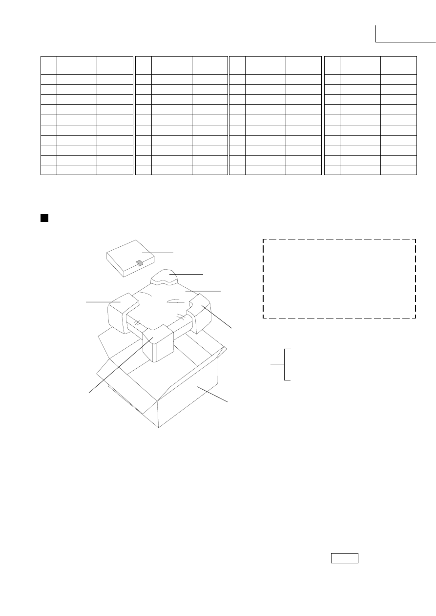
SA-EX310
Ref No.
Part No.
Values & Remarks
Packaging
(Refer to page 41 for the Parts List.)
Printed in Singapore
G970708000 P/T/O/J/N
MESA
*P3 (C)
P1
(RPG3462)
ACCESSORY
*P3 (B)
P2
(RPFX0005)
*P3 (D)
P3 (RPN0865)
*P3 (A) - Front Left
*P3 (B) - Front Right
*P3 (C) - Rear Left
*P3 (D) - Rear Right
*P3 (A)
A1 (EUR644377)
: REMOTE CONTROL UNIT
A2 (RJA0019-2K ...E, EG) : AC CORD
A2 (VJA0733 ...EB)
: AC CORD
A3 (RFKSEX310EK ... E)
: INSTR. MANUAL ASS'Y
A3 (RFKSEX310EBK ... EB) : INSTR. MANUAL ASS'Y
A3 (RFKSEX310EGK ... EG): INSTR. MANUAL ASS'Y
A4 (RSA0007)
: FM ANTENA
A5 (RSA0010)
: LOOP ANT UNIT
A6 (SJP9009 ... EB)
: ANT ADAPTER
A7 (SPSD152)
: ACCESSORY BOX
ACCESSORY
C1036
ECBT1H101KB5
100P
50V
[M]
C1037
ECBT1H101KB5
100P
50V
[M]
C1038
ECBT1H101KB5
100P
50V
[M]
C1039
ECEA1CU101B
100
16V
[M]
C1040
ECEA1CKA100B
10
16V
[M]
C1041
ECBT1E103ZF5
0.01
25V
[M]
C1051
ECA1HM2R2B
2.2
50V
[M]
C1052
ECA1HMR33B
0.33
50V
[M]
C1053
ECA1HM3R3B
3.3
50V
[M]
Ref No.
Part No.
Values & Remarks
Ref No.
Part No.
Values & Remarks
C1054
ECEA0JU221B
220
6.3V [M]
C1055
ECA1HMR47B
0.47
50V
[M]
C1056
ECQV1H823JZ3
0.082
50V
[M]
C1057
ECBT1C332KR5
3300P 16V
[M]
C1058
ECQV1H823JZ3
0.082
50V
[M]
C1059
ECEA1CU101B
100
16V
[M]
C1060
ECBT1E223ZF5
0.022
25V
[M]
C1062
ECBT1E223ZF5
0.022
25V
[M]
C1063
ECEA1CU101B
100
16V
[M]
C1065
ECBT1H681KB5
680P
50V
[M]
C1067
ECBT1C152KR5
1500P 16V
[M]
C1068
ECBT1C152KR5
1500P 16V
[M]
Ref No.
Part No.
Values & Remarks
Wyszukiwarka
Podobne podstrony:
Amplituner Technics SU V620
praca magisterska Strategia marketingowa firmy Tkaniny Techniczne SA w Pabianicach
Technics SA EH580 schematic
technics sa 424 sm [ET]
Amplituner Technics SU V620
TECHNICS SA DA20
Serwis Naukowo Techniczny PAP SA
Jakie umiejętności psychologiczne i socjologiczne są niezbędne w pracy technika bhp
Stopy żelaza są podstawowym tworzywem stosowanym we współczesnej technice
Przygotowane domowymi sposobami naturalne kosmetyki są łatwe do zrobienia, Technik Usług Kosmetyczny
STALE, Znaczenie techniczne mają stopy żelaza z węglem i innymi pierwiastkami Pierwiastki te są wpro
156 Rozporządzenie Ministra Spraw Wewnętrznych z dnia 13 11 2012 r w sprawie warunków technicznych p
Stale spawane wysokiej wytrzymałości są stosowane w dużych konstrukcjach spawanych o wysokim stopniu
Techniki badawcze są to pewne określone czynności badacza przyjęte w sposób świadomy w procedurze ba
Technical Support ar SA
NOTAKI Z TECHNIKI CYFROWEJ
techniki inchalacyjne
więcej podobnych podstron