Get More Power Out of
Dual or Quad Op-Amps
Although simple brute-force paralleling of op-amps is a bad
scheme for driving heavy loads, here is a good scheme for
dual op-amps. It is fairly efficient, and will not overheat if the
load is disconnected. It is not useful for driving active loads
or nonlinear loads, however.
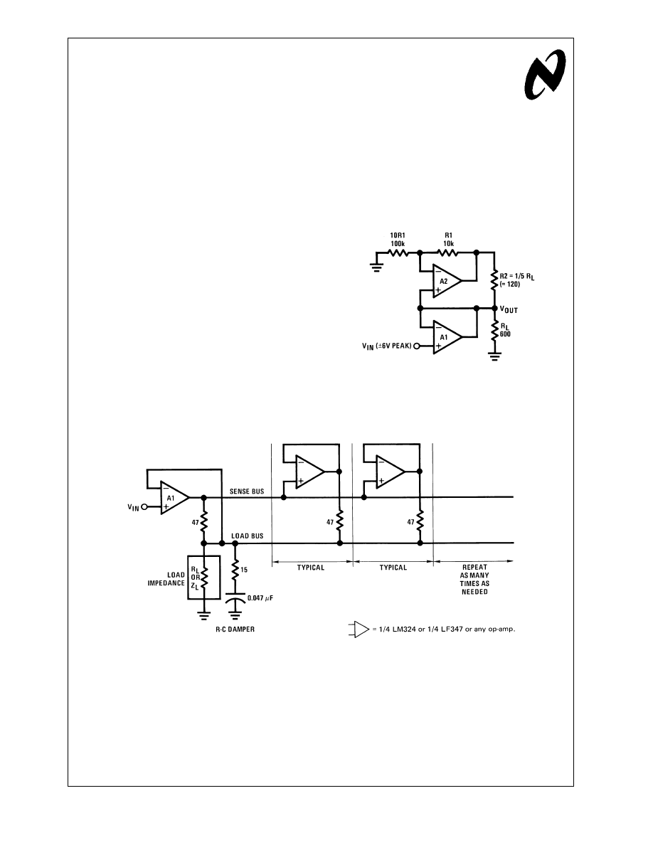
In Figure 1, an LF353N mini-DIP can drive a 600
Ω load to
±
9V typical (
±
6V min guaranteed) and will have only a 47˚C
temperature rise above free air. If the load R is removed, the
chip temperature will rise to +50˚C above free air. Note that
A2’s task is to drive half of the load. A1 could be applied as
a unity-gain follower or
inverter, or as a high-gain or
low-gain amplifier, integrator, etc.
While Figure 1 is suitable for sharing a load between 2
amplifiers, it is not suitable for 4 or more amplifiers, because
the circuit would tend to go out of control and overheat if the
load is disconnected.
Instead, Figure 2 is generally recommended, as it is capable
of driving large output currents into resistive, reactive, non-
linear, passive, or active loads. It is easily expandable to use
as many as 2 or 4 or 8 or 20 or more op-amps, for driving
heavier loads.
It operates, of course, on the principle that every op-amp has
to put out the same current as A1, whether that current is
plus, minus, or zero. Thus if the load is removed, all ampli-
fiers will be unloaded together. A quad op-amp can drive
600
Ω to
±
11 or 12 volts. Two quads can put out
±
40 mA, but
they get only a little warm. A series R-C damper of 15
Ω in
series with 0.047 µF is useful to prevent oscillations (al-
though LM324’s do not seem to need any R-C damper).
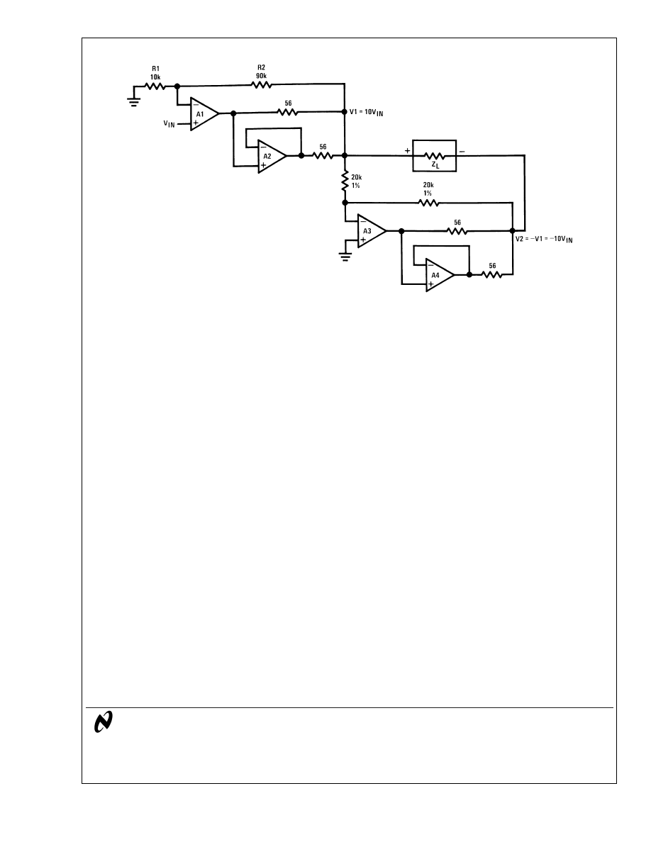
Of course, there is no requirement for the main amplifier to
run only as a unity-gain amplifier. In the example shown in
Figure 3, A1 amplifies a signal with a gain of +10. A2 helps it
drive the load. Then A3 operates as a unity-gain inverter to
provide V2 = −V1, and A4 helps it drive the load. This circuit
can drive a floating 2000
Ω load to
±
20V, accurately, using a
slow LM324 or a quick LF347.
00849301
A1, A2 = 1/2 LM747 or 1/2 LF353 or any op-amp.
FIGURE 1. A1 and A2 Share the Load
00849302
FIGURE 2. Improved Load-Sharing Circuit
National Semiconductor
Linear Brief 44
Bob Pease
April 1979
Get
More
Power
Out
of
Dual
or
Quad
Op-Amps
LB-44
© 2002 National Semiconductor Corporation
AN008493
www.national.com
LIFE SUPPORT POLICY
NATIONAL’S PRODUCTS ARE NOT AUTHORIZED FOR USE AS CRITICAL COMPONENTS IN LIFE SUPPORT
DEVICES OR SYSTEMS WITHOUT THE EXPRESS WRITTEN APPROVAL OF THE PRESIDENT AND GENERAL
COUNSEL OF NATIONAL SEMICONDUCTOR CORPORATION. As used herein:
1. Life support devices or systems are devices or
systems which, (a) are intended for surgical implant
into the body, or (b) support or sustain life, and
whose failure to perform when properly used in
accordance with instructions for use provided in the
labeling, can be reasonably expected to result in a
significant injury to the user.
2. A critical component is any component of a life
support device or system whose failure to perform
can be reasonably expected to cause the failure of
the life support device or system, or to affect its
safety or effectiveness.
National Semiconductor
Corporation
Americas
Email: support@nsc.com
National Semiconductor
Europe
Fax: +49 (0) 180-530 85 86
Email: europe.support@nsc.com
Deutsch Tel: +49 (0) 69 9508 6208
English
Tel: +44 (0) 870 24 0 2171
Français Tel: +33 (0) 1 41 91 8790
National Semiconductor
Asia Pacific Customer
Response Group
Tel: 65-2544466
Fax: 65-2504466
Email: ap.support@nsc.com
National Semiconductor
Japan Ltd.
Tel: 81-3-5639-7560
Fax: 81-3-5639-7507
www.national.com
00849303
FIGURE 3. Typical Application of Load-Sharing
LB-44
Get
More
Power
Out
of
Dual
or
Quad
Op-Amps
National does not assume any responsibility for use of any circuitry described, no circuit patent licenses are implied and National reserves the right at any time without notice to change said circuitry and specifications.
Document Outline
Wyszukiwarka
Podobne podstrony:
cw 44
44 OBIEKTY INż KOMUNALNEJ sem VI S1 KBI
43 44
44
02 01 11 11 01 44 an kol2 1 7id 3881
02 1995 43 44
44 47 407 pol ed02 2005
2015 08 20 07 44 48 01
44 rozp uznawanie kwalifikacji zaw egulowanych
44 Cele i struktura planu marketingowego
R 44, A T e o r i a S p r ę ż y s t o ś c i, T E M A T Y B L O K O W E, XIV Stateczność preta pro
wymagania egzaminacyjne - 44, Anatomia, wymagania egzaminacyjne
44 System klanowo totemiczny, kulturoznawstwo
44, Prawo, WZORY PISM, Wzory Pism 2
44
Matsumoto str 16 44
sciąga ŁB
więcej podobnych podstron