Page: 1
Service Guide OL840
Chapter 0 About This Manual
OL840
LED Page Printer
Adobe Acrobat printable reference
copy of the OKIDATA Service Training Manual.
09/17/97
Note: This Adobe Acrobat version of the Okidata Service Training Manual was built with the
pictures rendered at 300 dpi, which is ideal for printing, but does not view on most
displays well.
Copyright 1997, Okidata, Division of OKI America, Inc. All rights reserved. See the OKIDATA Business
Partner Exchange (BPX) for any updates to this material. (http://bpx.okidata.com)

Table of Contents
Page
Service Guide OL840
0 About This Manual
Front Cover
1
Copyright
2
Manual Revision
3
1 Product Specifications
1.1 Overview
4
1.2 Product Specifications
5
1.3 Paper Specifications
6
1.4 Physical Specifications
7
1.5 Power Requirements
8
1.6 Environmental Conditions
9
1.7 Agency Approvals
10
2 Principles of Operation
2.1 Overview
11
2.2 Printer Overview
12
....2.2.02 Main Control Unit
13
....2.2.03 Main Controller Board (RPSS)
14
....2.2.04 Program ROM Board (RPSR)
15
....2.2.05 Connection Board (LNKZ)
16
....2.2.06 Expansion RAM Board (REXM)
17
....2.2.07 Font Card
18
2.3 Printer Control Unit
19
....2.3.02 Engine Driver Board (LLAB-2)
20
....2.3.03 Power Supply Unit
21
....2.3.04 Fuser Unit
22
....2.3.05 Main Motor (Drum Motor)
23
....2.3.06 LED Array
24
....2.3.07 Resist Motor
25
....2.3.08 DC Fan
26
....2.3.09 Operation Panel
27
....2.3.10 Second Paper Tray Mechanism (Option)
28
....2.3.11 Sensor Functions
29
3 Maintenance & Disassembly
3.1 Maintenance
30
....3.1.02 Maintenance Tools
31
....3.1.03 Maintenance Precautions
32
3.2 Disassembly/Assembly Procedures
33
....Sequence of Procedures
34
....3.2.01 Main Controller Board (RPSS)
35
....3.2.02 Program ROM Board (RPSR)
36
....3.2.03 Optional Expansion RAM Board (REXM)
37
3.3 Adjustments And Service Checks
38

Table of Contents
Page
3.4 Cleaning
39
3.5 Lubrication
40
3.6 Consumables
41
4 Failure & Repair Analysis
4.1 OL840 Troubleshooting
42
....4.1.02 LCD Display Messages (PostScript Mode)
43
A Reference Charts
A.1 Overview
44
A.2 Charts
45
....A.2.01 Main Control Board (RPSS)
46
....A.2.02 Program ROM Board (RPSR)
47
....A.2.03 RAM Board (REXM) (Option)
48
B Illustrated Parts Listing
Ol800/Ol820/Ol840 Parts Compatibility List
49
....Interchangeable Parts (OL800, OL820 and OL840)
50

Page: 2
Service Guide OL840
Chapter 0 About This Manual
This document may not be reproduced without written permission of the Okidata® Technical
Training Group. Every effort has been made to ensure the accuracy of the information contained
in this training course. Okidata is not responsible for errors beyond its control.
© 1994 by Okidata All rights reserved.
First Edition, March 1992
Second Edition May, 1994
Written and produced by the Okidata Technical Training Group
Please address any comments on this publication to:
Technical Training Group
Okidata
532 Fellowship Road
Mount Laurel, NJ 08054-3499
Fax Number: (609) 235-2600, ext. 7034
Okilink Login Name: Technical Training
OKIDATA is a registered trademark of Oki Electric Industry Company, Ltd.; Marque deposee de
Oki Electric Industry Company, Ltd.; Marca Registrada, Oki Electric Industry Company, Ltd.
BAR CODES PLUS, MICRO DOCS and OKIPRO 65 are trademarks of OKIDATA, Division of OKI
America, Inc.
Adobe, Adobe Illustrator, and PostScript are registered trademarks of Adobe Systems
Incorporated.
Apple, AppleTalk, LaserWriter, LaserWriter II, LocalTalk, and Macintosh, are registered
trademarks of Apple Computer, Incorporated.
Bitstream is a registered trademark and Dutch, Fontware, and Swiss are trademarks of Bitstream,
Inc. Fontware is licensed to Bitstream, Inc., in West Germany, France, and the United Kingdom by
Electronic Printing Systems, Ltd.
Diablo 630 is a registered trademark of Xerox Corporation.
Helvetica, Optima, Palatino, Present and Times are registered trademarks of Linotype AG and/or
its subsidiaries.

Hewlett-Packard, HP, LaserJet, and LaserJet Series II are registered trademarks of
Hewlett-Packard Company.
IBM, PC, PC-DOS, and Proprinter XL are registered trademarks of International Business
Machines Corporation.
Copyright 1997, Okidata, Division of OKI America, Inc. All rights reserved. See the OKIDATA Business
Partner Exchange (BPX) for any updates to this material. (http://bpx.okidata.com)

Page: 3
Service Guide OL840
Chapter 0 About This Manual
Note: The OL800/820 Service Training course is part of the OL-Series Training
Course and can not be purchased separately.
© 1994 by Okidata All rights reserved.
First Edition, March 1992
Second Edition May, 1994
Written and produced by the Okidata Technical Training Group
THE OL400/800/820/830/840 VIDEO TRAINING KIT covers the following
products:
o OL400
o OL800
o OL820
o OL830
o OL840
The following items are included in the kit:
o OL400 Service Handbook
o OL800/820 Service Handbook
o OL830 Service Handbook
o OL840 Service Handbook
o Service Training Video
o OL400/800/820 User's Documentation
o OL830 User's Documentation
o OL840 User's Documentation
Price: $95.00 ($124.00 Canadian)
P/N 58226902
Copyright 1997, Okidata, Division of OKI America, Inc. All rights reserved. See the OKIDATA Business
Partner Exchange (BPX) for any updates to this material. (http://bpx.okidata.com)

Page: 4
Service Guide OL840
Chapter 1 Product Specifications
1.1
OVERVIEW
1.1.01 General Information
The OL840 is an 8 page per minute page printer, with true Adobe Postscript capability. The
OL840 uses a stationary LED head and dry electrophotography as its exposure and development
methods.
In addition to supporting Adobe Postscript (35 Fonts), the OL840 provides two additional
emulations. The HP Laserjet Series II emulation has 36 resident fonts. The Diablo 630 emulation
has 18 resident fonts. Two optional font cards can be installed with the Diablo and HP emulations.
Six cards are available at this time. The OL840 also accepts HP compatible downloadable fonts.
A 2MB page memory is standard on the OL840; this can be expanded to 4MB with an optional
RAM printed circuit board.
A Centronics parallel interface, an RS-232C serial interface and an AppleTalk interface are
standard.
Two consumables are used in the printer. The toner cartridge kit contains a toner cartridge, a
fuser cleaner pad, and an LED lens cleaner. The other consumable, the image drum cartridge kit,
includes an image drum cartridge and an ozone filter. Toner and drum life depend on printer use.
Based on a 5% print density and 10 pages per job, a toner cartridge should last approximately
2,500 pages; a drum should last approximately 15,000 pages.
A 200 sheet letter-size paper tray is included with the printer, and a second tray can be added,
providing an additional 200 pages. Legal, Envelope, Executive and A4 paper trays are also
available. Paper feeding can be done automatically or manually. Pages can be printed face-down
or face-up. A rear exit path is provided for items such as: card stock, envelopes, labels or
overhead transparencies.
An OL800 may be upgraded to an OL840 by removing the Program Cartridge and replacing the
Main Controller Board with the Postscript Controller Board.
The OL840 Printer is a member of the family of OL Series Printers which presently includes the
OL400, OL800, OL820 and OL830. Okidata's own proprietary engine assures built-in quality and
reliability.
Copyright 1997, Okidata, Division of OKI America, Inc. All rights reserved. See the OKIDATA Business
Partner Exchange (BPX) for any updates to this material. (http://bpx.okidata.com)

Page: 5
Service Guide OL840
Chapter 1 Product Specifications
1.2
PRODUCT SPECIFICATIONS
1.2.01 Print Specifications
Development method: Dry electrophotography
Exposure method: Stationary LED head
1.2.02 Print Speed
First print: 28 seconds maximum (letter size)
Continuous print: 8 sheets/minute (letter size)
Warm-up time: 40 seconds maximum [at room temperature 77oF (25oC) and rated voltage
(120 VAC)] Postscript Initialization time: 120 seconds maximum [with 4 MB memory installed
and "Do Start Page" deselected]
1.2.03 Symbol Sets
HP Emulation:
Thirty-nine symbol sets are available through the OL840.
1.2.04 Available Fonts
Postscript: 35 Adobe Fonts
HP Emulation: 36 resident fonts (HP A,B,C,F,L,Y,S1 and S2 Cartridge Fonts)
Diablo 630 Emulation: 18 resident fonts
1.2.05 Paper Feed Method
Automatic feed
Manual Feed
1.2.06 Paper Delivery Method
Face down/face up
1.2.07 Print Resolution
300 x 300 dots/inch
1.2.01 Print Specifications
Development method: Dry electrophotography
Exposure method: Stationary LED head
1.2.02 Print Speed

First print: 28 seconds maximum (letter size)
Continuous print: 8 sheets/minute (letter size)
Warm-up time: 40 seconds maximum [at room temperature 77oF (25oC) and rated voltage (120
VAC)]
Postscript Initialization time: 120 seconds maximum [with 4 MB memory installed and "Do Start
Page" deselected]
1.2.03 Symbol Sets
HP Emulation:
Thirty-nine symbol sets are available through the OL840.
1.2.04 Available Fonts
Postscript: 35 Adobe Fonts
HP Emulation: 36 resident fonts (HP A,B,C,F,L,Y,S1 and S2 Cartridge Fonts)
Diablo 630 Emulation: 18 resident fonts
1.2.05 Paper Feed Method
Automatic feed
Manual Feed
1.2.06 Paper Delivery Method
Face down/face up
1.2.07 Print Resolution
300 x 300 dots/inch
Copyright 1997, Okidata, Division of OKI America, Inc. All rights reserved. See the OKIDATA Business
Partner Exchange (BPX) for any updates to this material. (http://bpx.okidata.com)

Page: 6
Service Guide OL840
Chapter 1 Product Specifications
1.3
PAPER SPECIFICATIONS
1.3.01 Paper Types
Letter
Size: 8.5" x 11"
Feed: Automatic or Manual
Weight: Minimum 16 lbs
Maximum 24 lbs
Recommended 20 lbs
Legal
Size: 8.5" x 14"
Feed: Automatic (with optional paper tray) or Manual
Weight: Minimum 16 lbs
Maximum 24 lbs
Recommended 20 lbs
Executive
Size:7.25" x 10.5"
Feed: Automatic (with optional paper tray) or Manual
Weight: Minimum 16 lbs
Maximum 24 lbs
Recommended 20 lbs
A4
Size:8.27" x 11.69"
Feed: Automatic (with optional paper tray) or Manual
Weight: Minimum 16 lbs
Maximum 24 lbs
Recommended 20 lbs
Envelopes
Size:Minimum 3.5" x 7.5"
Maximum 7.2" x 10.1"
Feed: Automatic (with optional paper tray) or Manual
Weight: Minimum 16 lbs
Maximum 24 lbs
Recommended 20 lbs
Labels - Manual feed / Face up delivery only
Use labels designed specifically for laser printers.
Transparencies - Manual feed / Face up delivery only
Must be able to withstand the heat of the fusing process.
CAUTION:

Envelopes, labels, and transparencies should only be fed from the top paper tray.
Copyright 1997, Okidata, Division of OKI America, Inc. All rights reserved. See the OKIDATA Business
Partner Exchange (BPX) for any updates to this material. (http://bpx.okidata.com)

Page: 7
Service Guide OL840
Chapter 1 Product Specifications
1.4
PHYSICAL SPECIFICATIONS
1.4.01 Outside Dimensions
Width: 17.72"
Height:9.49"
Length: 17.72"
1.4.02 Printer Weight
37 lbs.
1.4.03 LED Array
Number of LED Elements - 2560
Copyright 1997, Okidata, Division of OKI America, Inc. All rights reserved. See the OKIDATA Business
Partner Exchange (BPX) for any updates to this material. (http://bpx.okidata.com)

Page: 8
Service Guide OL840
Chapter 1 Product Specifications
1.5
POWER REQUIREMENTS
1.5.01 Input Power
120 VAC +5.5%, -15%
220/240 VAC +/-10%
1.5.02 Power Consumption
Approximately 800 W maximum during operation
Copyright 1997, Okidata, Division of OKI America, Inc. All rights reserved. See the OKIDATA Business
Partner Exchange (BPX) for any updates to this material. (http://bpx.okidata.com)

Page: 9
Service Guide OL840
Chapter 1 Product Specifications
1.6
ENVIRONMENTAL CONDITIONS
1.6.01 Ambient Temperature and Relative Humidity
Operation
50° to 89° F
10° to 32° C
20 to 80% Relative Humidity
Storage
14° to 122° F
10° to 50° C
1.6.02 Printer Noise Level
During operation: 50 dB maximum
At standby: 43 dB maximum
Copyright 1997, Okidata, Division of OKI America, Inc. All rights reserved. See the OKIDATA Business
Partner Exchange (BPX) for any updates to this material. (http://bpx.okidata.com)

Page: 10
Service Guide OL840
Chapter 1 Product Specifications
1.7
AGENCY APPROVALS
FCC Class B
UL 478 Ver.5
CSA 22.2 220
Copyright 1997, Okidata, Division of OKI America, Inc. All rights reserved. See the OKIDATA Business
Partner Exchange (BPX) for any updates to this material. (http://bpx.okidata.com)

Page: 11
Service Guide OL840
Chapter 2 Principles of Operation
2.1 OVERVIEW
2.1.01 Outline of Printer Operation
The primary control boards of the printer are the Engine Driver Board (LLAB-2) and the Main
Controller Board (RPSS). The Engine Driver Board controls the printer mechanism and drives the
LED head. The Main Controller Board receives data from the host device, analyzes commands,
and processes the data for printing. To help you understand the structure of the printer system,
refer to the Printer Block Diagram.
The RPSS PCB is connected to the host system through a Centronics parallel interface, RS-232C
interface or an AppleTalk interface. Interface selection is accomplished through menu settings.
Once an interface is selected, the remaining interface connectors output BUSY (Emulation Mode
only). The Main Controller Board receives print data and command strings from the host system,
and generates bit image data. When one page of print data is ready, the Main Controller Board
turns on the PRINT-N signal which is one of the video interface signals. Upon receipt of the
PRINT-N signal, the Engine Driver Board turns ON the main motor, resist motor, and fuser in
preparation for printing. The Engine Driver Board then sends the FSYNC-N and LSYNC-N signals
to the Main Controller Board.
Once the Main Controller Board receives the FSYNC-N and LSYNC-N signals, the WDATA-N
signal (image data signal) is sent to the Engine Driver Board in synchronization with the WCLK-N
signal. The Engine Driver Board turns ON the appropriate LEDs in conformance with the
WDATA-N signal.
In addition to the above, the Engine Driver Board controls the paper feed, paper transport, and
xerographic processing actions necessary for printing.
The Operation Panel is connected to the Main Controller Board via the LLCC PCB, the Engine
Driver Board and the LNKZ PCB. The Operation Panel is controlled by the Main Controller Board.
The optional Second Paper Tray (LLFC PCB) is controlled by the Engine Driver Board.
The Main Controller Board contains 2 MByte of dynamic RAM. The Expansion Memory Board
(REXM) provides an additional 2 Mbyte of dynamic RAM.
Two font cards slots are available. Each font card contains ROM which provides additional fonts.
The two connectors for the font cards are provided on the CMBZ PCB. The font card data is sent
to the Main Controller Board through the LNKZ PCB.
Copyright 1997, Okidata, Division of OKI America, Inc. All rights reserved. See the OKIDATA Business
Partner Exchange (BPX) for any updates to this material. (http://bpx.okidata.com)

Page: 12
Service Guide OL840
Chapter 2 Principles of Operation
2.2 PRINTER OVERVIEW
2.2.01 General Information
This section describes the operation of the OL840 Printer in the following order:
· Main Control Function
· Printer Control Function
· Mechanical Operation
· Sensors and Switches
Copyright 1997, Okidata, Division of OKI America, Inc. All rights reserved. See the OKIDATA Business
Partner Exchange (BPX) for any updates to this material. (http://bpx.okidata.com)

Page: 13
Service Guide OL840
Chapter 2 Principles of Operation
2.2.02 Main Control Unit
The control unit controls reception of the data from the host through the interface, processes
command analysis, bit image development, and raster buffer read. It also controls signal flow with
the Engine Driver Board and the Operator Panel.
Reception Control
The control unit has three interface ports: centronics parallel, RS-232C serial, and
Appletalk/RS-422 serial ports. Through the MENU, one of the I/F ports can be selected at a time.
The other ports output BUSY in emulation mode, but not in PostScript mode. The Appletalk port is
the default port.
Command Analysis Processing
The OL840 has PostScript and the following emulation modes which are selected through the
printer MENU:
· LaserJet Series II: Hewlett Packard
· Diablo 630: Xerox
In the Postscript mode, each typeface style is stored as a series of outlines, one for each
character, comprised of lines and Bezier curves. The shape of each character in a typeface style
is actually determined by a mathematical formula. When the document is to be printed, the host
sends information to the printer in the form of the Postscript page description language. The
printer then reads the file it receives, sizes and orients each character outline as required, and
prints the page.
In the HP and Diablo modes, the OL840 prints fonts as bit-mapped outlines. The outline of each
character is determined by placing dots in a grid. A complete set of these grids, one for each
character in the font, is stored in ROM. Since no special calculations are used in the HP mode,
each typeface, style, weight, orientation and size is stored separately.
Down Line Loaded (DLL) fonts and macro registration are stored in the DLL and macro areas of
memory (RAM) Emulation and Postscript interpretation is performed under program control by the
CPU.
Font Processing
In the emulation mode, the bit image in the font ROM is loaded by the CPU into the raster buffer
(RAM). The raster buffer has a band buffer structure, new data is written to the raster buffer once
the buffer has been read and becomes empty.
In Postscript mode, the outline data stored in the programmed ROM is loaded into the RAM area
called the font cache, the required font pattern is then transferred to the raster buffer. The buffer
has a full-page buffer structure. One page of data is written at a time. After a page is written,
another raster buffer read operation starts.
Raster Buffer Read Operation
The bit image written to the raster buffer by the CPU is converted to serial dot data to be read in

response to the VIDEO SYNCH signal.
The first in-first out (FIFO) buffer is between the raster buffer and the serial dot data of the video
interface (WDATA).
The CPU can transfer data from the raster buffer to the FIFO automatically when the CPU reads
the "OR-ING" memory area of the raster buffer. The CPU reads a line of data from the raster
buffer before the LSYNC signal is received from the Engine Driver Board.
Once LSYNC is received, reading starts. Then, in response to WCLK, parallel to serial conversion
and data transfer takes place.
The amount of data that is read from the FIFO is sensed by the 64NC22VIA counter. The CPU
writes another line of data to the FIFO, immediately after a line of data is read from the FIFO.
Engine I/F Processing
The engine I/F is divided into the engine control interface and the command interface. The engine
control interface signal is allocated to a signal line through bits of the register (TTL). The CPU can
obtain the engine status by sensing each bit, or run the engine by manipulating each bit.
The command I/F is a bidirectional serial signal. The register (TTL) is used for serial-parallel or
parallel-serial conversion.
Operation Panel Control
The operation panel I/F is a bidirectional serial Interface. Each signal line is allocated to the
65NC22VIA port. The CPU then sends the shift clock and executes serial or serial-parallel
conversion.
Copyright 1997, Okidata, Division of OKI America, Inc. All rights reserved. See the OKIDATA Business
Partner Exchange (BPX) for any updates to this material. (http://bpx.okidata.com)

Page: 14
Service Guide OL840
Chapter 2 Principles of Operation
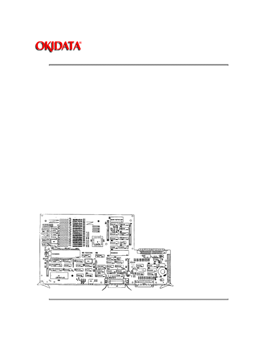
2.2.03 Main Controller Board (RPSS)
The Main Controller Board (RPSS) can be accessed from the rear of the printer. The RPSS board
consists of the CPU, RAM, VIA, FIFO, SCC, and one gate array.
The CPU is a MC68000 with a clock frequency of 12.5MHz.
Sixteen 1Mbit (1 bit x 1Mbit) dynamic RAM chips are mounted as resident RAM (total 2Mbytes).
The VIA (Versatile Interface Adapter) ICO6G (65NC22) controls the Operation Panel interface,
Printer Unit interface, read/write operations of FIFO (IC14G) and the EEPROM IC05H (X24C16).
The FIFO (First in-First out Buffer) connects the CPU to the video interface. The FIFO has a
capacity of over 2 lines (2 rasters). The data written to the FIFO by the CPU is sequentially read
according to the VIDEO I/F synchronous signal.
The Serial Communications Controller (SCC) controls the RS-232C interface, RS-422 interface,
and the AppleTalk interface. The RS-422 and AppleTalk interfaces use the same connector and
are usable only in the PostScript mode.
Copyright 1997, Okidata, Division of OKI America, Inc. All rights reserved. See the OKIDATA Business
Partner Exchange (BPX) for any updates to this material. (http://bpx.okidata.com)

Page: 15
Service Guide OL840
Chapter 2 Principles of Operation
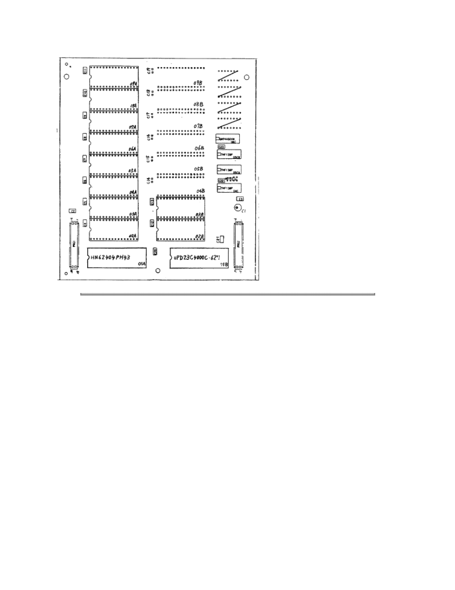
2.2.04 Program ROM Board (RPSR)
The Program ROM (RPSR) Board is connected to the Main Controller Board. The RPSR board
consists of:
· Ten 1 Mbit EPROM chips (eight are for PostScript - two are for Emulation Mode)
· Two 4 Mbit MASK ROM chips which store the bit-map fonts used in HP Laserjet and
Diablo emulations
· Three TTL IC chips, which function as an address decoder.
Copyright 1997, Okidata, Division of OKI America, Inc. All rights reserved. See the OKIDATA Business
Partner Exchange (BPX) for any updates to this material. (http://bpx.okidata.com)

Page: 16
Service Guide OL840
Chapter 2 Principles of Operation
2.2.05 Connection Board (LNKZ)
The LNKZ connection board contains a buffer used to connect the optional font cards to the Main
Controller Board.
Copyright 1997, Okidata, Division of OKI America, Inc. All rights reserved. See the OKIDATA Business
Partner Exchange (BPX) for any updates to this material. (http://bpx.okidata.com)

Page: 17
Service Guide OL840
Chapter 2 Principles of Operation
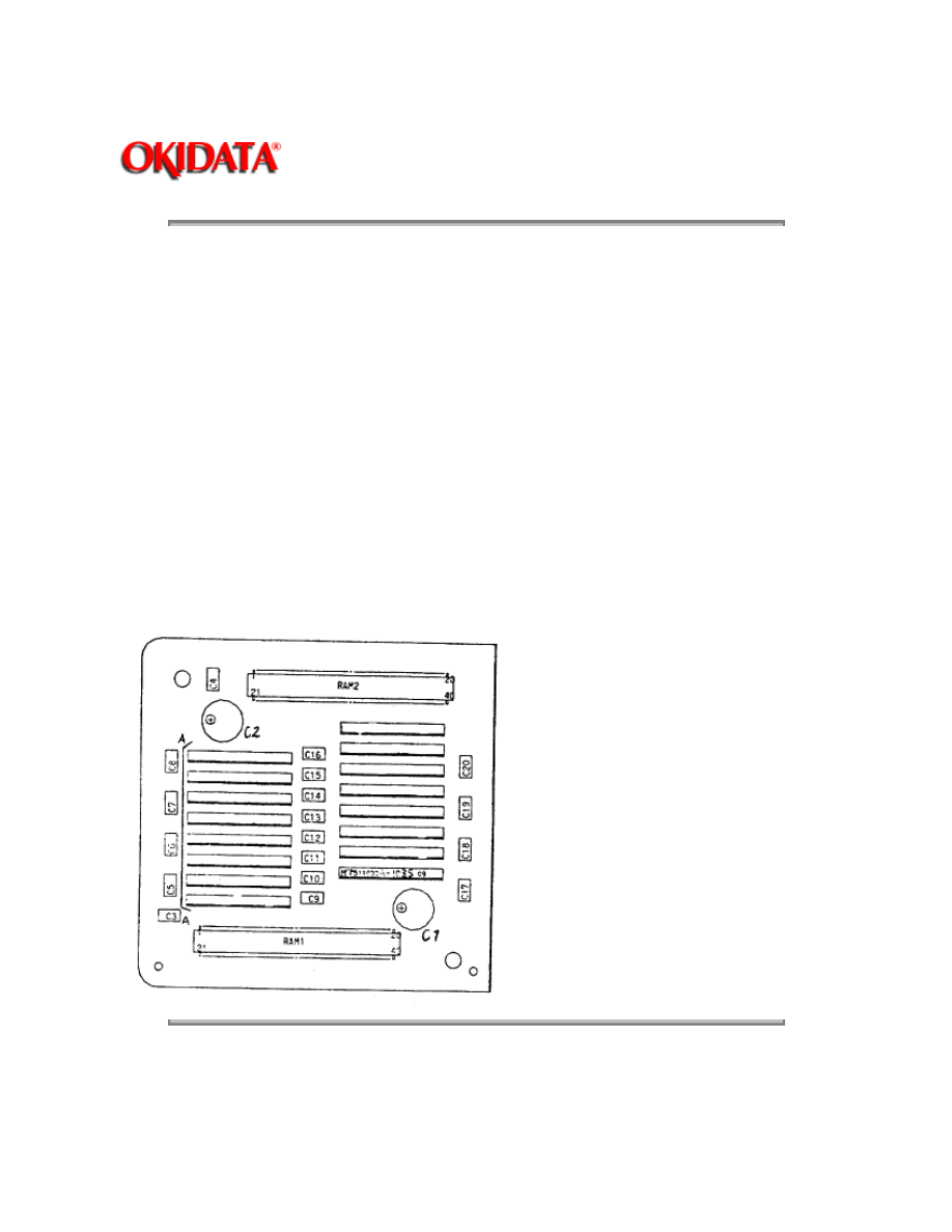
2.2.06 Expansion RAM Board (REXM)
Sixteen 1Mbit (1bit x 1Mbit) dynamic RAM (total 2M bytes) are mounted to the Expansion RAM
Board. The RAM capacity is detected during the power-on sequence. The RAM capacity is printed
during
MENU PRINT
in the Emulation Mode or
START PAGE
in Postscript mode.
Copyright 1997, Okidata, Division of OKI America, Inc. All rights reserved. See the OKIDATA Business
Partner Exchange (BPX) for any updates to this material. (http://bpx.okidata.com)

Page: 18
Service Guide OL840
Chapter 2 Principles of Operation
2.2.07 Font Card
Up to two font cards for additional fonts can be installed. If the printer is in the off-line state (the
READY lamp is off), the cards can be inserted and removed without removing power. When the
font card is inserted and removed in the on-line state (the READY lamp is on), the message,
CARD REMOVED ONLINE
, will be displayed on the Operation Panel.
Copyright 1997, Okidata, Division of OKI America, Inc. All rights reserved. See the OKIDATA Business
Partner Exchange (BPX) for any updates to this material. (http://bpx.okidata.com)

Page: 19
Service Guide OL840
Chapter 2 Principles of Operation
2.3 PRINTER CONTROL UNIT
2.3.01 General Information
The principal hardware components of the printer control unit are listed below.
· Engine Board
· Power Supply Unit
· Fuser Unit
· Main Motor
· LED Head
· Sensors and Switches
· Resist Motor
· Fan
· Operation Panel
· Second Paper Tray Mechanism (option)
Copyright 1997, Okidata, Division of OKI America, Inc. All rights reserved. See the OKIDATA Business
Partner Exchange (BPX) for any updates to this material. (http://bpx.okidata.com)

Page: 20
Service Guide OL840
Chapter 2 Principles of Operation
2.3.02 Engine Driver Board (LLAB-2)
The Engine Driver Board contains an 80C51 Microprocessor (8-bit), an EPROM which stores the
Engine Control Program and an EEPROM.
The Engine Driver Board turns the LED Array diodes ON, to place an electrostatic image on the
photosensitive drum. The Engine Driver Board also controls the paper feed, paper transport, and
electrophotographic processing actions so that the electrostatic image can be printed by fusing
toner on the paper.
The 1-Kbit Electrically Erasable PROM (EEPROM) is loaded with the data listed below.
· Total number of sheets printed after installation
· Modified page count
· Total number of sheets printed with the current drum
· Total number of sheets printed with the current fuser
· Setting of time required from the completion of printing to Quiet Mode
· Feed time needed to feed the paper to a printable position
· Vertical Registration (Top margin)
· LED head drive time
Notes:
The EEPROM preserves the data while the supply voltage is off.
The counters stored in the EEPROM can be accessed by using SW1 on the Engine Board to
place the printer in the Maintenance MODE. (See Section 3)
The count of the total number of sheets printed after installation cannot be reset.
The count of the total number of sheets printed with the drum currently in use should be taken as
a rough measure of the useful life of the drum: It is reset to zero when the drum is replaced by
holding down the RESET button and applying power to the printer.
Copyright 1997, Okidata, Division of OKI America, Inc. All rights reserved. See the OKIDATA Business
Partner Exchange (BPX) for any updates to this material. (http://bpx.okidata.com)

Page: 21
Service Guide OL840
Chapter 2 Principles of Operation
2.3.03 Power Supply Unit
The power supply unit generates the following voltages from the AC input voltage:
High Voltage Drive
The high-voltage circuit provides the charge voltage (about -6 Kvdc), transfer voltage (about +5
Kvdc), grid voltage (about -600vdc), and developer bias voltages (about -550vdc and -400vdc). Of
these voltages, the charge voltage and the transfer voltage are generated by a high-voltage power
supply. The grid connects to ground via a varistor on the medium-voltage generation circuit. This
keeps the grid at about -680vdc during charging.
Low Voltage Circuit
This circuitry produces the voltages listed below.
· +5 vdc: Printer Logic
· +/- 12 vdc: Interface Signal Levels
· +38 vdc: Resist/Main Motor Drive, Fan Drive
Note:
+5 vdc and +38 vdc are also supplied to the LLFC on the 2nd Paper Tray Mechanism
Copyright 1997, Okidata, Division of OKI America, Inc. All rights reserved. See the OKIDATA Business
Partner Exchange (BPX) for any updates to this material. (http://bpx.okidata.com)

Page: 22
Service Guide OL840
Chapter 2 Principles of Operation
2.3.04 Fuser Unit
The Fuser Unit is controlled by a thermistor, a comparator, an LSI, and the CPU to keep the heat
roller surface temperature within a predetermined range (about 150 degrees Celsius). A thermal
fuse within the Fuser Unit prevents abnormal temperature rises in case the thermistor fails.
Note:
The CPU checks for an open circuit in the thermistor at power -on, setting a fuser alarm if
this error is detected.
The CPU also sets a fuser alarm if the proper temperature is not attained within a
specified period of time after power-on.
Upon detecting a fuser alarm, the CPU will halt (after printing the current page.)
Copyright 1997, Okidata, Division of OKI America, Inc. All rights reserved. See the OKIDATA Business
Partner Exchange (BPX) for any updates to this material. (http://bpx.okidata.com)

Page: 23
Service Guide OL840
Chapter 2 Principles of Operation
2.3.05 Main Motor (Drum Motor)
The Main Motor is controlled by the motor control LSI, IC5 (M54646). The motor used is a
four-phase motor, driven by the DM-PHL 1, 2, 3 and 4 signals generated by the LSI.
Copyright 1997, Okidata, Division of OKI America, Inc. All rights reserved. See the OKIDATA Business
Partner Exchange (BPX) for any updates to this material. (http://bpx.okidata.com)

Page: 24
Service Guide OL840
Chapter 2 Principles of Operation
2.3.06 LED Array
Data for the 2,560 LEDs in the LED Array is placed in the shift register by the HD CLK signal. The
data is loaded in the latch circuit by the HD LD signal.
Copyright 1997, Okidata, Division of OKI America, Inc. All rights reserved. See the OKIDATA Business
Partner Exchange (BPX) for any updates to this material. (http://bpx.okidata.com)

Page: 25
Service Guide OL840
Chapter 2 Principles of Operation
2.3.07 Resist Motor
The Resist Motor is driven clockwise for hopping, then counterclockwise for Paper Feeding by the
motor drive IC (LB1731).
Copyright 1997, Okidata, Division of OKI America, Inc. All rights reserved. See the OKIDATA Business
Partner Exchange (BPX) for any updates to this material. (http://bpx.okidata.com)

Page: 26
Service Guide OL840
Chapter 2 Principles of Operation
2.3.08 DC Fan
The fan is controlled by the FAN ON-P signal from the LSI (MSM73H019). In order for the printer
to operate, the signal FAN SENSE-N must be active.
Note:
The fuser and the fan are not enabled when the cover is open. If the fan fails to run, the fuser will
turn off and FAN ALARM is set. Printing is disabled.
In accordance with the TIME TO QUIET setting of the level 2 Menu, the Fuser will maintain the
proper fusing temperature for 1 or 8 minutes after the last page has been printed. If printing is not
requested within the selected time frame, the fuser will turn OFF and the fan speed will be
reduced 50%. Selecting DISABLE allows the FUSER to maintain the proper fusing temperature
continuously.
Copyright 1997, Okidata, Division of OKI America, Inc. All rights reserved. See the OKIDATA Business
Partner Exchange (BPX) for any updates to this material. (http://bpx.okidata.com)

Page: 27
Service Guide OL840
Chapter 2 Principles of Operation
2.3.09 Operation Panel
The following components make up the operation panel:
· 4-bit MPU (LC6543C)
· LCD control driver (MSM6222B or HD44780)
· LCD display (16 characters per line)
· Operation panel sheet
· LEDs (for online mode indication)
Operation Buttons
The Operation Panel is connected to the Main Controller Board via the Engine Connection Board,
the Engine Driver Board and the Program Cartridge Connection Board. The Operation Panel is
controlled by the Main Controller Board.
The LCD control driver (MSM622B or HD44780) converts 4-bit character codes received from the
MPU into 8-bit character codes and retrieves the character pattern data (font) from the internal
character generator for display on the LCD.
Operation Panel Interface
The operation panel is controlled by the operation panel interface located on the Main Controller
Board. Control is via the Engine Driver Board.
Copyright 1997, Okidata, Division of OKI America, Inc. All rights reserved. See the OKIDATA Business
Partner Exchange (BPX) for any updates to this material. (http://bpx.okidata.com)

Page: 28
Service Guide OL840
Chapter 2 Principles of Operation
2.3.10 Second Paper Tray Mechanism (Option)
The Second Paper Tray Mechanism is controlled by the Second Tray Driver Board (LLFC). This
board is attached to the left side of the second paper tray mechanism. The resist motor and paper
tray detection sensors for the second paper tray are mounted on this board.
Copyright 1997, Okidata, Division of OKI America, Inc. All rights reserved. See the OKIDATA Business
Partner Exchange (BPX) for any updates to this material. (http://bpx.okidata.com)

Page: 29
Service Guide OL840
Chapter 2 Principles of Operation
2.3.11 Sensor Functions
The following alarms are detected by sensors and switches.
During Power ON
The inlet and outlet sensors are checked for their on and off states at power on time.
· Inlet sensor on: Inlet jam error (paper supply jam)
· Outlet sensor on: Outlet jam error (paper eject jam)
The thermistor sensor detects if the fuser temperature reaches the desired temperature within the
specified time. If the desired temperature is not reached, the fuser is turned
OFF
.
The fan sensor circuitry checks for the rotation of the fan. If fan motion is not detected, the fuser is
turned
OFF
, and power is removed from the fan.
When a paper cassette with no paper loaded has been detected, the Paper-End Sensor sends the
PAPER END
signal to the Control Unit.
When the power supply is turned
ON
, the number of printed pages of the fusing unit and drum
cartridge is checked. If the Fuser or Drum life has been exceeded, this information is transmitted
to the Control Unit.
During Hopping
Whenever the inlet sensor fails to detect paper within a predetermined time after a feed command
has been issued to the paper supply system, the failure is counted. The hopping operation is then
attempted up to three times. If the hopping operation still fails, an
INLET JAM ERROR
is displayed
on the Operation Panel.
During Feeding
If the leading part of the paper does not reach the outlet sensor within a predetermined time after
the start of feeding by the resist motor, a
FEED JAM ERROR
will be displayed on the Operation
Panel.
Copyright 1997, Okidata, Division of OKI America, Inc. All rights reserved. See the OKIDATA Business
Partner Exchange (BPX) for any updates to this material. (http://bpx.okidata.com)

Page: 30
Service Guide OL840
Chapter 3 Maintenance & Disassembly
3.1 MAINTENANCE
3.1.01 General Information
This section lists the parts replacement, adjustment, cleaning, and lubrication procedures.
Disassembly should not be performed unless absolutely necessary.
NEVER
perform disassembly on a malfunctioning unit u
Follow the procedures listed in Adjustments and Service Settings. Adjustments may be required when either consumables o
Cleaning procedures must be performed correctly if high print quality is to be achieved.
3.1.02 Maintenance Tools
The following tools are required to service the unit.
· #2 Phillips Screwdriver (with magnetic tip)
· Straight-slot Screwdriver
· Needle Nose Pliers (4 Inch)
· Digital Multimeter
· Shop Vacuum (with filter for toner)
· Cloth (soft and lint-free)
· All-purpose Cleaner
· Grease (Dow Corning BR2 or equivalent)
Copyright 1997, Okidata, Division of OKI America, Inc. All rights reserved. See the OKIDATA Business
Partner Exchange (BPX) for any updates to this material. (http://bpx.okidata.com)

Page: 31
Service Guide OL840
Chapter 3 Maintenance & Disassembly
3.1.02 Maintenance Tools
The following tools are required to service the unit.
· #2 Phillips Screwdriver (with magnetic tip)
· Straight-slot Screwdriver
· Needle Nose Pliers (4 Inch)
· Digital Multimeter
· Shop Vacuum (with filter for toner)
· Cloth (soft and lint-free)
· All-purpose Cleaner
· Grease (Dow Corning BR2 or equivalent)
Copyright 1997, Okidata, Division of OKI America, Inc. All rights reserved. See the OKIDATA Business
Partner Exchange (BPX) for any updates to this material. (http://bpx.okidata.com)

Page: 32
Service Guide OL840
Chapter 3 Maintenance & Disassembly
3.1.03 Maintenance Precautions
· Do
NOT
disassemble the unit if it is operating normally.
· Before starting disassembly and assembly, always power
OFF
the unit and detach the
power cord.
· Detach the interface cable, if installed.
· Do not remove parts unnecessarily. Try to keep disassembly to a minimum.
· Use the recommended maintenance tools.
· When disassembling, follow the listed sequence. Failure to follow the correct sequence
may result in damaged parts.
· Screws, collars and other small parts are easily lost. Temporarily attach these parts to
their original positions.
· When handling circuit boards use extreme care. Integrated circuits (microprocessors,
ROM, and RAM) can be destroyed by static electricity.
· Do not place printed circuit boards directly on conductive surfaces.
· Follow the recommended procedures when replacing assemblies and units.
· Clear the drum counter when a new drum cartridge is installed.
1. Power
OFF
the unit.
2. Press and hold
RESET
while powering
ON
the unit.
3. The drum counter will reset.
· Clear the fuser counter when a new fusing unit is installed.
Refer to Section 3.3,
Adjustments in this Service Handbook ().
Copyright 1997, Okidata, Division of OKI America, Inc. All rights reserved. See the OKIDATA Business
Partner Exchange (BPX) for any updates to this material. (http://bpx.okidata.com)

Page: 33
Service Guide OL840
Chapter 3 Maintenance & Disassembly
3.2 DISASSEMBLY/ASSEMBLY PROCEDURES
General Information
This section contains the printer disassembly procedures. Only the removal procedures are
explained. Reverse the procedure for the installation.
This Service Handbook lists the disassembly procedures for major components of the unit.
Okidata does
NOT
recommend disassembling a unit which is operating normally. If you decide to
perform disassembly during this training, Okidata recommends that you perform
only
the
disassembly procedures for RSPL items. All other procedures are provided to assist you in
identifying parts. It is not likely that you will perform these procedures while servicing the product.
Read all notes, cautions, and warnings. They contain important information regarding
assembly/disassembly.
Copyright 1997, Okidata, Division of OKI America, Inc. All rights reserved. See the OKIDATA Business
Partner Exchange (BPX) for any updates to this material. (http://bpx.okidata.com)

Page: 34
Service Guide OL840
Chapter 3 Maintenance & Disassembly
Sequence of Procedures
Note:
The disassembly procedures for the OL840 are identical to the OL800/820.
All hardware assemblies, except the Main Controller Board, Program ROM Board, and Memory
Expansion Board are identical.
The OL840 does NOT use a Program Cartridge.
The only procedures listed in this manual are for the OL840 Main Controller Board, Program ROM
Board, and Memory Expansion Board.
Refer to the OL800/820 Service Handbook for the remaining procedures (
).
The printer will be disassembled in the order listed below.
1. Upper Cover
2. Engine Unit
3. LED Head
4. Transfer Charger Assembly
5. Paper Supply Unit
6. Resist Motor
7. Tray Detection Circuit Board (LLCC)
8. Resist Roller Assembly
9. Engine Controller Circuit Board (LLAB-2)
10. Main Motor Assembly
11. Idle Gears A and B, and Reduction Gear
12. DC Fan Assembly
13. Power Supply Unit
14. Upper Unit
15. Fusing Unit
16. Backup Roller
17. Idle Gear C
18. Main Controller Board (RPSS)
19. Program ROM Board (RPSR)
20. Connection PCB (LLIC)
21. Connection Board (LNKZ)
22. Font Card Motherboard (CMBZ)
23. Optional RAM PCB (REXM)
Copyright 1997, Okidata, Division of OKI America, Inc. All rights reserved. See the OKIDATA Business
Partner Exchange (BPX) for any updates to this material. (http://bpx.okidata.com)
Page: 35
Service Guide OL840
Chapter 3 Maintenance & Disassembly
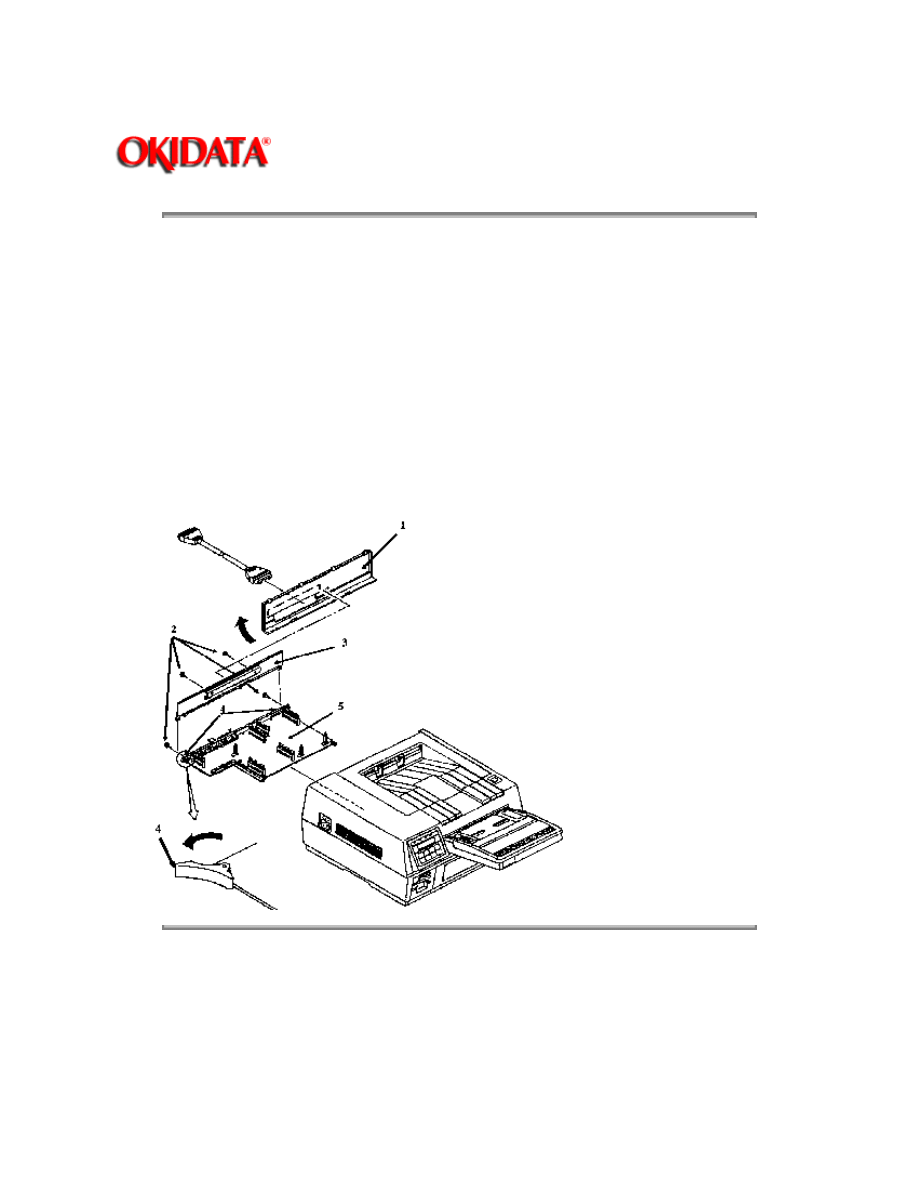
3.2.01 Main Controller Board (RPSS)
1. Power
OFF
the printer.
2. Remove the AC connector.
3. Remove the interface cable.
4. Pull the rear panel (1) backward and remove.
5. Loosen the four screws (2) on the inner panel (3).
6. Open the lock clips (4), and pull the main controller board (5) out.
7. Remove the inner panel.
Note:
The screws (2) are captive; they cannot be completely removed.
The Program ROM Board is not shown in this drawing.
Copyright 1997, Okidata, Division of OKI America, Inc. All rights reserved. See the OKIDATA Business
Partner Exchange (BPX) for any updates to this material. (http://bpx.okidata.com)
Page: 36
Service Guide OL840
Chapter 3 Maintenance & Disassembly
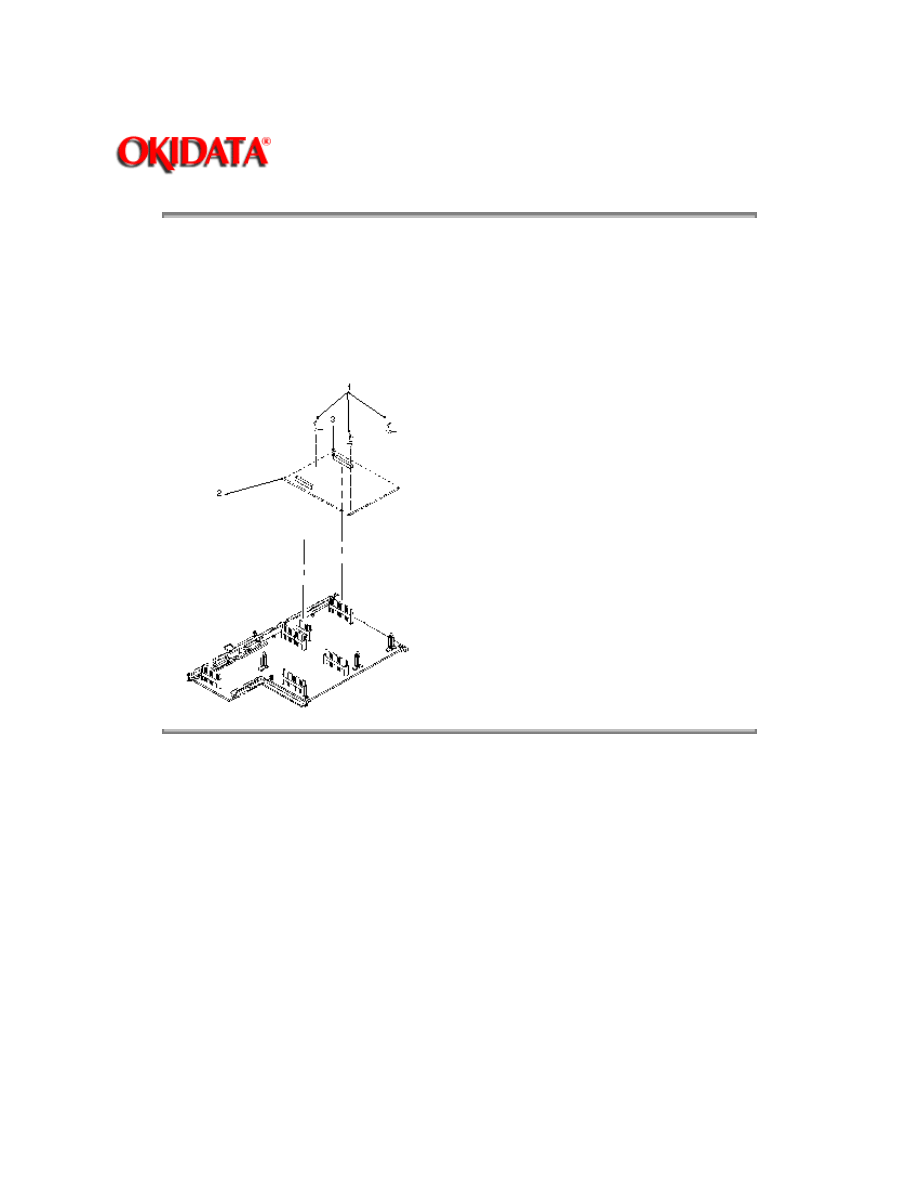
3.2.02 Program ROM Board (RPSR)
1. Remove the main controller board (RPSS). (See 3.2.01)
2. Using a needle nose pliers, detach the nylon latches (1).
3. Lift the program ROM board (2) from the main controller board being careful not to lose the
circuit board retainer clip (3).
Copyright 1997, Okidata, Division of OKI America, Inc. All rights reserved. See the OKIDATA Business
Partner Exchange (BPX) for any updates to this material. (http://bpx.okidata.com)
Page: 37
Service Guide OL840
Chapter 3 Maintenance & Disassembly
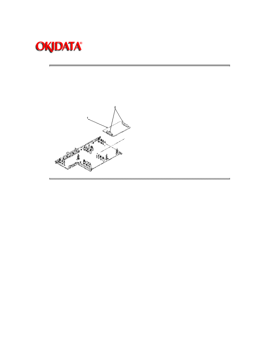
3.2.03 Optional Expansion RAM Board (REXM)
1. Remove the main controller board (RPSS). (See 3.2.01)
2. Pull up and remove the optional Expansion RAM PCB (1) from the connectors MEM (2).
Copyright 1997, Okidata, Division of OKI America, Inc. All rights reserved. See the OKIDATA Business
Partner Exchange (BPX) for any updates to this material. (http://bpx.okidata.com)

Page: 38
Service Guide OL840
Chapter 3 Maintenance & Disassembly
3.3 ADJUSTMENTS AND SERVICE CHECKS
3.3.01 General Information
The first four adjustments (Actual Page Count, Modified Page Count, Vertical Print Start Position
and LED Head Drive Time) are performed by changing addresses on the EEPROM located on the
Engine Controller Printer circuit board.
Please refer to Section Three of the OL800/820 Service Handbook for these procedures (
).
Copyright 1997, Okidata, Division of OKI America, Inc. All rights reserved. See the OKIDATA Business
Partner Exchange (BPX) for any updates to this material. (http://bpx.okidata.com)

Page: 39
Service Guide OL840
Chapter 3 Maintenance & Disassembly
3.4 CLEANING
3.4.01 General Information
Remove any dropped toner and dust. Clean inside and around the printer with a vacuum cleaner
(equipped with a toner filter) when necessary.
Refer to Section 3.4 of the OL800/820 Service Handbook for information on cleaning the printer (
).
Copyright 1997, Okidata, Division of OKI America, Inc. All rights reserved. See the OKIDATA Business
Partner Exchange (BPX) for any updates to this material. (http://bpx.okidata.com)

Page: 40
Service Guide OL840
Chapter 3 Maintenance & Disassembly
3.5 LUBRICATION
3.5.01 General Information
Refer to Section 3.5 of the OL830 Service Handbook for information on lubricating the printer (
).
Copyright 1997, Okidata, Division of OKI America, Inc. All rights reserved. See the OKIDATA Business
Partner Exchange (BPX) for any updates to this material. (http://bpx.okidata.com)

Page: 41
Service Guide OL840
Chapter 3 Maintenance & Disassembly
3.6 CONSUMABLES
The OL840 uses the same consumables as the OL800 and OL820.
3.6.01 Image Drum Counter Reset
When the image drum cartridge is replaced, the image drum counter must be reset.
1. Press and hold
RECOVER/RESET
while powering on the printer.
2. This resets the counter.
3.6.02 Ozone Filter
The ozone filter is replaced when the image drum cartridge is replaced.
1. Power off the printer.
2. Place a screwdriver in the slot under the lower portion of the fan cover and lift the
screwdriver slightly to remove the fan cover.
3. Replace the filter.
4. Replace the cover.
Copyright 1997, Okidata, Division of OKI America, Inc. All rights reserved. See the OKIDATA Business
Partner Exchange (BPX) for any updates to this material. (http://bpx.okidata.com)

Page: 42
Service Guide OL840
Chapter 4 Failure & Repair Analysis
4.1 OL840 TROUBLESHOOTING
4.1.01 General Information
Section Four of the OL800/820 Service Handbook should be used to troubleshoot the OL840.
Listed below are the differences between troubleshooting the OL800/820 printers and the OL840 printers.
· When told to replace the CTLZ Board, replace the RPSS Board.
Both boards are Main Controller Boards.
· When told to replace the Program Cartridge, replace the Program ROM Board.
There is no Program Cartridge in the OL840.
The printers firmware is located on the Program ROM Board.
This board is attached to the Main Controller Board.
· When told to replace the Memory Expansion Chip Set, replace the Memory Expansion
Board (REXM).
· When the Engine Control Board (LLAB-2), is replaced, remember that the OL840
EEPROM is
NOT
identical to the OL800/820 EEPROM.
Copyright 1997, Okidata, Division of OKI America, Inc. All rights reserved. See the OKIDATA Business
Partner Exchange (BPX) for any updates to this material. (http://bpx.okidata.com)

Page: 43
Service Guide OL840
Chapter 4 Failure & Repair Analysis
4.1.02 LCD Display Messages (PostScript Mode)
The following messages may be displayed when the printer is in the PostScript mode.
Refer to Section Four of the OL800/820 Service Handbook for LCD Messages displayed
in the Emulation Mode (
).
LCD MESSAGE
DEFINITION
CORRECTIVE ACTION
ON-LINE .PS IDLE
The printer is in the online mode.
Normal Indication
OFF-LINE .PS
The printer is in the off-line mode.
The printer receives data but does
not process any data.
Normal Indication
ON-LINE .PS
PROCESSING
The printer is processing the
received data
Normal Indication
ON-LINE .PS
WAITING
Waiting for receive data.
Normal Indication
ON-LINE .PS
PRINTING
The printer is printing received data.
Normal Indication
ON-LINE .PS
PRINTER BUSY
The ON-LINE key is pressed during
processing waiting or printing.
Recovers automatically.
Otherwise press the
RECOVER key to return to
IDLE.
ON-LINE .PS
FLUSHING JOB
After PRINTER BUSY appeared the
RECOVER key was pressed and all
data in the receive buffer was
invalidated.
Normal Indication
DOING START PAGE
The start page setting was ON when
the power was turned on. Printing
starts from the start page in about
one minute.
Normal Indication

ON-LINE .PS
CHANGE DRUM
The drum is aging .
Replace the drum Change
the software to the
emulation mode hold down
the recover key and turn on
the power. Check that
DRUM CTR RESET
appears on the LCD.
ON-LINE. PS FUSER
LIFE
End of thermal fuser life.
Replace the thermal fuser
and reset the fuser counter.
ON-LINE .PS TONER
LOW
The printer is low on toner.
Replace the toner
cartridge.
WARMING UP
The printer is warming up.
Normal Indication
ERROR CARD
There is an error in the data on the
font card (checksum error).
Try reinstalling the Font
Card. Replace the Font
Card.
INITIALIZING
Firmware is initializing
Normal Indication. Will be
displayed when switching
between software modes
(Postscript and Emulation).
Copyright 1997, Okidata, Division of OKI America, Inc. All rights reserved. See the OKIDATA Business
Partner Exchange (BPX) for any updates to this material. (http://bpx.okidata.com)

Page: 44
Service Guide OL840
Chapter A Reference Charts
A.1 OVERVIEW
A.1.01 General Information
This section describes the characteristics of the printed circuit boards used in the printer. The following
areas are covered.
· Firmware
· Fuses
· Jumpers
· Switches
· Sensors
· Test Points
Where an item is not applicable, the word
NONE
will be listed.
Copyright 1997, Okidata, Division of OKI America, Inc. All rights reserved. See the OKIDATA Business
Partner Exchange (BPX) for any updates to this material. (http://bpx.okidata.com)

Page: 45
Service Guide OL840
Chapter A Reference Charts
A.2 CHARTS
Index to Charts
Description Acronym Section
Main Control Board (without ROM)
RPSS
A.2.01
Program ROM Board
RPSR
A.2.02
RAM Board
REXM
A.2.03
Copyright 1997, Okidata, Division of OKI America, Inc. All rights reserved. See the OKIDATA Business
Partner Exchange (BPX) for any updates to this material. (http://bpx.okidata.com)
Page: 46
Service Guide OL840
Chapter A Reference Charts
A.2.01 Main Control Board (RPSS)
Firmware
NONE
Fuses
NONE
Jumpers
T1: +5vdc at Pin 18 of Centronics Parallel Interface
1-2: +5vdc not present
2-3: +5vdc present
T2: +5vdc at Pin 18 of RS232-C Serial Interface
1-2: +5vdc not present
2-3: +5vdc present
Sensors
NONE
Switches
NONE
Test Points
NONE
Copyright 1997, Okidata, Division of OKI America, Inc. All rights reserved. See the OKIDATA Business
Partner Exchange (BPX) for any updates to this material. (http://bpx.okidata.com)

Page: 47
Service Guide OL840
Chapter A Reference Charts
A.2.02 Program ROM Board (RPSR)
Firmware
O1A (4M bit) (Masked) Bit-mapped Fonts
O1B (4M bit) (Masked) Bit-mapped Fonts
02A through 09A (8 PROMS) - Postscript Interpreter
02B / 03B - Program for Emulation Mode
Fuses
NONE
Jumpers
NONE
Sensors
NONE
Switches
NONE
Test Points
NONE
Notes:
When using XON/XOFF Protocol, the OL840 will lockup when receiving serial data after the buffer
fills and it attempts to send the first DC3.
In order to correct this problem on field units, FCO 7761 should be installed. The emulation
PROMS (02B, 03B) on the program ROM board (RPSR) are replaced with Rev. 1.41.
Field Units Covered by the FCO
Serial Numbers 010A0015157 and below (120 volt)
Serial Numbers 010A0000144 and below (220 volt)
Kit Part Number: 58221301
Order this kit through Okidata Logistics.
Copyright 1997, Okidata, Division of OKI America, Inc. All rights reserved. See the OKIDATA Business
Partner Exchange (BPX) for any updates to this material. (http://bpx.okidata.com)
Page: 48
Service Guide OL840
Chapter A Reference Charts
A.2.03 RAM Board (REXM) (Option)
Firmware
NONE
Fuses
NONE
Jumpers
NONE
Sensors
NONE
Switches
NONE
Testpoints
NONE
Copyright 1997, Okidata, Division of OKI America, Inc. All rights reserved. See the OKIDATA Business
Partner Exchange (BPX) for any updates to this material. (http://bpx.okidata.com)
Page: 49
Service Guide OL840
Chapter B Illustrated Parts Listing
B.1 COMPATIBILITY CHARTS
Parts which are unique to the OL800 and OL820, +, +
Item
Description
Okidata Part Number
61
PCB: CTLZ (Main Controller)
55046101
62
PCB: PRGZ (w/o ROM)
55046501
Parts which are unique to the OL820, +, +
Item
Description
Okidata Part Number
63
PCB: OkiXpress
Scalable Font Card
(w/ROM)
21025001
Options which are interchangeable between the OL800 and OL820, +, +
Item
Description
Okidata Part Number
64
PCB: MEMZ
55046601
65
PCB: CMIZ
(Multi-port)
55050001
66
PCB: RMIZ
(Multi-port)
55050101
Parts Unique to the OL840
Item
Description
Okidata Part Number
67
PCB: RPSS (Main Controller
Board)
55051001

68
EEPROM: For use on Engine
Control Board
55921901
69
PCB: RPSR (PROM Board) w/o
ROM
55051101
Options Unique to the OL840
Item
Description
Okidata Part Number
70
PCB: REXM (2MB RAM) Option
55051601
Copyright 1997, Okidata, Division of OKI America, Inc. All rights reserved. See the OKIDATA Business
Partner Exchange (BPX) for any updates to this material. (http://bpx.okidata.com)

Page: 50
Service Guide OL840
Chapter B Illustrated Parts Listing
Interchangeable Parts (OL800, OL820 and OL840)
Parts which are interchangeable between the OL800,, OL820 and OL840, +, +
Item
Description
Okidata Part Number
1
Assembly: Exit Roller
50066501
2
Assembly: Face-Up Stacker
50066601
3
Cover: Upper (Program Cartridge)
50070201
4
Cover: Lower (Program Cartridge)
50070301
5
Assembly: Resist Roller
50079101
6
Assembly: Back-Up Roller
50079201
7
Assembly: Transfer Charger
50081601
8
Roller: Hopping (Assembly)
50081701
9
Panel: Operation (Assembly)
50213502
10
Unit: Lower
50213602
11
Cover: Upper (Assembly)
50213902
12
Panel: Inner
50214402
13
Unit: Paper Delivery
50214502
14
Spring: Bias (LED Head)
50914101
15
Spring: Clamp (LED)
50914301
16
Spring: Fusing Unit
50914601

17
Spring: Backup Roller
50914801
18
Spring: Cassette
50917001
19
Spring: Separator
50917101
20
Spring: Image Drum Tray
50917205
21
Gear: Idle "A"
51218401
22
Gear: Idle "B"
51218501
23
Gear: Idle (Base)
51218601
24
Gear: Speed Reduction
51218701
25
Base: Lower
53059401
26
Panel: Front (R)
53059501
27
Panel: Blind
53059601
28
Panel: Front (L)-B
53059701
29
Panel: Rear
53059801
30
Post
53329501
31
Separator
53500501
32
Fuser Pad
53500901
33
Contact: Ground
53505201
34
Foot: Rubber
53505301
35
Cable
53505430
36
Cable
53505431
37
Panel: Inner
53534201

38
PCB: LLAB-2 (Engine Controller) w/o ROM
55044402
39
PCB: LLCC (Engine Connection)
55044601
40
Unit: Fusing (120V)
55044901
41
PCB: LLID
55046001
42
PCB: CMBZ
55046201
43
PCB: LLIC
55046301
44
PCB: LNKZ
55046401
45
PCB: LLBB High Voltage
55047301
46
Microswitch Assembly - Cover Open
55050701
47
Filter: Ozone
55503501
48
Unit: LED Head
55619501
49
IC: EEPROM (LLAB) 84
55921901
50
Power Supply (120V)
56407702
51
Motor: Pulse (Resist)
56507401
52
Motor: Pulse (Main)
56507701
53
Assembly: DC Fan
56508501
54
Cord: AC
56609701
55
Connector: AKJ-40A
56725201
56
Unit: Upper (240V)
50213702
57
Roller: Hopping (2nd Tray)
53534301
58
Unit: Fusing (240V)
55044902

59
PCB: LLFC (2nd Tray)
55051401
60
Power Supply (240V)
56408102
Copyright 1997, Okidata, Division of OKI America, Inc. All rights reserved. See the OKIDATA Business
Partner Exchange (BPX) for any updates to this material. (http://bpx.okidata.com)
Wyszukiwarka
Podobne podstrony:
OKI OL 400 800 820 830 840 service manual
Okidata Jet 2020 Service Manual
hplj 5p 6p service manual vhnlwmi5rxab6ao6bivsrdhllvztpnnomgxi2ma vhnlwmi5rxab6ao6bivsrdhllvztpnnomg
Okidata Okipage 14e Parts Manual
Oberheim Prommer Service Manual
Korg SQ 10 Service Manual
MAC1500 service manual
Kyocera Universal Feeder UF 1 Service Manual
Proview RA783 LCD Service Manual
indesit witp82euy Service Manual
Glow Worm installation and service manual Hideaway 70CF UIS
Proview PZ456 LCD Service Manual
Glow Worm installation and service manual Ultimate 50CF UIS
ewm2000 service manual
Glow Worm installation and service manual Ultimate 60CF UIS
Proview SH770I LCD Service Manual
więcej podobnych podstron