Page: 1
Service Guide OL400
Chapter 0 About This Manual
OL400 / 800 / 820 / 830 / 840
LED Page Printers
Adobe Acrobat printable reference
copy of the OKIDATA Service Training Manual.
09/17/97
Note: This Adobe Acrobat version of the Okidata Service Training Manual was built with the
pictures rendered at 300 dpi, which is ideal for printing, but does not view on most
displays well.
Copyright 1997, Okidata, Division of OKI America, Inc. All rights reserved. See the OKIDATA Business
Partner Exchange (BPX) for any updates to this material. (http://bpx.okidata.com)

Table of Contents
Page
Service Guide OL400
0 About This Manual
Front Cover
1
Copyright & Manual Revision
2
Part Number
3
1 Product Specifications
1.1 Overview
4
1.2 Physical Specifications
5
1.3 Print Specifications
6
1.4 Paper Specifications
7
1.5 Power Requirements
8
1.8 Options
9
1.9 Consumables
10
1.10 Reliability Data
11
2 Principles of Operation
2.1 Printer Overview
12
2.2 Main Control Function
13
....2.2.02 Centronics Parallel Interface
14
....2.2.03 RS-232C Serial Interface
15
....2.2.04 Optional Font Card
16
....2.2.05 Optional RAM Board / IC Set
17
2.3 Printer Control Function
18
....2.3.02 Operation Panel
19
....2.3.03 Engine Board
20
....2.3.04 Power Supply Unit
21
....2.3.05 Fuser Unit
22
....2.3.06 Main Motor (Drum Motor)
23
....2.3.07 LED Head
24
....2.3.08 Resist Motor
25
....2.3.09 DC Fan
26
2.4 Mechanical Operation Description
27
....2.4.02 OL400 Printing Process
28
....2.4.03 Process Descriptions
29
2.5 Sensors And Switches
30
....2.5.01 Sensors and Switches
31
....2.5.02 Sensor Functions
32
3 Maintenance & Disassembly
3.1 Maintenance
33
....3.1.02 Maintenance Tools
34
....3.1.03 Maintenance Precautions
35
3.2 Disassembly/Assembly Procedures
36
....3.2.01 Upper Cover
37
....3.2.02 LED Head
38

Table of Contents
Page
....3.2.03 Interface Board
39
....3.2.04 RAM Board (Option)
40
....3.2.05 Main Controller Board
41
....3.2.06 Engine Controller Circuit Board (LLAB)
42
....3.2.07 Main Motor
43
....3.2.08 DC Fan Assembly
44
....3.2.09 Idle Gears "A" and "B", and the Reduction Gear
45
....3.2.10 Power Supply Unit
46
....3.2.11 Upper Unit
47
....3.2.12 Fusing Unit
48
....3.2.13 Backup Roller
49
....3.2.14 Transfer Charger Assembly
50
....3.2.15 Resist Roller Assembly
51
....3.2.16 Idle Gear C
52
....3.2.17 Paper Supply Unit
53
....3.2.18 Resist Motor
54
....3.2.19 Engine Connection Board
55
....3.2.20 Hopping Roller
56
....3.2.21 Separator
57
....3.2.22 Ozone Filter
58
3.3 Adjustments And Service Checks
59
....3.3.02 Actual Page Count
60
....3.3.03 Modified Page Count
61
....3.3.04 Vertical Print Start Position Adjustment
62
....3.3.05 Setting the LED Head Drive Time
63
....3.3.06 Voltage Adjustment (+5 vdc)
64
....3.3.07 Darkness Control
65
3.4 Cleaning
66
4 Failure & Repair Analysis
4.1 Overview
67
4.2 Troubleshooting Updates
68
4.3 Reporting Problems
69
4.4 Troubleshooting Tips
70
4.5 Fault Alarms
71
....4.5.02 Error Messages Table
72
....4.5.03 Output SamplesTitle of Section
73
4.6 Repair Analysis Procedures
74
....4.6.02 RAP Index
75
........RAP 01 Printer Does Not Initialize
76
........RAP 02: Paper Feed Jam Alarm
77
........RAP 03: Paper Jam Alarm
78
........RAP 04: Size Tray Error Alarm
79
........RAP 05: Engine Error - Fusing Problem Alarm
80
........RAP 06: Engine Error Alarm
81

Table of Contents
Page
........RAP 07: Light or Blurred Images
82
........RAP 09: Blank Output
83
........RAP 10: Vertical Black Stripes
84
........RAP 11: Repeating Marks
85
........RAP 12: Blank Spots
86
........RAP 13: Vertical White Stripes
87
........RAP 14: Black Page
88
........RAP 15: Poor Fusing
89
4.7 Self-Tests
90
A Reference Charts
A.1 Overview
91
A.2 Charts
92
....A.2.01 Main Controller Board (LBPE / LBPF)
93
....A.2.02 Engine Controller Board (LLAB)
94
....A.2.03 Operator Panel PCB (LLDC)
95
....A.2.04 Engine Connection PCB (LLCC)
96
....A.2.05 Centronics Parallel Interface PCB (LLCP / LLCQ)
97
....A.2.06 RS-232C Interface PCB (LLRS)
98
....A.2.07 Expansion RAM Board (optional) (RAMK / RAMH)
99
....A.2.08 Power Interconnect Board (LLIE)
100
....A.2.09 Power Supply Unit
101
B Illustrated Parts Listing
B.1 Illustrated Parts Listing
102
....B.1.02 Definitions of Terms
103
....B.1.03 Parts Ordering Information
104
B.2 Charts
105
....B.2.01 Items 1 - 7
106
....B.2.02 Items 8 - 16
107
....B.2.03 Items 17 - 27, and 41
108
....B.2.04 Items 28 - 35
109
....B.2.05 Items 36 - 40
110

Page: 2
Service Guide OL400
Chapter 0 About This Manual
This document may not be reproduced without written permission of the Okidata® Technical
Training Group. Every effort has been made to ensure the accuracy of the information contained
in this training course. Okidata is not responsible for errors beyond its control.
© 1994 by Okidata All rights reserved.
First Edition, March 1992
Second Edition May, 1994
Written and produced by the Okidata Technical Training Group
Please address any comments on this publication to:
Technical Training Group
Okidata
532 Fellowship Road
Mount Laurel, NJ 08054-3499
Fax Number: (609) 235-2600, ext. 7034
Okilink Login Name: Technical Training
Okidata is a registered trademark of Oki Electric Industry Company, Ltd.; marques deposee de
Oki Electric Industry Company, Ltd.; marca registrada, Oki Electric Industry Company, Ltd.
Microline is a registered trademark of Oki Electric Industry Company, Ltd.
Centronics is a registered trademark of Centronics Inc.
Diablo is a registered trademark of Xerox Corporation
Epson is a registered trademark of Seiko Epson Corporation
IBM is a registered trademark of International Business Machines, Inc.
LaserJet and LaserJet+ are registered trademarks of Hewlett Packard Corporation
Proprinter is a registered trademark of International Business Machines, Inc.
Note: The OL400 Service Training course is part of the OL-Series Training Course and can
not be purchased separately.
Copyright 1997, Okidata, Division of OKI America, Inc. All rights reserved. See the OKIDATA Business
Partner Exchange (BPX) for any updates to this material. (http://bpx.okidata.com)

Page: 3
Service Guide OL400
Chapter 0 About This Manual
Note: The OL400 Service Training course is part of the OL-Series Training Course and can not be
purchased separately.
THE OL400/800/820/830/840 VIDEO TRAINING KIT covers the following
products:
OL400
OL800
OL820
OL830
OL840
The following items are included in the kit:
OL400 Service Handbook
OL800/820 Service Handbook
OL830 Service Handbook
OL840 Service Handbook
Service Training Video
OL400/800/820 User's Documentation
OL830 User's Documentation
OL840 User's Documentation
Price: $95.00 ($124.00 Canadian)
P/N 58226902
Copyright 1997, Okidata, Division of OKI America, Inc. All rights reserved. See the OKIDATA Business
Partner Exchange (BPX) for any updates to this material. (http://bpx.okidata.com)

Page: 4
Service Guide OL400
Chapter 1 Product Specifications
1.1
OVERVIEW
1.1.01 General Information
The OL400 is a desktop, page printer, using a stationary LED head and dry electrophotography as
its exposure and development method. The printer has a resolution of 300 x 300 dots per inch and
a continuous print speed of 4 letter-sized sheets per minute.
A 512K page memory is standard on the OL400; this can be expanded to 1.5 or 2.5 megabyte
with an optional RAM printed circuit board and a memory expansion chip set. Twenty-five resident
fonts are included in the OL400 and five optional font cards are currently available. Downloadable
fonts can also be used with this printer.
The printer can be purchased with either a Centronics parallel interface or an RS-232C serial
interface.
The OL400's consumables consist of the toner kit, which include a toner cartridge, lens cleaner,
and a fuser cleaner pad and the image drum kit which includes the drum cartridge and ozone
filter.
A letter-size paper tray is included with the printer, and legal, and envelope trays are also
available. Paper feeding can be done automatically or manually.
The printer will print on a variety of paper types, labels, envelopes, and transparencies.
Copyright 1997, Okidata, Division of OKI America, Inc. All rights reserved. See the OKIDATA Business
Partner Exchange (BPX) for any updates to this material. (http://bpx.okidata.com)

Page: 5
Service Guide OL400
Chapter 1 Product Specifications
1.2
PHYSICAL SPECIFICATIONS
1.2.01 Outside Dimensions
Width: 17.72"
Height:5.24"
Length: 17.72"
1.2.02 Printer Weight
24 lbs.
1.2.03 LED Array
Number of LED Elements - 2560
Copyright 1997, Okidata, Division of OKI America, Inc. All rights reserved. See the OKIDATA Business
Partner Exchange (BPX) for any updates to this material. (http://bpx.okidata.com)

Page: 6
Service Guide OL400
Chapter 1 Product Specifications
1.3
PRINT SPECIFICATIONS
1.3.01 Print Specifications
Development method: Dry electrophotography
Exposure method: LED stationary head
1.3.02 Print Speed
First print: 28 seconds maximum (letter size)
Continuous print: 4 sheets/minute. (letter size)
Warm-up time: 40 seconds maximum [at room temperature 77oF (25oC) and rated voltage (120
VAC)]
1.3.03 Symbol Sets
Thirty-nine symbol sets are available with the OL400.
1.3.04 Available Fonts
There are twenty-five resident fonts in the OL400.
1.3.05 Paper Feed Method
Automatic feed
Manual Feed
1.3.06 Paper Delivery Method
Face down/face up
1.3.07 Resolution
300 x 300 dots/inch
Copyright 1997, Okidata, Division of OKI America, Inc. All rights reserved. See the OKIDATA Business
Partner Exchange (BPX) for any updates to this material. (http://bpx.okidata.com)

Page: 7
Service Guide OL400
Chapter 1 Product Specifications
1.4
PAPER SPECIFICATIONS
1.4.01 Paper Types
Letter
Size: 8.5" x 11"
Feed: Automatic or Manual
Weight:Minimum 16 lbs
Maximum 24 lbs
Recommended 20 lbs
Legal
Size: 8.5" x 14"
Feed: Automatic (with optional paper tray) or Manual
Weight:Minimum 16 lbs
Maximum 24 lbs
Recommended 20 lbs
Envelope
Size:Minimum 3.5" x 7.5"
Maximum 7.2" x 10.1"
Feed: Automatic (with optional paper tray) or Manual
Weight:Minimum 16 lbs
Maximum 24 lbs
Recommended 20 lbs
Labels
Manual feed / Face up delivery only
Use labels designed specifically for laser/page printers.
Transparencies
Manual feed / Face up delivery only
Must be able to withstand the heat of the fusing process.
Copyright 1997, Okidata, Division of OKI America, Inc. All rights reserved. See the OKIDATA Business
Partner Exchange (BPX) for any updates to this material. (http://bpx.okidata.com)

Page: 8
Service Guide OL400
Chapter 1 Product Specifications
1.5
POWER REQUIREMENTS
1.5.01 Input Power
120 VAC +5.5%, -15%
220/240 VAC +/-10%
1.5.02 Power Consumption
Approximately 800 W maximum during operation
1.6
ENVIRONMENTAL CONDITIONS
1.6.01 Ambient Temperature and Relative Humidity
While operating:
50° to 89° F
10° to 32° C
20 to 80% Relative Humidity
While in storage:
14° to 122° F
10° to 50° C
1.6.02 Printer Noise Level
During operation: 50 dB maximum
At standby: 43 dB maximum
1.7
AGENCY APPROVALS
FCC Class B
UL 478 Ver.5
CSA 22.2 220
Copyright 1997, Okidata, Division of OKI America, Inc. All rights reserved. See the OKIDATA Business
Partner Exchange (BPX) for any updates to this material. (http://bpx.okidata.com)
Page: 9
Service Guide OL400
Chapter 1 Product Specifications
1.8
OPTIONS
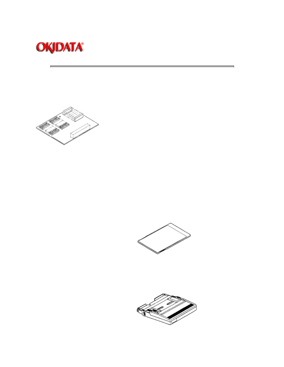
1.8.01 RAM Expansion Board
1 megabyte (expands printer memory to 1.5 megabyte)
Technician installed
1.8.02 RAM Expansion Chip Set
Technician installed
1 megabyte memory expansion chip set used in conjunction with the RAM Expansion Board
option. (expands printer memory to 2.5 megabyte)
1.8.03 Font ROM Cards
Tax
Courier
Roman
Prestige Elite
Letter Gothic
1.8.04 Paper Trays
Letter size
Legal size
Envelope

1.8.05 Interface Boards
RS-232C Serial Interface Board
Centronics Parallel Interface Board
Technician installed
Copyright 1997, Okidata, Division of OKI America, Inc. All rights reserved. See the OKIDATA Business
Partner Exchange (BPX) for any updates to this material. (http://bpx.okidata.com)

Page: 10
Service Guide OL400
Chapter 1 Product Specifications
1.9
CONSUMABLES
Toner Cartridge Kit (P/N 52104201)
One Toner Cartridge
One Fuser Cleaner Pad
One LED Head Cleaning Kit
Image Drum Cartridge (P/N 56106601)
One Image Drum Cartridge
One Ozone Filter
Copyright 1997, Okidata, Division of OKI America, Inc. All rights reserved. See the OKIDATA Business
Partner Exchange (BPX) for any updates to this material. (http://bpx.okidata.com)

Page: 11
Service Guide OL400
Chapter 1 Product Specifications
1.10
RELIABILITY DATA
1.10.01 Printer Mean Time Between Failure (MTBF)
Approximately 18,000 pages
1.10.02 Printer Mean Time To Repair (MTTR)
Approximately 20 minutes
1.10.03 Estimated Printer Life
Approximately 180,000 pages (5 years)
1.10.04 Printer Duty Cycle
Approximately 3,000 pages @ 5% print density
Copyright 1997, Okidata, Division of OKI America, Inc. All rights reserved. See the OKIDATA Business
Partner Exchange (BPX) for any updates to this material. (http://bpx.okidata.com)
Page: 12
Service Guide OL400
Chapter 2 Principles of Operation
2.1
PRINTER OVERVIEW
2.1.01 General Information
This section describes the operation of the printer in the order listed below.
Main Control Function {
}
Printer Control Function {
}
Mechanical Operation
{
}
Sensors and Switches
{
}
Copyright 1997, Okidata, Division of OKI America, Inc. All rights reserved. See the OKIDATA Business
Partner Exchange (BPX) for any updates to this material. (http://bpx.okidata.com)

Page: 13
Service Guide OL400
Chapter 2 Principles of Operation
2.2
MAIN CONTROL FUNCTION
2.2.01 General Information
The main control function controls the reception of data from the host interface, processes
command signals, processes the image signals, controls the printer unit, outputs data, and
controls the operation panel.
The main control function consists of the items listed below.
CPU 80186-8
Font ROM (512 kbytes)
Page buffer (512 kbytes)
DRAM controller chip (MSM73V007)
Print controller chip (MSM75HJ014)
Font controller chip (MSM60791)
Programmable I/O (82C55A-2GS)
Interface Control
Centronics Parallel Interface Board
RS-232C Serial Interface Board
Optional Font Card
Optional RAM
Copyright 1997, Okidata, Division of OKI America, Inc. All rights reserved. See the OKIDATA Business
Partner Exchange (BPX) for any updates to this material. (http://bpx.okidata.com)

Page: 14
Service Guide OL400
Chapter 2 Principles of Operation
2.2.02 Centronics Parallel Interface
The following operations are carried out during
SELECT
mode once the STB-N signal is received
from the host interface.
The BUSY-P signal is sent to the host interface.
Simultaneously with fetching data to the Q4 IC at the last transition of the STB signal, the
RXIPT-P signal is sent to the CPU to inform it of receipt of data.
The CPU reads data received from the Q4 IC by the RD-N signal, and turns off the BUSY signal
to the host interface.
Upon turning off the BUSY signal, the ACK-N signal is sent to the host interface to acknowledge
reception processing.
Copyright 1997, Okidata, Division of OKI America, Inc. All rights reserved. See the OKIDATA Business
Partner Exchange (BPX) for any updates to this material. (http://bpx.okidata.com)

Page: 15
Service Guide OL400
Chapter 2 Principles of Operation
2.2.03 RS-232C Serial Interface
The 8251 Universal Synchronous/Asynchronous Receiver Transmitter is used as a controller.
This serial I/F converts serial data received from the host I/F into parallel data for use by the CPU.
It also converts parallel data from the CPU into serial data to be sent to the Host I/F.
READY/BUSY or X-ON/X-OFF are used as the communication protocol between the Host I/F and
OL400. These can be selected through the Menu.
The baud rate, character length, parity check, stop bit, etc., are automatically written into the
82C51 from the menu, so hardware switches are not required.
Copyright 1997, Okidata, Division of OKI America, Inc. All rights reserved. See the OKIDATA Business
Partner Exchange (BPX) for any updates to this material. (http://bpx.okidata.com)

Page: 16
Service Guide OL400
Chapter 2 Principles of Operation
2.2.04 Optional Font Card
In addition to the twenty-five resident fonts, an optional font IC card is available.
The CD-N signal detects the option font card.
Copyright 1997, Okidata, Division of OKI America, Inc. All rights reserved. See the OKIDATA Business
Partner Exchange (BPX) for any updates to this material. (http://bpx.okidata.com)

Page: 17
Service Guide OL400
Chapter 2 Principles of Operation
2.2.05 Optional RAM Board / IC Set
The expansion RAM board contains 1 Mbyte of memory and sockets for an additional 1 Mbyte.
This RAM is in addition to the 512 Kbyte on the Main Control Board.
Copyright 1997, Okidata, Division of OKI America, Inc. All rights reserved. See the OKIDATA Business
Partner Exchange (BPX) for any updates to this material. (http://bpx.okidata.com)

Page: 18
Service Guide OL400
Chapter 2 Principles of Operation
2.3
PRINTER CONTROL FUNCTION
2.3.01 General Information
The principle hardware components of the printer unit consist of the items listed below.
Operation Panel
Engine Board
Power Supply Unit
Fuser Unit
Main Motor
LED Head
Resist Motor
DC Fan
Copyright 1997, Okidata, Division of OKI America, Inc. All rights reserved. See the OKIDATA Business
Partner Exchange (BPX) for any updates to this material. (http://bpx.okidata.com)

Page: 19
Service Guide OL400
Chapter 2 Principles of Operation
2.3.02 Operation Panel
The following components make up the operation panel.
4-bit MPU (LC6543C)
LCD control driver (MSM6222B or HD44780)
LCD display (16 characters per line)
Operation panel sheet
LEDs (for online mode indication)
Operation buttons
The LCD control driver (MSM622B or HD44780) converts 4-bit character codes received from the
MPU into 8-bit character codes and retrieves the character pattern data (font) associated with the
8-bit character codes from the internal character generator for display on the LCD.
Operation Panel Interface
The operation panel is controlled by the operation panel interface located on the Main Control
Board via the Engine Board.
Copyright 1997, Okidata, Division of OKI America, Inc. All rights reserved. See the OKIDATA Business
Partner Exchange (BPX) for any updates to this material. (http://bpx.okidata.com)

Page: 20
Service Guide OL400
Chapter 2 Principles of Operation
2.3.03 Engine Board
The Engine Board is composed of the items listed below.
MPU80C51, or MPU83C154 (8-bit CPU)
LLAB Revision 11
The MPU 83C154 contains the printer control program in its internal ROM.
Therefore, the external ROM (Q1) is not required on Revision 11.
MSM73H019GS (80 pin LSI)
EPROM (Printer Control Program)
EPROM
This 1-Kbit electrically erasable PROM (EEPROM) is loaded with the following data:
Total number of sheets printed after installation
Total number of sheets printed with the current drum
Total number of sheets printed with the current fuser
Setting of time required from the completion of printing to Stand-by
Feed length needed to feed the paper to a printable position.
Print starting line on paper (Top margin)
LED head drive time.
NOTE:
The EEPROM preserves the above data while the supply voltage is off.
The count of the total number of sheets printed after installation cannot be reset.
The count of the total number of sheets printed with the drum currently in use should be
taken as a rough measure of the useful life of the drum.
It is reset to zero when the drum is replaced by holding down the
RESET
button and
applying power to the printer.
Copyright 1997, Okidata, Division of OKI America, Inc. All rights reserved. See the OKIDATA Business
Partner Exchange (BPX) for any updates to this material. (http://bpx.okidata.com)

Page: 21
Service Guide OL400
Chapter 2 Principles of Operation
2.3.04 Power Supply Unit
The power supply unit generates the following voltages from the AC input voltage.
Voltage
Purpose
+5vdc
Logic Levels, LED Head Drive Voltage
+12vdc
Interface Line Voltage
-12vdc
Interface Line Voltage
+38vdc
Motor/Fan Drive Voltage: High Voltage Source
+5Kvdc
Transfer Charge Voltage
-6Kvdc
Drum Charge Voltage
-600vdc
Charge Grid Voltage
-550, -400vdc
Developer Bias Voltages
High Voltage Drive
The high voltage circuit provides a charge voltage (about -6Kvdc), a transfer voltage (about +5
Kvdc), a grid voltage (about -600 vdc), and a developer bias voltages (about -550vdc and
-400vdc). Of these voltages, the first two are generated from a high voltage power supply. The
grid connects to the ground via a varistor on the medium-voltage generation circuit (LLAB-PCB). It
is kept at about -680 vdc during charging.
Copyright 1997, Okidata, Division of OKI America, Inc. All rights reserved. See the OKIDATA Business
Partner Exchange (BPX) for any updates to this material. (http://bpx.okidata.com)

Page: 22
Service Guide OL400
Chapter 2 Principles of Operation
2.3.05 Fuser Unit
The fuser unit heater is controlled by a thermistor, a comparator, an LSI, and a CPU to keep the
heat roller surface temperature within a predetermined range (about 150 degrees). A thermostat
within the fuser unit prevents abnormal temperature rises in the fuser unit if the thermistor fails.
NOTE:
The CPU checks for a blown or shorted wire in the thermistor at power-on , setting a fuser alarm if
an error is detected.
The CPU also sets a fuser alarm if the proper temperature is not attained within a specified period
of time after power-on.
Upon detecting a fuser alarm, the CPU will halt (after printing the current page).
Copyright 1997, Okidata, Division of OKI America, Inc. All rights reserved. See the OKIDATA Business
Partner Exchange (BPX) for any updates to this material. (http://bpx.okidata.com)

Page: 23
Service Guide OL400
Chapter 2 Principles of Operation
2.3.06 Main Motor (Drum Motor)
The main motor is driven by the motor drive IC (M54646). It is a two-phase motor, driven by the
DM-PH1 and DM-PH2 signals.
Copyright 1997, Okidata, Division of OKI America, Inc. All rights reserved. See the OKIDATA Business
Partner Exchange (BPX) for any updates to this material. (http://bpx.okidata.com)

Page: 24
Service Guide OL400
Chapter 2 Principles of Operation
2.3.07 LED Head
Data on the 2,560 LEDs in the LED head is set in the shift register by the HD CLK signal. The
data is loaded in the latch circuit by the HD LD signal.
The on/off states of the LEDs are controlled by the signals STB1- STB4; 640 bits are turned on or
off at a time.
Copyright 1997, Okidata, Division of OKI America, Inc. All rights reserved. See the OKIDATA Business
Partner Exchange (BPX) for any updates to this material. (http://bpx.okidata.com)

Page: 25
Service Guide OL400
Chapter 2 Principles of Operation
2.3.08 Resist Motor
The resist motor is driven clockwise (Hopping), then counterclockwise (Paper Feed) by the motor
drive IC (LB1731). It is four-phase motor, driven according to the RM-H1, RM-H2, and RM ON-P
signals.
Copyright 1997, Okidata, Division of OKI America, Inc. All rights reserved. See the OKIDATA Business
Partner Exchange (BPX) for any updates to this material. (http://bpx.okidata.com)

Page: 26
Service Guide OL400
Chapter 2 Principles of Operation
2.3.09 DC Fan
The fan is controlled by the FAN ON-P signal from the LSI (MSM73H019). In order for the fan to
operate, the signal FAN SENSE-N must be active.
NOTE:
The fuser and the fan are not driven when the cover is open (reset).
If the fan fails to run, the fuser will turn off and an alarm is set. This prevents the next printout. If
the signal Fan Sense-N becomes inactive while printing, both the heater and the fan come to a
halt after the end of printout of the current page.
A fan alarm is generated when the fan is not sensed at power-on time.
The fan is driven for 1 minute after the fuser has been turned off. The fan speed is reduced if the
next PRINT signal is not received within 1 minute.
Copyright 1997, Okidata, Division of OKI America, Inc. All rights reserved. See the OKIDATA Business
Partner Exchange (BPX) for any updates to this material. (http://bpx.okidata.com)

Page: 27
Service Guide OL400
Chapter 2 Principles of Operation
2.4
MECHANICAL OPERATION DESCRIPTION
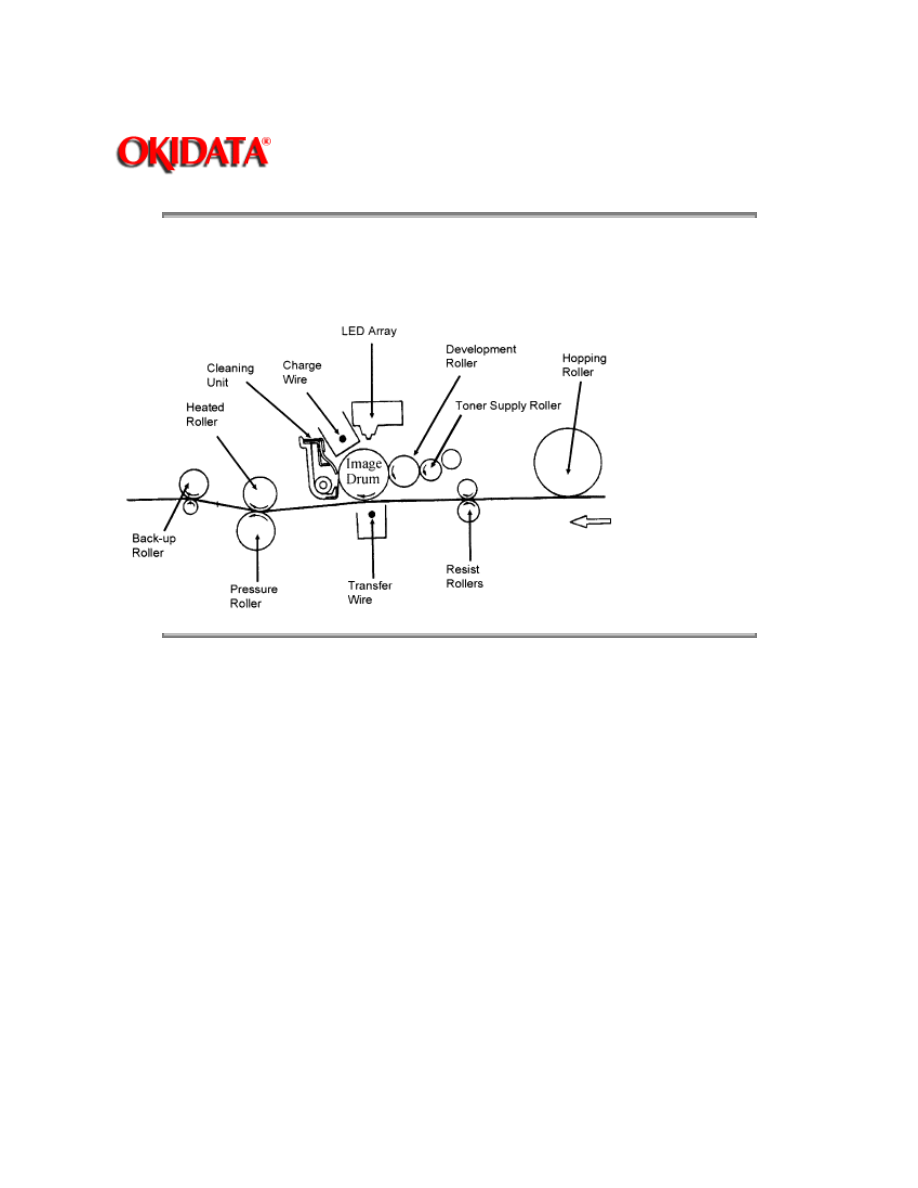
2.4.01 Basic Principles of Electrophotography
The printer turns on the LED head according to the data received from the controller. A charged
photoconductive material is exposed to light, forming a latent image on the material. This latent
image is developed by toner, with the resultant toner image being transferred to paper and fused
for printing.
The electrophotographic technology used in this printer is similar to that embodied in general
copying machines. The technology comprises the following processes:
Charging
The surface of the photoconductive material is uniformly charged.
Exposure
The charged photoconductive material is exposed to light, forming a latent image associated with
the print image on the photoconductive material.
Developing
Charged toner is attracted to the latent image by static electricity, making the image visible.
Transfer
The toner is attracted to the paper by a static charge.
Cleaning
Toner that remains on the photoconductive material is returned to the developer.
Fusing
The toner is fused to the paper using heat and pressure.
Copyright 1997, Okidata, Division of OKI America, Inc. All rights reserved. See the OKIDATA Business
Partner Exchange (BPX) for any updates to this material. (http://bpx.okidata.com)
Page: 28
Service Guide OL400
Chapter 2 Principles of Operation
2.4.02 OL400 Printing Process
The layout of the electrostatic printing process hardware is shown below.
Copyright 1997, Okidata, Division of OKI America, Inc. All rights reserved. See the OKIDATA Business
Partner Exchange (BPX) for any updates to this material. (http://bpx.okidata.com)
Page: 29
Service Guide OL400
Chapter 2 Principles of Operation
2.4.03 Process Descriptions
Hopping and Feeding
Hopping and feeding are accomplished by the resist motor, hopping roller, and resist rollers.
Turning the resist motor in the clockwise direction drives the hopping roller. Turning the resist
motor in the counter-clockwise direction drives the feed rollers.
Hopping
Hopping is loading paper from the tray.
The resist motor turns the hopping roller to advance the paper until the inlet sensor turns on.
After the paper has turned on the inlet sensor, the hopping roller advances the paper until it
contacts the feed roller (a predetermined length).
Feeding
Feeding is transporting the paper through the printer
After the end of hopping, the resist motor reverses and the resist rollers transport the paper
through the printer.
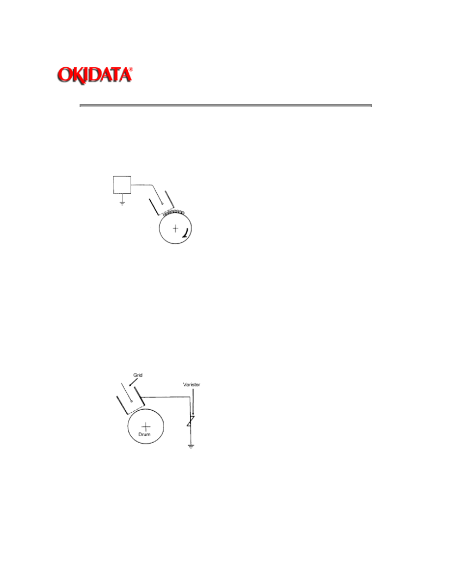
Charging
-6 Kvdc is applied to the charge wire. This causes negative ions to be generated in the vicinity of
the charge wire (corona discharge). The negative ions are discharged to the grid plate and the
image drum surface. Since the drum surface is not conductive (in the dark), the negative charge
(approximately -700 vdc) remains on the drum. To ensure that the drum surface is not charged
with more than -700 vdc, a varistor is connected between the grid and ground. If the grid voltage
exceeds -700 vdc, the varistor shunts this excess voltage to ground.
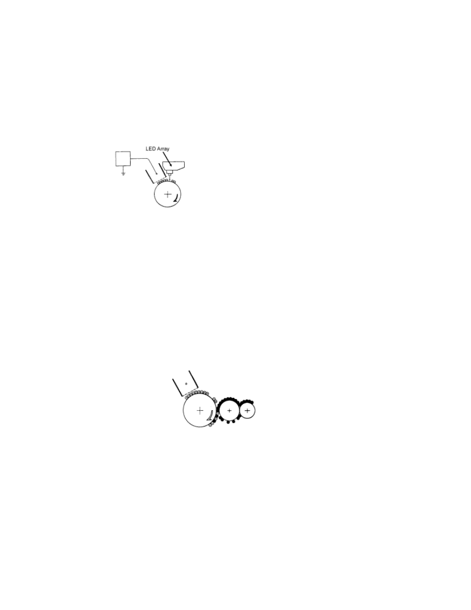
Exposure
Light emitted from the LED head is radiated to the image drum surface which is charged with
negative ions. The areas of the drum that light is directed to become conductive. This allows the
surface potential in these areas to drop from -700 vdc to approximately -100 vdc, thereby forming
a latent image associated with the image signals.
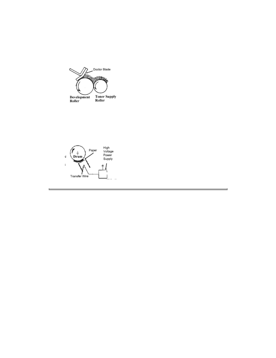
Developing
The toner supply roller and the development roller are supplied with bias voltages required during
the developing process. -550 vdc is supplied to the toner supply roller, -400 vdc to the
development roller. The toner supply roller is constructed of a porous material which absorbs
toner. Since the development roller charge is more positive than the toner supply roller charge,
toner is attracted from the toner supply roller to the development roller.
The toner attracted to the development roller is scraped off by the doctor blade, forming a thin
coat of toner on the development roller surface.
Since the areas of the drum exposed to light (-100vdc) are charged more positive than the toner
(-400 vdc), the toner is attracted to the exposed areas of the Image drum surface, making the
latent image visible.
Transfer
As paper passes by the image drum surface, a positive charge (+5Kvdc), is applied to the charge
wire causing the paper to be charged positively through corona discharge. Since the paper is
charged more positive than the toner (-100 vdc), the toner is attracted to the paper.
#####
Cleaning
Upon completion of transfer, residual toner on the image drum is scraped off by the cleaning
blade. The residual toner is returned from the toner recovery unit to the developer unit for reuse.
Fusing
The toner image is fused on the paper by passing it between the heated roller and the back-up
roller. The heated roller is teflon coated and contains a 600 watt quartz lamp. The back-up roller
and springs provides a pressure of 3 kg.
A thermistor regulates the heated roller temperature at a predetermined temperature (about 150°
C). A thermostat cuts off voltage supply to the heater in the event of abnormal temperature rise.
Paper Ejection
Paper is ejected from the fuser unit by the back-up roller. If the face-up stacker is closed, paper is
routed to the top of the printer for face-down delivery.
Copyright 1997, Okidata, Division of OKI America, Inc. All rights reserved. See the OKIDATA Business
Partner Exchange (BPX) for any updates to this material. (http://bpx.okidata.com)

Page: 30
Service Guide OL400
Chapter 2 Principles of Operation
2.5
SENSORS AND SWITCHES
Sensors & Switches
(
)
Sensor Functions
(
)
Copyright 1997, Okidata, Division of OKI America, Inc. All rights reserved. See the OKIDATA Business
Partner Exchange (BPX) for any updates to this material. (http://bpx.okidata.com)
Page: 31
Service Guide OL400
Chapter 2 Principles of Operation
2.5.01 Sensors and Switches
Inlet Sensor (Photosensor)
Outlet Sensor (Photosensor)
Paper Tray Identification Switches
Paper End Sensor (Photosensor)
Cover Open Switch

Copyright 1997, Okidata, Division of OKI America, Inc. All rights reserved. See the OKIDATA Business
Partner Exchange (BPX) for any updates to this material. (http://bpx.okidata.com)

Page: 32
Service Guide OL400
Chapter 2 Principles of Operation
2.5.02 Sensor Functions
At Power-On
The inlet and outlet sensors are checked for their on and off states at power on.
Inlet sensor ON: Inlet jam error (Paper supply jam)
Outlet sensor ON: Outlet jam error (Paper eject jam)
The thermistor sensor circuit detects if the temperature of the fusing unit reaches the normal
temperature within the specified time. When it does not reach the normal temperature within the
specified time, the thermistor sensor turns OFF the heater and generates an alarm.
During Hopping
Whenever the inlet sensor fails to detect paper within a predetermined period of time after a feed
command has been issued to the paper supply system (tray), the failure is counted. A hopping
operation is then attempted up to three times, and if the paper still fails to feed properly, an inlet
jam error is established.
During Feeding
If the leading part of the paper does not reach the outlet sensor within a predetermined period of
time after the start of feeding by the resist motor, a feed jam error is established.
Detection of Form Length Errors by the Inlet Sensor
Any form length other than 11 or 14 inches will generate a form length error, causing an alarm to
be set. To detect the form length, the processor counts the time from when the inlet sensor turns
on until it turns off (after the start of the resist motor in the forward direction). Form length
detection is not enabled for manually inserted paper or envelopes.
Detection of Outlet Jams by the Outlet Sensor
Since paper is fed through the printer at a fixed speed, the outlet sensor must remain on for a
predetermined length of time. If the sensor remains on in excess of this time, the controller
assumes that an exit jam has occurred and an alarm is generated.
Copyright 1997, Okidata, Division of OKI America, Inc. All rights reserved. See the OKIDATA Business
Partner Exchange (BPX) for any updates to this material. (http://bpx.okidata.com)

Page: 33
Service Guide OL400
Chapter 3 Maintenance & Disassembly
3.1
MAINTENANCE
3.1.01 General Information
This section lists the parts replacement, adjustment, cleaning, and lubrication procedures.
Disassembly should not be performed unless absolutely necessary. NEVER perform disassembly
on a malfunctioning unit until you have followed the failure analysis procedures in Section Four of
this Service Handbook.
Follow the procedures listed in Adjustments and Service Settings. Adjustments may be required
when either consumables or parts are replaced. Failure to perform these procedures could result
in unnecessary service calls.
Cleaning procedures must be performed correctly if high print quality is to be achieved.
Copyright 1997, Okidata, Division of OKI America, Inc. All rights reserved. See the OKIDATA Business
Partner Exchange (BPX) for any updates to this material. (http://bpx.okidata.com)

Page: 34
Service Guide OL400
Chapter 3 Maintenance & Disassembly
3.1.02 Maintenance Tools
The following tools are required to service the unit.
#2 Phillips Screwdriver (with magnetic tip)
Straight-slot Screwdriver
Needle Nose Pliers (4 Inch)
Digital Multimeter
Shop Vacuum (with filter for toner)
Cloth (soft and lint-free)
All-purpose Cleaner
Grease (Dow Corning BR2 or equivalent)
Copyright 1997, Okidata, Division of OKI America, Inc. All rights reserved. See the OKIDATA Business
Partner Exchange (BPX) for any updates to this material. (http://bpx.okidata.com)

Page: 35
Service Guide OL400
Chapter 3 Maintenance & Disassembly
3.1.03 Maintenance Precautions
DO NOT disassemble the unit if it is operating normally.
Before starting disassembly and assembly, always power OFF the unit and detach the
power cord.
Detach the interface cable, if installed.
Do not remove parts unnecessarily. Try to keep disassembly to a minimum.
Use the recommended maintenance tools.
When disassembling, follow the listed sequence. Failure to follow the correct sequence
may result in damaged parts.
Screws, collars and other small parts are easily lost. Temporarily attach these parts to
their original positions.
When handling circuit boards use extreme care. Integrated circuits (microprocessors,
ROM, and RAM) can be destroyed by static electricity.
Do not place printed circuit boards directly on conductive surfaces.
Follow the recommended procedures when replacing assemblies and units.
Clear the drum counter when a new drum cartridge is installed.
1.
Power OFF the unit.
2.
Press and hold RESET while powering ON the unit.
3.
The drum counter will reset.
Clear the fuser counter when a new fusing unit is installed. Refer to Section 3.3,
Adjustments in this Service Handbook.
{
}
Copyright 1997, Okidata, Division of OKI America, Inc. All rights reserved. See the OKIDATA Business
Partner Exchange (BPX) for any updates to this material. (http://bpx.okidata.com)

Page: 36
Service Guide OL400
Chapter 3 Maintenance & Disassembly
3.2
DISASSEMBLY/ASSEMBLY PROCEDURES
General Information
This section contains the printer disassembly procedures. Only the removal procedures are
explained. Reverse the procedure for the installation.
This Service Handbook lists the disassembly procedures for major components of the unit.
Okidata does NOT recommend disassembling a unit which is operating normally. If you decide to
perform disassembly during this training, Okidata recommends that you perform only the
disassembly procedures for RSPL items. All other procedures are provided to assist you in
identifying parts. It is not likely that you will perform these procedures while servicing the product.
Read all notes, cautions, and warnings. They contain important information regarding
assembly/disassembly.
Copyright 1997, Okidata, Division of OKI America, Inc. All rights reserved. See the OKIDATA Business
Partner Exchange (BPX) for any updates to this material. (http://bpx.okidata.com)
Page: 37
Service Guide OL400
Chapter 3 Maintenance & Disassembly
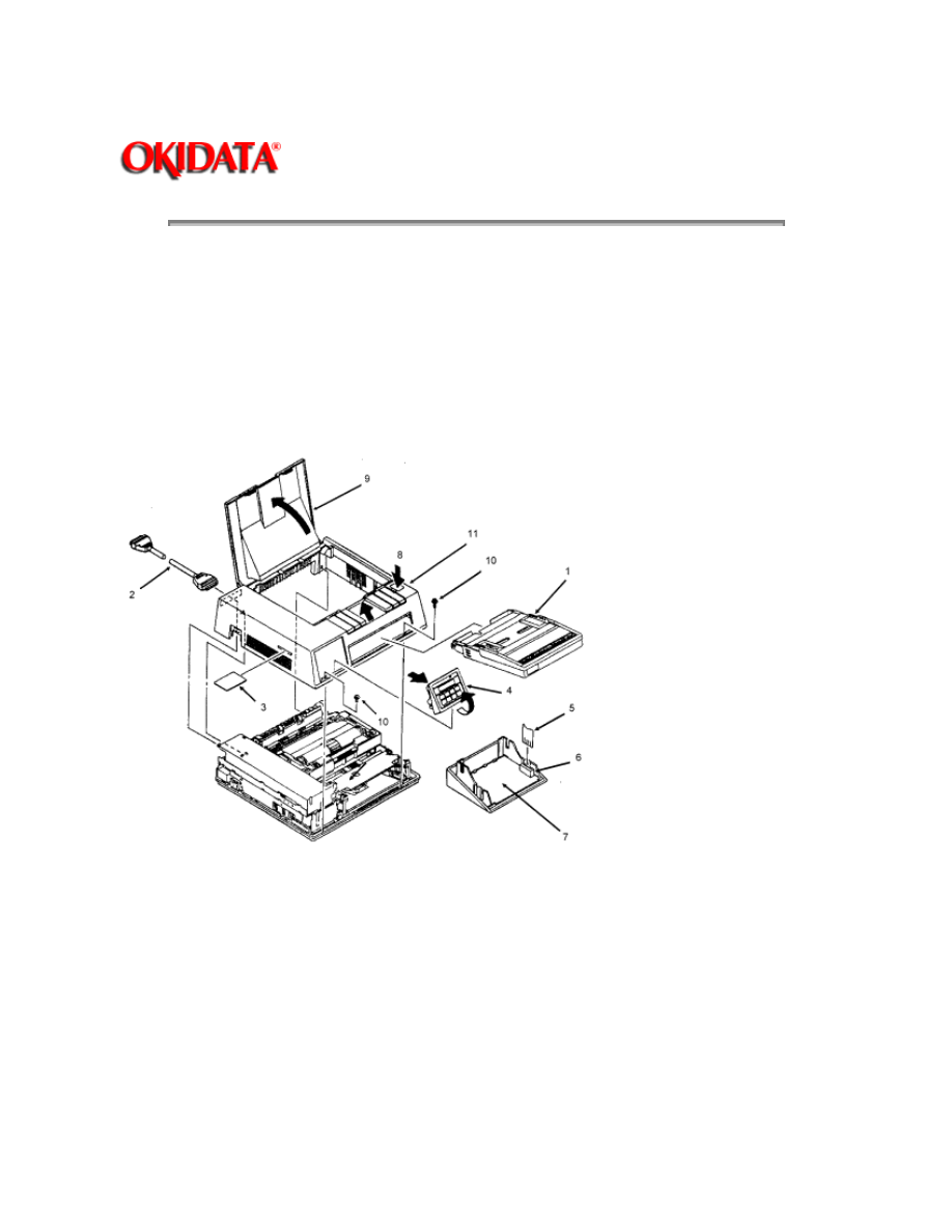
3.2.01 Upper Cover
1. Turn the power switch
OFF
and unplug the AC power cord from the outlet and the printer
power receptacle at the rear of the printer.
2. Remove the paper tray (1), interface cable (2), and font card (3) (if installed).
3. Lift the operator panel assembly (4) at its bottom and detach it.
4. Pull on the locking collar and then detach the connecting cable (5) from connector J1 (6) of the
operator panel PCB (7).
NOTE:
5. Please note that when assembling the operator panel board, you must install the connecting
cable with the blue strip to the left.
6. Press the "OPEN" button (8) and raise the stacker cover (9).
7. Remove the two screws (10) and lift the front side of the upper cover (11). As you lift, you will
disengage the upper cover from the lower cover at the back of the printer.
NOTE:
Installation

Open the stacker cover.
Align the square slots of the upper cover with the claws of the lower cover. The claws are located
on the back of the lower cover, at the left and right sides.
Lower the upper cover into position.
If the cover is not installed properly, paper jams will result.
Copyright 1997, Okidata, Division of OKI America, Inc. All rights reserved. See the OKIDATA Business
Partner Exchange (BPX) for any updates to this material. (http://bpx.okidata.com)
Page: 38
Service Guide OL400
Chapter 3 Maintenance & Disassembly
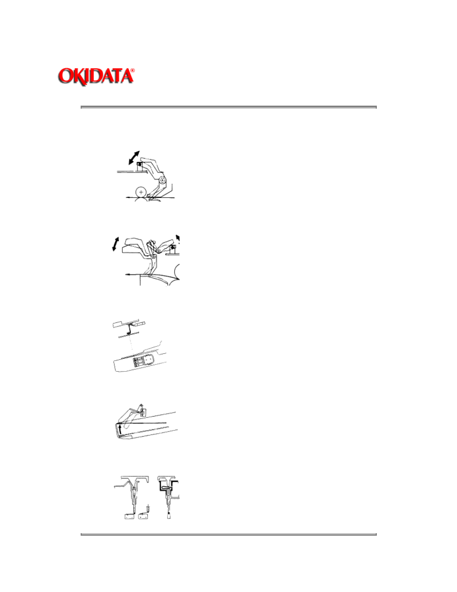
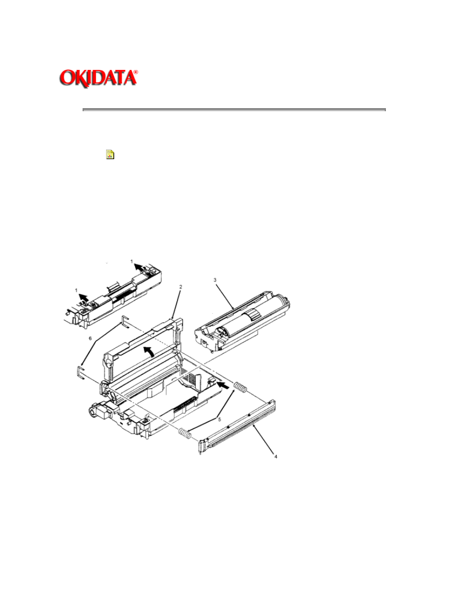
3.2.02 LED Head
1. Perform this procedure:
3.2.01{
}
2. Push the two blue lock levers (1) toward the rear of the printer and open the LED holder (2).
3. Lift and remove the image drum cartridge (3). To protect the image drum cartridge, please
place it back in the styrofoam shipping package.
4. Squeeze the LED head (4) and the LED holder together to ease the tension on the springs (5).
Use a screwdriver to remove the two clamps (6) from the claws of the LED head. The claws are
located on the top and bottom of the left and right sides of the holder.
5. Gradually remove the LED head, being careful to keep the springs in place.
NOTE:
LED Head Replacement
After replacing the LED head, set the LED head drive time as described in Section 3.3 of this
Service Handbook.
{ }

Copyright 1997, Okidata, Division of OKI America, Inc. All rights reserved. See the OKIDATA Business
Partner Exchange (BPX) for any updates to this material. (http://bpx.okidata.com)
Page: 39
Service Guide OL400
Chapter 3 Maintenance & Disassembly
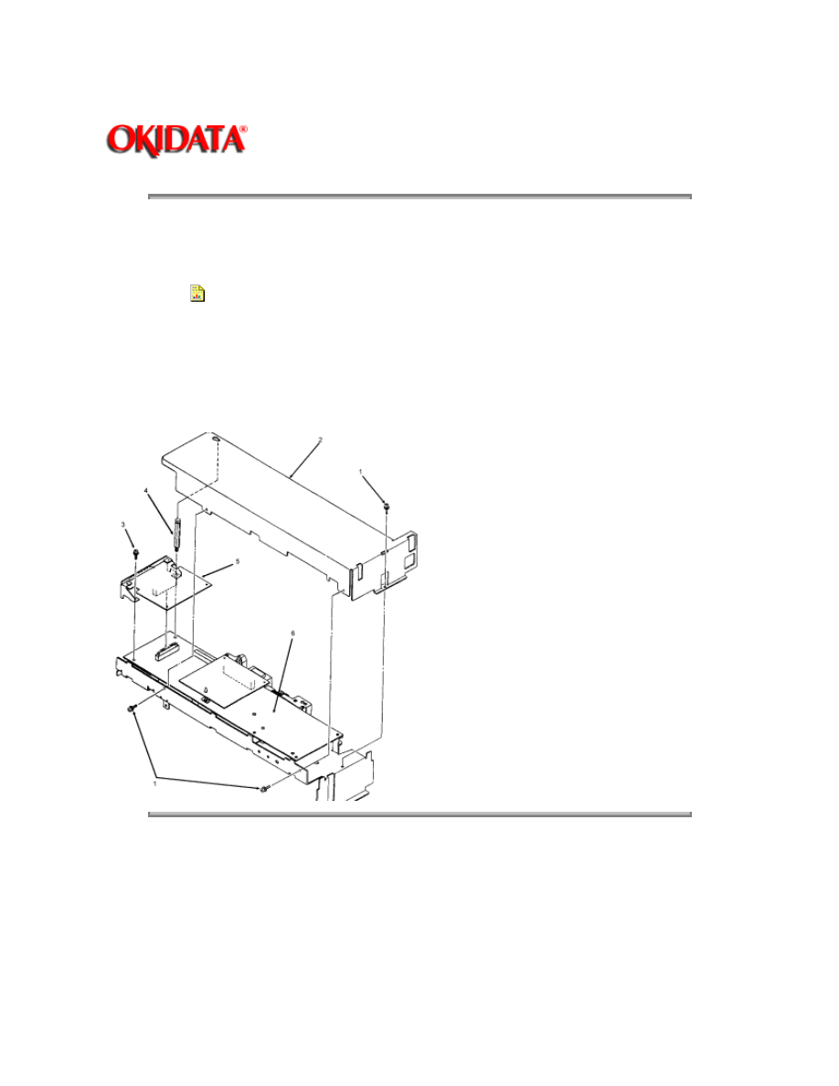
3.2.03 Interface Board
This procedure may be used to remove both the parallel and serial interface boards.
1. Perform this procedure:
3.2.01{
}
2. Remove the three shield cover mounting screws (1) and detach the shield cover (2) by sliding
it forward and lifting it.
3. Remove the interface board mounting screw (3) and the post (4).
4. Lift the interface board (5) to disconnect it from the control board (6) for removal.
Copyright 1997, Okidata, Division of OKI America, Inc. All rights reserved. See the OKIDATA Business
Partner Exchange (BPX) for any updates to this material. (http://bpx.okidata.com)
Page: 40
Service Guide OL400
Chapter 3 Maintenance & Disassembly
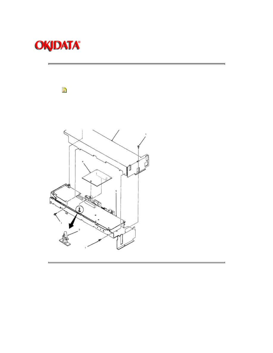
3.2.04 RAM Board (Option)
1. Perform this procedures:
3.2.01{
}
2. Remove the three shield cover mounting screws (1) and detach the shield cover (2) by sliding
it forward and lifting it.
3. Press the hook of the locking circuit board support (3) to unlock the RAM board (4).
4. Lift the RAM board to disconnect it from the main controller board (5) for removal.
Copyright 1997, Okidata, Division of OKI America, Inc. All rights reserved. See the OKIDATA Business
Partner Exchange (BPX) for any updates to this material. (http://bpx.okidata.com)
Page: 41
Service Guide OL400
Chapter 3 Maintenance & Disassembly
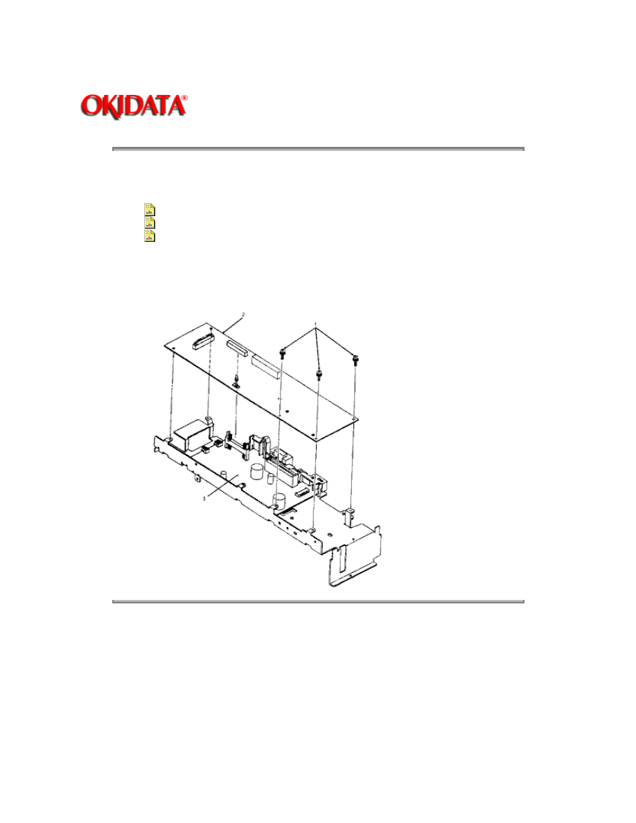
3.2.05 Main Controller Board
1. Perform these procedures:
3.2.01{
}
3.2.03{
}
3.2.04{
}
2. Remove the three controller board mounting screws (1).
3. Lift the main controller board (2) to disconnect it from the engine control circuit board (3) and
remove the main controller board.
Copyright 1997, Okidata, Division of OKI America, Inc. All rights reserved. See the OKIDATA Business
Partner Exchange (BPX) for any updates to this material. (http://bpx.okidata.com)

Page: 42
Service Guide OL400
Chapter 3 Maintenance & Disassembly
3.2.06 Engine Controller Circuit Board (LLAB)
1. Perform these procedures:
3.2.01{
}
3.2.03{
}
3.2.04{
}
3.2.05{
}
2. Disconnect the cables (1) from connectors J1, J2, and J5.
3. Open the LED holder to allow access to the engine board mounting screw (2) and remove the
mounting screw.
4. Close the LED holder and raise the upper unit.
5. Remove the two remaining mounting screws (3).
CAUTION:
Be careful not to lose the plastic spacer (4) located between the shield frame and the engine
controller board. When installing the engine controller board, be sure that the spacer is in place or
the engine controller board will short against the shield frame.
6. Lift the engine controller board (5) to disconnect it from the interconnect board (6).
7. On the engine controller board, press the pawls (7) to unlock and remove the print board cover
(8).
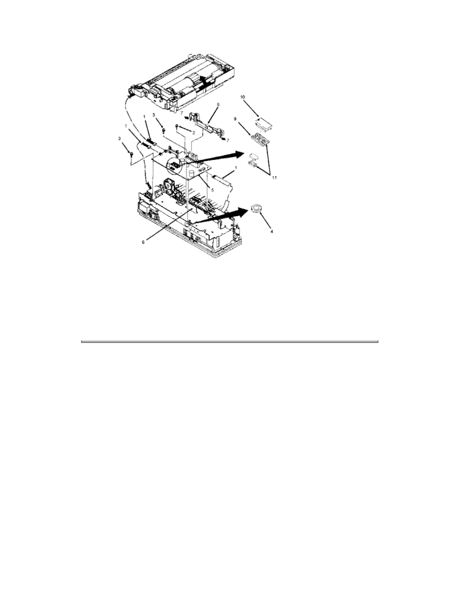
NOTE:
Replacement
When replacing an engine controller board, remove the EEPROM IC2 (9) and the Program PROM
Q1 (10) from the old board and mount them on the new board. With LLAB Revision 11, Q1 is not
installed because the program is masked in the CPU.
Copyright 1997, Okidata, Division of OKI America, Inc. All rights reserved. See the OKIDATA Business
Partner Exchange (BPX) for any updates to this material. (http://bpx.okidata.com)

Page: 43
Service Guide OL400
Chapter 3 Maintenance & Disassembly
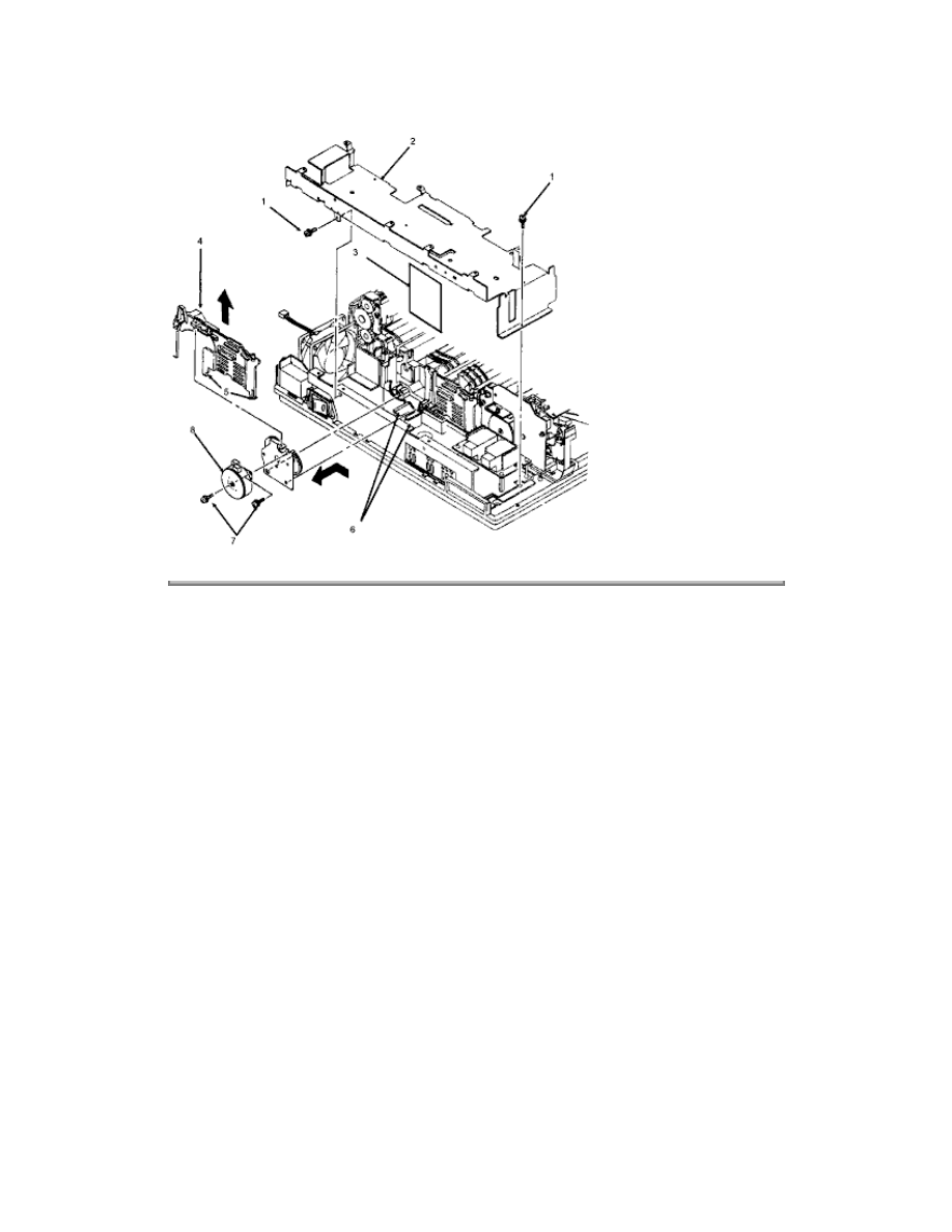
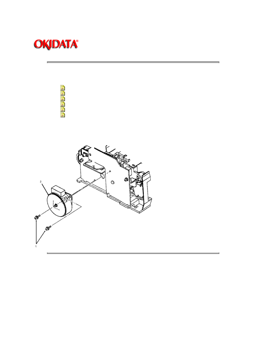
3.2.07 Main Motor
1. Perform these procedures:
3.2.01{
}
3.2.03{
}
3.2.04{
}
3.2.05{
}
3.2.06{
}
2. Remove the three mounting screws (1) and detach the shield frame (2).
3. Detach the interconnect board (3).
NOTE:
The traces which run the entire length of the board are to the front of the printer when the board is
installed.
4. Working from the bottom of the printer, remove the motor cover (4) by releasing the two black
claws (5).
5. Remove the two high voltage wires from the motor cover.
6. Shift the motor assembly to the left to remove it from the claws (6) of the lower unit.
7. Working on the motor assembly, remove the two mounting screws (7) to remove the main
motor (8) from the motor assembly.
`
Copyright 1997, Okidata, Division of OKI America, Inc. All rights reserved. See the OKIDATA Business
Partner Exchange (BPX) for any updates to this material. (http://bpx.okidata.com)
Page: 44
Service Guide OL400
Chapter 3 Maintenance & Disassembly
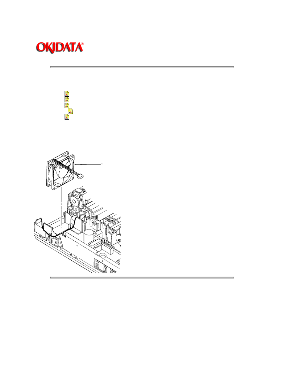
3.2.08 DC Fan Assembly
1. Perform these procedures:
3.2.01{
}
3.2.03{
}
3.2.04{
}
3.2.05{
}
3.2.06{
}
2. Detach the shield frame (3.2.07 step 6).
3. Remove the DC fan assembly (1).
Copyright 1997, Okidata, Division of OKI America, Inc. All rights reserved. See the OKIDATA Business
Partner Exchange (BPX) for any updates to this material. (http://bpx.okidata.com)
Page: 45
Service Guide OL400
Chapter 3 Maintenance & Disassembly
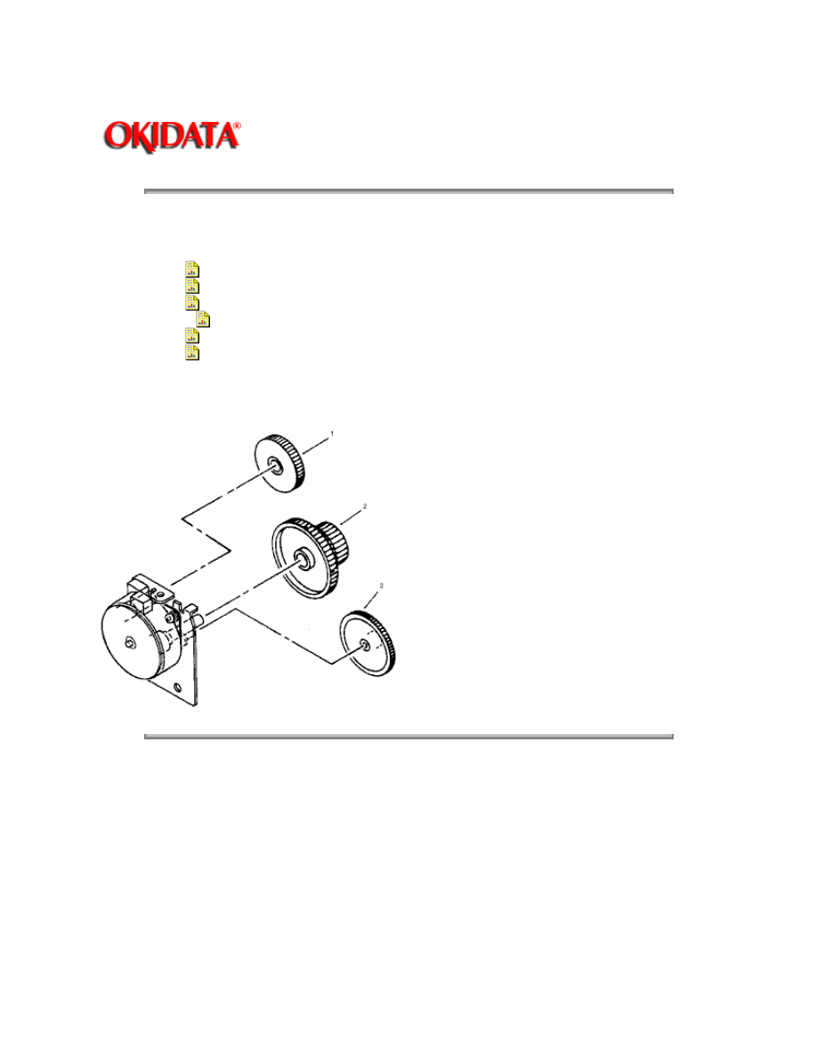
3.2.09 Idle Gears "A" and "B", and the Reduction Gear
1. Perform these procedures:
3.2.01{
}
3.2.03{
}
3.2.04{
}
3.2.05{
}
3.2.06{
}
3.2.07{
}
2. Detach the gears in the following order: idle gear "B" (1), reduction gear (2) and idle gear "A"
(3).
Copyright 1997, Okidata, Division of OKI America, Inc. All rights reserved. See the OKIDATA Business
Partner Exchange (BPX) for any updates to this material. (http://bpx.okidata.com)
Page: 46
Service Guide OL400
Chapter 3 Maintenance & Disassembly
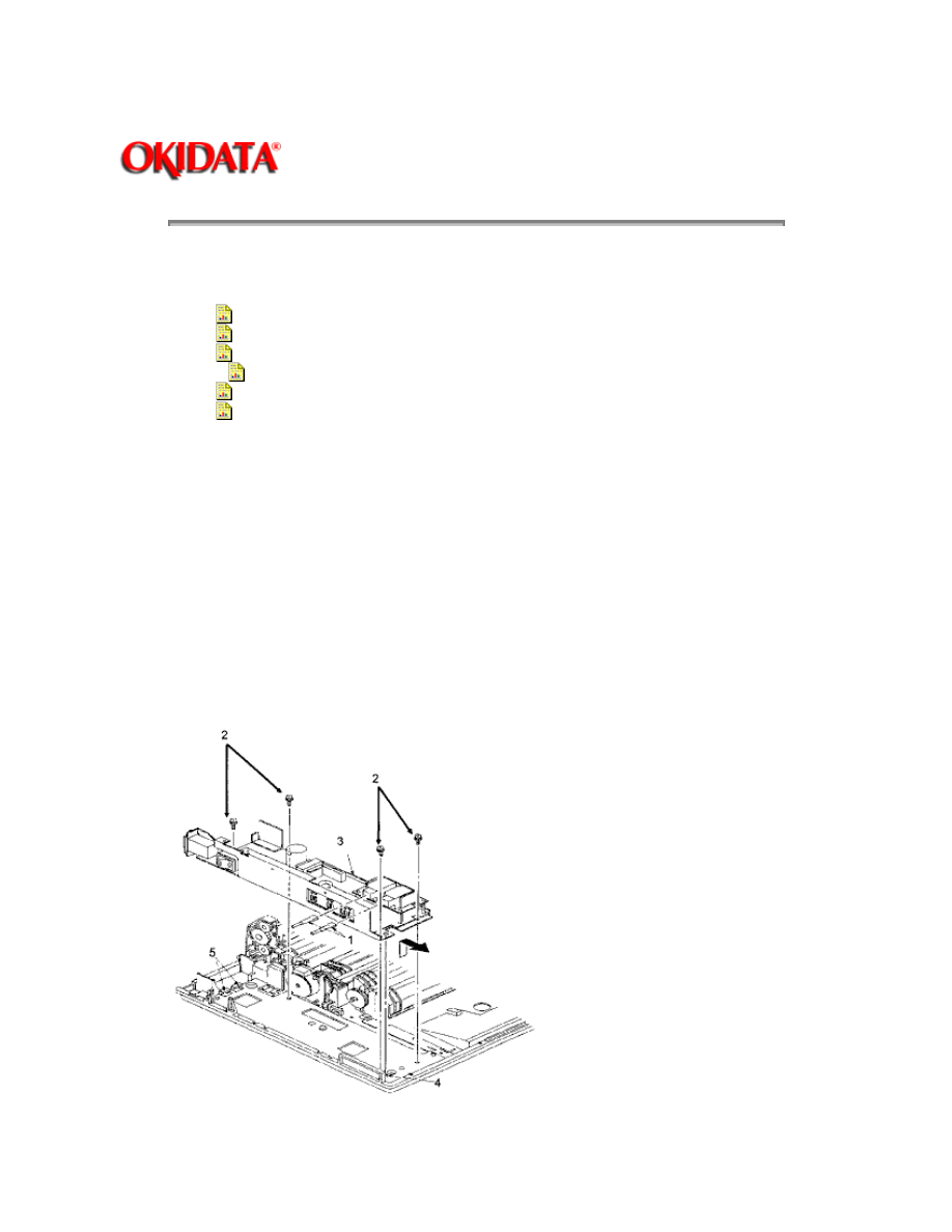
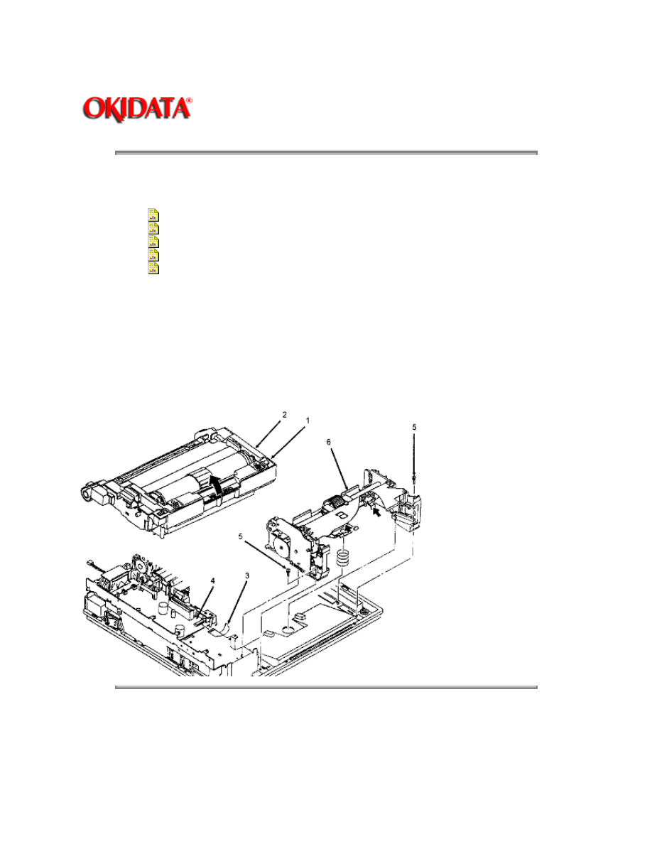
3.2.10 Power Supply Unit
1. Perform these procedures:
3.2.01{
}
3.2.03{
}
3.2.04{
}
3.2.05{
}
3.2.06{
}
3.2.07{
}
2. Disconnect the two high-voltage cables (1).
NOTE:
When installing, the cables are keyed for correct placement. The larger connector is to the front of
the printer.
3. Remove the four mounting screws (2).
4. Raise the upper unit.
5. Slide the power supply unit (3) towards the front until it comes off the guide (4) of the lower
unit.
6. Lift the power supply unit towards you to detach it from the rear claws (5) for removal.

Copyright 1997, Okidata, Division of OKI America, Inc. All rights reserved. See the OKIDATA Business
Partner Exchange (BPX) for any updates to this material. (http://bpx.okidata.com)

Page: 47
Service Guide OL400
Chapter 3 Maintenance & Disassembly
3.2.11 Upper Unit
1. Perform these procedures:
3.2.01{
}
3.2.02{
}
3.2.03{
}
3.2.04{
}
3.2.05{
}
3.2.06{
}
3.2.07{
}
3.2.08{
}
3.2.10{
}
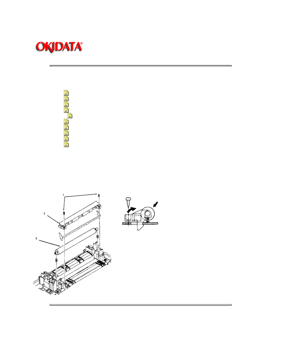
2. Place the face-up stacker assembly, located at the rear of the printer, down. Then, lift the
upper unit.
3. Remove the paper eject roller assembly mounting screw (1). Slightly lift the paper eject roller
assembly (2) at its left end and slide the left end backward using the right end as a pivot. Remove
the assembly.
4. Remove the tension springs (3) using a needle nose pliers.
5. Loosen the two mounting screws (4). Lift the upper unit (5).
6. Slide the upper unit to the right and work it free of the right slot to remove it.
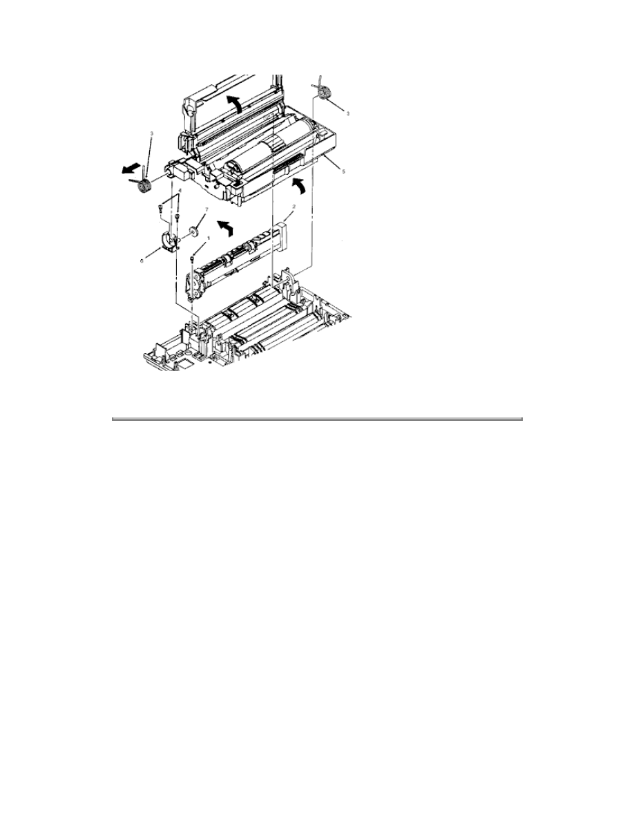
CAUTION:
Be careful not to drop the fulcrum block (6) and the idle gear (7) when removing the upper unit.
Copyright 1997, Okidata, Division of OKI America, Inc. All rights reserved. See the OKIDATA Business
Partner Exchange (BPX) for any updates to this material. (http://bpx.okidata.com)

Page: 48
Service Guide OL400
Chapter 3 Maintenance & Disassembly
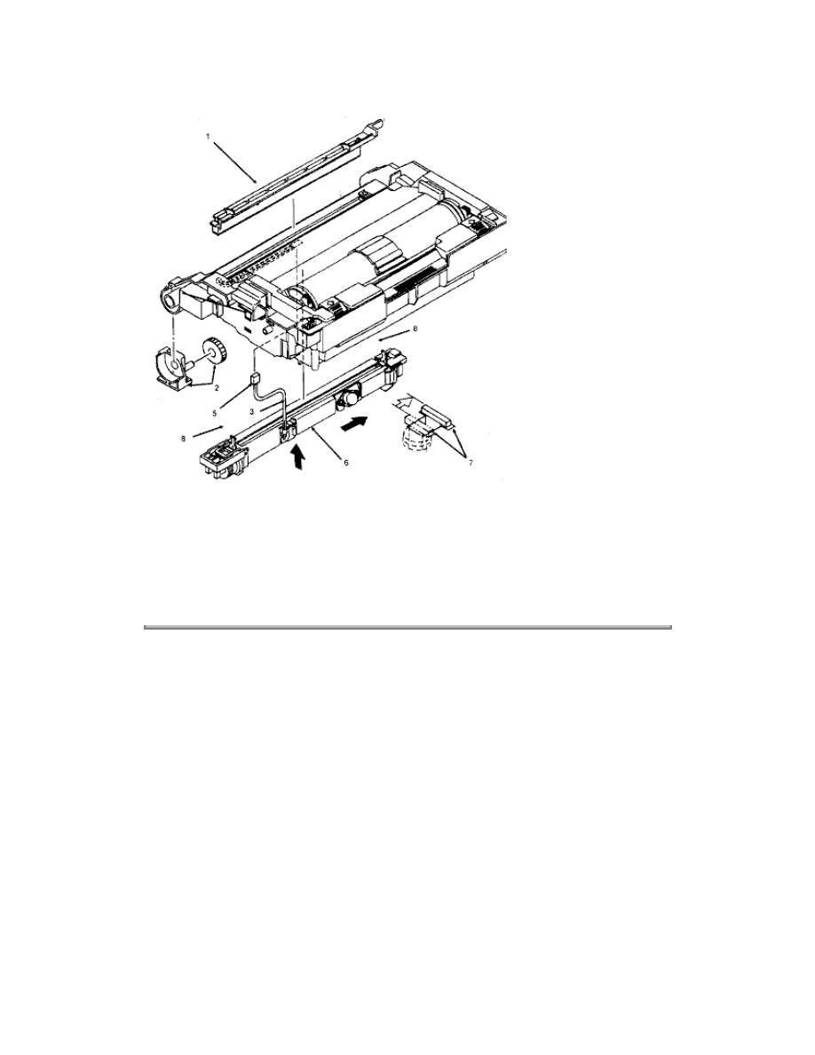
3.2.12 Fusing Unit
WARNING:
Allow the printer to cool before servicing the fusing unit.
1. Perform these procedures:
3.2.01{
}
3.2.02{
}
3.2.03{
}
3.2.04{
}
3.2.05{
}
3.2.06{
}
3.2.07{
}
3.2.08{
}
3.2.10{
}
3.2.11{
}
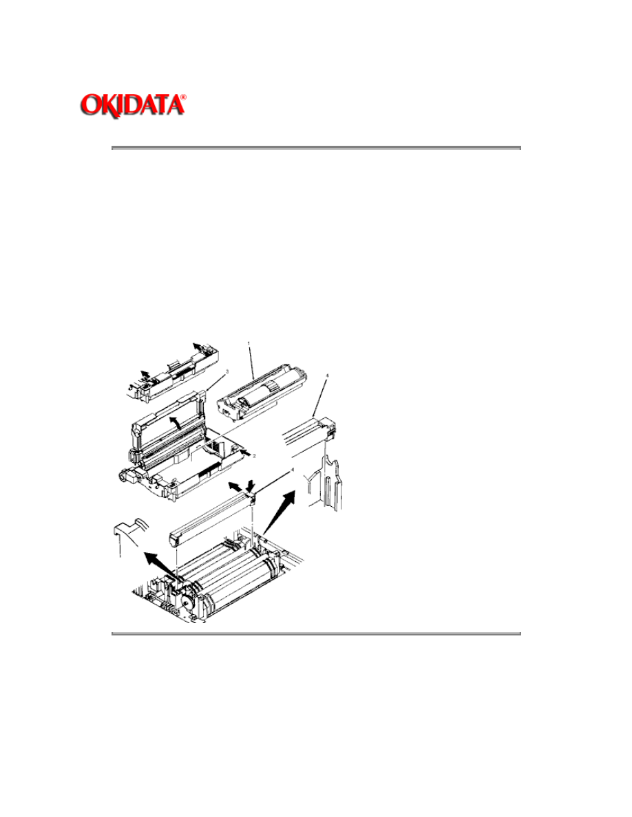
2. Working on the upper unit, remove fuser cleaner pad (1) and the fulcrum block with idle gear
(2).
3. Detach the cable (3) from the cable guide (4) of the upper unit.
4. Pass the connector (5) through the slot in the upper unit and work the cable from the upper unit
guides.
5. Position the upper unit so its underside is facing you, with the fusing unit (6) at the top.
6. Push the fusing unit against the upper unit until the two lock plates (7) protrude from their slots.
7. Slide the fusing unit to the right until the lock plates disengage from the grooves of the upper
unit.
8. Remove the fusing unit, being careful not to lose the springs (8).
CAUTION:
Installation
The four separator claws must move freely within their grooves or paper jams will result.
Copyright 1997, Okidata, Division of OKI America, Inc. All rights reserved. See the OKIDATA Business
Partner Exchange (BPX) for any updates to this material. (http://bpx.okidata.com)
Page: 49
Service Guide OL400
Chapter 3 Maintenance & Disassembly
3.2.13 Backup Roller
1. Perform these procedures:
3.2.01{
}
3.2.02{
}
3.2.03{
}
3.2.04{
}
3.2.05{
}
3.2.06{
}
3.2.07{
}
3.2.08{
}
3.2.10{
}
3.2.11{
}
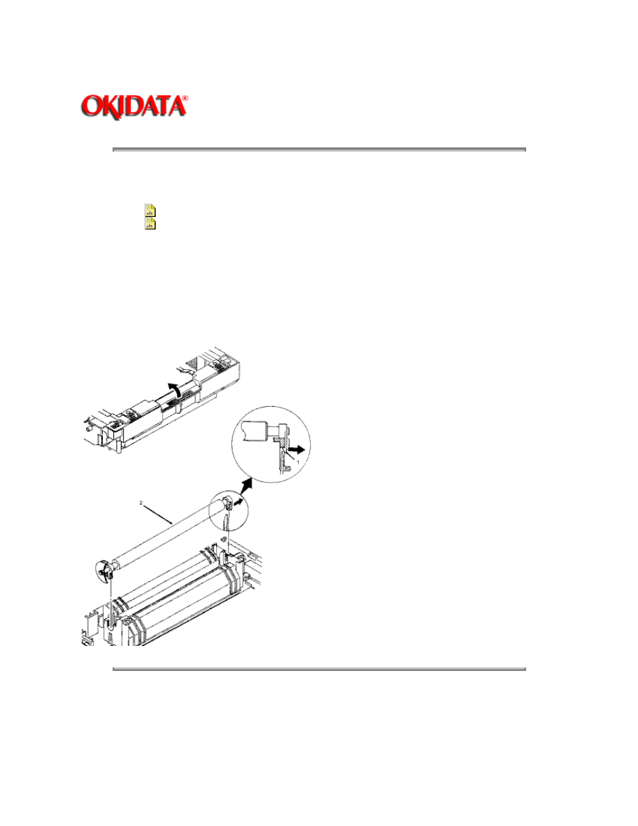
2. Remove the two mounting screws (1).
3. Use a straight slot screwdriver to detach the sheet guide (2).
4. Remove the backup roller (3).
Copyright 1997, Okidata, Division of OKI America, Inc. All rights reserved. See the OKIDATA Business
Partner Exchange (BPX) for any updates to this material. (http://bpx.okidata.com)
Page: 50
Service Guide OL400
Chapter 3 Maintenance & Disassembly
3.2.14 Transfer Charger Assembly
1. Turn the power switch OFF and unplug the AC power cord from the outlet.
2. Press the OPEN button and raise the stacker cover.
3. Remove the image drum cartridge (1). (See 3.2.2)
4. Push the lock lever (2) towards the back of the printer to raise the upper unit (3).
5. Firmly push down and back on the sides of the transfer charger assembly (4) until the lower
cover claws are disengaged from the square holes on each end of the transfer charger assembly.
6. Lift and remove the transfer charger assembly.
Copyright 1997, Okidata, Division of OKI America, Inc. All rights reserved. See the OKIDATA Business
Partner Exchange (BPX) for any updates to this material. (http://bpx.okidata.com)
Page: 51
Service Guide OL400
Chapter 3 Maintenance & Disassembly
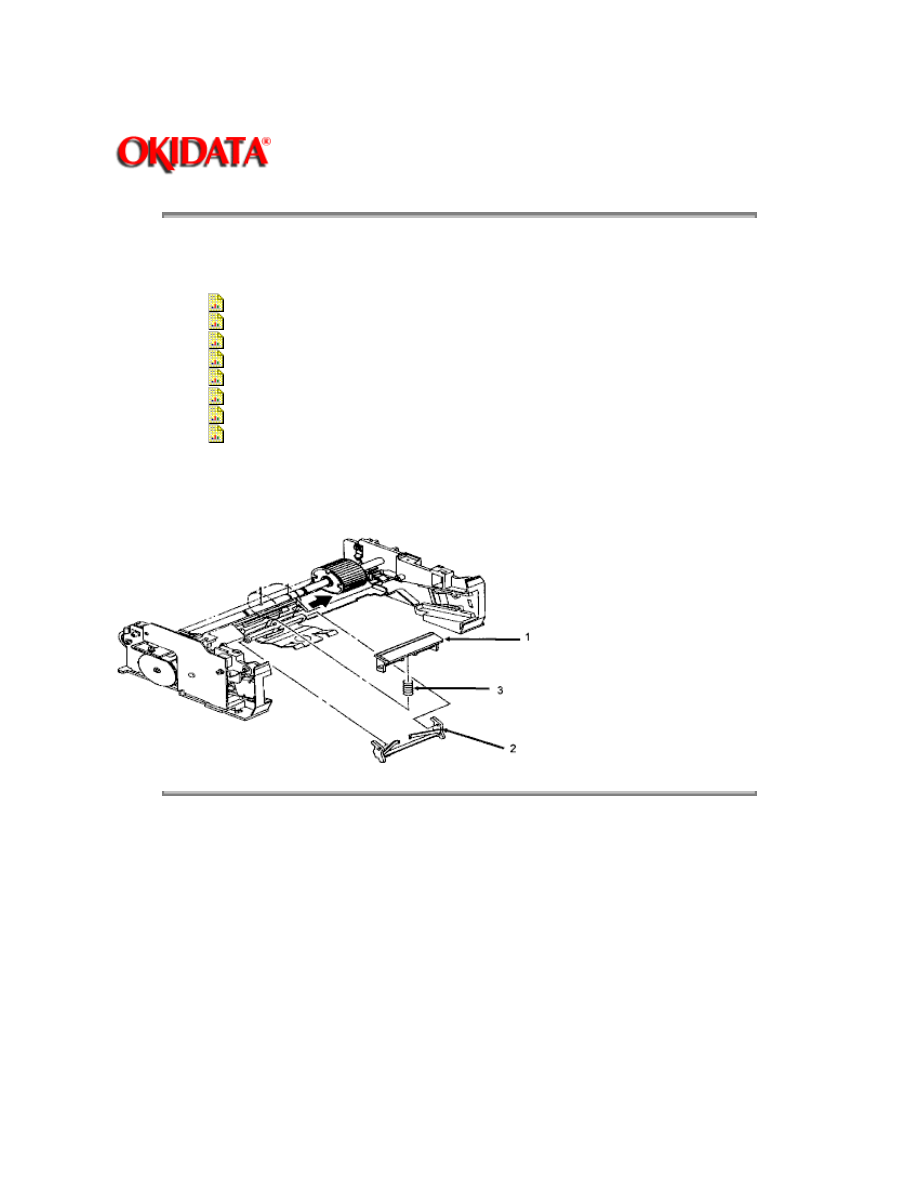
3.2.15 Resist Roller Assembly
1. Perform these procedures:
3.2.01{
}
3.2.02{
}
2. Using a standard screwdriver, release the claws (1) from both sides of the resist roller
assembly (2).
NOTE:
The left claw can be accessed from the bottom of the printer.
3. Lift the resist roller assembly from the printer.
Copyright 1997, Okidata, Division of OKI America, Inc. All rights reserved. See the OKIDATA Business
Partner Exchange (BPX) for any updates to this material. (http://bpx.okidata.com)
Page: 52
Service Guide OL400
Chapter 3 Maintenance & Disassembly
3.2.16 Idle Gear C
1. Perform this procedure:
3.2.01{
}
2. Push the lock lever towards the back of the printer to raise the upper unit.
3. Using a needle nose pliers and working from the left side of the printer, push the post (1) to the
right.
4. Remove the post.
5. Remove idle gear C (2).
NOTE:
The cutout (3) on the post should be positioned to the left side of the printer and on the top when
installing.
Copyright 1997, Okidata, Division of OKI America, Inc. All rights reserved. See the OKIDATA Business
Partner Exchange (BPX) for any updates to this material. (http://bpx.okidata.com)
Page: 53
Service Guide OL400
Chapter 3 Maintenance & Disassembly
3.2.17 Paper Supply Unit
1. Perform these procedures:
3.2.01{
}
3.2.02{
}
3.2.03{
}
3.2.04{
}
3.2.05{
}
2. Press the lock lever (1) backward and lift the upper unit (2).
3. Disconnect the cable (3) from connector J5 on the engine controller circuit board (4).
4. Remove the two mounting screws (5).
5. Lift the paper supply assembly (6) at its front until the frame of the unit comes off the guide
pins, then move the unit towards you for removal.
Copyright 1997, Okidata, Division of OKI America, Inc. All rights reserved. See the OKIDATA Business
Partner Exchange (BPX) for any updates to this material. (http://bpx.okidata.com)
Page: 54
Service Guide OL400
Chapter 3 Maintenance & Disassembly
3.2.18 Resist Motor
1. Perform these procedures:
3.2.01{
}
3.2.02{
}
3.2.03{
}
3.2.04{
}
3.2.05{
}
3.2.17{
}
2. Remove the two mounting screws (1).
3. Detach the resist motor (2).
Copyright 1997, Okidata, Division of OKI America, Inc. All rights reserved. See the OKIDATA Business
Partner Exchange (BPX) for any updates to this material. (http://bpx.okidata.com)
Page: 55
Service Guide OL400
Chapter 3 Maintenance & Disassembly
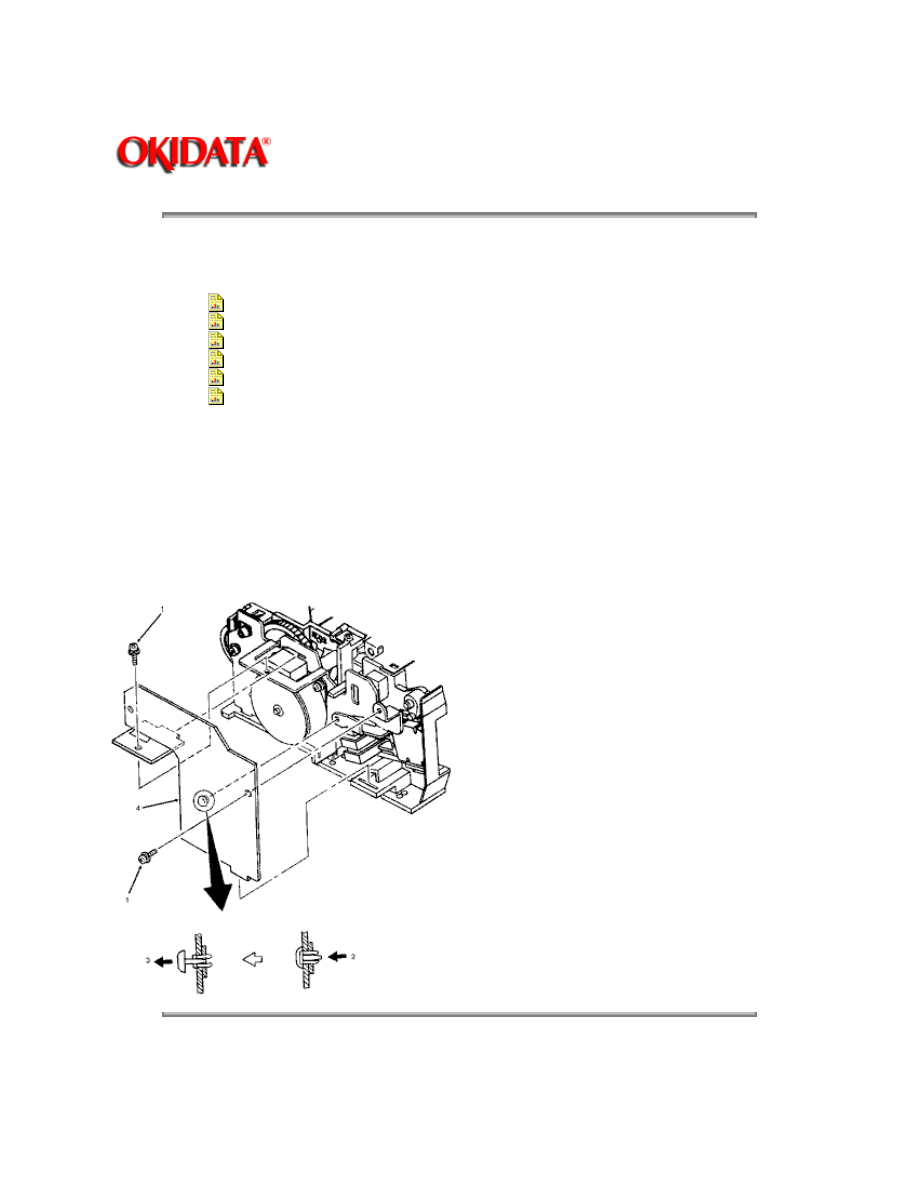
3.2.19 Engine Connection Board
1. Perform these procedures:
3.2.01{
}
3.2.02{
}
3.2.03{
}
3.2.04{
}
3.2.05{
}
3.2.17{
}
2. Remove the two mounting screws. (1)
3. On the paper supply unit, press the pointed end of the nylon latch (2), push out the head (3),
and remove the latch.
4. Detach the engine connection board (4).
Copyright 1997, Okidata, Division of OKI America, Inc. All rights reserved. See the OKIDATA Business
Partner Exchange (BPX) for any updates to this material. (http://bpx.okidata.com)
Page: 56
Service Guide OL400
Chapter 3 Maintenance & Disassembly
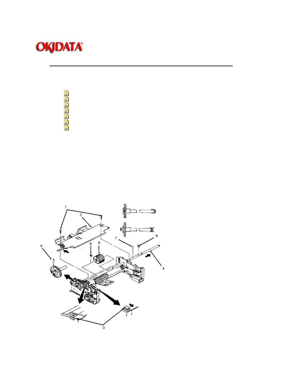
3.2.20 Hopping Roller
1. Perform these procedures:
3.2.01{
}
3.2.02{
}
3.2.03{
}
3.2.04{
}
3.2.05{
}
3.2.15{
}
3.2.17{
}
2.
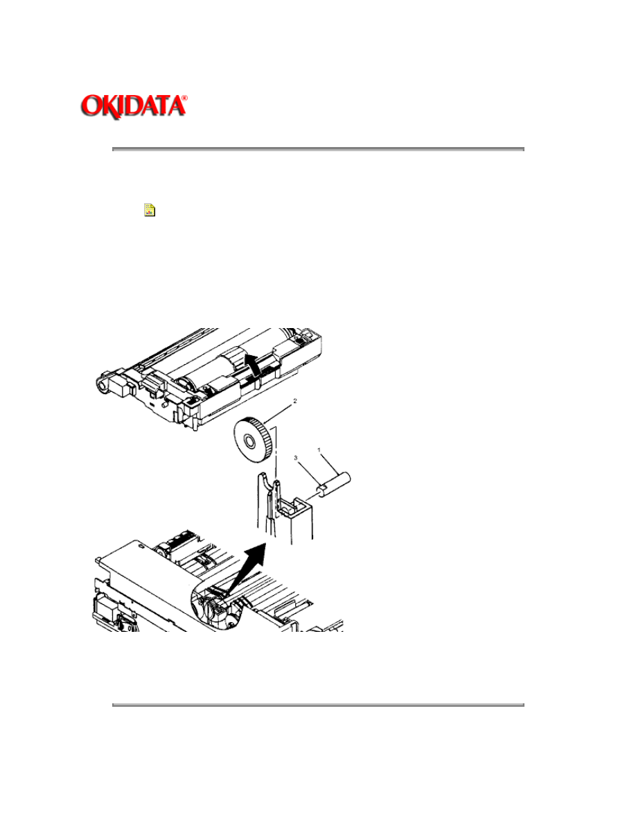
Remove the two screws (1) and slide the upper plate assembly (2) until the claws (3) are
unlocked.
3. Push the hopping roller shaft (4) to the left to unlock it.
4. Remove the hopping gear pin (5).
5. Remove the E-clips (6).
6. Remove the hopping roller pin (7).
7. Slide the hopping roller shaft to the right and remove the hopping roller (8).

NOTE:
When installing, always mount the hopping roller shaft above the ground plate, which is on
the left side of the printer.
Copyright 1997, Okidata, Division of OKI America, Inc. All rights reserved. See the OKIDATA Business
Partner Exchange (BPX) for any updates to this material. (http://bpx.okidata.com)
Page: 57
Service Guide OL400
Chapter 3 Maintenance & Disassembly
3.2.21 Separator
1. Perform these procedures:
3.2.01{
}
3.2.02{
}
3.2.03{
}
3.2.04{
}
3.2.05{
}
3.2.15{
}
3.2.17{
}
3.2.20{
}
2. Hold the separator (1) down and remove the escape lever (2) from the pins on the paper
supply unit. Be careful not to lose the separator spring (3).
Copyright 1997, Okidata, Division of OKI America, Inc. All rights reserved. See the OKIDATA Business
Partner Exchange (BPX) for any updates to this material. (http://bpx.okidata.com)
Page: 58
Service Guide OL400
Chapter 3 Maintenance & Disassembly
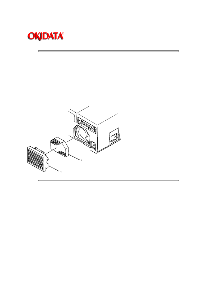
3.2.22 Ozone Filter
NOTE:
An ozone filter is provided with the image drum cartridge kit. The filter should be replaced when
the image drum cartridge is replaced.
Using a screwdriver, insert the blade under the lower portion of the fan cover (1) and twist the
screwdriver to remove the fan cover.
Remove the ozone filter (2) from the fan cover.
Copyright 1997, Okidata, Division of OKI America, Inc. All rights reserved. See the OKIDATA Business
Partner Exchange (BPX) for any updates to this material. (http://bpx.okidata.com)

Page: 59
Service Guide OL400
Chapter 3 Maintenance & Disassembly
3.3
ADJUSTMENTS AND SERVICE CHECKS
3.3.01 General Information
The first four adjustments (Actual Page Count, Modified Page Count, Vertical Print Start Position
and LED Head Drive Time) are performed by changing addresses on the EEPROM located on the
Engine Controller printed circuit board.
Before performing these adjustments, setup the printer as listed below.
1. Remove the upper cover.
2. Raise the upper unit.
3. Remove the image drum cartridge.
4. Override the cover open interlock switch.
Copyright 1997, Okidata, Division of OKI America, Inc. All rights reserved. See the OKIDATA Business
Partner Exchange (BPX) for any updates to this material. (http://bpx.okidata.com)

Page: 60
Service Guide OL400
Chapter 3 Maintenance & Disassembly
3.3.02 Actual Page Count
General Information
The actual page counter counts the number of sheets printed by the printer.
Procedure
To display the value of the actual page counter, follow this procedure.
1. Power ON the printer while pressing Switch 1 on the Engine Controller Board. The LED
(located on the Engine Controller Board) will flash once - then pause (the LED will continuously
flash once - then pause) indicating that the printer is in Parameter 1 of the maintenance mode.
2. Press Switch 1 for five seconds. The LED will display the contents of the Parameter1 (Actual
Page Counter) register as follows:
a.
The long flash indicates start of count.
b.
Short flashes indicate counter contents (most significant digit first). There will be a
pause between digits.
c.
Upon completion of the count,a long flash will indicate start of count.
d.
This process will loop until you press Switch 1 for five seconds. This will cause
the
modified page count to be displayed. (refer to 3.3.02)
Example
Actual Page Counter = 235 pages
Copyright 1997, Okidata, Division of OKI America, Inc. All rights reserved. See the OKIDATA Business
Partner Exchange (BPX) for any updates to this material. (http://bpx.okidata.com)

Page: 61
Service Guide OL400
Chapter 3 Maintenance & Disassembly
3.3.03 Modified Page Count
General Information
The modified page counter combines the main motor revolution time and the number of printed
sheets. Drum replacement is determined by the modified page count.
Procedure
To check the modified page count, follow this procedure.
NOTE:
To access the Modified Page Count, you must first view the Actual Page Count.
1.
After viewing the Actual Page Count, press Switch 1 for five seconds. The LED
will
display the contents of the Parameter 1 (Modified Page Count) register.
2.
To end this procedure, press Switch 1 for 1 second. The LED will perform one
short flash to indicate Parameter 1 is selected.
Example
Modified Page Counter = 142
The next step in this table is also the last step in the Actual Page Counter Table
Switch 1 Action
LED Display
Description
Press for 5 seconds
Long Flash
Start of Modified Page Count
None
On-Off-Pause
1st Digit = 1
None
On-Off-On-Off-On-Off-On-Pause
2nd Digit = 4
None
On-Off-On-Off-Pause
3rd Digit = 2
None
Long Flash
Start of Count
Press for 1 second
Flashes ON/OFF
Parameter #1 - Selected
NOTE:
The number "0" is represented by 10 flashes
The Actual and Modified Page Counters CANNOT be changed.
Copyright 1997, Okidata, Division of OKI America, Inc. All rights reserved. See the OKIDATA Business
Partner Exchange (BPX) for any updates to this material. (http://bpx.okidata.com)

Page: 62
Service Guide OL400
Chapter 3 Maintenance & Disassembly
3.3.04 Vertical Print Start Position Adjustment
General Information
The Vertical Print Start Position Adjustment is used to set the top of form position. Use this
adjustment to correct print start variations between different OL400 printers, or to achieve a 4.6
mm vertical start position, the default value.
A chart of the EEPROM addresses and print start positions is shown below.
The Vertical Print Start Position is Parameter 9.
Procedure
1. To change the Vertical Print Start Position, follow this procedure.
2. Power ON the printer while pressing Switch 1 on the Engine Control board. The LED will flash
continuously, indicating that the printer is in Parameter 1 of the maintenance mode.
3. Press Switch 1 eight times to access Parameter 9. The LED will flash 9 times, indicating
Parameter 9 has been selected.
4. Press Switch 1 once for 5 seconds. The contents of the Parameter 9 register will be displayed.
5. To modify the contents of the Parameter 9 register, press Switch 1 (momentarily) to step
through the addresses (in accordance with the chart shown below).
6. To end the adjustment, press Switch 1 once for 5 seconds. The LED will flash 9 times,
indicating Parameter 9.
NOTE:
Ten flashes represent the number zero.
On the table below, Address 0 comes after Address 15
EEPROM Address / Print Start Position Table
EEPROM
Address
Print Start Position
(in mm)
EEPROM
Address
Print Start Position
(in mm)
0 DEFAULT
0
8
-4.0
1
+.5
9
-3.5

2
+1.0
10
-3.0
3
+1.5
11
-2.5
4
+2.0
12
-2.0
5
+2.5
13
-1.5
6
+3.0
14
-1.0
7
+3.5
15
-0.5
Copyright 1997, Okidata, Division of OKI America, Inc. All rights reserved. See the OKIDATA Business
Partner Exchange (BPX) for any updates to this material. (http://bpx.okidata.com)
Page: 63
Service Guide OL400
Chapter 3 Maintenance & Disassembly
3.3.05 Setting the LED Head Drive Time
General Information
This adjustment is necessary only when replacing the LED head. However, if the luminous energy
ratings of the new and original LED heads are the same, adjustment is not necessary. The
luminous energy rating is on the label on the LED head. Digits three and two (reading from the
right) are the drive time rating.
The LED Head Drive Time is Parameter 13.
Procedure
To change the LED Head Drive Time, follow this procedure.
1. Power ON the printer while pressing Switch 1 on the Engine Control board. The LED will flash
continuously, indicating that the printer is in Parameter 1 of the maintenance mode.
2. Press Switch 1, twelve times to access Parameter 13. The LED will flash thirteen times,
indicating Parameter 13 has been selected.
3. Press Switch 1 once for five seconds. The contents of the Parameter 13 register will be
displayed.
4. To modify the contents of the Parameter 13 register, press Switch 1 (momentarily) to step
through the addresses (in accordance with the chart shown below).
5. To end the adjustment, press Switch 1 once for five seconds. The LED will flash thirteen times,
indicating Parameter 13.
LED Drive Time Rating / Drive Time Setting Table
Drive Time Rating displayed on
LED Head
Drive Time Setting Value
(Address)
08
5
09
4
10
3
11 12
2
13 14
1

15 16 17
0
18 19 20
15
21 22 23 24
14
25 26 27 28 29
13
30 31 32 33 34 35 36
12
Copyright 1997, Okidata, Division of OKI America, Inc. All rights reserved. See the OKIDATA Business
Partner Exchange (BPX) for any updates to this material. (http://bpx.okidata.com)
Page: 64
Service Guide OL400
Chapter 3 Maintenance & Disassembly
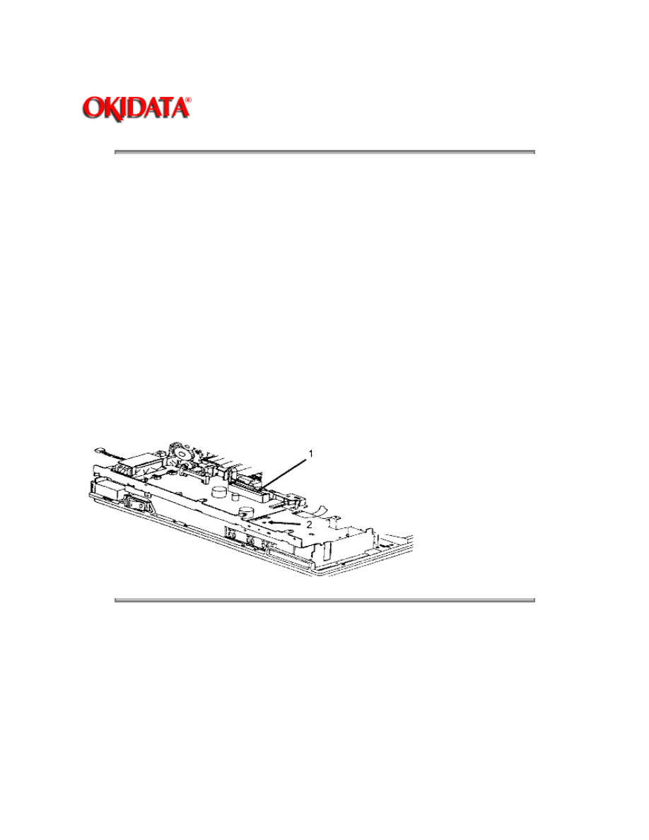
3.3.06 Voltage Adjustment (+5 vdc)
Procedure
1.
Remove the upper cover.
2.
Remove the shield cover.
3.
Remove the main controller board.
4.
Use a digital voltmeter which has an input impedance of 10M Ohms and is capable of
displaying to the second decimal place or farther.
5.
Check the voltage at CN1 of the interconnect board (1) between Pin 31, 5 vdc and
Pin27, 0 vdc .
The value should be +5.0 vdc (+/-0.1).
6.
If adjustment is required, remove the font guide.
7.
Change the output voltage by adjusting potentiometer RV1 on the power supply board (2).
Copyright 1997, Okidata, Division of OKI America, Inc. All rights reserved. See the OKIDATA Business
Partner Exchange (BPX) for any updates to this material. (http://bpx.okidata.com)

Page: 65
Service Guide OL400
Chapter 3 Maintenance & Disassembly
3.3.07 Darkness Control
General Information
The Darkness Control is adjusted from the Level 2 Menu. This adjustment changes the degree of
character density.
Procedure
1. Place the printer off-line.
2. Press and hold
MENU
more than 2 seconds. The first menu category will appear on the
display.
3. Press
MENU
until "Darkness" appears on the display.
4. Press "
+
" to toggle through the values until the desired setting is reached.
5. Press
ENTER/MENU RESET
to store the new setting.
Copyright 1997, Okidata, Division of OKI America, Inc. All rights reserved. See the OKIDATA Business
Partner Exchange (BPX) for any updates to this material. (http://bpx.okidata.com)

Page: 66
Service Guide OL400
Chapter 3 Maintenance & Disassembly
3.4
CLEANING
3.4.01 General Information
Remove any dropped toner and dust. Clean inside and around the printer with a vacuum cleaner
when necessary.
CAUTION:
Do not touch the image drum, the LED head, or the LED head connector block.
3.4.02 Cleaning the Static Charge Wire
1. Turn OFF the power supply switch, and press the "OPEN" button and raise the stacker cover.
2. Push the two lock levers backward and lift the LED holder.
3. Clean the static charge wire by moving the blue wire cleaner of the image drum cartridge to the
left and right.
4. Place the blue wire cleaner in its original position (to the right).
3.4.03 Cleaning the Transfer Charge Wire
CAUTION:
Do not press strongly when cleaning or you will break the transfer wire.
1. Push the two lock levers backward to lift the LED holder, and take out the wire cleaner.
2. Close the LED holder.
3. Raise the upper unit.
4. Clean the transfer charger by pressing the wire cleaner to the transfer charger assembly. Slide
it several times to the left and right, and clean the transfer wire.
5. Return the wire cleaner to its original position.
3.4.04 LED Lens Array
1. Clean the LED lens array when vertical white lines or "blank" spots appear on the output.
2. Place the LED lens cleaner pad against the LED lens array.
3. Slide the cleaner pad horizontally several times to clean the head. Use a clean area of the pad
on each pass.
4. Discard the pad.

Copyright 1997, Okidata, Division of OKI America, Inc. All rights reserved. See the OKIDATA Business
Partner Exchange (BPX) for any updates to this material. (http://bpx.okidata.com)
Page: 67
Service Guide OL400
Chapter 4 Failure & Repair Analysis
4.1
OVERVIEW
4.1.01 Introduction
This section is used to isolate problems to the assembly level. Application problems and detection
of faulty components on the printed circuit boards are not addressed.
When troubleshooting a defective unit,
refer first to Section 4.4{
}
of this Service Handbook. This
section contains tips on preventing problems as well as a list of common problems.
Next,
refer to Section 4.5{
}.
This section lists the operator panel messages and sample output
problems.
Finally,
refer to Section 4.6 {
}.
Repair Analysis Procedures (RAPs) will ask you questions or
require you to make observations. The answers to these questions and the results of your
observations determine your next course of action. Use the RAP Index to identify which RAP
should be used to resolve the problem with the machine.
If you encounter a situation that is not addressed by the documentation in this kit, please report
the problem to Okidata. Refer to the Service Center Reference Guide for information on
contacting Okidata.
The following information is provided to detect and analyze failures.
Okilink II, Faxable Facts, Technical Service Bulletins
Troubleshooting Tips / Common Problems
Fault Alarms
Output Samples
Repair Analysis Procedures*
Tests
Continuous Print
Print Fonts
Menu Print
Serial Interface Loop
Engine
Copyright 1997, Okidata, Division of OKI America, Inc. All rights reserved. See the OKIDATA Business
Partner Exchange (BPX) for any updates to this material. (http://bpx.okidata.com)

Page: 68
Service Guide OL400
Chapter 4 Failure & Repair Analysis
4.2
TROUBLESHOOTING UPDATES
4.2.01 General Information
Okidata distributes updated troubleshooting information in three ways.
Okilink II
Faxable Facts
Technical Service Bulletins
4.2.02 Okilink II
Okilink II is Okidata's Bulletin Board Service. This service is available to all Okidata Certified
Service Technicians. Okilink II provides troubleshooting and service information. Technicians can
download files, ask questions of Okidata's technical support personnel, and participate in round
table discussions about Okidata products and services. Technical Service Bulletins,
Recommended Spare Parts Lists, Printer Drivers, Product Specifications, and Service Training
Information are also available.
Refer to the Service Center Reference Guide { }
for information on accessing Okilink II.
4.2.03 Faxable Facts
Okidata's Faxable Facts is an automated fax document retrieval system. It is maintained by
Okidata's Customer Information Center. Answers to common questions about Okidata products
are available through Faxable Facts.
Refer to the Service Center Reference Guide{ }
for information on accessing Faxable Facts.
4.2.04 Technical Service Bulletins
Okidata's Technical Service Bulletins (TSBs) contain technical information developed after
product release. Firmware updates, part number changes, and procedural changes are some of
the subjects covered by these bulletins. The TSBs are distributed through Okilink II.
Refer to the Service Center Reference Guide { }
for information on accessing Okilink II.
Copyright 1997, Okidata, Division of OKI America, Inc. All rights reserved. See the OKIDATA Business
Partner Exchange (BPX) for any updates to this material. (http://bpx.okidata.com)

Page: 69
Service Guide OL400
Chapter 4 Failure & Repair Analysis
4.3
REPORTING PROBLEMS
4.3.01 General Information
Okidata strives to provide accurate and detailed service information through its training materials.
The Technical Training Group realizes that service technicians have valuable experience,
knowledge, and opinions. Okidata strongly encourages you to report any problems you may
encounter when using the materials of this training kit. Please be as specific and detailed as
possible. Your comments, suggestions, and criticisms are used to update and revise training kits.
You should reference the training materials when servicing Okidata products. Most problems can
be solved by using the information provided in the training materials. If you encounter a situation
that cannot be solved, please let Okidata know.
Refer to the Service Center Reference Guide { }
for information on contacting Okidata.
4.3.02 Problem Lists
Technicians frequently request a list of common problems specific to a product. Technical
Training Kits are written before a product is shipped to customers. Therefore, such information is
not available when a product is first released.
However, Okidata wants to respond to these requests. Okilink II provides round-table discussions
on technical problems. Errors and corrections in the training materials are listed in the Training
Section of Okilink II. The Technical Service Bulletins (also known as Okidata's Monthly Mail) are
available via Okilink II. Situations that are not addressed in the reference documentation, technical
service bulletins, or round tables may be reported to the Dealer Service and Support Engineers
(DSSEs) or the Technical Training Group. You will receive a response to your message within one
business day.
The information on Okilink II is the most accurate and up-to-date technical information available
from Okidata. This is only possible with your assistance. By reporting your suggestions, concerns,
and problems, Okidata can provide the best possible information.
Your cooperation is greatly appreciated. Thank you for your help!
4.3.03 Reporting Methods
Okilink II
You may use Okilink II to report your findings. Refer to the Service Center Reference Guide for
information on using Okilink II.
Course Critique
Use the Course Critique to report any problems you find as you are completing the self-paced
training.
Fax Number

If you wish to fax your response, please use the numbers listed in the Service Center Reference
Guide.
Mailing Address
If you respond by mail, please use the appropriate address listed in the Service Center Reference
Guide.
Information Provided
Please provide the following information when reporting problems.
Okidata Dealer Number
Technician's Name
Company Name
Company's Address (Street, City, State/Province, ZIP / Postal Code, Country)
Telephone and Fax Numbers (with area / country access codes)
Product Name
Unit's Serial Number
Firmware Revision Level
Description of Problem
Document Name (with page number or procedure) with error or problem.
Copyright 1997, Okidata, Division of OKI America, Inc. All rights reserved. See the OKIDATA Business
Partner Exchange (BPX) for any updates to this material. (http://bpx.okidata.com)

Page: 70
Service Guide OL400
Chapter 4 Failure & Repair Analysis
4.4
TROUBLESHOOTING TIPS
4.4.01 Preliminary Checks
Is the product being operated under the proper ambient conditions?
Does the paper being used meet the specifications for this product?
Have the consumables been replaced as recommended?
Have the consumables been installed properly?
Are Okidata consumables being used?
Is the LED Head Drive Time correctly set?
Check the contacts and connections of the power supply board. If good contact is not made at all
connections and ground points, false diagnosis will occur.
Examine the basic check points as directed in the Solutions manual.
Gather as much information on the problem from the customer as possible.
Perform inspections in conditions which resemble those in which the problem occurred.
4.4.02 Tips For Preventing Image Problems
1. Do not let anything touch the surface of the image drum.
2. NEVER expose the image drum to direct sunlight.
3. Do not touch the fuser unit. It is heated during operation. Oil from your skin may cause uneven
fusing temperature.
4. Do not expose the image drum to light for more than 5 minutes.
Copyright 1997, Okidata, Division of OKI America, Inc. All rights reserved. See the OKIDATA Business
Partner Exchange (BPX) for any updates to this material. (http://bpx.okidata.com)

Page: 71
Service Guide OL400
Chapter 4 Failure & Repair Analysis
4.5 FAULT ALARMS
4.5.01 General Information
The operator panel is used to display printer modes and error conditions. The table below shows
the operator panel display and the mode or condition it matches.
Failure To Initialize At Power-On
If the printer fails to go ON-LINE at Power-On, refer to RAP 01.
LCD Error Message
The failure status of this printer is displayed on the liquid crystal display (LCD) in the operator
panel. The Error Messages Table lists the problems that may be indicated by messages on the
LCD. The first and the second lines of each LCD message are displayed alternately at 1 second
intervals. The messages are displayed until the associated error(s) is removed.
Image Problems
If the printer output is faulty, refer to the Output Samples and determine which example resembles
the problem. Proceed to the Repair Analysis Procedure (RAP) referred to by the example.
Copyright 1997, Okidata, Division of OKI America, Inc. All rights reserved. See the OKIDATA Business
Partner Exchange (BPX) for any updates to this material. (http://bpx.okidata.com)

Page: 72
Service Guide OL400
Chapter 4 Failure & Repair Analysis
4.5.02 Error Messages Table
LCD Error Message
Message Description
Recommended
Action
ON-LINE
Ready to receive data in
on-line mode
Normal Operation
OFF-LINE
Printer idling in off-line mode
Normal Operation
DATA PRESENT
There is data to be received in
on-line mode
Normal Operation
PRINT FONTS
Font samples are being printed
Normal Operation
PRINT MENU
Menu is being printed
Normal Operation
CONTINUOUS
PRINT
Repeated self testing
Normal Operation
LOOP TEST
Testing serial interface circuit
loop
Normal Operation
RESET
Printer is being reset
Normal Operation
MENU RESET
Menu reset to factory default
Normal Operation
ERROR RECEIVE
BUFFER
OVERFLOW
Receive buffer overflow
Possible
handshaking
problem
ERROR PAGE
BUFFER
OVERFLOW
Page buffer overflow
Page layout too
complex. More
memory may help.
ERROR DLL
BUFFER
OVERFLOW
DLL buffer overflow
Too many DLL
Fonts. More
memory may help.

FONT CARD FONT
NOT FOUND
The font card is not recognized
by the printer
Install card
properly or replace
main controller
ERROR FONT CARD
REMOVED ON-LINE
Font card taken out during
on-line
Printer must be
OFF-LINE when
changing font card
ERROR PRINT
OVERRUN
Printing overrun
Page layout too
complex. More
memory may help.
ERROR PROGRAM
ROM CHECK
Program ROM error
Replace Program
ROM on main
controller PCB
ERROR FONT CARD
CHECK
Font card error
Replace defective
card
ERROR FONT ROM
CHECK
Font ROM error
Replace Font
ROM on main
controller PCB
ERROR EEPROM
EEPROM error
Press
RECOVER.
Replace EEPROM
ERROR RESIDENT
RAM CHECK
Resident RAM error
Replace main
controller
ERROR OPTION
RAM CHECK
Option RAM error
Replace optional
RAM
ERROR LOOP TEST
Error occurred during serial I/F
loop test
Replace Serial I/F
PCB
ERROR PRINTER I/F
TIMEOUT
Error occurred during main
controller board and engine
controller board interfacing.
Replace main
controller or
engine controller
ERROR OP-PANEL
I/F TIMEOUT
Error occurred during operator
panel and engine control board
interfacing.
Replace operator
panel or engine
controller
ERROR ENGINE
FUSING PROBLEM
Fusing temperature is higher or
lower than the required value.
Refer to RAP 05

ERROR ENGINE
FAN PROBLEM
Engine fan motor error
Replace DC Fan
or engine
controller
ERROR ENGINE
Engine error other than the
above two
Refer to RAP 06
WARMING UP
Power has been turned on and
now warming up.
Normal Operation
PAPER OUT TRAY
Paper cassette has run out of
paper.
Add paper to
cassette
PAPER FEED JAM
Paper jammed during feeding.
Refer to RAP 02
PAPER JAM
Paper jammed during
conveying.
Refer to RAP 03
COVER OPEN
Upper cover is open.
Close cover or
check cover
interlock switch
EXECUTIVE TRAY
REQUEST
Request to set executive size
paper cassette
Normal Operation
LETTER TRAY
REQUEST
Request to set letter size paper
cassette
Normal Operation
LEGAL TRAY
REQUEST
Request to set legal size paper
cassette
Normal Operation
ENVELOPE TRAY
REQUEST
Request to set envelope
cassette
Normal Operation
EXECUTIVE PAPER
MANUAL REQUEST
Request to manually feed
executive size paper
Load paper. Press
FORM FEED
LETTER PAPER
MANUAL REQUEST
Request to manually feed letter
size paper
Load paper. Press
FORM FEED
LEGAL 14 INCH
MANUAL
REQUEST<_>
Request to manually feed 14"
legal size paper
Load paper. Press
FORM FEED

LEGAL 13 INCH
MANUAL REQUEST
Request to manually feed 13"
legal size paper
Load paper. Press
FORM FEED
Monarch ENVELOPE
MANUAL REQUEST
Request to manually feed
monarch 7.314 envelope
Load paper. Press
FORM FEED
COM-10 ENVELOPE
MANUAL REQUEST
Request to manually feed
commercial 10 envelope
Load paper. Press
FORM FEED
DL ENVELOPE
MANUAL REQUEST
Request to manually feed Int'l
DL envelope
Load paper. Press
FORM FEED
C5 ENVELOPE
MANUAL REQUEST
Request to manually feed Int'l
C5 envelope
Load paper Press
FORM FEED.
SIZE TRAY ERROR
Printer on paper of
non-requested size
Refer to RAP 04
CHANGE DRUM
Drum life has been attained
Replace Drum Kit.
Press
RECOVER
when turning the
printer ON
Copyright 1997, Okidata, Division of OKI America, Inc. All rights reserved. See the OKIDATA Business
Partner Exchange (BPX) for any updates to this material. (http://bpx.okidata.com)

Page: 73
Service Guide OL400
Chapter 4 Failure & Repair Analysis
4.5.03 Output Samples
######
Copyright 1997, Okidata, Division of OKI America, Inc. All rights reserved. See the OKIDATA Business
Partner Exchange (BPX) for any updates to this material. (http://bpx.okidata.com)

Page: 74
Service Guide OL400
Chapter 4 Failure & Repair Analysis
4.6
REPAIR ANALYSIS PROCEDURES
4.6.01 Using the RAPs
When using the Repair Analysis Procedures, follow these steps.
1. Use the RAP INDEX to find the RAP associated with the printer's problem.
2. Go to the appropriate RAP.
3. All of the RAPs will begin with a START Statement, followed by questions or another
type of statement.
4. If the RAPs do not lead you to the cause of a problem, please report this to Okidata.
Refer to Section 4.3 for further details{
}.
Copyright 1997, Okidata, Division of OKI America, Inc. All rights reserved. See the OKIDATA Business
Partner Exchange (BPX) for any updates to this material. (http://bpx.okidata.com)
Page: 75
Service Guide OL400
Chapter 4 Failure & Repair Analysis
4.6.02 RAP Index
RAP #
RAP Description
01
Printer Does Not Initialize
..... (
)
02
Paper Feed Jam Alarm
..... (
)
03
Paper Jam Alarm
..... (
)
04
Size Tray Error Alarm
..... (
)
05
Engine Error- Fusing Problem Alarm
..... (
)
06
Engine Error Alarm
..... (
)
07*
Light or Blurred Image
..... (
)
08*
Dark Background
..... ()
09*
Blank Output
..... (
)
10*
Vertical Black Stripes
..... (
)
11*
Repeating Marks
..... (
)
12*
Blank Spots
..... (
)
13*
Vertical White Stripes
..... (
)
14*
Black Page
..... (
)
15*
Poor Fusing
..... (
)
*
Refer to the Output Samples, 4.5.03 {
}
.
CAUTION:
In some of the RAPs, you will be asked to replace the image drum cartridge and then told to reset
the drum counter by turning the printer ON while pressing the
RECOVER
switch.
DO NOT RESET THE DRUM COUNTER unless you replace the image drum cartridge.
Copyright 1997, Okidata, Division of OKI America, Inc. All rights reserved. See the OKIDATA Business
Partner Exchange (BPX) for any updates to this material. (http://bpx.okidata.com)

Page: 76
Service Guide OL400
Chapter 4 Failure & Repair Analysis
RAP 01Printer Does Not Initialize
START
Turn the power OFF, then ON.
Is the WARMING UP message displayed?
YES
Go to B
NO
Check the AC cable connection.
Verify that +5V output is generated. Check the connection at the main controller circuit board
CN1-1 (+5V) and CN1-3 (0V)
YES
Go to A
NO
Is the power fuse open?
YES
Check for shorts between AC and replace the fuse
NO
Is power generated when the engine controller circuit board is detached
(from the power supply unit) and AC power is turned ON?
YES
Is there a short between +38V and 0V? Is there a short between
+5V and 0V when the engine controller board is installed. (Make this
check on the engine controller board.) Be sure that the circuit side of the
engine controller board is not touching the shield frame.
NO
Replace the power supply unit.
YES
Install Engine Controller Board correctly.
A
Is the Block Character displayed on the operator panel 16 seconds after the power is turned ON?
YES
Replace the main controller circuit board or the engine controller circuit board.
NO
Is the operator panel cable disconnected?
YES
Connect the cable.
NO
Replace the operator panel board.

B
Is an alarm displayed?
YES
Take suggested action for the alarm (Refer to the Error Messages Table, 4.5.02).
NO
Is the fan rotating?
YES
Allow the unit to warm up and go ON-LINE.
NO
Replace the engine controller circuit board
END
Copyright 1997, Okidata, Division of OKI America, Inc. All rights reserved. See the OKIDATA Business
Partner Exchange (BPX) for any updates to this material. (http://bpx.okidata.com)

Page: 77
Service Guide OL400
Chapter 4 Failure & Repair Analysis
RAP 02:Paper Feed Jam Alarm
START
Does a JAM alarm occur when the power is turned ON?
NO
Go to A
YES
Is the paper at the resist sensor?
YES
Remove the paper.
NO
Is the JAM alarm cleared by overriding the resist sensor on the engine
controller circuit board?
YES
Check the resist sensor lever for normal operation.
NO
Replace the engine controller circuit board.
A
Is the paper actuating the resist sensor lever?
YES
Run the Engine Drive Test. Does the resist roller turn?
NO
Replace the paper feed assembly.
NO
Replace the engine controller board.
END
Copyright 1997, Okidata, Division of OKI America, Inc. All rights reserved. See the OKIDATA Business
Partner Exchange (BPX) for any updates to this material. (http://bpx.okidata.com)

Page: 78
Service Guide OL400
Chapter 4 Failure & Repair Analysis
RAP 03:Paper Jam Alarm
START
Does the paper jam occur when the power is turned ON?
NO
Go to A
YES
Is the paper at the resist or exit sensor?
YES
Remove the paper.
NO
Will the exit sensor on the engine controller circuit board toggle ON and
OFF (check on the engine controller circuit board IC3 pin 3)?
YES
Check the outlet sensor lever for normal operation.
NO
Replace the engine controller circuit board.
A
Is the resist roller rotating?
NO
Check the planetary gearing of the paper feed assembly (replace paper feed
assembly, if necessary).
YES
Has the paper reached the exit sensor?
YES
Go to B
NO
Is the main motor rotating?
NO
Are the main motor contacts touching the engine controller circuit
board?
NO
Ensure good contact.
YES
Replace the engine controller circuit board or the main
motor.
Is the fuser unit rotating?
NO
Check the gearing.
YES
Go to B

B
Does the exit sensor on the engine controller circuit board toggle ON and OFF? Check at engine
controller circuit board IC3 pin 3.
NO
Replace the engine controller circuit board.
YES
Is the paper ejected normally?
YES
Check the exit sensor lever for normal operation.
NO
Check the paper path for obstructions or replace the engine controller
circuit board.
END
Copyright 1997, Okidata, Division of OKI America, Inc. All rights reserved. See the OKIDATA Business
Partner Exchange (BPX) for any updates to this material. (http://bpx.okidata.com)

Page: 79
Service Guide OL400
Chapter 4 Failure & Repair Analysis
RAP 04:Size Tray Error Alarm
START
Does the paper size differ from the tray size?
YES
Use paper of the specified length.
NO
Is the tray set properly?
NO
Set the tray properly.
YES
Has the paper been fed through the printer?
YES
Replace the engine connection board.
NO
Is the tray identified correctly?
YES
END
NO
Replace the engine connection board or the engine
controller circuit board.
END
Copyright 1997, Okidata, Division of OKI America, Inc. All rights reserved. See the OKIDATA Business
Partner Exchange (BPX) for any updates to this material. (http://bpx.okidata.com)

Page: 80
Service Guide OL400
Chapter 4 Failure & Repair Analysis
RAP 05:Engine Error - Fusing Problem Alarm
START
Turn the power OFF, then ON. Does a fuser unit alarm occur immediately?
NO
Go to A
YES
Is the thermistor open (the normal resistance should be about 100k ohms
at room temperature)? Measure between pins 1 and 2 of the cable connected to
engine controller circuit board J2.
YES
Replace the fuser assembly.
NO
Is the thermistor shorted? (See above)
YES
Replace the fuser assembly.
NO
Replace the engine controller circuit board.
END
A
Power OFF, then ON.
Does the fuser lamp glow? (Check this from the rear vents of the printer.)
YES
Is the thermistor open? (See above)
NO
Replace the engine controller circuit board.
YES
Replace the fuser assembly.
NO
Is the fuser lamp open? (With the upper cover open, lift the upper unit
and
measure the resistance between the heater AC connections.) (0
ohms is
normal. Infinite resistance is open.) Check for proper
contact between the
fuser's AC contacts and the power supply.
YES
Replace the fuser assembly.
NO
Is the HEAT signal turned on? (HEAT signal at engine controller
circuit board IC3 pin 75.)
NO
Replace the engine controller circuit board.
YES
Replace the power supply unit.

END
Copyright 1997, Okidata, Division of OKI America, Inc. All rights reserved. See the OKIDATA Business
Partner Exchange (BPX) for any updates to this material. (http://bpx.okidata.com)

Page: 81
Service Guide OL400
Chapter 4 Failure & Repair Analysis
RAP 06:Engine Error Alarm
START
Replace the ROM (Q1) on the engine controller circuit board.
Has the trouble been resolved?
YES
END
NO
Replace the engine controller circuit board.
END
Copyright 1997, Okidata, Division of OKI America, Inc. All rights reserved. See the OKIDATA Business
Partner Exchange (BPX) for any updates to this material. (http://bpx.okidata.com)

Page: 82
Service Guide OL400
Chapter 4 Failure & Repair Analysis
RAP 07:Light or Blurred Images
START
Does the printer contain sufficient toner?
NO
Add Toner
YES
Is the paper recommended for use in a laser printer?
NO
Use paper recommended for a laser printer.
YES
Print the MENU. Raise the stacker cover to stop the print cycle just as the
bottom of the paper goes under the hopping roller. Lift the upper
unit,
remove the paper and look at the image drum.
Is there a dark toner image on the drum?
YES
Replace the transfer charger assembly.
NO
Clean the LED Head.
Is the problem removed?
YES
END
NO
Replace the Image Drum Cartridge.
Power ON the printer power while pressing the
RECOVER
switch to clear the drum
counter.
Is the problem removed?
YES
END
NO
Replace the Engine Controller Board.
Is the problem resolved?
YES
END
NO
Replace the High Voltage Power Supply Unit.
END
Copyright 1997, Okidata, Division of OKI America, Inc. All rights reserved. See the OKIDATA Business

Partner Exchange (BPX) for any updates to this material. (http://bpx.okidata.com)

Page: 83
Service Guide OL400
Chapter 4 Failure & Repair Analysis
RAP 09:Blank Output
START
Is the transfer wire broken?
YES
Replace the transfer wire
NO
Replace the high voltage power supply unit.
If the problem still exists, run the Engine Test (
See Section 4.7 of the Service Handbook){
}.
Are horizontal ruled lines output?
YES
Replace the main controller circuit board.
NO
Is the LED head connected properly? (Check for good contact.)
NO
Connect the LED head properly.
YES
Is the image drum cartridge connected to the ground?
NO
Clean the ground contact of the image drum cartridge.
YES
Replace the engine controller circuit board.
Has the trouble been removed?
YES
END
NO
Replace the LED head.
Has the trouble been removed?
YES
END
NO
Replace the image drum cartridge.
END
Copyright 1997, Okidata, Division of OKI America, Inc. All rights reserved. See the OKIDATA Business
Partner Exchange (BPX) for any updates to this material. (http://bpx.okidata.com)

Page: 84
Service Guide OL400
Chapter 4 Failure & Repair Analysis
RAP 10:Vertical Black Stripes
START
Is the charge wire dirty?
YES
Clean the charge wire.
NO
Replace the image drum cartridge. Power ON while pressing the
RECOVER
switch to clear the drum counter.
Has the trouble been removed?
YES
END
NO
Replace the LED head.
Has the trouble been removed?
YES
END
NO
Replace the engine controller board.
END
Copyright 1997, Okidata, Division of OKI America, Inc. All rights reserved. See the OKIDATA Business
Partner Exchange (BPX) for any updates to this material. (http://bpx.okidata.com)

Page: 85
Service Guide OL400
Chapter 4 Failure & Repair Analysis
RAP 11:Repeating Marks
Measure the distance between the marks.
Find the measurement below and take the suggested corrective action.
2.5"
Check/replace the fuser assembly or backup roller.
3.7"
Check/replace the image drum cartridge.
4.75"
Check/replace the hopping roller.
All others
Check/replace the resist rollers.
Copyright 1997, Okidata, Division of OKI America, Inc. All rights reserved. See the OKIDATA Business
Partner Exchange (BPX) for any updates to this material. (http://bpx.okidata.com)

Page: 86
Service Guide OL400
Chapter 4 Failure & Repair Analysis
RAP 12:Blank Spots
START
Does the printer contain sufficient toner?
NO
Add Toner
YES
Is the paper recommended for use in a laser printer?
NO
Use paper recommended for a laser printer and make sure the print side
is up.
YES
Make sure the print side is up.
Has the trouble been resolved?
YES
END
NO
Is the transfer wire broken or nicked?
YES
Replace the transfer wire assembly.
NO
Clean the transfer wire.
Has the trouble been resolved?
YES
END
NO
Replace the image drum cartridge. Power ON while pressing the
RECOVER
switch to clear the drum counter.
Has the trouble been resolved?
YES
END
NO
Replace the high voltage power supply unit.
END
Copyright 1997, Okidata, Division of OKI America, Inc. All rights reserved. See the OKIDATA Business
Partner Exchange (BPX) for any updates to this material. (http://bpx.okidata.com)

Page: 87
Service Guide OL400
Chapter 4 Failure & Repair Analysis
RAP 13:Vertical White Stripes
START
Does the printer contain sufficient toner?
NO
Add Toner
YES
Clean the LED Head.
Has the trouble been resolved?
YES
END
NO
Is the transfer wire broken/nicked?
YES
Replace the transfer wire assembly.
NO
Clean the transfer wire.
Has the trouble been resolved?
YES
END
NO
Replace the LED head.
Has the trouble been resolved?
YES
END
NO
Replace the image drum cartridge. Power ON the printer power while pressing
the
RECOVER
switch to clear the drum counter.
END
Copyright 1997, Okidata, Division of OKI America, Inc. All rights reserved. See the OKIDATA Business
Partner Exchange (BPX) for any updates to this material. (http://bpx.okidata.com)

Page: 88
Service Guide OL400
Chapter 4 Failure & Repair Analysis
RAP 14:Black Page
START
Is the charge wire broken?
YES
Replace the image drum cartridge. Power ON while pressing the
RECOVER
switch to clear the drum counter.
NO
Replace the high voltage power supply unit.
Is the problem resolved?
YES
END
NO
Replace the LED head.
Is the problem resolved?
YES
END
NO
Replace the engine controller board.
Is the problem resolved?
YES
END
NO
Replace the image drum cartridge. Power ON while pressing the RECOVER
switch to clear the drum counter.
END
Copyright 1997, Okidata, Division of OKI America, Inc. All rights reserved. See the OKIDATA Business
Partner Exchange (BPX) for any updates to this material. (http://bpx.okidata.com)

Page: 89
Service Guide OL400
Chapter 4 Failure & Repair Analysis
RAP 15:Poor Fusing
START
Is the heater lamp turning ON?
NO
Replace the engine controller board.
YES
Replace the fuser assembly.
Has the problem been resolved?
YES
END
NO
Are the backup roller springs normal?
NO
Replace the springs.
YES
Replace the fuser assembly.
Has the trouble been removed?
YES
END
NO
Replace the engine controller circuit board.
END
Copyright 1997, Okidata, Division of OKI America, Inc. All rights reserved. See the OKIDATA Business
Partner Exchange (BPX) for any updates to this material. (http://bpx.okidata.com)

Page: 90
Service Guide OL400
Chapter 4 Failure & Repair Analysis
4.7
SELF-TESTS
4.7.01 General Information
The following diagnostics are available for the OL400 Printer.
Continuous Print Test
Print Fonts
Menu Print
Serial Interface Loop Test
Engine Test
4.7.02 Continuous Print Test
During the Continuous Print Test the OL400 will print a rolling ASCII character set. This test is
helpful in determining the relative print quality of an entire page.
4.7.03 Print Fonts
Although Print Fonts is not usually considered a diagnostic, it is quite useful in determining if the
OL400 is recognizing Font Cards and DLL Fonts.
4.7.04 Menu Print
Menu Print should be used to determine the status of the various Menu Items. This information is
stored in the EEPROM.
4.7.05 Serial Interface Loop Test
The Serial Interface Loop Test is used to determine the status of the RS232-C Serial Interface
Board. A loopback connector (as shown in the Solutions Manual) must be attached to the
interface connector before running this test.
4.7.06 Engine Test
The Engine Test allows the technician to operate the printer with the Main Controller Board,
Interface Board and Operator Panel detached. This can be very helpful when trying to isolate
defective circuit boards.
To perform the Engine Test, follow this procedure.
1. Remove the upper cover.
2. Detach the Operator Panel, Interface Board, RAM Expansion Board and Main
Controller Board.
3. Make sure that the paper cassette is installed.
4. Override the cover interlock switch.
5. Power ON the the printer while pressing Switch 1 on the Engine Controller

Board,
6. The printer will continually print pages of horizontal ruled lines.
7. To stop the test, press Switch 1.
8. The printer may print a few more pages before stopping the test.
Copyright 1997, Okidata, Division of OKI America, Inc. All rights reserved. See the OKIDATA Business
Partner Exchange (BPX) for any updates to this material. (http://bpx.okidata.com)

Page: 91
Service Guide OL400
Chapter A Reference Charts
A.1
OVERVIEW
A.1.01 General Information
This section describes the characteristics of the printed circuit boards used in the printers. The
following areas are covered.
Function
Firmware
Fuses
Jumpers
Switches
Sensors
Test Points
Where an item is not applicable, the word NONE will be listed.
Copyright 1997, Okidata, Division of OKI America, Inc. All rights reserved. See the OKIDATA Business
Partner Exchange (BPX) for any updates to this material. (http://bpx.okidata.com)
Page: 92
Service Guide OL400
Chapter A Reference Charts
A.2 CHARTS
Index to Charts
Description
Board Designation
Section
Main Controller
LBPE / LBPF
A.2.01{
}
Engine Controller
LLAB
A.2.02{
}
Operator Panel
LLDC
A.2.03{
}
Engine Connection
LLCC
A.2.04{
}
Centronics Parallel
Interface
LLCP / LLCQ
A.2.05{
}
RS-232C Serial
Interface
LLRS
A.2.06{
}
Expansion RAM
RAMK / RAMH
A.2.07{
}
Power Interconnect
LLIE
A.2.08{
}
Power Supply Unit
N/A
A.2.09{
}
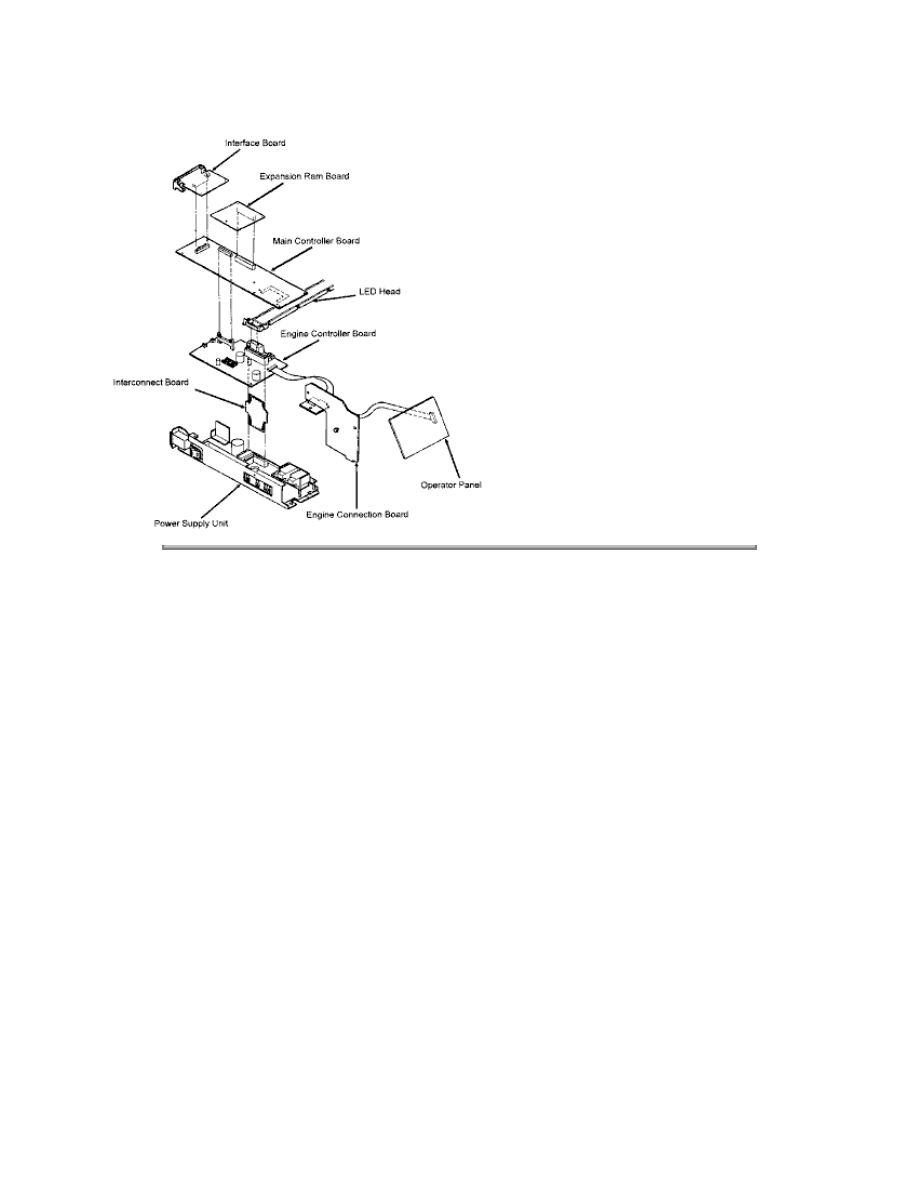
Copyright 1997, Okidata, Division of OKI America, Inc. All rights reserved. See the OKIDATA Business
Partner Exchange (BPX) for any updates to this material. (http://bpx.okidata.com)

Page: 93
Service Guide OL400
Chapter A Reference Charts
A.2.01 Main Controller Board (LBPE / LBPF)
Firmware
O4B - PROM (512K) - Program
O5B - PROM (512K) - Program
07C-Masked ROM (4Mbit) - Resident Fonts
Fuses
NONE
Jumpers
NONE
Sensors
NONE
Switches
NONE
Test Points
+5vdc CN1-1
+12vdc CN1-8
-12vdc CN1-9
Ground - CN1-3
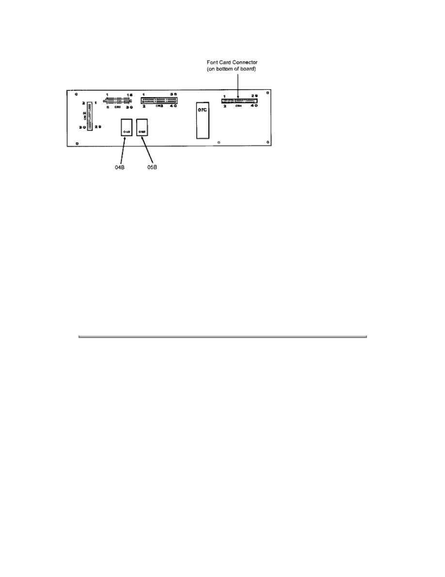
NOTES:
OL400 Revision B has been cut-in beginning with Serial #005B0010155. It includes the
hardware listed below.
Main Controller Board LBPF (P/N 55053501)
Program ROMs 02B (P/N 31072201), 03B (P/N 31072301) Self-Test 3.10
Parallel I/F L LCQ P/N 55053601
Paper Delivery Unit P/N 50213801
The program ROMs for the LBPF and LBPE are not compatible.The LBPE and LBPF PCBs may
be used in either Revision A or revision B, provided the proper program ROMs are used.The
parallel interface boards and the Paper Deliver Units are interchangeable between both A and B
revisions of the OL400.Revision A Program ROMs are 04B (PN31060501), 05B (PN31060601),
Self-Test 2.22.
Copyright 1997, Okidata, Division of OKI America, Inc. All rights reserved. See the OKIDATA Business
Partner Exchange (BPX) for any updates to this material. (http://bpx.okidata.com)

Page: 94
Service Guide OL400
Chapter A Reference Charts
A.2.02 Engine Controller Board (LLAB)
Firmware
Q1 - EPROM (64Kbyte) - Engine Control
Beginning with LLAB Revision 11, Q1 is not needed. The Q1 ROM has been changed to
a
Masked ROM internal to MPU 83C154, which replaces MPU 80C51.
IC2 - EEPROM (1,024 bit)
Fuses
NONE
Jumpers
NONE
Sensors
Resist Sensor
Outlet Sensor
Toner End Sensor (not used at this time )
Switches
NONE
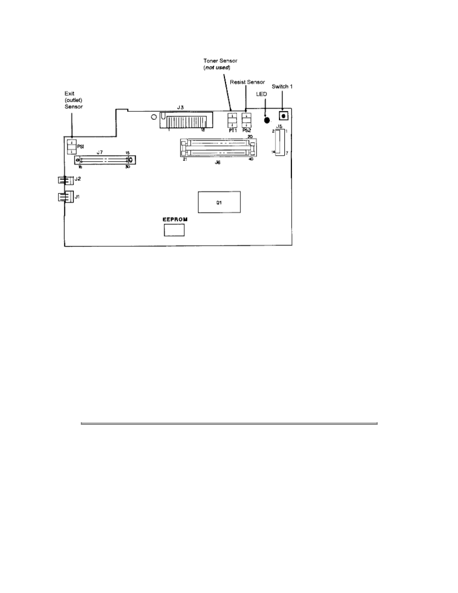
Test Points
+38vdc J1 pin 1 (Fan driving power supply)
+5vdc J3 pins 12, 2 (Power source of LED Head Assembly)
+5vdc J9 pin 7 (Power supply)
+5vdc J5 pin 5 (Power Supply)
+38vdc J5 pin 13 (Resist motor drive voltage)
+38vdc J6 pin 15 (Power Supply)
+5vdc J6 pins 13,31,32 (Power Supply)
Ground - J6 pin 16
Copyright 1997, Okidata, Division of OKI America, Inc. All rights reserved. See the OKIDATA Business
Partner Exchange (BPX) for any updates to this material. (http://bpx.okidata.com)
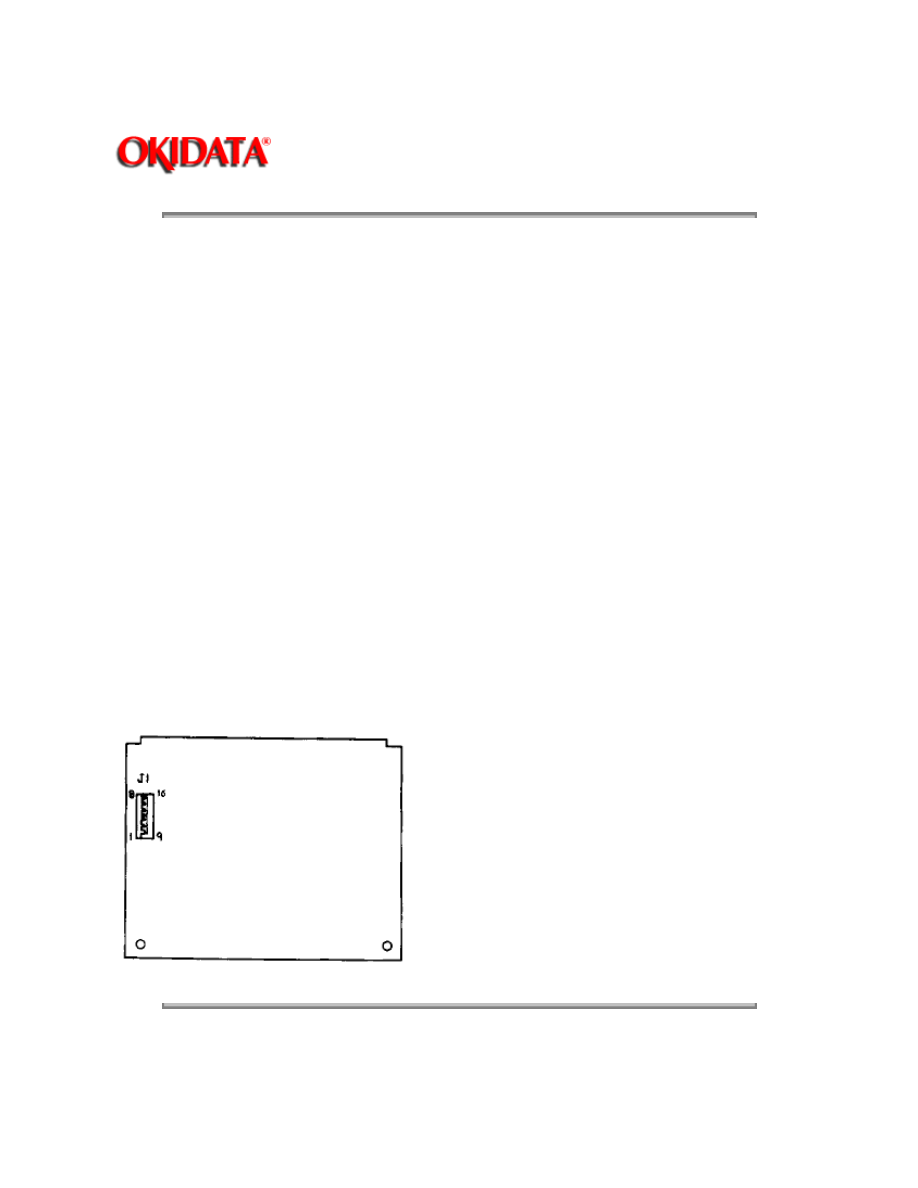
Page: 95
Service Guide OL400
Chapter A Reference Charts
A.2.03 Operator Panel PCB (LLDC)
Firmware
NONE
Fuses
NONE
Jumpers
NONE
Sensors
NONE
Switches
NONE
Test Points
NONE
Copyright 1997, Okidata, Division of OKI America, Inc. All rights reserved. See the OKIDATA Business
Partner Exchange (BPX) for any updates to this material. (http://bpx.okidata.com)
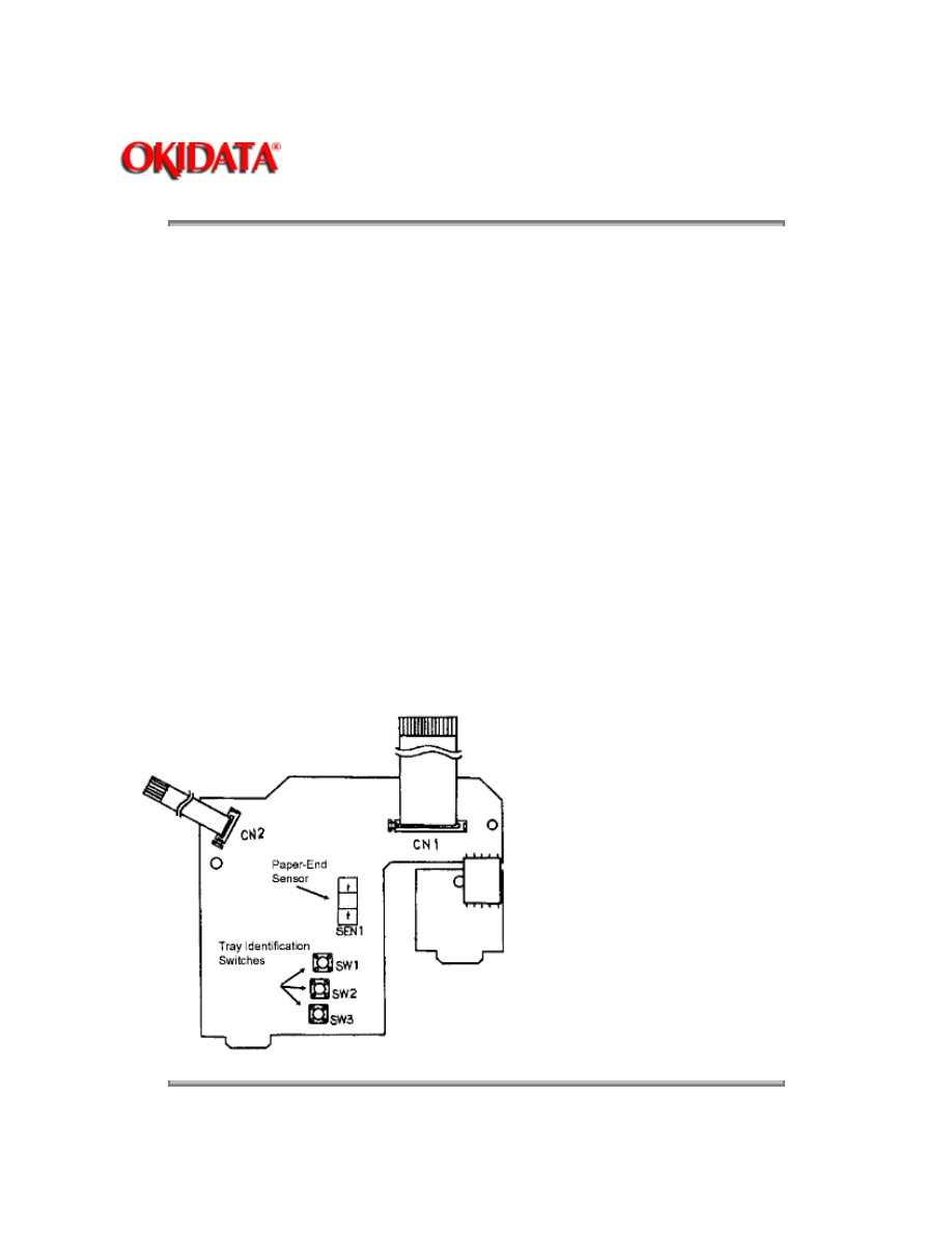
Page: 96
Service Guide OL400
Chapter A Reference Charts
A.2.04 Engine Connection PCB (LLCC)
Firmware
NONE
Fuses
NONE
Jumpers
NONE
Sensors
Paper-End Sensor
Switches
Paper Tray identification switches
Test Points
NONE
Copyright 1997, Okidata, Division of OKI America, Inc. All rights reserved. See the OKIDATA Business

Partner Exchange (BPX) for any updates to this material. (http://bpx.okidata.com)

Page: 97
Service Guide OL400
Chapter A Reference Charts
A.2.05 Centronics Parallel Interface PCB (LLCP / LLCQ)
Firmware
NONE
Fuses
NONE
Jumpers
NONE
Sensors
NONE
Switches
S1- Installed : +5vdc on CN5 Pin 18
Test Points
NONE
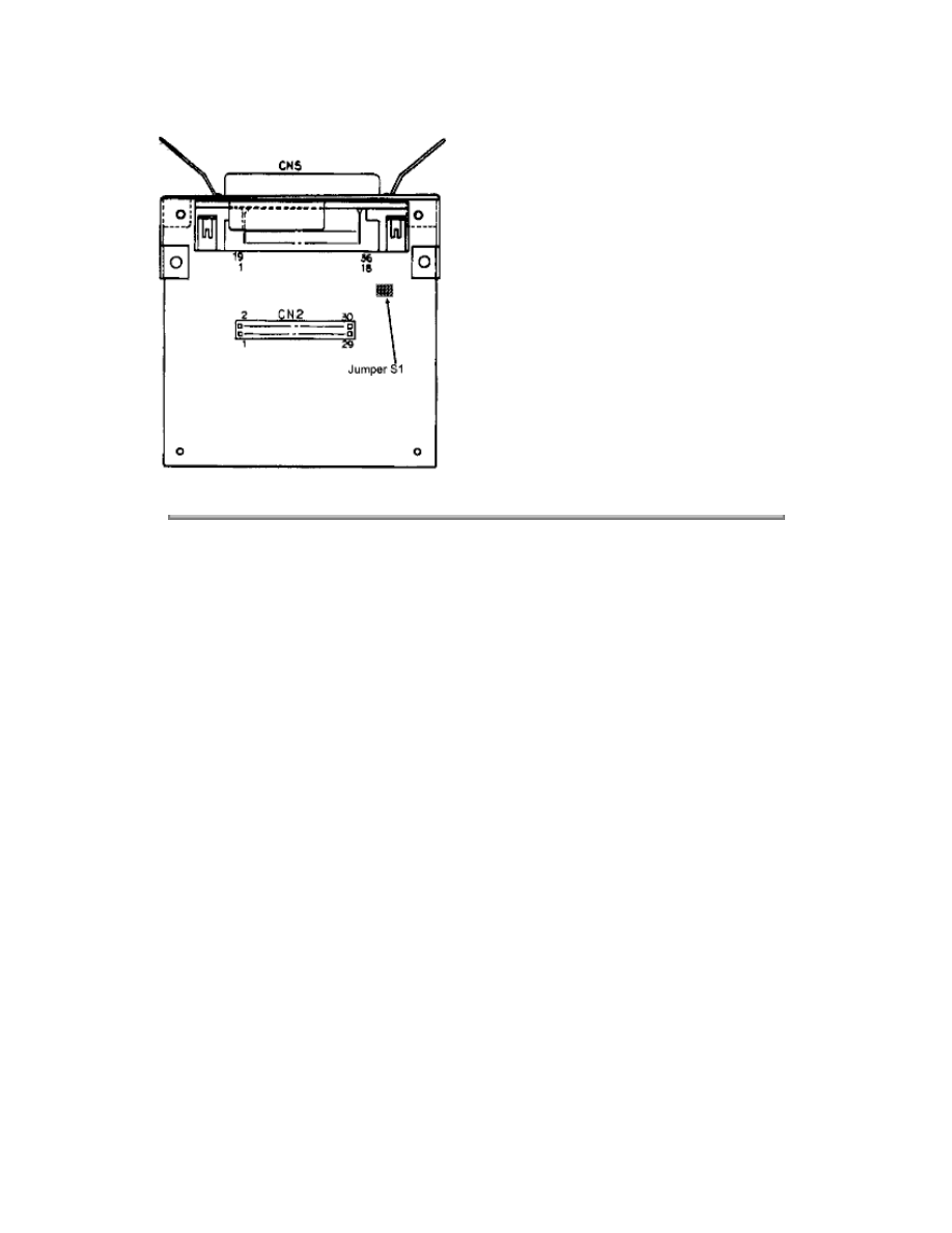
Copyright 1997, Okidata, Division of OKI America, Inc. All rights reserved. See the OKIDATA Business
Partner Exchange (BPX) for any updates to this material. (http://bpx.okidata.com)
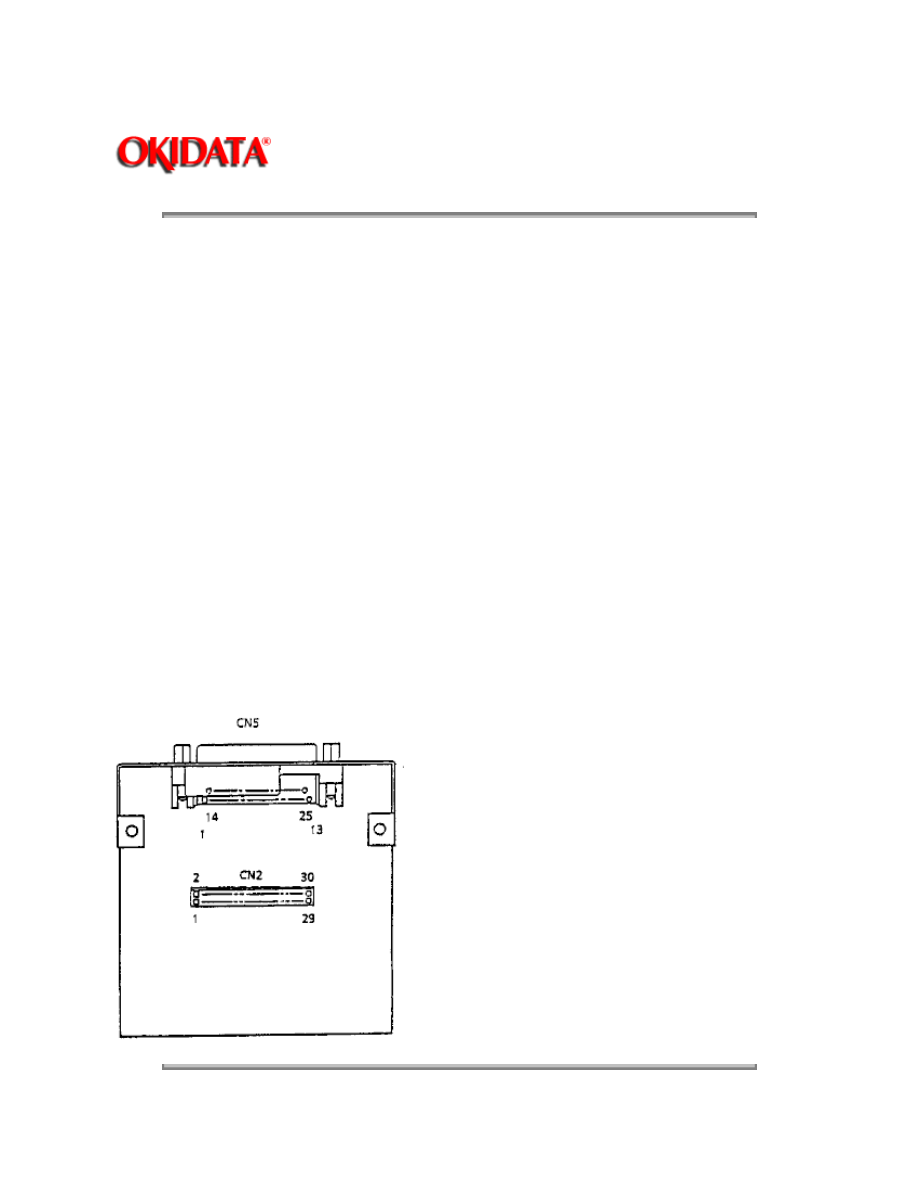
Page: 98
Service Guide OL400
Chapter A Reference Charts
A.2.06 RS-232C Interface PCB (LLRS)
Firmware
NONE
Fuses
NONE
Jumpers
NONE
Sensors
NONE
Switches
NONE
Test Points
NONE

Copyright 1997, Okidata, Division of OKI America, Inc. All rights reserved. See the OKIDATA Business
Partner Exchange (BPX) for any updates to this material. (http://bpx.okidata.com)
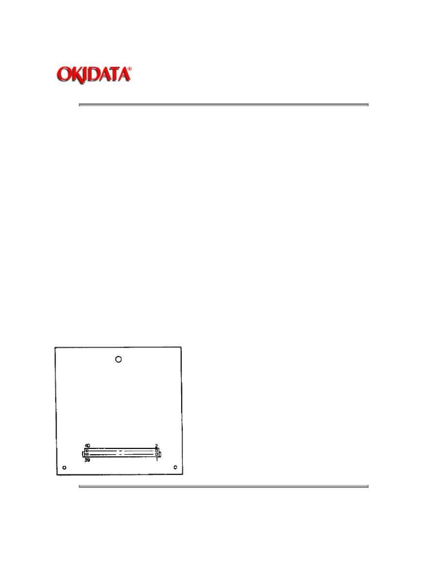
Page: 99
Service Guide OL400
Chapter A Reference Charts
A.2.07 Expansion RAM Board (optional) (RAMK / RAMH)
Firmware
NONE
Fuses
NONE
Jumpers
NONE
Sensors
NONE
Switches
NONE
Test Points
NONE
Copyright 1997, Okidata, Division of OKI America, Inc. All rights reserved. See the OKIDATA Business
Partner Exchange (BPX) for any updates to this material. (http://bpx.okidata.com)

Page: 100
Service Guide OL400
Chapter A Reference Charts
A.2.08 Power Interconnect Board (LLIE)
Firmware
NONE
Fuses
NONE
Jumpers
NONE
Sensors
NONE
Jumpers
NONE
Testpoints
NONE
Copyright 1997, Okidata, Division of OKI America, Inc. All rights reserved. See the OKIDATA Business
Partner Exchange (BPX) for any updates to this material. (http://bpx.okidata.com)

Page: 101
Service Guide OL400
Chapter A Reference Charts
A.2.09 Power Supply Unit
Fuses
F1: AC Line Fuse (125V 8A)
F2: +38 V Line Fuse (125V 2.5A)
Firmware
NONE
Jumpers
NONE
Sensors
NONE
Switches
Cover Interlock Switch
Testpoints:
+5V CN1 pins 13,31,32
+12V CN1 pin 12
-12V CN1 pin 11
+38V CN1 pin 15
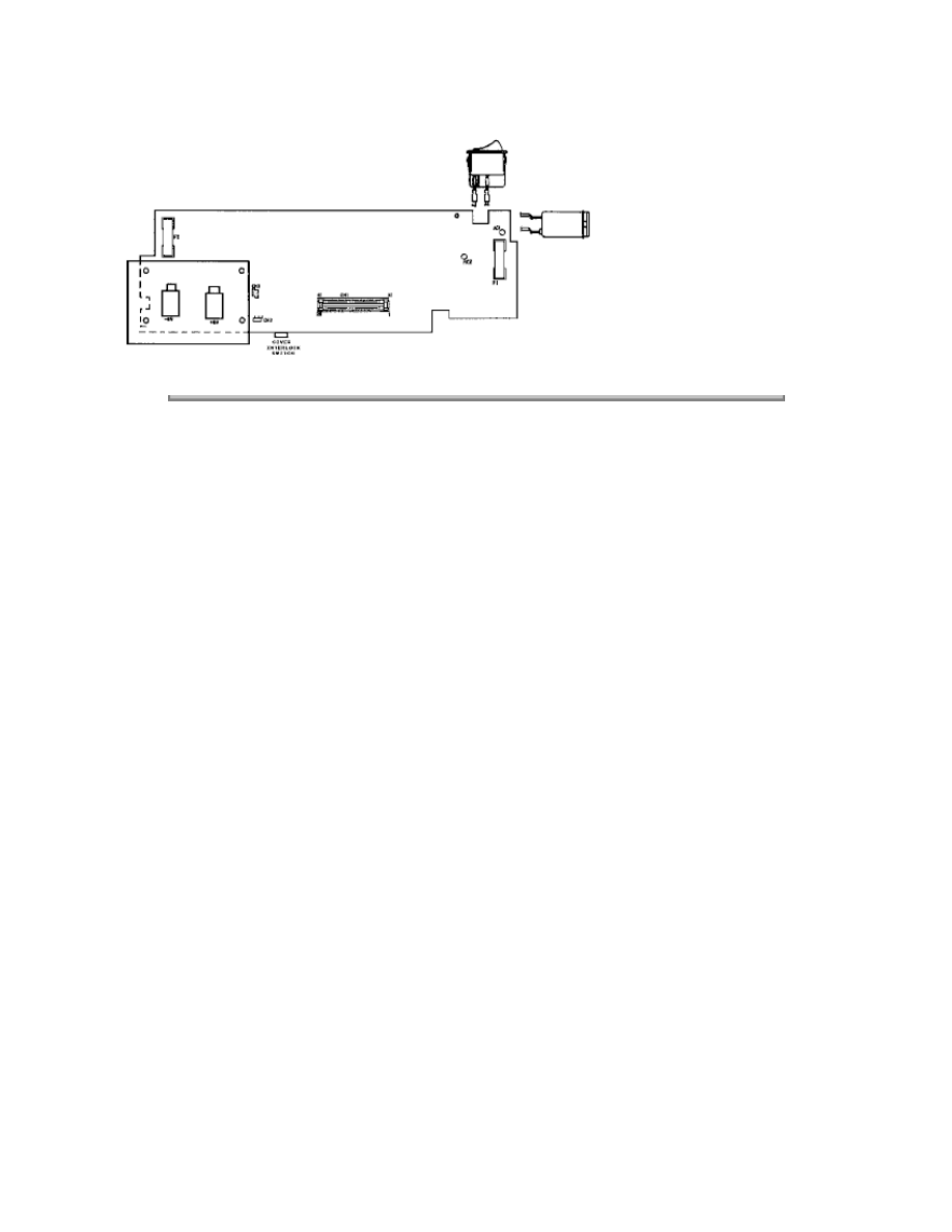
Copyright 1997, Okidata, Division of OKI America, Inc. All rights reserved. See the OKIDATA Business
Partner Exchange (BPX) for any updates to this material. (http://bpx.okidata.com)

Page: 102
Service Guide OL400
Chapter B Illustrated Parts Listing
B.1
ILLUSTRATED PARTS LISTING
B.1.01 General Information
This appendix will assist you in identifying the assemblies and parts of the printers. Once you
have used Section Four (Failure Analysis) to find a defective part, you can locate the part number
in this section.
The format for this appendix is a series of tables with diagrams. The table contains the item
reference number, the part description, and the Okidata part number. Also note that some items
are only available as assemblies. Every effort has been made to clearly indicate which items are
in assemblies and which are not.
Please read the Definition of Terms in the following section carefully. It is important that you
understand the different types of parts classifications and their availability.
Please refer to the following resources for current part numbers and pricing.
Okidata's Bulletin Board (Okilink II) contains current part numbers, prices, and recommended
stocking levels for each item listed as a recommended spare part. For instructions on accessing
Okilink II, refer to the Service Center Reference Guide.
Okidata's Faxable Facts is an automated fax document retrieval system. Part numbers and pricing
are available through Faxable Facts. For instructions on accessing Faxable Facts, refer to the
Service Center Reference Guide.
Okidata's Technical Information Group is a telephone support line reserved for Authorized
Dealers. Part numbers and pricing are available through Technical Information. For instructions on
accessing Technical Information, refer to the Service Center Reference Guide.
REMEMBER
Current part numbers, recommended stocking levels, and pricing information are available
through Okilink II, Faxable Facts, and Technical Information. Refer to the Service Center
Reference Guide for information on accessing these resources.
Copyright 1997, Okidata, Division of OKI America, Inc. All rights reserved. See the OKIDATA Business
Partner Exchange (BPX) for any updates to this material. (http://bpx.okidata.com)

Page: 103
Service Guide OL400
Chapter B Illustrated Parts Listing
B.1.02 Definitions of Terms
RSPL
Okidata recommends that this part/assembly be on hand for servicing.
Consumable
A consumable is a supply item which has a specified life and needs to be replaced periodically. It
is purchased and installed by the end user. Okidata machines are designed to work exclusively
with Okidata consumables. By using genuine Okidata consumable products, the investment made
in the equipment will be protected.
Option
An option is a part/assembly which is added to a product and expands the product's functionality.
An option may or may not be installed by the end-user. Instructions for installation accompany
each option.
Option RSPL
Okidata recommends that this part/assembly be on hand for servicing installed options.
Document
A document is a printed item which supports the service and marketing of a product. Various
documents are available from Okidata.
Blank
Okidata does not recommend stocking this item. This item should be purchased on an As
Required Basis only. The availability of this item is NOT guaranteed by Okidata.
Copyright 1997, Okidata, Division of OKI America, Inc. All rights reserved. See the OKIDATA Business
Partner Exchange (BPX) for any updates to this material. (http://bpx.okidata.com)

Page: 104
Service Guide OL400
Chapter B Illustrated Parts Listing
B.1.03 Parts Ordering Information
General Information
All authorized Okidata Dealers may order spare parts and consumables for Okidata products.
Orders are placed through Okidata's Logistics Department.
When a technician has successfully completed a product certification course and the Dealer has
become service authorized, an information package will be provided to the Dealer. The Okidata
Service Center Reference Guide outlines the following.
Responsibilities of Okidata Service Centers
Spare parts and consumables information
Procedures for warranty repairs
Product training, certification, and authorization
Product support information
Okidata depot information and services
Third party service information
Information about Okidata's Customer Information Center
Okidata service and support telephone numbers.
The Service Center Reference Guide contains detailed procedures to follow when ordering parts.
Please read, understand, and follow these procedures. Service authorization for a specific product
must be obtained before a Dealer can submit warranty claims.
Questions regarding the Service Center Reference Guide should be directed to Okidata Dealer
Service.
Placing a Parts Order
Please refer to the Service Center Reference Guide for details on ordering parts.
The following information MUST be available before an order is placed.
Okidata Dealer Authorization Number
Purchase Order number
Serial Number / Revision Level of the printer(s)
Okidata Part Number(s)
Use this Appendix, Okilink II, Faxable Facts, or Technical Information to find the correct part
number. Refer to the Service Center Reference Guide for information on contacting Okidata.

Copyright 1997, Okidata, Division of OKI America, Inc. All rights reserved. See the OKIDATA Business
Partner Exchange (BPX) for any updates to this material. (http://bpx.okidata.com)
Page: 105
Service Guide OL400
Chapter B Illustrated Parts Listing
B.2
CHARTS
Below is an index to the illustrated parts breakdown charts.
Index to Charts
Description
Section
Items 1 - 7
B.2.01{
}
Items 8 - 16
B.2.02{
}
Items 17 - 27, and 41
B.2.03{
}
Items 28 - 35
B.2.04{
}
Items 36 - 40
B.2.05{
}
Copyright 1997, Okidata, Division of OKI America, Inc. All rights reserved. See the OKIDATA Business
Partner Exchange (BPX) for any updates to this material. (http://bpx.okidata.com)
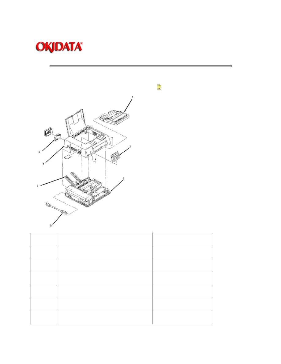
Page: 106
Service Guide OL400
Chapter B Illustrated Parts Listing
B.2.01 Items 1 - 7
Part numbers are subject to change.
Refer to Section B.1.01{
}
for finding current information.
Item
Part Description
Okidata Part Number
1
Paper Cassette (Letter Size)
70013601
1
Paper Cassette (Legal Size)
70013701
2
Operator Panel Assembly
50213501
3
Lower Unit (Printer Base)
50213601
4
Upper Cover
50213901
5
AC Power Cord
56609701

6
Ozone Filter
55503501
7
Face-up Stacker Assembly
50066601
Copyright 1997, Okidata, Division of OKI America, Inc. All rights reserved. See the OKIDATA Business
Partner Exchange (BPX) for any updates to this material. (http://bpx.okidata.com)
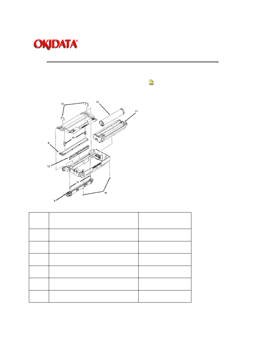
Page: 107
Service Guide OL400
Chapter B Illustrated Parts Listing
B.2.02 Items 8 - 16
Part numbers are subject to change.
Refer to Section B.1.01 {
}
for finding current information.
Item
Part Description
Okidata Part
Number
8
LED Head
55619501
9
Fusing Unit (120 volts)
55044901
9
Fusing Unit (240 volts)
55044902
10
Toner Cartridge
52104201
11
Image Drum Cartridge
56106601
12
Fuser Cleaning Pad
53500901

13
LED Head Clamp Spring
50914301
14
LED Head Bias Spring
50914101
15
Fusing Unit Spring
50914601
16
Image Drum Tray Spring
50917205
**
120vac Upper Unit (includes #8 9
12 13 14 15 & 16)
50213701
**
240vac Upper Unit (includes #8 9
12 13 14 15 & 16)
50213702
Copyright 1997, Okidata, Division of OKI America, Inc. All rights reserved. See the OKIDATA Business
Partner Exchange (BPX) for any updates to this material. (http://bpx.okidata.com)
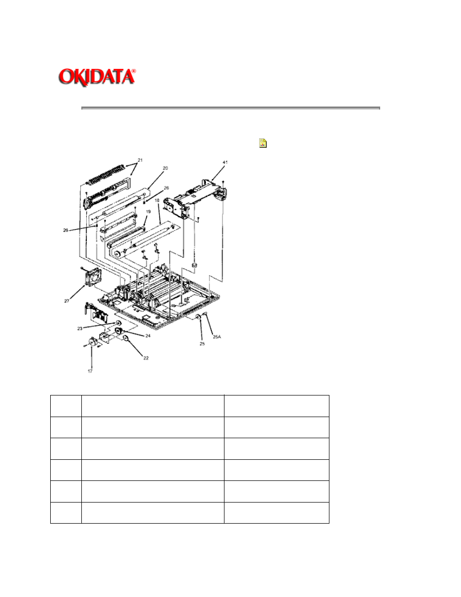
Page: 108
Service Guide OL400
Chapter B Illustrated Parts Listing
B.2.03 Items 17 - 27, and 41
Part numbers are subject to change.
Refer to Section B.1.01 {
}
for finding current information.
Item
Part Description
Okidata Part Number
17
Main Pulse Motor
56507301
18
Resist Roller Assembly
50079101
19
Transfer Charger Assembly
50087301
20
Backup Roller Assembly
50079001
21
Paper Exit Assembly
50066501

22
Idle Gear "A"
51218401
23
Idle Gear "B"
51218501
24
Reduction Gear
51218701
25
Idle Gear (in base)
51218601
25A
Post
53329501
26
Backup Roller Pressure Spring
50914801
27
DC Fan Assembly
56507601
Copyright 1997, Okidata, Division of OKI America, Inc. All rights reserved. See the OKIDATA Business
Partner Exchange (BPX) for any updates to this material. (http://bpx.okidata.com)
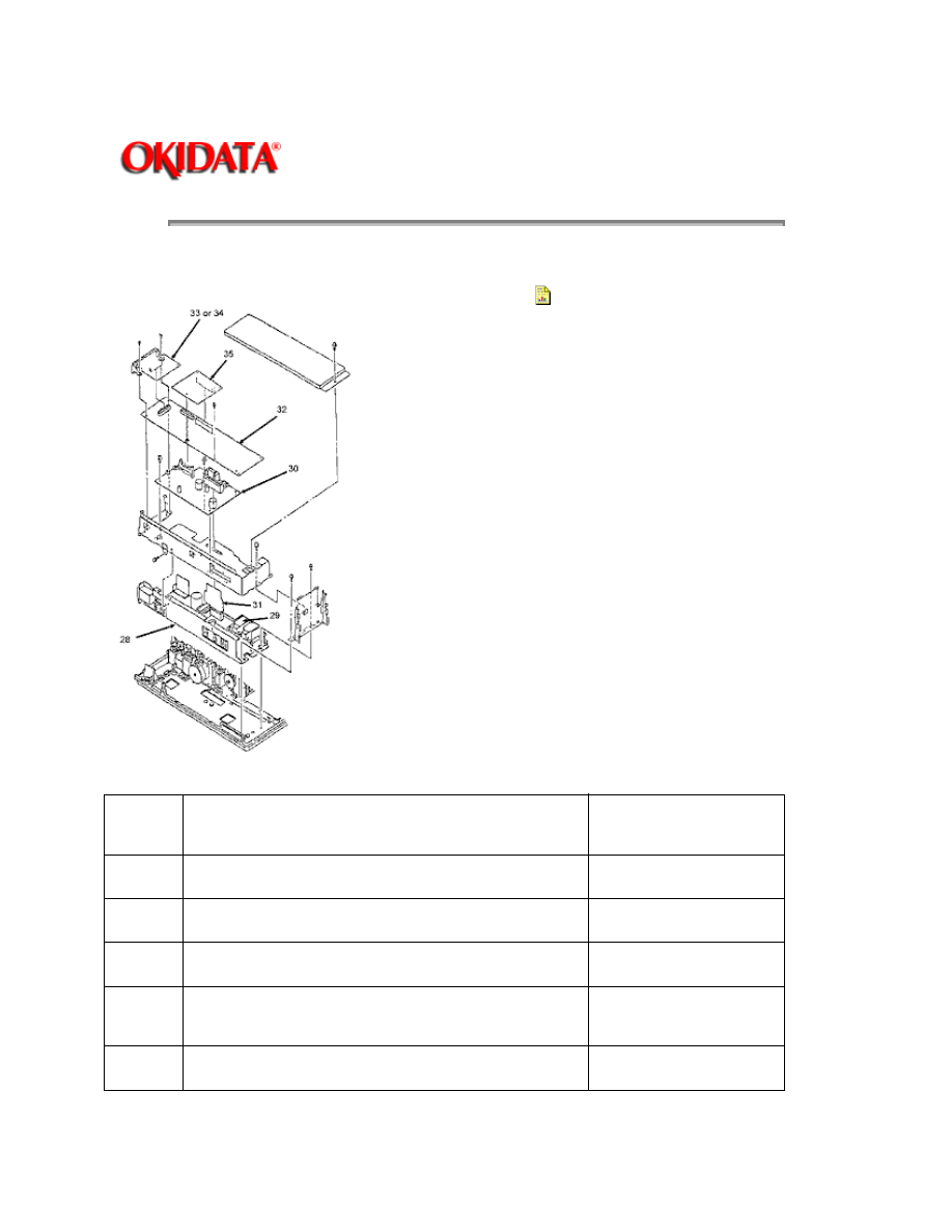
Page: 109
Service Guide OL400
Chapter B Illustrated Parts Listing
B.2.04 Items 28 - 35
Part numbers are subject to change.
Refer to Section B.1.01 {
}
for finding current information.
Item
Part Description
Okidata Part
Number
28
Power Supply Unit (120Volts)
56408703
28
Power Supply Unit (240Volts)
56408702
29
High Voltage Power Unit
55047301
30
Engine Controller Board (LLAB PCB)
without ROM
55044401
31
Power Connection Board (LLIE PCB)
55044701

32 *
Main Controller Board (LBPE PCB) w/o ROM
55045901
32 *
Main Controller Board (LBPK PCB) w/o ROM
55053501
32 *
Main Controller Board (LBPK PCB) w/o ROM
55062701
33
Centronics Interface Board (LLCP PCB)
55044201
33
Centronics Interface Board (LLCQ PCB)
55053601
33
Centronics Interface Board (LLCR PCB)
Not available as a
spare part
34
RS232-C Serial Interface Board (LLRS PCB)
55044301
35
RAM Expansion Board (w/ 1MB)
55040901
NOTE:
Three Main Controller Boards are available.
See Appendix A { }
for information on installing the correct board.
Copyright 1997, Okidata, Division of OKI America, Inc. All rights reserved. See the OKIDATA Business
Partner Exchange (BPX) for any updates to this material. (http://bpx.okidata.com)
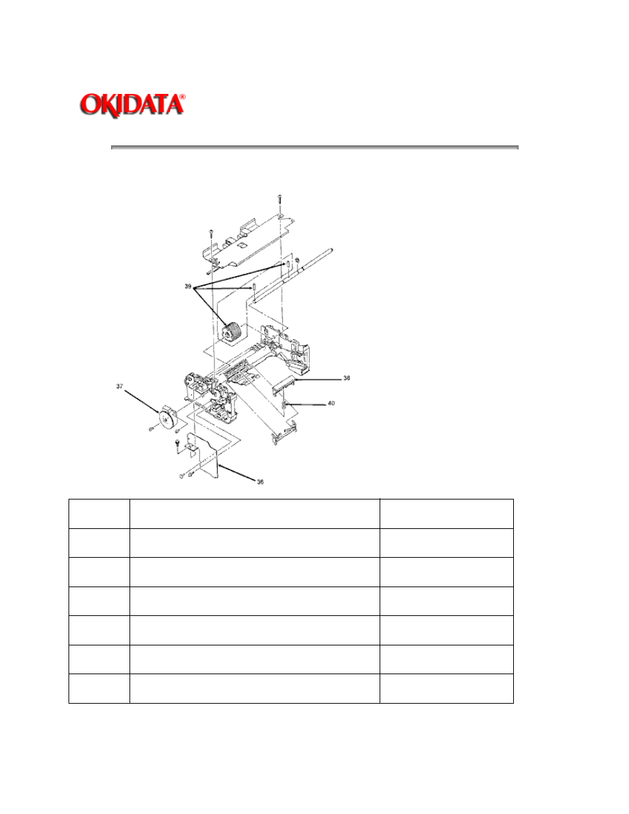
Page: 110
Service Guide OL400
Chapter B Illustrated Parts Listing
B.2.05 Items 36 - 40
Item
Part Description
Okidata Part Number
36
Engine Connection Board (LLCC PCB)
55044601
37
Resist Motor (70 Ohms)
56507401
37A
Resist Motor (79 Ohms)
56507402
38
Separator
53500501
39
Hopping Roller (includes 2 pins)
53500601
40
Separator Spring
50917101

41
Paper Feed Assembly<R>Includes all
items shown on drawing
50213801
Not
Shown
Paper Cassette Spring
50917001
Not
Shown
Cover Open Switch<R>(mounted on the
Power Supply Frame)
55050701
Part numbers are subject to change.
Refer to Section B.1.01 { }
for finding current information.
Copyright 1997, Okidata, Division of OKI America, Inc. All rights reserved. See the OKIDATA Business
Partner Exchange (BPX) for any updates to this material. (http://bpx.okidata.com)
Wyszukiwarka
Podobne podstrony:
Okidata OL 840 Service Manual
Brother MFC 830, 840 Parts Manual
LECTURE 4 Anglo Saxons 400 800 AD
Tips and Tricks for Atari 400 800
Trommel 820 830 Part 3
OKI jet 2500 service manual
XC 400 SERVICE MANUAL
hplj 5p 6p service manual vhnlwmi5rxab6ao6bivsrdhllvztpnnomgxi2ma vhnlwmi5rxab6ao6bivsrdhllvztpnnomg
Oberheim Prommer Service Manual
Korg SQ 10 Service Manual
MAC1500 service manual
Kyocera Universal Feeder UF 1 Service Manual
Proview RA783 LCD Service Manual
więcej podobnych podstron