High-pressure Connections
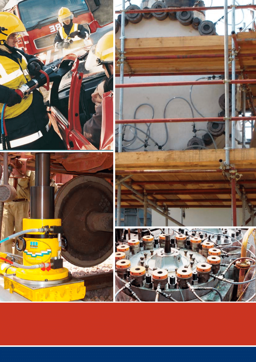
Quick Connect Products for High-pressure
Hydraulik Applications
high-pressure
h
ydraulics
2
ceJN reserves the right to make changes without further notification.
3
04
ceJN – a partNer to couNt oN with
high pressure
06
coNsideratioNs with high pressures
08
Flat-Face coupliNgs
10
product raNge
17
complemeNtary products
23
Facts aNd Figures
25
applicatioN guide
Content
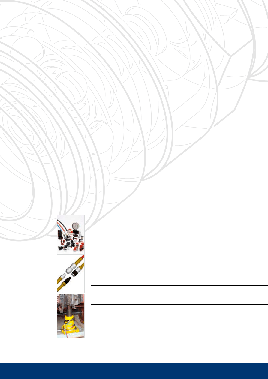
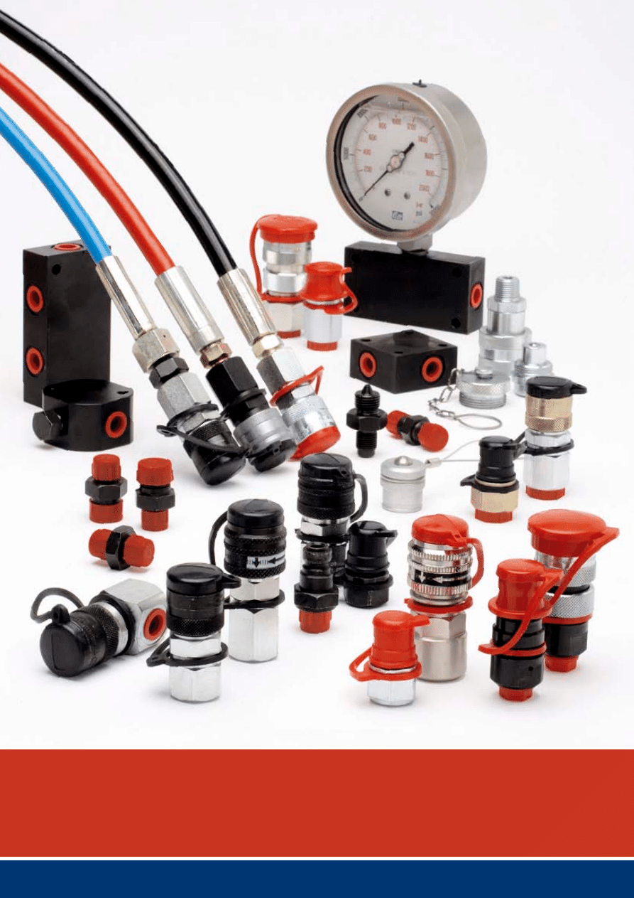
For ultra-high pressure hydraulics, ceJN provides
industry with the most complete line of high performance
quick couplings.
4
Low overall cost
CEJN’s ultra-high pressure hydraulics range gives you a wide choice of quick connect couplings with cost
saving features, such as non-drip valves, dust caps, true “quick-connect” action; plus components made
of hardened steel for dependable and repeated cycling, leading to long service life and lower maintenance
costs.

5
CEJN is the world leader in quick connect coupling technology for high
pressure hydraulics. With more than 50 years of experience in the indus-
try, we have demonstrated our ability to provide solutions for the most
demanding applications.
years of research and development have led to our vast product offering and leading position in non-
drip quick couplings technology. Maximum flexibility, safety and reliability are the cornerstones that
determine functional design and material selection. the result is a complete range of quick connect
couplings especially designed for ultra-high pressure pumps, jacks, clamps, rescue equipment, torque
and tensioning tools, diagnostics and other demanding applications.
Quick coNNect Features
although other manufactures may offer couplings under the heading of “quick connect,” the ultra-high
product range from ceJN is one of the few lines that include a truly quick to connect design; without
threads that may bind or only partially connect. The safe, automatic locking system facilitates faster
access, particularly suitable for confined areas.
uNiQue advaNtages!
Designed with a non-drip interface, CEJN’s series of ultra-high pressure couplings minimize both fluid
spillage and air inclusion, saving clean-up costs and our environment, as well as ensuring proper
system function.
In order to minimize unexpected downtime and increase reliability, all exposed components are manu-
factured with hardened steel to provide longer service life in rugged environments. another advantage
of the ceJN ultra-high series is the small envelope size, allowing easy installation and quick access to
your fluid lines in confined spaces.
dust caps are staNdard
All CEJN couplings are fitted with dust caps as standard. Because dirt and debris have known adverse
affects on hydraulic systems, dust caps should always be used whenever the two halves are separated.
Additionally, the two dust cap halves should be connected together whenever the coupling halves are
connected; thereby preventing contamination from entering the dust caps. As standard practice, both
the coupling and nipple halves should be thoroughly inspected and wiped clean prior to every connec-
tion.
high workiNg pressure
with operating pressures as high as 300 mpa, the ceJN product range includes several couplings with
a flat-face design, for ease of cleanliness. All coupling halves are designed to withstand the full work-
ing pressure while disconnected; however the nipples generally have a lower rated pressure when in
the disconnect position.
CEJN’s ultra-high pressure product range also includes accessories, such as hose assemblies, adapt-
ers, pressure gages and porting blocks.
Quality
Before leaving CEJN’s production facility, every coupling is tested multiple times to ensure functional-
ity and performance. Each part is checked before, during and after assembly. Prior to shipment, each
coupling is also function and leak tested to ensure that you receive a reliable, proven product.
other products From ceJN
ceJN’s line of hydraulic products also includes quick connect couplings for low and intermediate pres-
sure applications, as well as multi-couplings and auto-couplings. contact ceJN for additional informa-
tion and product bulletins.
CEJN – a partner to count
on with high pressure
CEJN Corporate Headquarter
CEJN AB
skövde, sweden
CEJN Sales Offices:
CEJN Norden AB
skövde, sweden
ceJN denmark aps
Esbjerg, Denmark
CEJN Product GmbH
troisdorf, germany
ceJN France s.a.s
paris, France
ceJN ag
cham, switzerland
ceJN italy s.r.l.
milan, italy
CEJN Ibérica S.L.
Barcelona, Spain
ceJN industrial corporation
chicago, usa
CEJN Do Brasil LTDA
Curitiba, Brazil
ceJN australia pty limited
sydney, australia
ceJN japan corporation
tokyo, Japan
ceJN products Far east pte ltd.
singapore city, singapore
ceJN products Far east co, ltd.
seoul, korea
ceJN shanghai Fluid systems co ltd
shanghai, china
ceJN products india pvt. ltd.
Bangalore, India
ISO 9001 certified since 1995.
ISO 14001 certified since 2006.
6

7
sealiNg at ultra-high pressures
ceJN recommends the use of metal-to-metal cone seats for ultra-high pressure hydraulic couplings.
For pressures of 70 MPa and above, we have developed a unique seal that incorporates a 120°
cone. The 120° cone allows for the seal to take place on a relatively small diameter, which minimizes
strain on the threads. Additionally, the threads are straight, not tapered, thereby eliminating the risk of
cracked threads under over-torque conditions. Because the CEJN connection has very good sealing
properties at low tightening torque, the joint can be reassembled many times without damaging the
sealing surfaces.
when using tapered threads, such as Npt or r, we recommend the use of a liquid or paste sealant
- not thread tape (i.e. PTFE based tape), which may serve more as a lubricant and lead to cracked
components. Thread tape may also become dislodged and find its way into hydraulic components,
thereby causing damage or system malfunction.
Rubber-metal seals can be used when sealing parallel threads against boss or components with the
appropriate sealing face. Rubber-metal seals should be avoided at pressures above 100 MPa.
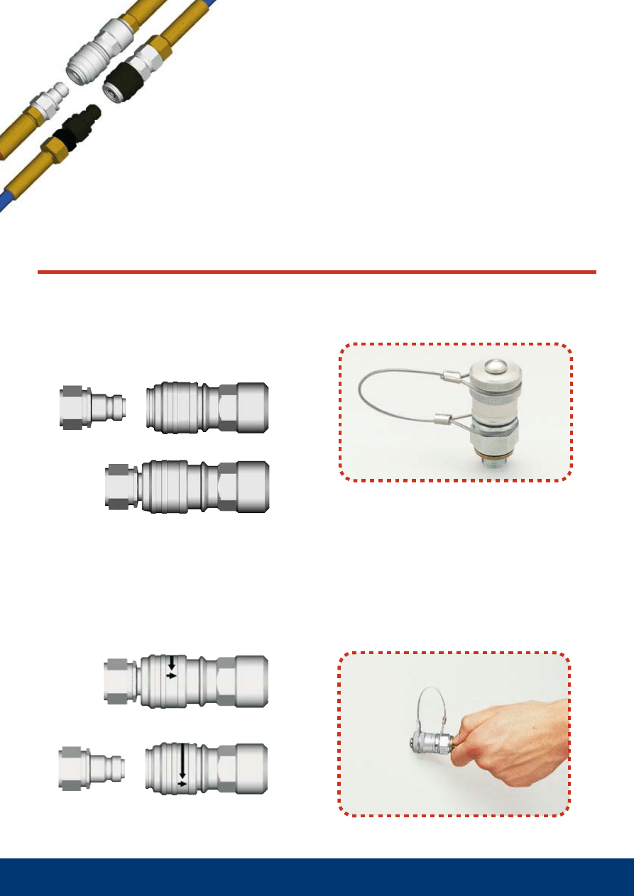
coNNectiNg the two halves
when connecting the two halves, always make sure that the locking sleeve moves forward to ensure a
positive lock. Ultra-high pressure series couplings are not designed to be connected under pressure,
as seal damage may occur.
dust caps
Extend product life by using dust caps. Dust or dirt on the coupling/nipple can easily enter the hydrau-
lic system and in doing so impair the oil quality and system performance and in the worse possible
scenario result in production downtime.
CEJN’s dust caps can, as an extra safety precaution, be connected together to prevent dust from
becoming attached to them when the nipple and coupling are connected.
Despite these precautions, you should still wipe off the coupling and nipple before connection.
Considerations with
high pressures
1 bar = 0.1 MPa
1 bar = 0.987 atm
1 bar = 14.5 PSI
1 bar = 1.02 kg/cm2
1 MPa = 10 bar
1 MPa = 9.87 atm
1 MPa = 145 PSI
1 MPa = 10.2 kg/cm2
1 atm = 0.101 MPa
1 atm = 1.013 bar
1 atm = 14.7 PSI
1 atm = 1.03 kg/cm2
1 PSI = 0.007 MPa
1 PSI = 0.068 atm
1 PSI = 0.067 bar
1 PSI = 0.07 kg/cm2
1 kg/cm
2
= 0.098 MPa
1 kg/cm
2
= 0.968 atm
1 kg/cm
2
= 98 067 PSI
1 kg/cm
2
= 0.980 bar
8
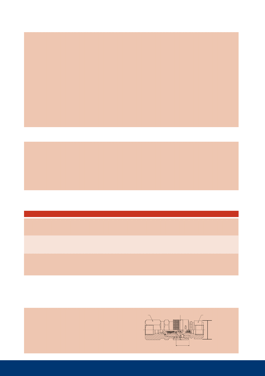
The one-hand-to-connect Flat-Face couplings have been
developed to reliably meet the rigorous demands of ultra-
high pressure hydraulic applications. Engineered to exacting
tolerances, using the most durable materials, CEJN ultra-high
pressure couplings hold up where other couplings fail.
Flat-Face
A one-hand-to-connect, non-drip
coupling with built-in safety function
One-hand-to-connect
The nipple is pushed into the coupling and is locked automati-
cally. The locking sleeve does not need to be manually posi-
tioned.
Unique automatic safety function
eliminates accidental disconnection
Turn the locking sleeve 30° and then pull backwards to release.
The Flat-Face design ensures non-drip disconnection
Residual line pressure on the nipple side can some-
times make it difficult to connect the coupling, result-
ing in unnecessary downtime and frustration. By
depressing the button on our new pressure eliminating
dust cap, internal pressure is relieved, allowing the two
halves to easily connect.
Unique dust cap for nipples,
with integrated pressure eliminator
10 115 1200
G 1/4”
70.1
30.0
24
17.3
170
70-80
T
10 116 1219
G 1/4”
72.1
30.0
24
17.3
215
40-50
CMS
10 116 1229
G 3/8”
72.6
30.0
24
17.3
225
70-80
T
10 116 1419
NPT 1/4”
69.1
30.0
24
17.3
225
50-60
-
10 116 1429
NPT 3/8”
70.6
30.0
24
17.3
220
70-80
-
10 116 1269
G 1/4”
70.6
30.0
24
17.3
205
50-60
T (1*)
10 116 1279
G 3/8”
70.6
30.0
24
17.3
210
70-80
T
10 116 1469
NPT 1/4”
70.6
30.0
24
17.3
200
50-60
-
10 116 1479
NPT 3/8”
70.6
30.0
24
17.3
210
70-80
-
9
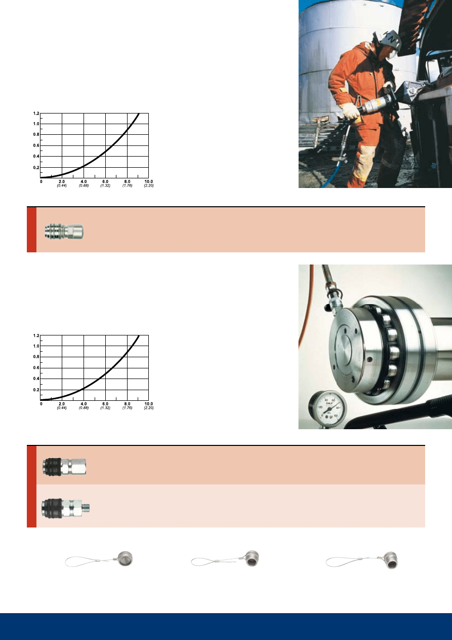
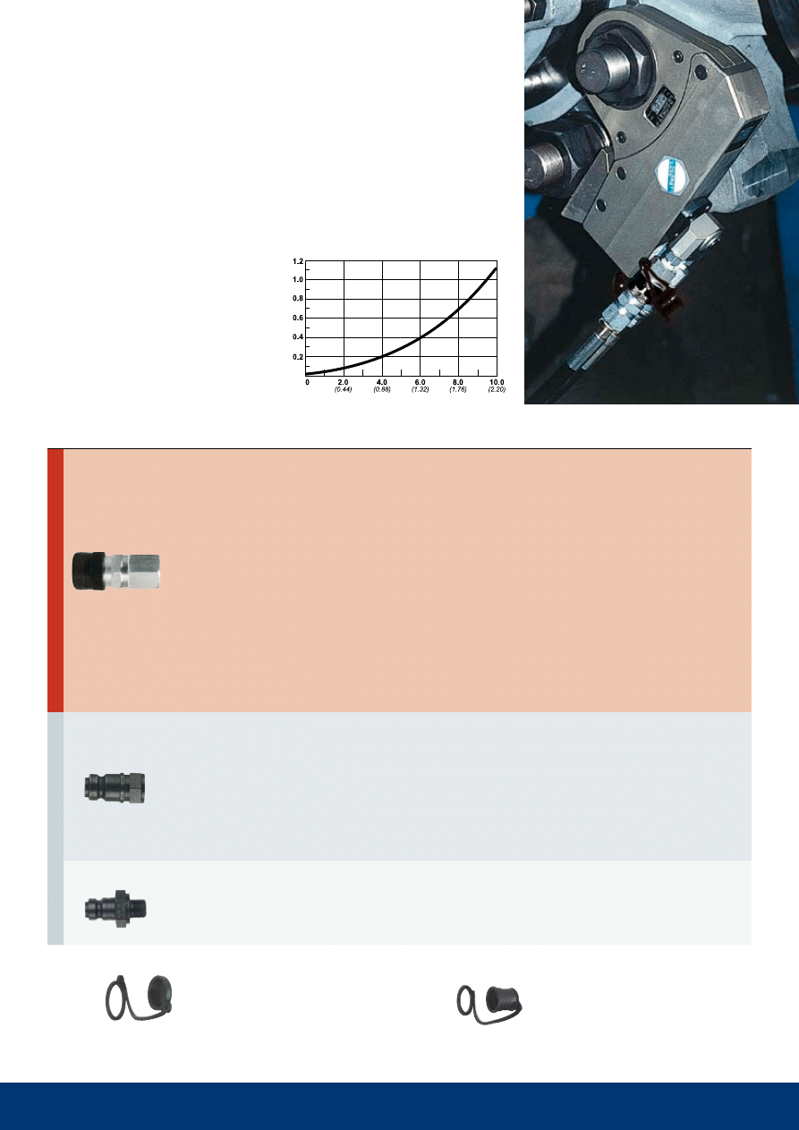
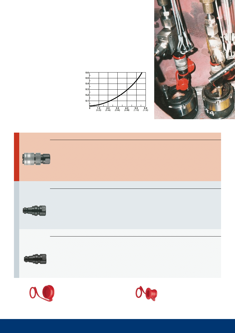
Series 115 in a Flat-Face design has a working pressure of 80 MPa. The series has a light-
weight design with an aluminum back-part, which makes the series well adapted for applica-
tions where weight has a significance. Series 115 Flat-Face is primarily recommended for
rescue equipment, torque tools and cable cutters.
The coupling can be connected to the standard 115 series nipple.
Series 116 FF for industrial applications
Series 116 in a Flat-Face design has a working pressure of 150 MPa. Series 116 Flat-Face is pri-
marily recommended for industrial applications, such as bolt tensioners, splitters and clamping
tools.
The coupling can be connected to the standard 116 series nipple.
Technical data
Material: hardened, zinc chromate plated steel
Max. working pressure: 80 MPa
Min. bursting pressure: 280 MPa
Nominal flow diameter: 2.5 mm (3/32")
Temperature range: - 30°C - +100°C
(
-20°F - + 210°F)
Flow capacity at pressure drop 0.4 MPa:
5.3 l/min (1.16 GPM UK)
The nipple should not be loaded while
disconnected, see also page 26.
Technical data
Material: hardened, zinc chromate plated steel
Max. working pressure: 150 MPa. (3/8" –100
MPa)
Min. bursting pressure: 300 mpa
Nominal flow diameter: 2.5 mm (3/32")
Temperature range: - 30°C - +100°C
(
-20°F - + 210°F)
Flow capacity at pressure drop 0.4 MPa:
5.3 l/min (1.16 GPM UK)
The nipple should not be loaded while
disconnected, see also page 26.
pressure drop mpa
Flow l/min (GPM - UK)
Flow l/min (GPM - UK)
pressure drop mpa
Dust cap in metal for Flat-Face range
For coupling, part no. 10 115 4100
For nipple, part no. 10 115 4101
For nipple, with pressure eliminator, part no.10 115 4102
Rec.
Rec. Sealing
Part No.
Connection
Length
Diameter
Hexagon
Con. stroke
Weight (g)
torque (Nm)
method
c
o
u
p
li
N
g
s
Rec.
Rec. Sealing
Part No.
Connection
Length
Diameter
Hexagon
Con. stroke
Weight (g)
torque (Nm)
method
Female thread
Female thread
male thread
c
o
u
p
li
N
g
s
Thread connections are listed according to ISO Standards (see Page 23 for more information). All measurements are in mm (Dimension key, see page 25).
Pressure conversion table, see page 24. Check with your local retailer for availability and prices.
Series 115 FF for rescue equipment
10 115 1102
Rc 1/4”
59,3
28,0
24
18,3
170
50-60
-
10 115 1104
Rc 3/8”
60,8
28,0
24
18,3
165
70-80
-
10 115 1201
G 1/8”
53,8
28,0
24
18,3
155
40-50
T
10 115 1202
G 1/4”
61,3
28,0
24
18,3
165
40-50
CMS
10 115 1204
G 3/8”
63,3
28,0
24
18,3
170
70-80
T
10 115 1222
G 1/4”
61,3
28,0
24
18,3
170
40-50
CMS
10 115 1401
NPT 1/8”
53,8
28,0
24
18,3
155
40-50
-
10 115 1402
NPT 1/4”
58,3
28,0
24
18,3
165
50-60
-
10 115 1404
NPT 3/8”
60,3
28,0
24
18,3
165
70-80
-
10 115 1422
NPT 1/4”
58,3
28,0
24
18,3
170
50-60
-
10 115 1252
G 1/4”
61,3
28,0
24
18,3
151
40-50
T
10 115 1254
G 3/8”
60,8
28,0
24
18,3
155
70-80
T
10 115 1452
NPT 1/4”
61,8
28,0
24
18,3
150
50-60
-
10 115 1454
NPT 3/8”
62,3
28,0
24
18,3
155
70-80
-
10 115 6102
Rc 1/4"
36,7
25,4
22
-
60
30-40
-
10 115 6104
Rc 3/8”
38,0
27,7
24
-
60
40-50
-
10 115 6201
G 1/8”
33,3
19,6
17
-
40
40-50
T
10 115 6202
G 1/4”
38,0
25,4
22
-
60
40-50
CMS
10 115 6204
G 3/8”
39,5
27,7
24
-
65
70-80
T
10 115 6401
NPT 1/8”
33,3
19,6
17
-
40
30-40
-
10 115 6402
NPT 1/4”
35,7
25,4
22
-
55
30-40
-
10 115 6404
NPT 3/8”
37,0
27,7
24
-
65
40-50
-
10 115 6152
R 1/4”
62,5
25,4
22
-
110
50-60
-
10 115 6154
R 3/8”
63,0
25,4
22
-
115
70-80
-
10 115 6212
G 1/4”
50,0
25,4
22
-
80
40-50
T
10 115 6272
G 1/4”
52,0
25,4
22
-
85
40-50
T
10 115 6452
NPT 1/4”
61,5
25,4
22
-
105
50-60
-
10 115 6454
NPT 3/8”
62,1
25,4
22
-
115
70-80
-
10
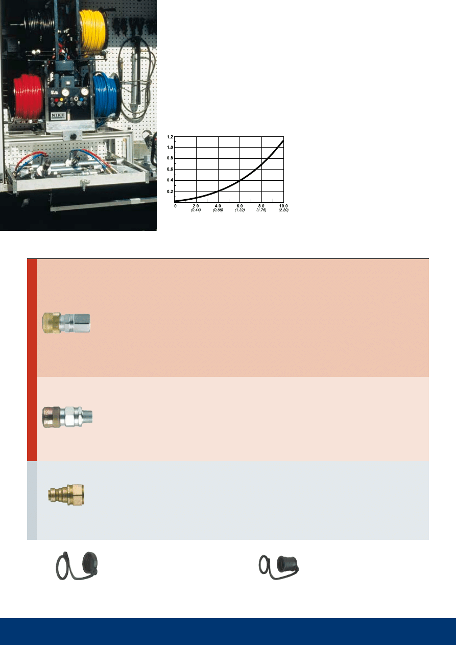
Technical data
Material: hardened, zinc chromate plated steel
Max. working pressure: 100 mpa
Min. bursting pressure: 260 MPa
Nominal flow diameter: 2.5 mm
(3/32")
Temperature range: - 30°C - + 100°C
(
-20°F - + 210°F)
Flow capacity at pressure drop 0.4 MPa:
6.0 l/min
(1.32 GPM UK)
The nipple should not be loaded while
disconnected, see also page 26.
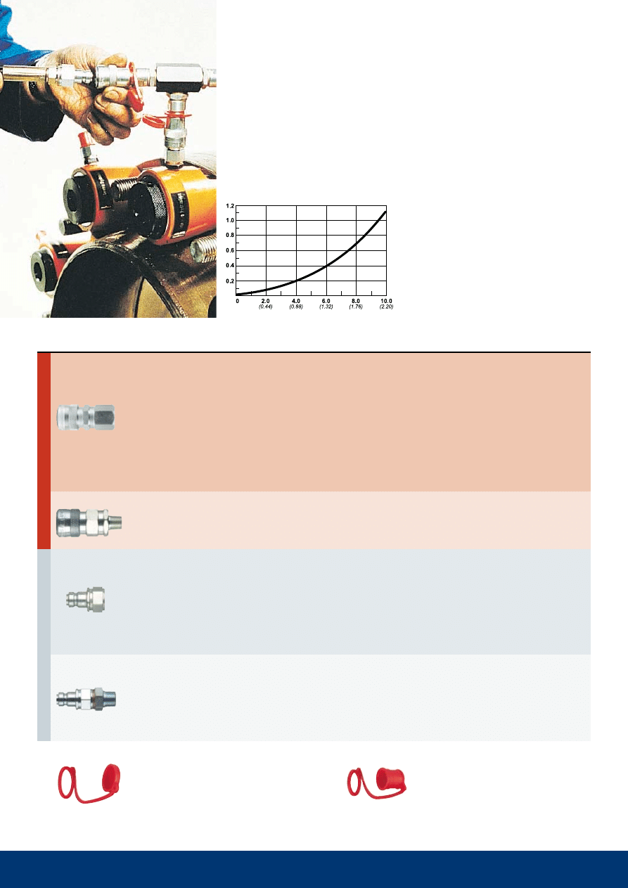
Series 115 is available in both standard and Flat-face designs (see page 9). The series is a CEJN
original with extremely small outside dimensions. Non-drip connection and disconnection are
standard on the CEJN high pressure range. All exposed components are made of zinc plated
steel. The coupling is also available in a design with a safety ring for the locking sleeve to
prevent accidental disconnection. Plastic dust caps are standard on both coupling and nipple
(dust caps of aluminum can be ordered separately). The nipple is also available in a design with
a hose rupture valve, part no. 10 115 6272. In the event of a ruptured hose the nipple closes and
prevents the system from being drained of oil, which could have critical consequences for
production and the environment. The hose rupture valve closes when the flow exceeds 13.0
liters/minute (2.86 GPM UK).
Series 115. 100 MPa.
pressure drop mpa
Flow l/min (GPM UK)
Plastic dust cap for couplings
Plastic dust cap for nipples
Part number 09 115 1002
Part number 09 115 1053
safety lock
safety lock
hose rupture valve
Rec.
Rec. Sealing
Part No.
Connection
Length
Diameter
Hexagon
Con. stroke
Weight (g)
torque (Nm)
method
N
ip
p
les
c
o
u
p
li
N
g
s
Female thread
male thread
Female thread
male thread
Thread connections are listed according to ISO Standards (see Page 23 for more information). All measurements are in mm (Dimension key, see page 25).
Pressure conversion table, see page 24. Check with your local retailer for availability and prices.
10 116 1201
G 1/8”
53,8
28,0
24
18,3
155
40-50
T
10 116 1202
G 1/4”
61,3
28,0
24
18,3
165
40-50
CMS
10 116 1222
G 1/4”
61,3
28,0
24
18,3
170
40-50
CMS
10 116 1230
G 1/4”
66,6
35
28
18,3
245
50-60
T (1*)
10 116 1246
G 1/4”
61,3
28,0
24
18,3
170
40-50
T
10 116 1402
NPT 1/4”
58,3
28,0
24
18,3
165
50-60
-
10 116 1422
NPT 1/4”
58,3
28,0
24
18,3
170
50-60
-
10 116 6201
G 1/8”
33,3
19,6
17
-
40
40-50
T
10 116 6202
G 1/4”
38,0
25,4
22
-
60
40-50
CMS
10 116 6241
G 1/4”
38,0
25,4
22
-
60
40-50
CMS
10 116 6402
NPT 1/4”
35,7
25,4
22
-
55
30-40
-
10 116 5252
G 1/4”
40,5
25,4
22
-
60
80-90
11
Plastic dust cap for couplings
Plastic dust cap for nipples
Part number 09 115 1004
Part number 09 115 1055
Technical data
Material: hardened, zinc chromate plated steel
Max. working pressure: 150 MPa
Min. bursting pressure: 300 mpa
Nominal flow diameter: 2.5 mm
(3/32")
Temperature range: - 30°C - + 100°C
(
-20°F - + 210°F)
Flow capacity at pressure drop 0.4 MPa:
6.0 l/min
(1.32 GPM UK)
The nipple should not be loaded while
disconnected, see also page 26.
Series 116 is available in both standard and Flat-face designs (see page 9). The series is a CEJN
original with extremely small outside dimensions. Non-drip connection and disconnection are
standard on the CEJN high pressure range. All exposed components are made of zinc plated
steel. The coupling is also available in a design with a safety ring for the locking sleeve to
prevent accidental disconnection. Plastic dust caps are standard on both coupling and nipple
(dust caps of aluminum can be ordered separately). There is a coupling and nipple manufactured
of stainless steel and chemically nickel-plated steel available for use in corrosive environments.
There is a coupling with a 90°-connection angle for use in confined areas. The range is primarily
recommended for cylinders, bolt tensioner tools, bearing pullers, etc.
Flow l/min (GPM UK)
pressure drop mpa
Series 116. 150 MPa.
safety lock
safety lock
angled connection
safety lock
stainless steel
(chemical nickel plated steel locking sleeve)
stainless steel valve
(chemical nickel plated steel body)
Rec.
Rec. Sealing
Part No.
Connection
Length
Diameter
Hexagon
Con. stroke
Weight (g)
torque (Nm)
method
N
ip
p
les
c
o
u
p
li
N
g
s
Female thread
Female thread
male thread
without valve
Washer (2*)
Thread connections are listed according to ISO Standards (see Page 23 for more information). All measurements are in mm (Dimension key, see page 25).
Pressure conversion table, see page 24. Check with your local retailer for availability and prices.
10 117 1202
G 1/4”
61.3
28.0
24
18.3
165
40-50
CMS
10 117 1232
G 1/4”
61.3
28.0
24
18.3
170
40-50
CMS
10 117 1404
NPT 3/8”
60.3
28.0
24
18.3
165
70-80
-
10 117 1434
NPT 3/8”
60.3
28.0
24
18.3
170
70-80
-
10 117 1254
G 3/8”
60.8
28.0
24
18.3
155
70-80
T
10 117 1454
NPT 3/8”
62.3
28.0
24
18.3
155
70-80
-
10 117 6202
G 1/4”
38.0
25.4
22
18.3
60
40-50
CMS
10 117 6404
NPT 3/8”
37.0
27.7
24
18.3
65
40-50
-
12
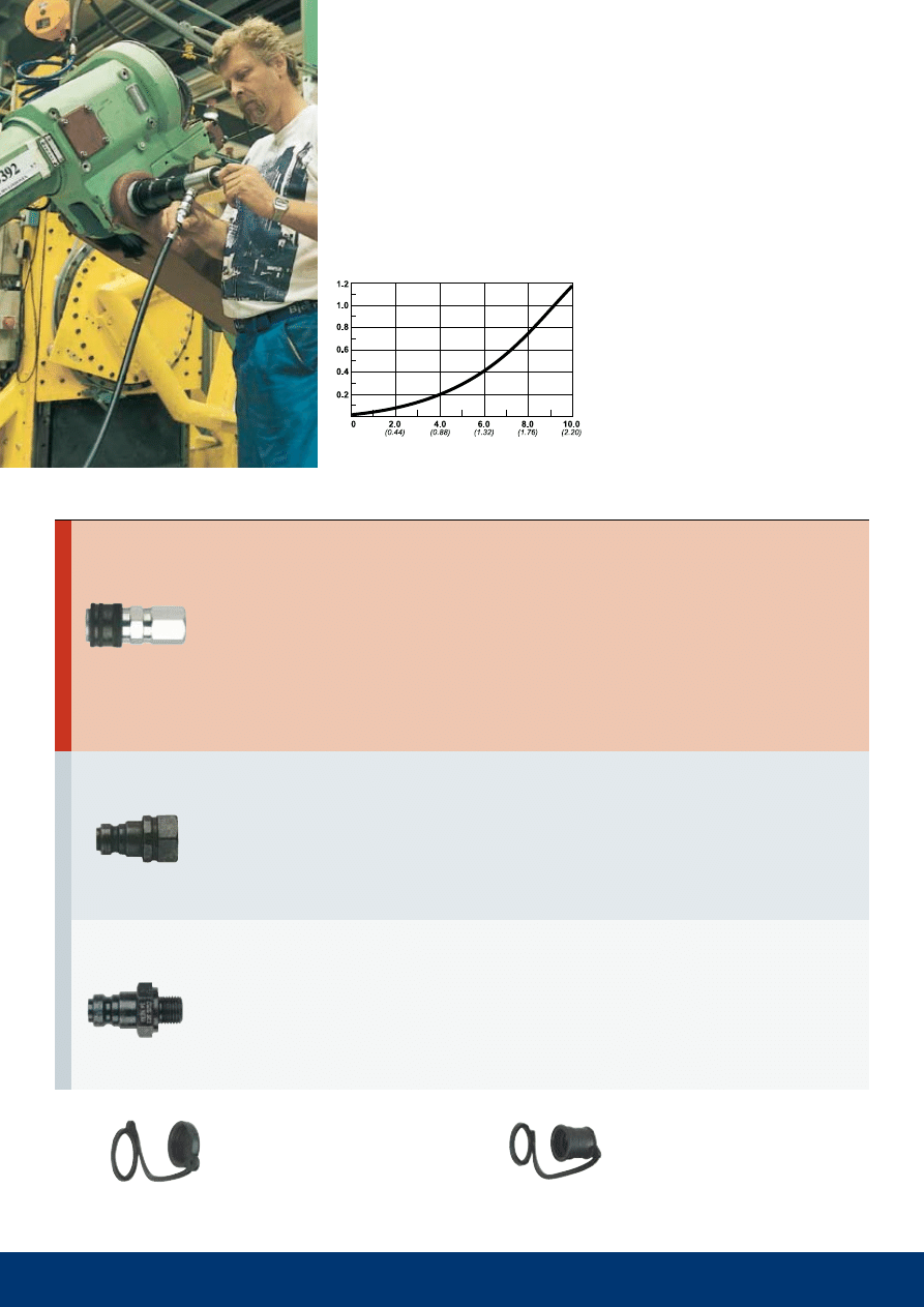
pressure drop mpa
Flow l/min (GPM UK)
Technical data
Material: hardened, zinc chromate plated steel
Max. working pressure: 100 mpa
Min. bursting pressure: 260 MPa
Nominal flow diameter: 2.5 mm
(3/32")
Temperature range: - 30°C - + 100°C
(
-20°F - + 210°F)
Flow capacity at pressure drop 0.4 MPa:
6.0 l/min
(1.32 GPM UK)
The nipple should not be loaded while
disconnected, see also page 26.
Series 117 is a sister coupling to series 115 and is used alongside the series 115 in applications
where the systems must not, under any circumstances, be interconnected. 115 and 117 offer
the same performance and qualities, but cannot be connected with one another, which makes
them an unbeatable combination for rescue tools, etc. All exposed components are made of
zinc plated steel. Plastic dust caps are standard on both coupling and nipple.
Series 117. 100 MPa.
Plastic dust cap for couplings
Plastic dust cap for nipples
Part number 09 115 1004
Part number 09 115 1055
safety lock
safety lock
Rec.
Rec. Sealing
Part No.
Connection
Length
Diameter
Hexagon
Con. stroke
Weight (g)
torque (Nm)
method
N
ip
p
les
c
o
u
p
li
N
g
s
Female thread
male thread
Female thread
Thread connections are listed according to ISO Standards (see Page 23 for more information). All measurements are in mm (Dimension key, see page 25).
Pressure conversion table, see page 24. Check with your local retailer for availability and prices.
10 218 1234
G 3/8”
73,4
34,6
30
20,1
340
70-80
T
10 218 1434
NPT 3/8"
73,4
34,6
30
20,1
330
70-80
-
10 218 6204
G 3/8”
50,5
27,7
24
-
115
70-80
T
10 218 6404
NPT 3/8"
49,0
27,7
24
-
110
40-50
-
13
Technical data
Material: hardened, zinc chromate plated steel
Max. working pressure: 100 mpa
Min. bursting pressure: 280 MPa
Nominal flow diameter: 4.5 mm (11/64")
Temperature range: - 30°C - + 100°C
(
-20°F - + 210°F)
Flow capacity at pressure drop 0.4 MPa:
15.0 l/min
(3.30 GPM UK)
The nipple should not be loaded while
disconnected, see also page 26.
The series 218 is a CEJN original that, despite very small outside dimensions, gives an
extremely high flow. Both the patented sealing design and non-drip connection and disconnec-
tion are standard on CEJN’s high pressure range. The coupling also has a safety ring for the
locking sleeve to prevent accidental disconnection. Plastic dust caps are standard on both cou-
pling and nipple. The series is an allround coupling that works well in most applications, even
if it is mainly recommended where large flow rates are required.
Series 218. 100 MPa.
pressure drop mpa
Flow l/min (GPM UK)
Plastic dust cap for couplings
Plastic dust cap for nipples
Part number 09 218 1000
Part number 09 218 1050
Rec.
Rec. Sealing
Part No.
Connection
Length
Diameter
Hexagon
Con. stroke
Weight (g)
torque (Nm)
method
N
ip
p
les
c
o
u
p
li
N
g
s
Female thread
Female thread
Thread connections are listed according to ISO Standards (see Page 23 for more information). All measurements are in mm (Dimension key, see page 25).
Pressure conversion table, see page 24. Check with your local retailer for availability and prices.
10 125 1202
G 1/4”
64.3
30.0
24
20.2
210
40-50
CMS
10 125 6202
G 1/4”
38.0
25.4
22
-
60
40-50
CMS
10 125 5252
G 1/4”
42.5
25.4
22
-
65
100-110
14
Technical data
Material: hardened, zinc chromate plated steel
Max. working pressure: 200 MPa
Min. bursting pressure: 400 mpa
Nominal flow diameter: 2.5 mm
(3/32")
Temperature range: - 30°C - + 100°C
(
-20°F - + 210°F)
Flow capacity at pressure drop 0.4 MPa:
5.8 l/min
(1.28 GPM UK)
The nipple should not be loaded while
disconnected. See also page 26.
Series 125 is a CEJN original with extremely small outside dimensions and a patented seal
design. Non-drip connection and disconnection are standard on the CEJN high pressure range.
All exposed components are made of zinc plated steel. Plastic dust caps are standard on both
coupling and nipple. The range is primarily recommended for nut runners, bearing pullers, etc.
pressure drop mpa
Flow l/min (GPM UK)
Series 125. 200 MPa.
Plastic dust cap for couplings
Plastic dust cap for nipples
Part number 09 115 1004
Part number 09 115 1055
Rec.
Rec. Sealing
Part No.
Connection
Length
Diameter
Hexagon
Con. stroke
Weight (g)
torque (Nm)
method
N
ip
p
les
c
o
u
p
li
N
g
s
Female thread
Female thread
male thread
without valve
Washer (2*)
Thread connections are listed according to ISO Standards (see Page 23 for more information). All measurements are in mm (Dimension key, see page 25).
Pressure conversion table, see page 24. Check with your local retailer for availability and prices.
10 135 1505
M16x1.5
64.0
30.0
22
20.6
210
40-50
10 135 6505
M16x1.5
55.3
25.0
22
-
125
40-50
10 135 6506
M16x1.5
55.3
25.0
22
-
125
40-50
15
Technical data
Material: Hardened black finish steel
Max. working pressure: 300 mpa
Min. bursting pressure: 600 MPa
Nominal flow diameter: 2.5 mm
(3/32")
Temperature range: -20°C - +80°C
(0°F - +175°F)
Flow capacity at pressure drop 0.4 MPa:
4.6 l/min
(1.01 GPM UK)
Max. recommended number of pressure cycles
with nipple 10 135 6505: 1000
with nipple 10 135 6506: 5000
Series 135 is a CEJN original for extremely high working pressure, 300 MPa. The series also
withstands pressure up to 300 MPa while disconnected (applies to the coupling and nipple).
Non-drip connection and disconnection are standard on the CEJN high pressure range. The
coupling also has a safety ring for the locking sleeve to prevent accidental disconnection.
Plastic dust caps are standard on both coupling and nipple. Swiveling can cause wear damage
over time why the nipple is available in both swivel and non-swivel designs. Each coupling
and nipple are pressure tested up to full working pressure before delivery. The series makes
it possible to connect pumps and accessories faster, safer and more conveniently, even at
extreme pressure. The series is in the first place recommended for bearing pullers, splitters and
hydraulic test installations.
Series 135. 300 MPa.
pressure drop mpa
Flow l/min (GPM UK)
Plastic dust cap for couplings
Plastic dust cap for nipples
Part number 09 140 1000
Part number 09 140 1050
Max. working pressure:
300 mpa
Seal material:
Nitrile rubber
Min. bursting pressure:
600 MPa
Flow diameter:
2.5 mm
(3/32")
Temperature range:
-20° C - +80° C (0°F - +175°F)
Max. no. of pressure cycles connected (to max. working pressure): 5000
Non-swivel model. Six optional positions are possible when connecting.
Max. working pressure:
300 mpa
Seal material:
Nitrile rubber
Min. bursting pressure:
600 MPa
Flow diameter:
2.5 mm
(3/32")
Temperature range:
-20° C - +80° C (0°F - +175°F)
Max. no. of pressure cycles connected (to max. working pressure): 1000
N
ip
p
les
c
o
u
p
li
N
g
s
Max. working pressure:
300 mpa
Seal material:
Nitrile rubber
Min. bursting pressure:
600 MPa
Flow diameter:
2.5 mm
(3/32")
Temperature range:
-20° C - +80° C (0°F - +175°F)
Max. no. of pressure cycles (to max. working pressure)
connected with
nipple 10 135 6505: 1000
nipple 10 135 6506: 5000
Rec.
Rec. Sealing
Part No.
Connection
Length
Diameter Key handle
Con. stroke
Weight (g)
torque (Nm)
method
Rec.
Rec. Sealing
Part No.
Connection
Length
Diameter Key handle
Con. stroke
Weight (g)
torque (Nm)
method
Rec.
Rec. Sealing
Part No.
Connection
Length
Diameter Key handle
Con. stroke
Weight (g)
torque (Nm)
method
female thread with 60°
sealing cone
(interchangeable with
both nipple designs)
Female thread with 60°
sealing cone
standard design
Female thread with 60°
sealing cone
Non-swivel design
Thread connections are listed according to ISO Standards (see Page 23 for more information). All measurements are in mm (Dimension key, see page 25).
Pressure conversion table, see page 24. Check with your local retailer for availability and prices.
10 230 1452
NPT 1/4"
60.8
28.0
22
18.8
120
50-60
-
10 230 1484
NPT 3/8"
72.3
35.0
24
25.4
220
70-80
-
10 230 6402
NPT 1/4"
32.5
28.0
19
-
75
50-60
-
10 230 6434
NPT 3/8"
40.0
35.0
32
-
140
70-80
-
16
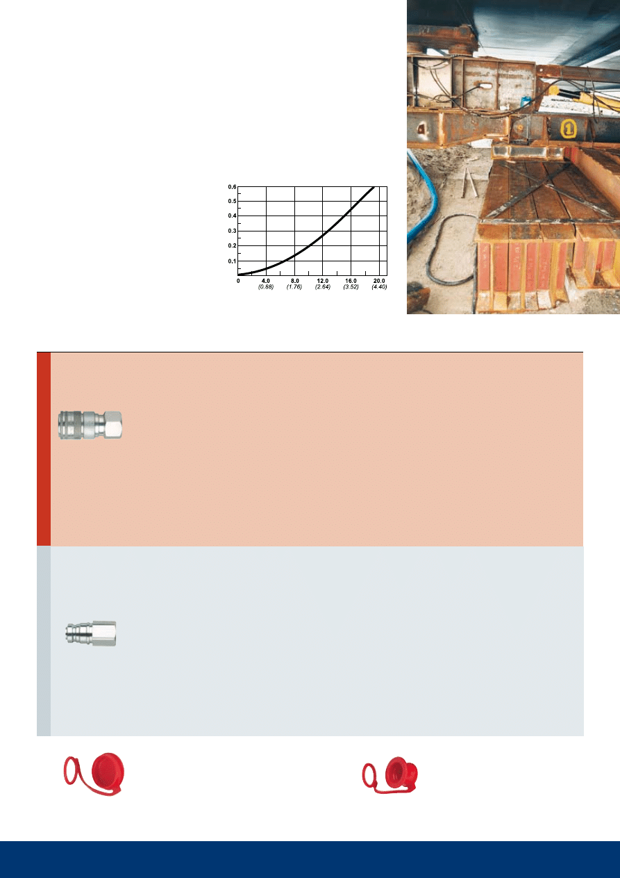
Technical data
Material, coupling: Zinc plated steel
Material, dust cap: steel
Seal: Nitrile NBR
Max. working pressure: 70 mpa
Min. bursting pressure:
Connected:
1/4” 220 MPa
3/8” 185 MPa
Coupling disconnected: 1/4” 180 MPa
3/8” 185 MPa
Nipple disconnected: 1/4” 149 MPa
3/8” 150 MPa
Nominal flow diameter: 1/4" 5 mm, 3/8" 7 mm
Flow capacity at pressure drop 0.4 MPa:
1/4” 16.1 l/min
(3.54 GPM UK)
3/8” 21.2 l/min (4.64 GPM UK)
Temperature range: -30°C - +100°C
(-20°F - + 210°F)
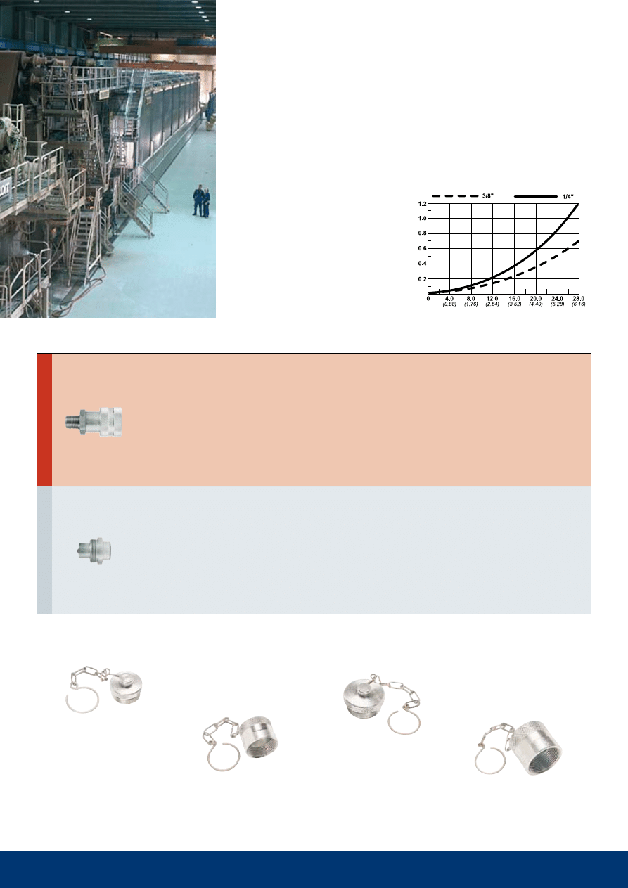
Series 230 is a screw-to-connect series and a good complement to CEJN’s large range of quick connect
couplings. The series is also characterised by CEJN’s quality approach and has a high flow rate capacity.
The series can be connected under pressure and is interchangeable with most screw-to-connect couplings.
Hand pumps, cylinders and jacks are just a few examples of application areas.
Series 230. 70 MPa.
Screw-to-connect couplings.
10 230 4101
For 1/4” coupling 10 230 1452
10 230 4100
For 1/4” nipple 10 230 6402
10 230 4103
For 3/8” coupling 10 230 1484
10 230 4102
For 3/8” nipple 10 230 6434
Dust caps
pressure drop mpa
Flow l/min (GPM UK)
Rec.
Rec. Sealing
Part No.
Connection
Length
Diameter
Hexagon
Con. stroke
Weight (g)
torque (Nm)
method
N
ip
p
les
c
o
u
p
li
N
g
s
male thread
Female thread
Thread connections are listed according to ISO Standards (see Page 23 for more information). All measurements are in mm (Dimension key, see page 25).
Pressure conversion table, see page 24. Check with your local retailer for availability and prices.
17
Thread connections are listed according to ISO Standards (see page 23 for more information). All measurements are in mm (Dimension key, see page 25).
Pressure conversion table, see page 24. Check with your local retailer for availability and prices.
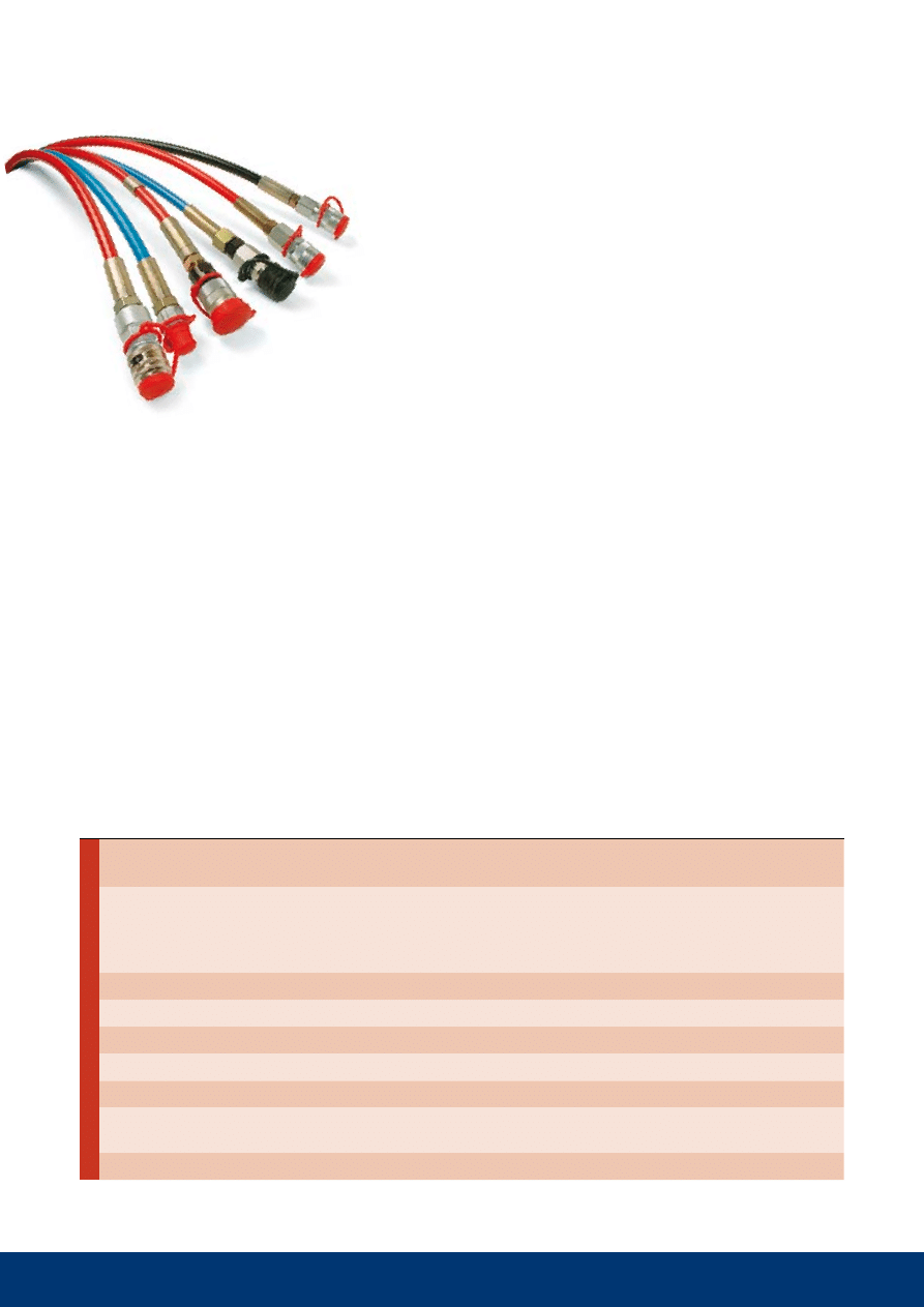
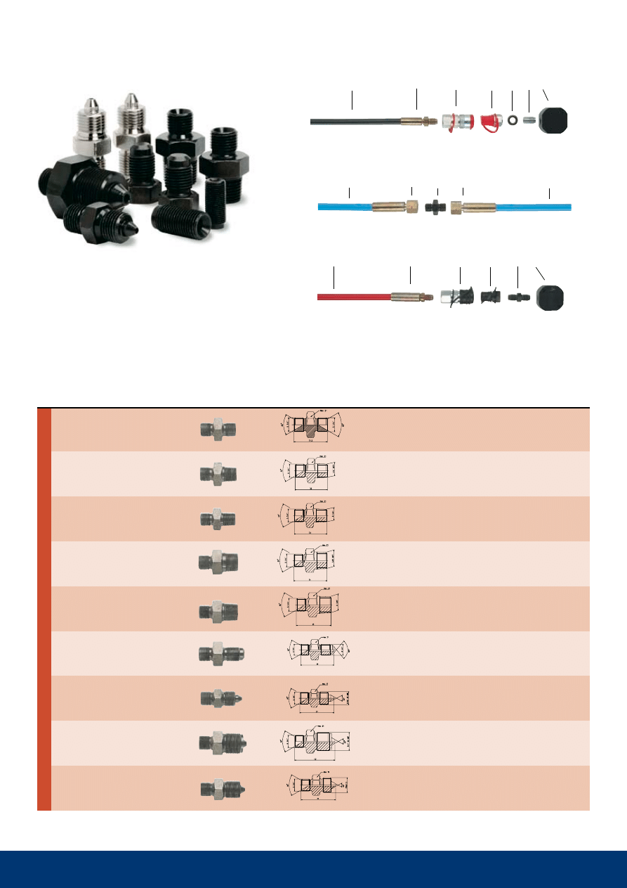
Pre-Assembled Hose Kits
PRESSURE TESTED AND READy TO USE
The range of CEJN high-pressure hose is like the rest
of the CEJN product range a testament to quality and
performance. Only the best is sold under the CEJN brand and
this range is clearly part of that tradition. The range contains four
hoses with different pressure ratings up to 250 MPa. With a large
variety of fittings to choose from, hose kits can be assembled to meet
almost all requests.
Advantages!
• Ultra-high working pressures
• Maintained flexibility through
entire service life
• Low volumetric expansion
• Smooth inner bores
• Kink-resistant steel-reinforced
construction
• Abrasion-resistant covers
• Small outside diameter
• Superior chemical resistance
Hose
CEJN 700
CEJN 1000
CEJN 1800
CEJN 2500
Part no.:
Hose
Hose – Twin design
19 951 0701 (Red)
19 951 0710 (Red/Yellow)
19 951 1001 (Black)
19 951 1010 (Red/Blue)
19 951 1801 (Blue)
–
19 951 2501 (Red)
–
Design:
Inner tube of polyamide
(PA), 2 spiral layers of high
tensile steel wire, 2 open
spiral synthetic fibre, outer
sheath of polyurethane
(PUR)
Inner tube of polyamide
(PA), 4 layers of spiral
wound steel wire, outer
sheath of polyurethane
(PUR)
Inner tube of
polyoxymethylene (POM),
4 spiral layers of high
tensile steel wire, outer
sheath of polymide (PA)
Inner tube of
polyoxymethylene (POM),
6 spiral layers of high
tensile steel wire, outer
sheath of polymide (PA)
Max. working pressure:
70 MPa (10,150 PSI)
100 MPa (14,500 PSI)
180 MPa (26,100 PSI)
250 MPa (36,250 PSI)
Min. burst pressure:
186 MPa (26,970 PSI)
320 MPa (46,600 PSI)
450 MPa (65,250 PSI)
625 MPa (90,620 PSI)
I.D. x O.D.:
6.3 x 12.4 mm
6.3 x 13.3 mm
4.7 x 11.5 mm
4.7 x 13.0 mm
Min. bend radius:
70 mm
80 mm
130 mm
175 mm
Weight:
190 g/m
305 g/m
280 g/m
410 g/m
Temperature range:
-40°C to +100°C
(-40°F to +212°F)
-40°C to +100°C
(-40°F to +212°F)
-40°C to +100°C
(-40°F to +212°F)
-40°C to +100°C
(-40°F to +212°F)
Other information: Other colors upon request
Benefits!
The CEJN High-Pressure hose is a spiralized steel reinforced poly-
mer hose that picks up where conventional product capabilities stop.
It gives you ultra-high working pressure with maintained flexibility
through entire life. Its low volumetric expansion gives fast response
time in hydraulic systems while the smooth inner bores provide a
minimized pressure drop. A long-lasting service time and extended
hose life in even the toughest applications is a result of the kink-
resistant steel-reinforced construction, abrasion-resistant covers and
a superior chemical resistance. The small outside diameter makes the
hose ideal for tight routing.
19 951 0730
19 951 1830
–
19 951 0731
–
–
19 951 0732
19 951 1832
19 951 2530
19 951 0733
19 951 1831 *
19 951 2534
19 951 0734
–
–
19 951 0735
–
–
19 951 0740
–
–
19 951 0741
–
–
19 951 0736
–
–
19 951 0737
19 951 1833
19 951 2531
–
–
19 951 2533
19 951 0738
–
–
–
–
19 951 2532
19 951 0739
–
–
19 951 1080
–
–
19 951 1081
–
–
–
19 951 1880
–
09 950 4600
19 950 0062
19 950 0083
19 950 0084
10 230 1452
10 230 6402
19 951 0734
10 115 1202
19 951 0732
10 115 6202
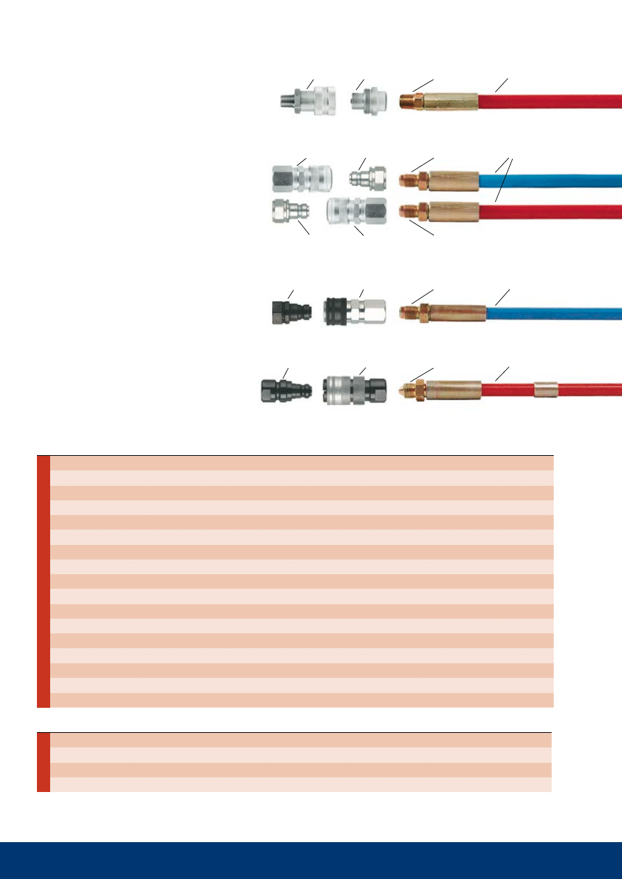
ceJN 700
CEJN 1800
CEJN 2500
10 135 6506
10 135 1505
19 951 2533
10 125 1202
10 125 6202
19 951 1832
10 115 6202
19 951 0732
10 115 1202
18
G 1/4” male with 60° int. sealing cone + recess for Tredo ring
G 1/4” male with recess for USIT ring
G 1/4” male with 120° ext. sealing cone (CMS)
G 1/4” male flat end for copper washer (*with recess for USIT ring)
1/4” NPT male
3/8” NPT male
3/8” NPT female
R 1/4" male
R 3/8” male
Sealing head (60°) + G 1/4” female swivel nut
M16 x 1.5 male with 60° ext. cone
Sealing head (60°) + M14 x 1.5 female swivel nut
59° ext. sealing cone + 9/16”-18 UNF female swivel nut
24° ext. sealing cone with O-ring + M18 x 1.5 female swivel nut
kink-protection spring
Clamb for twin-hose
protection hose pvc
Hose kits to fit your needs
Opportunities!
Each hose kit is assembled to your order. The
hose can be cut in any length and assembled
with a large variety of fittings and couplings/
nipples. CEJN’s series of high performance
high-pressure hydraulic couplings are an
excellent complement and can be included
in any hose kit. Before delivery each kit is
pressure tested for safety and performance.
When delivered the kits are ready to be used
without further assembly, tests or checks,
making it a perfect choice to save time and
cost. Four hoses with different pressure ratings,
a large range of fittings and several high per-
forming couplings make CEJN High-pressure
hose kits a perfect choice for most applica-
tions. Below is a condensed list of hose and
fittings, more options are available on request.
ceJN 1000, twin design
End connections, Part no.
70/100 MPa
180 MPa
250 MPa
cupper washer
Tredo ring (rubber/metal seal) for G 1/4"
Tredo ring (rubber/metal seal) for G 1/4", high strength steel
USIT ring (rubber/metal seal) for G 1/4"
Accessories
Part no.
Thread connections are listed according to ISO Standards (see page 23 for more information). All measurements are in mm (Dimension key, see page 25).
Pressure conversion table, see page 24. Check with your local retailer for availability and prices.
19 940 2120 G 1/4"
1000 (14 500)
22
42
9,5
62
64
52
13
-
-
-
14
19 940 2121 NPT 1/4”
1000 (14 500)
22
42
9,5
62
64
52
13
-
-
-
14
19 940 2320 G 1/4"
1000 (14 500)
5
32
0
62
68
55
13
85
3,6
75
14
19 940 2321 NPT 1/4”
1000 (14 500)
5
32
0
62
68
55
13
85
3,6
75
14
19 940 3120 G 1/2”
1000 (14 500)
17,5 49,5 15,5
99
101
87
20
-
-
-
22
19 940 3140 NPT 1/2”
1000 (14 500)
17,5 49,5 15,5
99
101
87
20
-
-
-
22
19 940 3121 G 1/2”
1600 (23 200)
17,5 49,5 15,5
99
101
87
20
-
-
-
22
19 940 3122 G 1/2”
2060 (29 870)
17,5 49,5 15,5
99
101
87
20
-
-
-
22
19 940 3320 G 1/2”
1000 (14 500)
6
54
30
101
101
85,5 20
132
4,8
116
22
19 940 3321 G 1/2”
1600 (23 200)
6
54
30
101
101
85,5 20
132
4,8
116
22
19 940 3322 G 1/2”
2060 (29 870)
6
54
30
101
101
85,5 20
132
4,8
116
22
19 940 4120 G 1/2”
1000 (14 500)
17,5 49,5 15,5
159
161
118
20
-
-
-
22
19 940 4121 G 1/2”
1600 (23 200)
17,5 49,5 15,5
159
161
118
20
-
-
-
22
19 940 4122 G 1/2”
2060 (29 870)
17,5 49,5 15,5
159
161
118
20
-
-
-
22
19 940 4320 G 1/2”
1000 (14 500)
10
49,5
50
159
161
82
20
196
5,8
178*
22
19 940 4321 G 1/2”
1600 (23 200)
10
49,5
50
159
161
82
20
196
5,8
178*
22
19 940 4322 G 1/2”
2060 (29 870)
10
49,5
50
159
161
82
20
196
5,8
178*
22
Ø
1
60
M
M
Ø
1
60
M
M
Ø
1
00
M
M
Ø
1
00
M
M
Ø
6
3
M
M
Ø
6
3
M
M
19
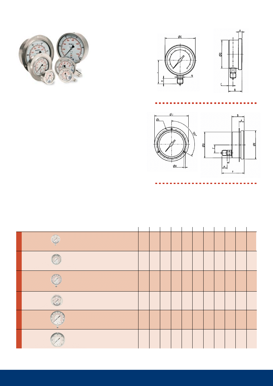
Series 940. Pressure gauges.
CEJN’s range comprises of both bottom and panel
mounted pressure gauges in models up to 2000 bar
(200 MPa). All models are glycerine filled for improved
performance and long life. The gauges are made of
stainless steel, which means they can be used in dirty
and rugged environments. The pressure gauges can be
connected by means of a porting block (see page 22).
Technical data
Max. recommended working pressure:
75% of the full scale range.
Material: Stainless steel AISI 316 and AISI 304.
Dial face of aluminium with black graduations.
pointer of aluminium or stainless steel.
gasket of polychloroprene.
window of plexiglass.
Units: bar and PSI.
Protection class: IP 65.
Liquid filled with 98% glycerine.
Accuracy: Ø 63 mm +- 1.6% of full scale.
Ø 100 and 160 mm +- 1% of full scale.
Temperature range: +15° C - +65° C (+60°F - +150° F).
Miscellaneous: Ø 100 and 160 mm manufactured
in accordance with EN 837-1.
Panel mounting, rear connection.
Ø 63 mm (connection in the center of the housing).
Ø 100 mm. Ø 160 mm.
Bottom connection.
Ø 63 mm. Ø 100 mm. Ø 160 mm.
Bottom connection
male thread
panel mounting
male thread
Bottom connection
male thread
panel mounting
male thread
Bottom connection
male thread
panel mounting
male thread
*
not
in
accordance
with
EN
837-1
Part No.
Connection Scale max. work
Dimensions mm
pressure bar (PSI)
A
B
C
D
E
F
H
J
K
L
N
Thread connections are listed according to ISO Standards (see page 23 for more information). All measurements are in mm (Dimension key, see page 25).
Pressure conversion table, see page 24. Check with your local retailer for availability and prices.
1
2
3
4
5
1
2
3
4
5
6 7
1
2
3
4
5
6
19 950 1622
19 950 1623
100 mpa
19 950 1621
100 mpa
19 950 1603
100 mpa
19 950 1604
100 mpa
19 950 1602
200 MPa
19 950 1605
200 MPa
19 950 1606
200 MPa
19 950 1607
200 MPa
20
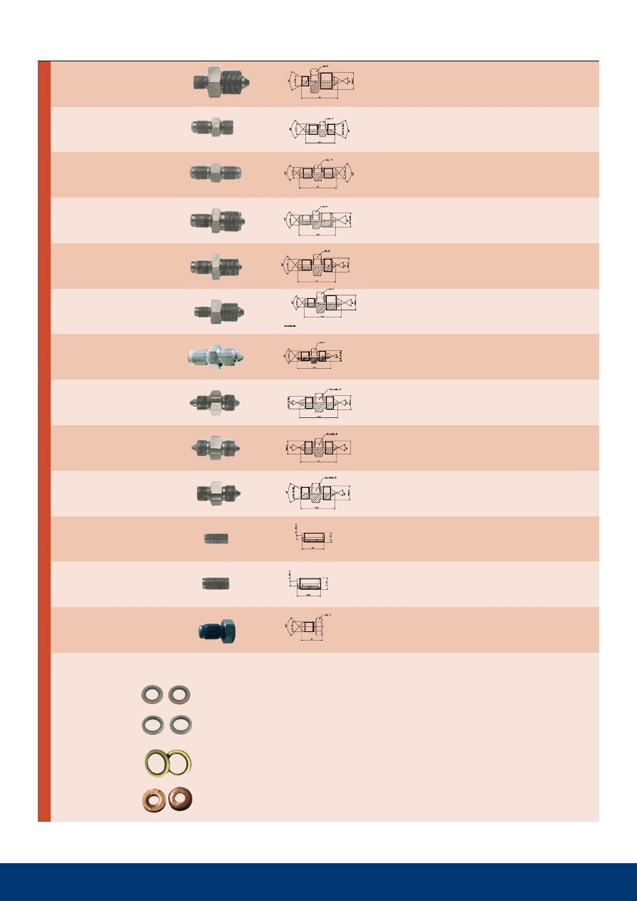
A safe and trouble free connection is essential in all situ-
ations. CEJN’s extensive range of adapters cover a very
wide connection range suitable for most couplings and
hoses. All adapters are manufactured of black-zinc plated
steel. Working pressure varies between 100 MPa and 300
MPa, see product table for data on respective adapters.
Series 950. Adapters.
100-300 MPa
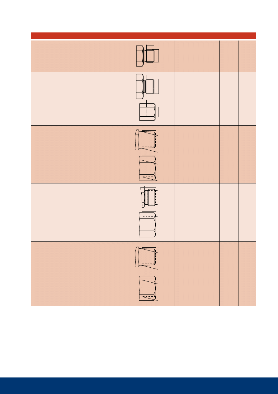
1. G 1/4” male thread with 60° internal cone .
2. G 1/4” male thread with 60° internal cone
1. G 1/4” male thread with 60° internal cone
2. NPT 1/4” male thread
1. G 1/4” male thread with 60° internal cone
2. R 1/4” male thread
1. G 1/4” male thread with 60° internal cone
2. NPT 3/8” male thread
1. G 1/4” male thread with 60° internal cone
2. R 3/8” male thread
1. G 1/4” male thread with 60° internal cone
2. G 1/4” male thread with 120° external cone
1. G 1/4” male thread with 60° internal cone
2. 9/16”-18 UNF thread with 60° external cone
1. G 1/4” male thread with 60° internal cone
2. 3/4”-16 UNF male thread with 60° external cone
1. G 1/4” male thread with 60° internal cone
2. M16x1.5 male thread with 60° external cone
Part No.
Max. Rec. Working pressure.
Connection 1
Connection 2
Key
Thread connections are listed according to ISO Standards (see Page 23 for more information). All measurements are in mm (Dimension key, see page 25).
Pressure conversion table, see page 24. Check with your local retailer for availability and prices.
with rubber metal seal 100 MPa
with 24/60° cone 200 MPa
1. Hose type CEJN 1800
2. 1/4” G thread, female swivel with 24°/60°
ext. cone part no. 19 951 1833
3. Adapter part no. 19 950 1622
4. 1/4” G thread, female swivel with 24°/60°
ext. cone part no. 19 951 1833
5. Hose type CEJN 1800
1. Hose type CEJN 2500
2. 1/4" G male thread with 120° ext. sealing cone
CEJN metal seal part no. 19 951 2530
3. Coupling part no. 10.125 1202
4. Nipple part no. 10.125 6202
5. Adapter part no. 19 950 1601
6. Porting block part no. 19 950 1680
1. hose type ceJN 1000
2. 1/4” G male thread with 120° ext. sealing cone
(CMS) part no. 19 951 0732
3. Coupling part no. 10.115 1202
4. Nipple part no. 10 115 6202
5. Rubber metal seal part no. 19 950 0062
6. Adapter part no. 19 950 0015
7. Porting block part no. 19 950 1680
19 950 1608
200 MPa
19 950 0029
200 MPa
19 950 1601
300 mpa
19 950 1611
200 MPa
19 950 1610
300 mpa
19 950 1609
200 MPa
19 950 0022
300 mpa
19 950 1613
300 mpa
19 950 1612
300 mpa
19 950 1614
200 MPa
19 950 0016
100 mpa
19 950 0015
100 mpa
19 950 1600
300 mpa
21
Part No.
Max. Rec. Working pressure.
Connection 1
Connection 2
Key
Rubber metal seals
Part number
Size
Max. working pressure
tredo
19 950 0061
1/8”
100 MPa
19 950 0062
1/4”
100 MPa
19 950 0064
3/8”
100 MPa
high strength
19 950 0083
1/4”
150 MPa
Bursting pressure 260 MPa
usit
19 950 0084
1/4”
100 mpa
Cupper washer
09 950 4600
1/4”
200 MPa
1. G 1/4” male thread with 60° internal cone
2. M22x1.5 male thread with 60° external cone
1. G1/4” male thread with 120° external cone
2. 9/16”-18 UNF male thread with 60° internal cone
1. G 1/4” male thread with 120° external cone
2. G 1/4” male thread with 120° external cone
1. G 1/4” male thread with 120° external cone
2. 3/4”-16 UNF male thread with 60° external cone
1. G1/4” male thread with 120° external cone
2. M16x1.5 male thread with 60° external cone
1. G 1/4” male thread with 120° external cone
2. M22x1.5 male thread with 60° external cone
1.
G 1/4” male thread with 120° external cone
2.
9/16”-18 UNF male thread with 60° external cone
1. 9/16”-18 UNF male thread with 60° external cone
2. M16x1.5 male thread with 60° external cone
1. M16x1.5 male thread with 60° external cone
2. M16x1.5 male thread with 60° external cone
1. 9/16”-18 UNF male thread with 60° internal cone
2. M16x1.5 male thread with 60° external cone
G 1/8” male, fully threaded
G 1/4” male, fully threaded
1.
G 1/4” male thread with 120° external cone
2. -
Thread connections are listed according to ISO Standards (see Page 23 for more information). All measurements are in mm (Dimension key, see page 25).
Pressure conversion table, see page 24. Check with your local retailer for availability and prices.
19 950 1680
19 950 1682
19 950 1681
19 950 1683
19 950 1684
19 950 1600
22
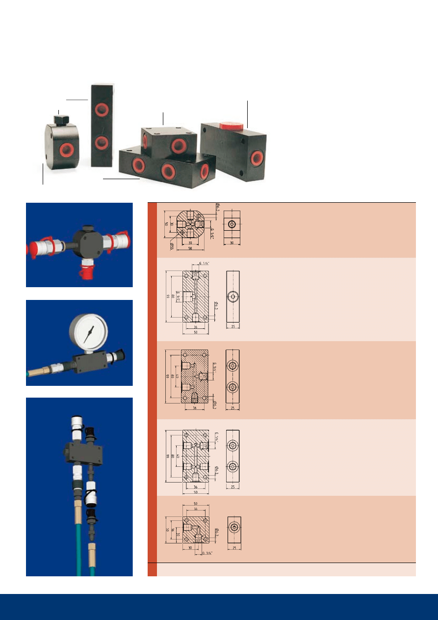
Series 950. Porting blocks
300 MPa.
CEJN’s porting blocks make it possible
to utilise/connect several hydraulic lines
from a single pump to numerous tools
as well as the possibility of connecting a
pressure gauge. The blocks are available
in five different sizes and designs with a
varying number of ports, see the product
table for data on respective blocks. Five
different blocks all in black-zinc plated
steel. Flow diameter: 5 mm (3/16").
Blind plug
19 950 1600
G 1/4” male with 120° sealing cone (CMS)
19 950 1680
4-way
distribution block
19 950 1681
3-way
gauge block
19 950 1682
3-way
distribution block
19 950 1683
5-way
distribution block
19 950 1684
2-way L-Block
G 1/4” female thread
seal with
120° sealing cone
or rubber metal seal
supplied with
one blind plug
G 1/4” female thread
seal with
120° sealing cone
or rubber metal seal
gauge connection
G 1/2”
supplied with
sealing washer
G 1/4” female thread.
seal with
120° sealing cone
or rubber metal seal
G 1/4” female thread.
seal with
120° sealing cone
or rubber metal seal
G 1/4” female thread.
seal with
120° sealing cone
or rubber metal seal
300 mpa
(100 mpa with
rubber metal seal)
200 MPa
(100 mpa with
rubber metal seal)
300 mpa
(100 mpa with
rubber metal seal)
300 mpa
(100 mpa with
rubber metal seal)
300 mpa
(100 mpa with
rubber metal seal)
POR
TING
BLOCKS
Max. Working
Part No.
Connection
pressure.
Thread connections are listed according to ISO Standards (see Page 23 for more information). All measurements are in mm (Dimension key, see page 25).
Pressure conversion table, see page 24. Check with your local retailer for availability and prices.
23
Maintanence Advise -
high pressure hydraulics couplings and Nipples
To guarantee a coupling’s function, quality and lifetime, be sure to:
• Dynamic load on nipple while disconnected may lead to seal damage causing leakage in disconnected position. Min. burst
pressure on disconnected nipple is always the same as for the corresponding coupling.
• Never over-load the products. Check max.working pressure from catalogue (stated min. burst pressure is only valid for new
products that have not been exposed to over-load, impacts, corrosion etc.)
• Keep the coupling and nipple clean and dry. Wipe them off before connection.
• Put the dust caps on when coupling and nipple are in disconnected position.
• In order to keep the dust caps clean, connect them together when coupling and nipple are in connected position.
• Avoid front-end impacts to the coupling and nipple.
• Check the sealing of the coupling and its moving parts regularly. If necessary, replace the coupling.
• Check the nipples on a regular basis. If they are heavily worn or marked, replace them. Worn nipples lead to greater wear on
the couplings.
• Choose the proper connection for the application. Oversized connections cause unnecessary wear to the coupling.
Technical Data
– measurement and units
Oil flow: .................................The oil flow is measured within an accuracy of ±5%. The flow rate is valid at viscosity 30 cSt
(30 mm2/s)
Working pressure: ..............specified in mpa. the working pressure is often stipulated in the varying national and international
standards for quick connect coupling.
Burst pressure: ....................Specified in MPa and measured with an accuracy of ±3%.
Weight: .................................The weight is measured in "g" (gram) as an average of 10 pcs.
Temperature range: ............The temperature is measured in Celsius degrees within an accuracy of ±2°C (±3.6°F).
compressed air,
oil, water
chemicals, hot air
water
All technical data are measured according to CEJN standards. Contact CEJN for more detailed information.
T - Rubber metal seal, see page 21.
CMS - CEJN Metal Seal (120° cone)
1* = High strength rubber metal seal 19 950 0083
2* = Copper seal 09 950 4600
Sealing Materials
MATERIALS
FEATURES
TEMPERATURE RANgE
MEDIA
resistant to water, gasoline, grease, mineral
oil, heat, and alkalis. sensitive to ozone.
recommended for gasoline, oils, and acids.
weather-resistant. Not recommended for hot
steam.
Suitable for hot water, alkalines, and acids.
Not recommended for mineral oil.
-30°C to +100°C
(-22°F to +212°F)
-15°C to +200°C
(-5°F to +392°F)
-40°C to +150°C
(-40°F to +302°F)
NBR
(Nitrile rubber
Buna-N)
FPM
(Fluorocarbon
rubber Viton
®
)
EPDM
(ethylene propylene
rubber EPDM/EPM)
Contact CEJN for more detailed information regarding sealing material and chemical compatibility with CEJN couplings.
Table key for pages 9-22
– sealing method and dimensions
connection stroke
Nipple
hexagon
Ø coupling
coupling
hexagon
Ø Nipple
24
Units, Conversion Tables, and Formulas
Pressure
FROM
TO
MULTIPLy By
ExAMPLE
atm
(atmosphere)
bar
1.01325
1.1 atm x 1.01325 = 1.115 bar
atm
MPa
0.10132
1.1 atm x 0.10132 = 0.111 MPa
atm
PSI
14.696
1.1 atm x 14.695 = 16.166 PSI
bar
atm
0.98692
10 bar x 0.98692 = 9.8692 atm
bar
MPa
0.1
10 bar x 0.1 = 1.0 MPa
bar
PSI
14.504
10 bar x 14.504 = 145 PSI
mpa
(megapascal)
atm
9.8692
10 MPa x 9.8692 = 98.692 atm
MPa
bar
10
10 MPa x 10 = 100 bar
MPa
PSI
145.0
10 MPa x 145.0 = 1450 PSI
psi
(pounds / square inch)
atm
0.068
100 PSI x 0.068 = 6.80 atm
PSI
bar
0.0689
100 PSI x 0.0689 = 6.89 bar
PSI
MPa
0.00689
100 PSI x 0.00689 = 0.689 MPa
Flow
FROM
TO
MULTIPLy By
ExAMPLE
Volume
FROM
TO
MULTIPLy By
ExAMPLE
cFm
(cubic feet / minute)
l/min
28.32
100 CFM x 28.32 = 2832 l/min
CFM
l/s
0.472
100 CFM x 0.472 = 47.2 l/s
cFm
m
3
/h
1.699
100 CFM x 1.699 = 169.9 m
3
/h
l/min
(liter / minute)
CFM
0.0353
100 l/min x 0.0353 = 3.5 CFM
l/min
l/s
0.0167
100 l/min x 0.0167 = 1.7 l/s
l/min
m
3
/h
0.06
100 l/min x 0.06 = 6 m
3
/h
l/s
(liter / second)
CFM
2.119
10 l/s x 2.119 x 21.2 CFM
l/s
l/min
60
10 l/s x 60 = 600 l/min
l/s
m
3
/h
3.6
10 l/s x 3.6 = 36 m
3
/h
m
3
/h
(cubic meter / hour)
CFM
0.5885
10 m
3
/h x 0.5885 = 5.885 CFM
m
3
/h
l/min
16.667
10 m
3
/h x 16.667 = 166.7 l/min
m
3
/h
l/s
0.2777
10 m
3
/h x 0.2777 = 2.777 l/s
ft
3
(cubic foot)
gl UK
6.228
10 ft
3
x 6.228 = 62.28 gl UK
ft
3
gl U.S.
7.48
10 ft
3
x 7.48 = 74.8 gl U.S.
ft
3
l
28.32
10 ft
3
x 28.32 = 283.2 l
ft
3
m
3
0.0283
10 ft
3
x 0.0283 = 0.283 m
3
gl uk
(gallon UK)
ft
3
0.1605
10 gl UK x 0.1605 = 1.605 ft
3
gl UK
gl U.S.
1.2009
10 gl UK x 1.2009 = 12.009 gl U.S.
gl UK
l
4.546
10 gl UK x 4.546 = 45.46 l
gl uk
m
3
0.0045
10 gl UK x 0.0045 = 0.045 m
3
gl u.s.
(gallon U.S.)
ft
3
0.1336
10 gl U.S. x 0.1336 = 1.336 ft
3
gl U.S.
gl UK
0.8326
10 gl U.S. x 0.8326 = 8.326 gl UK
gl U.S.
l
3.785
10 gl U.S. x 3.785 = 37.85 l
gl u.s.
m
3
0.0037
10 gl U.S. x 0.0037 = 0.037 m
3
l
(liter)
ft
3
0.0353
100 l x 0.0353 = 3.53 ft
3
l
gl UK
0.220
100 l x 0.220 = 22.0 gl UK
l
gl U.S.
0.264
100 l x 0.264 = 26.4 gl U.S.
l
m
3
0.001
100 l x 0.001 = 0.1 m
3
m
3
(cubic meter)
ft
3
35.3
10 m
3
x 35.3 = 353 ft
3
m
3
gl UK
219.96
10 m
3
x 219.96 = 2199.6 gl UK
m
3
gl U.S.
264.17
10 m
3
x 264.17 = 2641.7 gl U.S.
m
3
l
1000
10 m
3
x 1000 = 10 000 l
Force
FROM
TO
MULTIPLy By
ExAMPLE
lbf
(pound force)
kp
0.454
10 lbf x 0.454 = 4.54 kp
lbf
N
4.448
10 lbf x 4.448 = 44.48 N
kp
(kilogram force)
lbf
2.205
10 kp x 2.205 = 22.05 lbf
kp
N
9.806
10 kp x 9.806 = 98.06 N
N
(newton)
lbf
0.2248
10 N x 0.2248 = 2.25 lbf
N
kp
0.1020
10 N x 0.1020 = 1.02 kp
25
Application guide
Mass
FROM
TO
MULTIPLy By
ExAMPLE
Torque
FROM
TO
MULTIPLy By
ExAMPLE
kpm
(kilo pound meter)
lbfft
7.233
10 kpm x 7.233 = 72.33 lbfft
kpm
Nm
9.81
10 kpm x 9.81 = 98.1 Nm
lbfft
(pound force foot)
Nm
1.356
10 kpm x 1.356 = 13.56 Nm
lbfft
Nm
0.1383
10 kpm x 0.1383 = 1.38 kpm
Nm
(newton meter)
kpm
0.1020
10 Nm x 0.1020 = 1.02 kpm
Nm
lbfft
0.7376
10 Nm x 0.7376 = 7.38 lbfft
Length
FROM
TO
MULTIPLy By
ExAMPLE
ft
(foot)
inch
12
10 ft x 12 = 120 inch
ft
m
0.3048
10 ft x 0.3048 = 3.048 m
ft
mm
304.8
10 ft x 304.8 = 3048 mm
inch
ft
0.0833
10 inch x 0.0833 = 0.833 ft
inch
m
0.0254
10 inch x 0.0254 = 0.254 m
inch
mm
25.4
10 inch x 25.4 = 254 mm
m
(meter)
ft
3.28083
10 m x 3.28083 = 32.8083 ft
m
inch
39.3699
10 m x 39.3699 = 393.699 inch
m
mm
1000
10 m x 1000 = 10 000 mm
mm
(millimeter)
ft
0.00328
10 mm x 0.00328 = 0.0328 ft
mm
inch
0.0393
10 mm x 0.0393 = 0.393 inch
mm
m
0.001
10 mm x 0.001 = 0.01 m
g
(gram)
kg
0.001
10 g x 0.001 = 0.01 kg
g
lb
0.0022
10 g x 0.0022 = 0.022 lb
g
oz
0.0352
10 g x 0.0352 = 0.352 oz
kg
(kilogram)
g
1000
10 kg x 1000 = 10 000 g
kg
lb
2.205
10 kg x 2.205 = 22.05 lb
kg
oz
35.273
10 kg x 35.273 = 352.73 oz
lb
(pound)
g
453.9
10 lb x 453.9 = 4539 g
lb
kg
0.4539
10 lb x 0.4539 = 4.539 kg
lb
oz
16
10 lb x 16 = 160 oz
oz
(ounce)
g
28.349
10 oz x 28.349 = 283.49 g
oz
kg
0.0283
10 oz x 0.0283 = 0.283 kg
oz
lb
0.0625
10 oz x 0.0625 = 0.625 lb
APPLICATION ExAMPLE
115
115
Flat-Face
116
116
Flat-Face
125
135
218
230
cylilnders
X
X
X
X
X
X
X
spreader
X
X
X
presses
X
X
X
puller
X
X
X
Nut runner
X
X
X
X
X
X
X
Bolt rensioner
X
X
X
X
X
X
X
rescue tools
X
X
X
X
torque tools
X
X
X
X
Cable cutters
X
X
X
X
Bearing pullers
X
X
X
X
X
X
X
Alignment benches
X
X
X
hydrostatic testing
X
X
X
X
X
X
X
X
clamping tool
X
X
X
X
X
Bending tools
X
X
X
punches
X
X
X
L
Ø
L
Ø
L
Ø
L
Ø
L
Ø
L
Ø
l
Ø
l
Ø
l
Ø
26
Connections and Thread Standards
Connection
Ø
(mm)
L
(mm)
UNF thread connetion
Unified threads according to ISO 68,
ANSI B1.1
Male:
ie. 9/16"-18 UNF
Metric thread connetion
Metric threads according to ISO 68/ISO 724
Male and female:
ie. M16x1.5
R/Rc Thread Connection
conical pipe thread connection
According to ISO 7/1
(Other common descriptions are BSPT, Kr)
Male:
ie. R 1/4"
Female:
ie. Rp 1/4" (parallel)
ie. Rc 1/4" (taper)
g Thread Connection
cylindrical pipe thread connection
According to ISO 228/1
(Other common descriptions are BSP, R)
Male:
ie. G 1/4"
Female (ISO 1179): ie. G 1/4"
NPT Thread Connection
National pipe thread american standard
according to ANSI/ASME B 1.20.1
Male and female:
ie. 1/4" NPT
Male thread
9/16"-18 UNF
14.15
9.28
3/4"-16 UNF
18.89
13.08
Male thread
M16x1.5
15.85
8.81
M22x1.5
21.85
15.7
Female thread
M16x1.5
14.5
9.0
Male thread
R 1/8"
10.2
7.4
R 1/4"
13.6
11.0
R 3/8"
17.2
11.0
R 1/2"
21.7
15.0
R 3/4"
27.1
16.3
Female thread
Rc 1/8"
8.3
7.4
Rc 1/4"
11.0
11.0
Rc 3/8"
14.5
11.4
Rc 1/2"
18.0
15.0
Rc 3/4"
23.5
16.3
Male thread
G 1/8"
9.6
8.0
G 1/4"
13.0
10.0
G 3/8"
16.5
10.0
G 1/2"
20.8
12.0
G 3/4"
26.3
12.0
Female thread
G 1/8"
8.75
7.4
G 1/4"
11.8
11.0
G 3/8"
15.25
11.4
G 1/2"
19.0
15.0
G 3/4"
24.5
16.3
Male thread
NPT 1/8"
10.5
6.7
NPT 1/4"
14.0
10.2
NPT 3/8"
17.5
10.4
NPT 1/2"
21.8
13.6
NPT 3/4"
27.1
13.9
Female thread
NPT 1/8"
8.5
6.9
NPT 1/4"
11.0
10.0
NPT 3/8"
14.5
10.3
NPT 1/2"
18.0
13.6
NPT 3/4"
23.0
14.1
27
Other Products Available from CEJN
To obtain product information or product brochures, contact your nearest CEJN
office or representative, or visit us on the Internet at –
www.cejn.com

The Global
Quick Connect Specialist
Copyright
©
2009
CEJN
AB
09
001
2350
/
2009-07
/ CEJN
AB
Skövde,
Sweden
high-pressure
h
ydraulics
Wyszukiwarka
Podobne podstrony:
Fluids eng webb
Non Drip eng webb
HP Networking and Cisco CLI Reference Guide June 10 WW Eng ltr
chrystus jest zyciem mym ENG
Wyklad 4 HP 2008 09
Przegląd rozwiązań konstrukcyjnych wtryskarek (ENG)
Assembler ENG
Frequenzimetro eng 2003
PM [R2] Sylabus ENG
P000476 D Eng Main dimensions
Eurocode 3 Part 1 11 Pren 1993 1 11 (Eng)
Humulon and lupulon eng
Konwencja w sprawie zapobiegania i karania zbrodni ludobójstwa eng
Hyd prd cat 2009 english webb
Wszyscy byli tacy kolorowi, HP fanfiction
więcej podobnych podstron