Connections for
Fluid Applications
The Optimum Choice for Performance,
Convenience and Safety
Fluids
2
CEJN reserves the right to make product changes without further notification.
3
05
CEJN – Your rEliablE PartNEr For HigH-
QualitY Fluid CouPliNgs
07
ovErviEw – CEJN Fluid CouPliNgs
08
ProduCt raNgE - ClassiC raNgE
22
ProduCt raNgE - NoN-driP raNgE
24
ComPlEmENtarY ProduCts
26
FaCts aNd FigurEs
Content
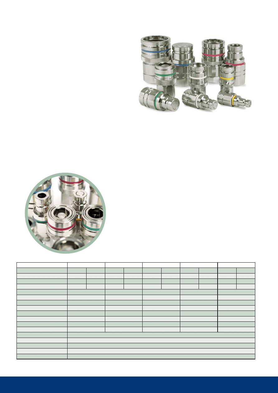
reliable, High-Flow Couplings for a wide range of
Fluid applications available in brass or stainless steel,
valved or valveless – up to 200 bar (2900 Psi)
4

5
CEJN Corporate Headquarter
CEJN ab
skövde, sweden
CEJN Sales Offices:
CEJN Norden ab
skövde, sweden
CEJN denmark aps
Esbjerg, denmark
CEJN Product gmbH
troisdorf, germany
CEJN France s.a.s
Paris, France
CEJN ag
Cham, switzerland
CEJN italy s.r.l.
milan, italy
CEJN ibérica s.l.
barcelona, spain
CEJN industrial Corporation
Chicago, usa
CEJN do brasil ltda
Curitiba, brazil
CEJN australia PtY limited
sydney, australia
CEJN japan Corporation
tokyo, Japan
CEJN Products Far East PtE ltd.
singapore City, singapore
CEJN Products Far East Co, ltd.
seoul, Korea
CEJN shanghai Fluid systems Co ltd
shanghai, China
CEJN Products india Pvt. ltd.
bangalore, india
ISO 9001 certified since 1995.
ISO 14001 certified since 2006.
The ability to quickly connect and discon nect fluid lines is the fundamental
role of quick couplings in fluid transfer applica tions. Fluid couplings must
also be leak free and withstand the media being transferred and the atmo-
spheric and operating condi tions to which they are subjected.
CEJN’s leadership in the design, develop ment, and manufacture of fluid couplings is evident in its
more than 45 years of success ful sales performance in numerous markets, each with its own specific
demands.
this leadership is the result of our steadfast commitment to taking every step possible to ensure CEJN
fluid couplings are synony mous with high quality and superior perfor mance characteristics.
CEJN’s fluid coupling lineup includes over 14 different series of products in both valved and valveless
designs for low- and medium-pressure applications.
offering maximum working pressures up to 200 bar (2900 Psi), CEJN offers just the right coupling
solution for virtually any fluid transfer application – from petrochemical, to pharmaceutical, to paint – in
which lines need to be connected and disconnected eas ily, safely, and reliably.
Incorporating an innovative, aerodynamic valve design, all CEJN fluid couplings offer superior flow
capacity with minimal pres sure drop.
they are available in stainless steel, nickel-, chrome-, or non-plated brass, depending on the series,
with seals in nitrile, viton®, or EPDM. Upon request, other coupling and seal material options are avail-
able to comply with specific performance objectives.
Because smooth fluid flow is a critical requirement in system operation, CEJN vig orously tests each
coupling it produces. All fluid couplings undergo extensive function ality and quality testing to ensure
defect-free performance where it is needed most – at the jobsite.
When you need smooth fluid flow and smooth equipment operation, call on
CEJN – your Quick Connect Specialist and reliable partner for high-quality
fluid couplings.
CEJN – Your Reliable
Partner for High-Quality
Fluid Couplings
6
7
141 221 225 321 322 324 326 411 412 414 416 417 604 606 704 706
•
•
•
• •
• •
• •
• • •
• • •
• •
• • • •
•
• • • • • • • • • • • •
• • • • • • • • •
• • •
1
1
1
1
1
1
1
1
1
1
1
1
1
2
1
2
2
2
2
2
2
2
1
2
2
2
1
2
1
2
1
2
2
2
2
2
2
2
2
2
2
2
2
2
2
2
2
2
2
2
2
2
• • • • • • • • • • • •
• • • •
• • • • • • • • • • • • • • •
•
• • • • • • • •
• • • •
•
•
• • • • • • • • • • •
•
• •
• • • • • • • • • •
• • • • • •
141 221 225 321 322 324 326 411 412 414 416 417 604 606 704 706
Series
Flow l/min.
0-5
5-10
10-20
20-30
30-50
50-75
75-100
100-150
150-200
200-250
250-300
Function
single shut-off
double shut-off
straight through
Sealing
Nitrile
viton
®
EP
Kalrez
®
Material
brass
Stainless Steel AISI 316
Style
Push-to-connect
two-hand operation
Dust Caps
included
as accessory
Working Pressure
8
10
20
35
70
200
Vacuum use
Yes
No
Series
overview
CEJN Fluid Couplings
1 = as standard, 2 = on request
8
141
10 141 1001
5.0 mm (3/16")
NBR
52.0
12.0
-
10 141 1201
G 1/8"
NBR
43.5
15.0
13
10 141 1251
G 1/8''
NBR
40.0
12.7
11
10 141 1451
NPT 1/8"
NBR
35.0
12.7
11
10 141 5000
3.0 mm (1/8'')
-
32.0
7.0
-
10 141 5001
5.0 mm (3/16'')
-
40.5
7.0
-
10 141 5201
G 1/8''
-
30.0
13.9
12
10 141 5451
NPT 1/8"
-
31.0
12.7
11
Nipples
(valvele
ss)
C
ou
pl
in
gs
(v
al
ve
d)
Hose connections
Female thread
male thread
Hose connection
Female thread
male thread
Part No.
Connection
seals
length dia.
Hex.
thread connections are listed according to iso standards. see Page 30 for additional information. all measurements are
in mm. Nbr=nitrile, FPm=viton
®
. Check with an authorized CEJN distributor for availability and prices.
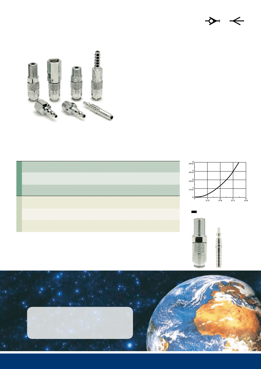
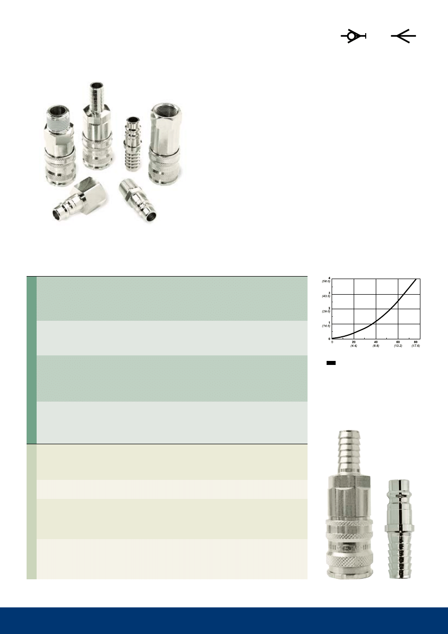
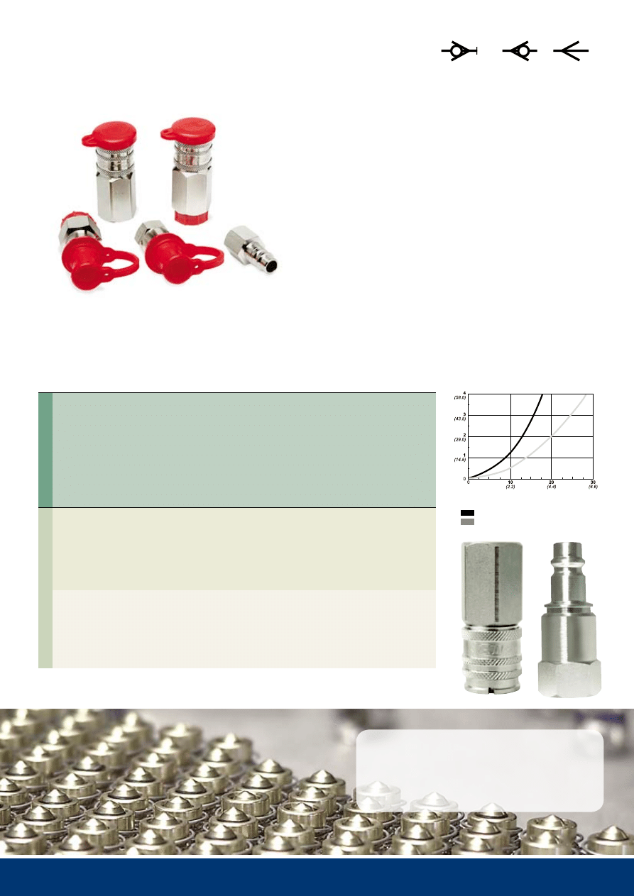
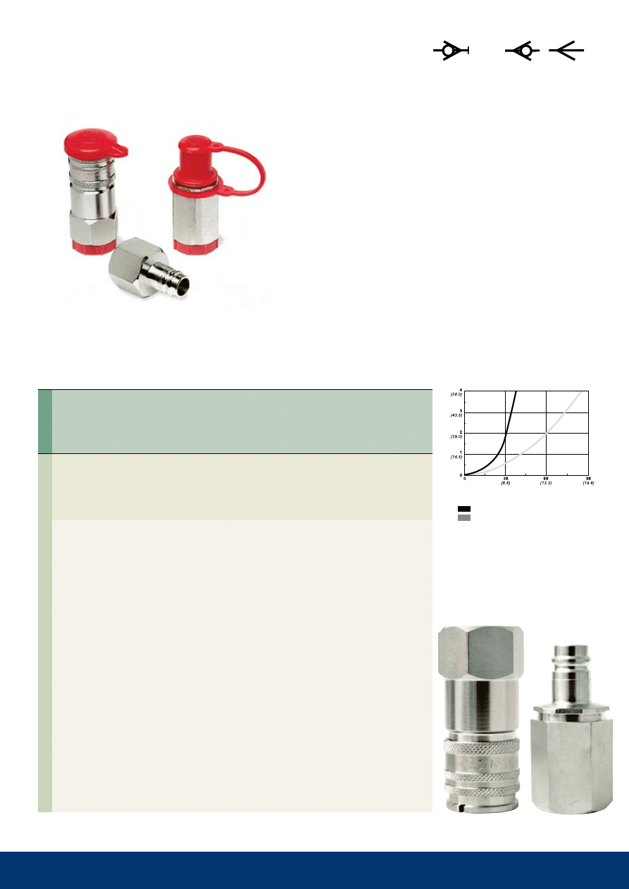
series 141
10 bar (145 PSI) – 3.5 l/min (0.8 GPM UK)
Technical Data
material:
Chrome-plated brass
Flow capacity at 4 bar
pressure drop:
3.5 l/min (0.77 GPM UK)
Max. working pressure: 10 bar (145 PSI)
Min. burst pressure:
40 bar (580 PSI)
temperature range:
-30°C to +100°C (-22°F to +212°F)
Nominal flow diameter: 2.5 mm (3/32")
Kv (Cv):
0.10 (0.12)
Information on CEJN's worldwide network of sales
companies, agents, and distributors is available at
www.cejn.com.
series 141 miniature couplings are specially designed for
dental and medical equipment applications. Among the
smallest couplings available today, series 141 features
valved couplings and valveless nipples that are easily
connected with one hand. viton
®
and EPdm seals are
available on request.
Pressure drop, bar (P
si
)
Flow, liters/min. (GPM -UK)
single shut-off
9
22..
10 220 1001
5.0 mm (3/16'')
NBR
47.4
19.6
17
10 220 1002
6.3 mm (1/4'')
NBR
47.4
19.6
17
10 220 1003
8.0 mm (5/16'')
NBR
50.4
19.6
17
10 220 1004
10.0 mm (3/8'')
NBR
50.4
19.6
17
10 220 1151
R 1/8''
NBR
39.4
19.6
17
10 220 1152
R 1/4''
NBR
42.9
19.6
17
10 220 1154
R 3/8''
NBR
41.4
19.6
17
10 220 1451
NPT 1/8"
NBR
37.9
19.6
17
10 220 1452
NPT 1/4"
NBR
42.4
19.6
17
10 220 1201
G 1/8''
NBR
38.9
19.6
17
10 220 1202
G 1/4''
NBR
42.9
19.6
17
10 220 1204
G 3/8''
NBR
44.4
23.1
20
10 220 1402
NPT 1/4"
NBR
42.9
19.6
17
10 225 1202
G 1/4''
NBR
42.9
19.6
17
10 221 5009*
5.0 mm (3/16'')
-
36.0
11.0
-
10 221 5002
6.3 mm (1/4'')
-
36.0
11.0
-
10 221 5152
R 1/4''
-
33.0
16.2
14
10 221 5251
G 1/8''
-
26.5
12.7
11
10 221 5452
NPT 1/4"
-
33.0
16.2
14
10 221 5201
G 1/8''
-
26.5
15.0
13
10 221 5202
G 1/4''
-
31.0
19.6
17
10 225 6202**
G 1/4''
NBR
31.0
19.6
17
** Valved nipples in Series 225 can only be used with Series 225 couplings.
Nipples
(valveless)
Couplings
(valved)
Hose connection
male thread
Female thread
Hose connection
(* nickel-plated)
male thread
Female thread
Female thread
(valved)
Part No.
Connection
seals
length dia.
Hex.
thread connections are listed according to iso standards. see Page 30 for additional information. all measurements are
in mm. Nbr=nitrile, FPm=viton
®
. Check with an authorized CEJN distributor for availability and prices.
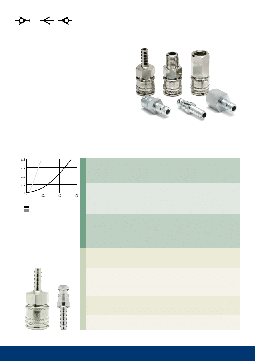
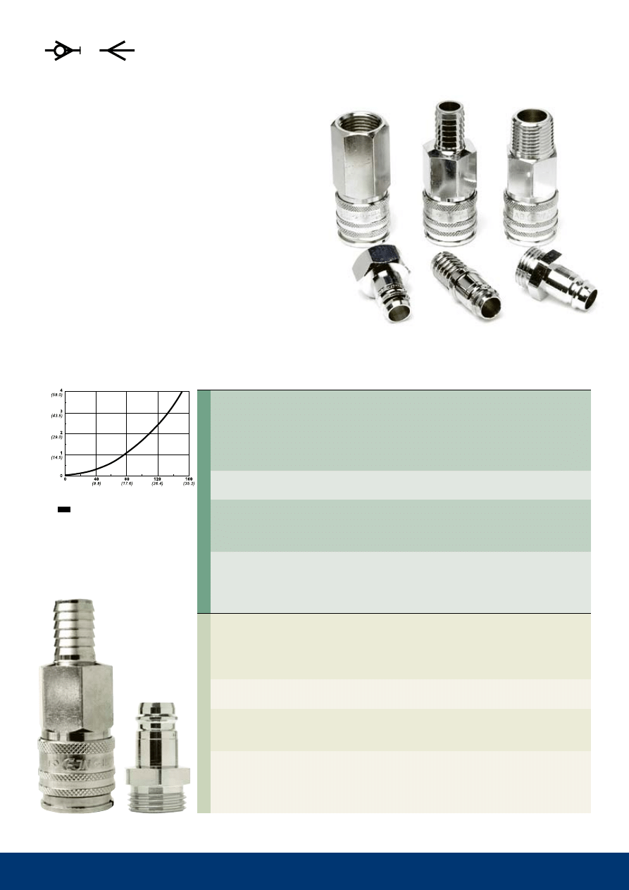
Series 220/221, 225
35 bar (508 PSI) – 26 l/min (5.72 GPM UK)
Technical Data
material: series 220 coupling: Nickel-plated brass
Series 225 coupling: Chrome-plated brass
Nipple: Chrome-plated brass
Flow capacity at 4 bar pressure drop:
Series 221 valveless nipple: 26 l/min (5.72 GPM UK)
Series 225 valved nipple: 8 l/min (1.76 GPM UK)
Max. working pressure: 35 bar (508 PSI)
min. burst pressure:
140 bar (2030 Psi)
temperature range Nbr: -30°C to +100°C (-22°F to +212°F)
Nominal flow diameter: Series 220 coupling: 5.0 mm (3/16")
Series 225 coupling: 3.0 mm (1/8")
Kv (Cv):
Series 220: 0.79 (0.92)
Series 225: 0.24 (0.28)
Requiring only one hand for operation, Series 220/221 and
Series 225 couplings are suitable for a variety of fluid applica-
tions, such as water inlet and return for injection molding lines.
Series 220/221 features valved couplings and valveless nip-
ples. Series 225 features both vavled couplings and valved nip-
ples. other sealing materials, such as viton
®
and EPdm, are
available on request. Straight-through couplings are also avail-
able on request.
Pressure drop, bar (P
si
)
Flow, liters/min. (GPM -UK)
225 Double shut-off
220/221 Single shut-off
10
321
10 321 1002
6.3 mm (1/4'')
NBR
67.0
23.4
19
10 321 1003
8.0 mm (5/16'')
NBR
69.5
23.4
19
10 321 1004
10.0 mm (3/8'')
NBR
70.0
23.4
19
10 321 1005
13.0 mm (1/2'')
NBR
68.0
23.4
19
10 321 1062
8x12 mm
NBR
68.0
23.4
20/19
10 321 1066
11x16 mm
NBR
68.0
27.7
24/24
10 321 1152
R 1/4''
NBR
63.0
23.4
20
10 321 1154
R 3/8''
NBR
61.0
23.4
20
10 321 1155
R 1/2''
NBR
55.5
25.4
22
10 321 1254
G 3/8''
NBR
56.5
23.4
20
10 321 1452
NPT 1/4''
NBR
62.0
23.4
20
10 321 1202
G 1/4''
NBR
60.0
23.4
20
10 321 1204
G 3/8''
NBR
60.0
23.4
20
10 321 1205
G 1/2''
NBR
59.5
28.9
25
10 321 1402
NPT 1/4''
NBR
59.0
23.4
20
10 321 5003
8.0 mm (5/16'')
-
44.5
13.0
-
10 321 5004
10.0 mm (3/8'')
-
44.5
14.0
-
10 321 5005
13.0 mm (1/2'')
-
44.5
17.0
-
10 321 5062
8x12 mm
-
46.3
21.9
19
10 321 5066
11x16 mm
-
53.3
27.7
24
10 321 5151
R 1/8''
-
35.0
15.0
13
10 321 5152
R 1/4''
-
38.5
16.2
14
10 321 5154
R 3/8''
-
40.5
19.6
17
10 321 5155
R 1/2''
-
47.0
25.4
22
10 321 5452
NPT 1/4''
-
37.5
16.2
14
10 321 5202
G 1/4''
-
36.0
19.6
17
10 321 5204
G 3/8''
-
37.5
21.3
20
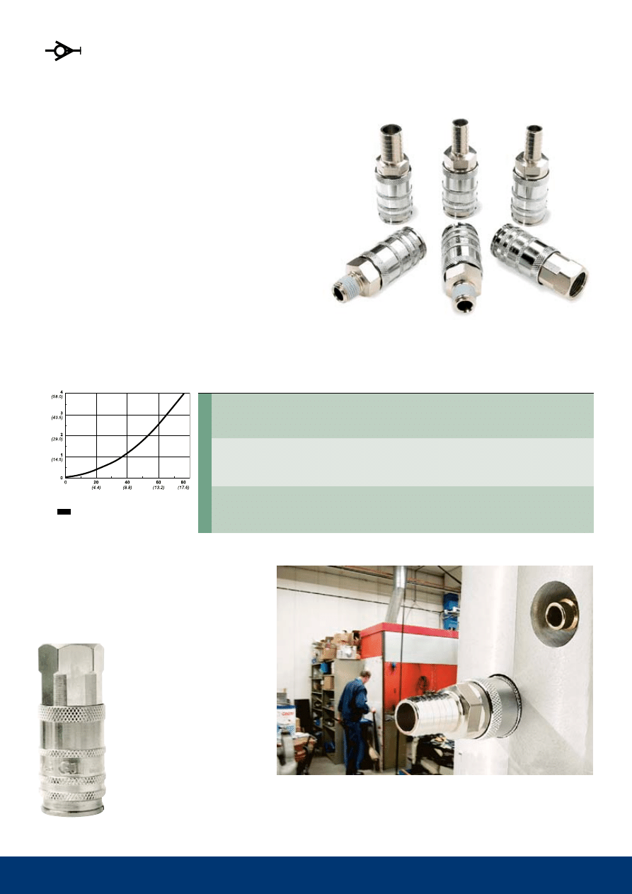
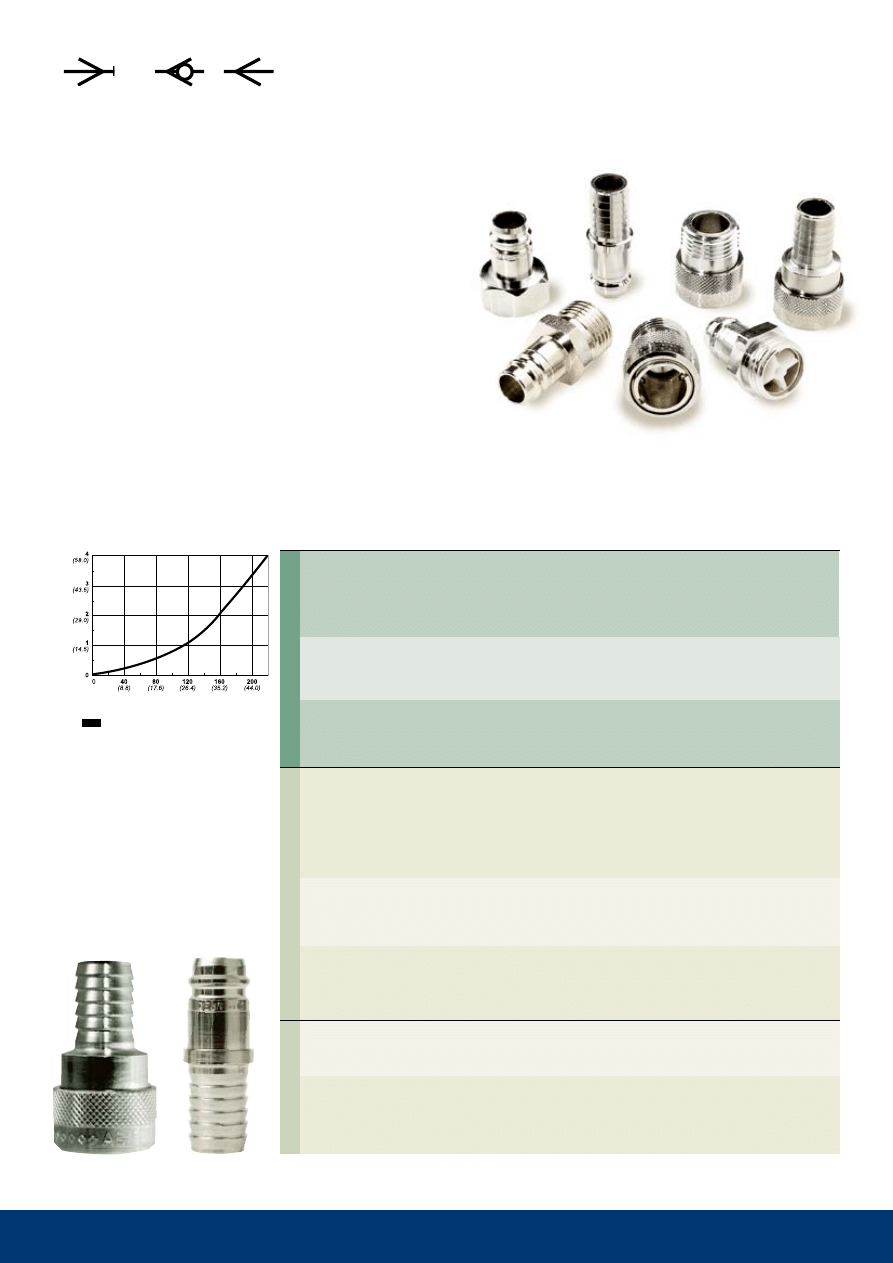
series 321
35 bar (508 PSI) – 78 l/min (17.1 GPM UK)
Technical Data
material:
Nickel-plated brass
Flow capacity at 4 bar
pressure drop:
78 l/min (17.16 GPM UK)
Max. working pressure:
35 bar (508 PSI)
min. burst pressure:
140 bar (2030 Psi)
temperature range Nbr: -20°C to +100°C (-4°F to +212°F)
Nominal flow diameter:
7.4 mm (9/32")
Kv (Cv):
2.34 (2.72)
Nipples
(valveless)
Couplings
(valved)
Hose connection
stream-line connection
male thread
Female thread
Hose connection
stream-line Connection
male thread
Female thread
Part No.
Connection
seals
length dia.
Hex.
thread connections are listed according to iso standards. see Page 30 for additional information. all measurements are
in mm. Nbr=nitrile, FPm=viton
®
. Check with an authorized CEJN distributor for availability and prices.
Pressure drop, bar (P
si
)
Flow, liters/min. (GPM -UK)
Featuring vavled couplings and valveless nipples, series 321
has superior flow capacity. series 321 is suitable for a variety
of fluid applications, such as water inlet and return for injection
molding lines. a large range of connections is available in the
series that requires only one hand for operation. Other sealing
materials, such as viton
®
and EPDM, are availabe on request.
single shut-off
11
321
10 321 1044
8.0 mm (5/16'')
FPM
67.5
23.4
19
10 321 1045
13.0 mm (1/2'')
FPM
65.5
23.4
19
10 321 1294
G 3/8''
FPM
54.0
23.4
20
10 321 1244
G 3/8''
FPM
57.5
23.4
20
series 321 long
35 bar (508 PSI) – 78 l/min (17.1 GPM UK)
Technical Data
material:
Nickel-plated brass
Flow capacity at 4 bar
pressure drop:
78 l/min (17.1 GPM UK)
Max. working pressure:
35 bar (508 PSI)
min. burst pressure:
140 bar (2030 Psi)
Temperature range FPM: -15°C to +100°C (+5°F to +212°F)
Nominal flow diameter:
7.4 mm (9/32")
Kv (Cv):
2.34 (2.72)
Couplings
(valved
)
Hose connection
male thread
Female thread
Part No.
Connection
seals
length dia.
Hex.
thread connections are listed according to iso standards. see Page 30 for additional information. all measurements are
in mm. Nbr=nitrile, FPm=viton
®
. Check with an authorized CEJN distributor for availability and prices.
Pressure drop, bar (P
si
)
Flow, liters/min. (GPM -UK)
series 321 with a long locking sleeve is specially designed for
applications with built-in nipples, such as water inlet and return
for injection molding lines (see picture). Featuring valved cou-
plings and valveless nipples, this version has the same features
as standard series 321 couplings, including superior flow
capacity. other connections and sealing material are available
on request.
single shut-off
12
322
10 322 0252
G 1/4''
NBR
46.7
23.4
20
10 322 0254 * G 3/8''
NBR
48.2
23.4
20
10 322 0255 * G 1/2''
NBR
50.2
25.4
22
10 322 0297 * ** G 3/8''
FPM
48.2
23.4
20
10 322 1252
G 1/4''
FPM
55.3
23.4
20
10 322 1202
G 1/4''
NBR
56.8
23.4
20
10 322 1204
G 3/8''
NBR
56.8
25.4
22
10 322 1404
NPT 3/8''
NBR
55.8
25.4
22
10 322 0202
G 1/4''
NBR
48.7
23.4
20
10 322 0212
G 1/4''
FPM
48.7
23.4
20
10 322 0204
G 3/8''
NBR
49.7
25.4
22
10 322 0214
G 3/8''
FPM
49.7
25.4
22
10 322 0402
NPT 1/4''
NBR
55.7
23.4
20
10 322 5162
R 1/4''
-
38.5
16.2
14
10 322 5164
R 3/8''
-
40.5
19.6
17
10 322 5252
G 1/4''
-
35.5
16.2
14
10 322 5264 * G 3/8''
-
37.5
19.6
17
10 322 5212
G 1/4''
-
36.0
19.6
17
10 322 5214
G 3/8''
-
37.5
23.1
20
10 322 5202
G 1/4''
-
36.5
19.6
17
10 322 5204
G 3/8''
-
38.0
23.1
20
Nipples
(valveless)
Couplings
male thread
(valveless)
(* with 60° sealing cone
** ratchet sleeve in steel)
male thread
(valved)
Female thread
(valved)
Female thread
(valveless)
male thread
(Steel – hardened
and yellow zinc-plated
)
male thread
(Steel – hardened and
chemical nickel-plated
* with 60° sealing cone)
Female thread
(Steel – hardened and
yellow zinc-plated)
Female thread
(Steel – hardened and
chemical nickel-plated)
Part No.
Connection
seals
length dia.
Hex.
thread connections are listed according to iso standards. see Page 30 for additional information. all measurements are
in mm. Nbr=nitrile, FPm=viton
®
. Check with an authorized CEJN distributor for availability and prices.
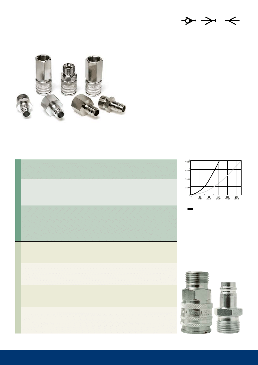
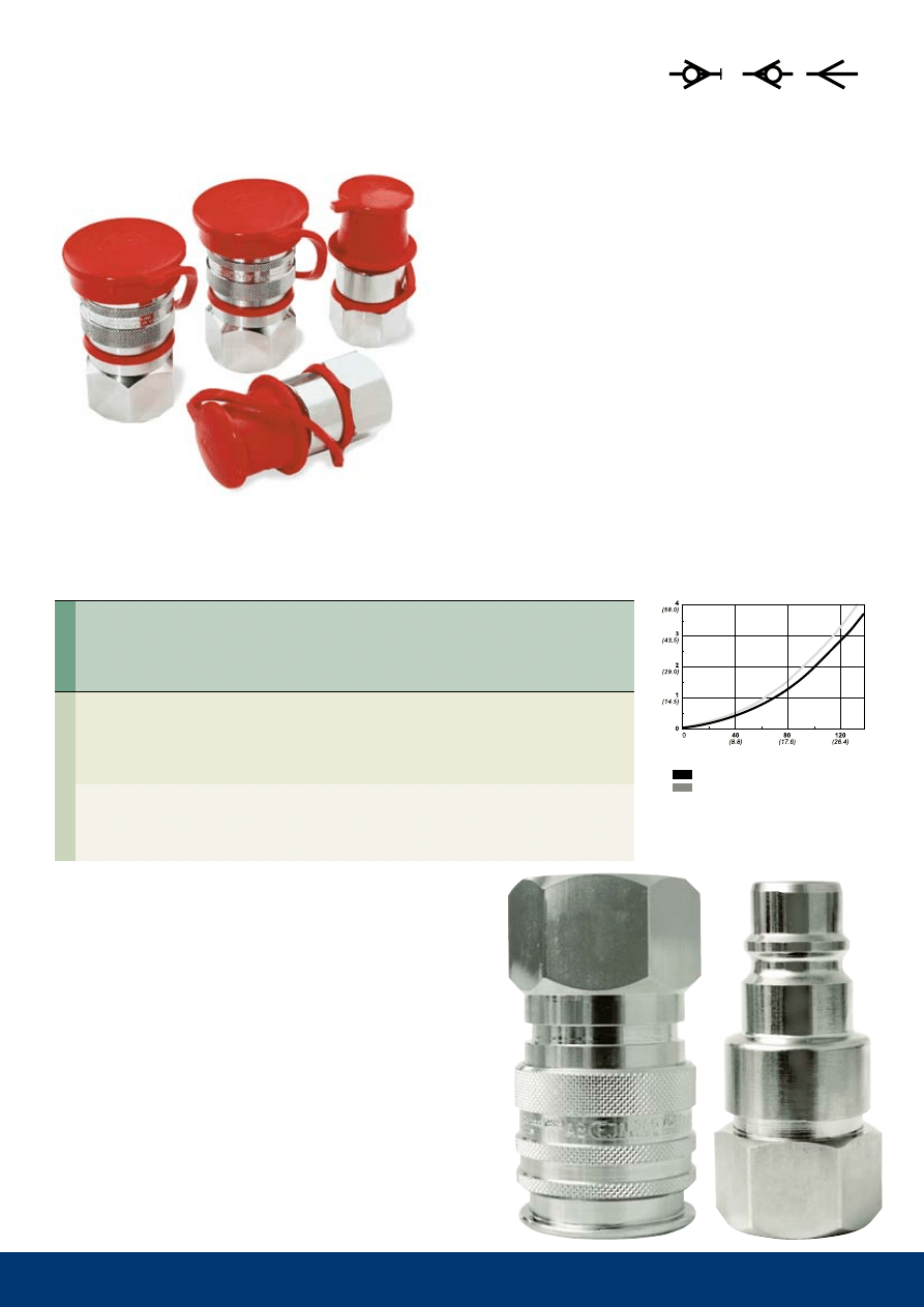
series 322
200 bar (2900 PSI) - 90 l/min (19.8 GPM UK)
Technical Data
Material: Coupling
Brass/steel, nickle-plated
Nipple
Hardened steel, chemical nickel-
plated/zinc-plated
Flow capacity at
4 bar pressure drop:
90 l/min (19.8 GPM UK)
max. working pressure: 200 bar (2900 Psi)
Min. burst pressure:
600 bar (8700 PSI)
temperature range Nbr: -30°C to +100°C (-22°F to +212°F)
Nominal flow diameter:
7.4 mm (9/32")
Kv (Cv):
2.70 (3.14)
series 322 offers a high working pressure rating and high-flow
capacity, making it ideal for high-pressure water applications,
such as high-pressure cleaning lines. available with valved or
valveless couplings, the series requires only one hand for oper-
ation – just one of the reasons why this original CEJN series
continues to be requested. Other connections and sealing
materials are available on requeast.
Pressure drop, bar (P
si
)
Flow, liters/min. (GPM -UK)
single shut-off
13
324
10 324 1002
6.0 mm (1/4'')
NBR
66.3
23.4
20
10 324 1003
8.0 mm (5/16'')
NBR
68.3
23.4
20
10 324 1004
10.0 mm (3/8'')
NBR
67.3
23.4
20
10 324 1005
13.0 mm (1/2'')
NBR
66.3
23.4
20
10 324 1152
R 1/4''
NBR
59.3
23.4
20
10 324 1154
R 3/8''
NBR
58.3
23.4
20
10 324 1155
R 1/2''
NBR
51.8
25.4
22
10 324 1202
G 1/4''
NBR
56.3
23.4
20
10 324 1204
G 3/8''
NBR
56.3
25.4
22
10 324 1205
G 1/2''
NBR
60.3
28.9
25
10 324 1212
G 1/4''
FPM
56.3
23.4
20
10 324 1222
G 1/4''
EPDM
56.3
23.4
20
10 324 1402
NPT 1/4''
NBR
56.3
23.4
20
10 324 6202
G 1/4''
NBR
52.1
23.1
20
10 324 6212
G 1/4''
FPM
52.1
23.1
20
10 324 6222
G 1/4''
EPDM 52.1
23.1
20
10 324 6402
NPT 1/4''
NBR
52.1
23.1
20
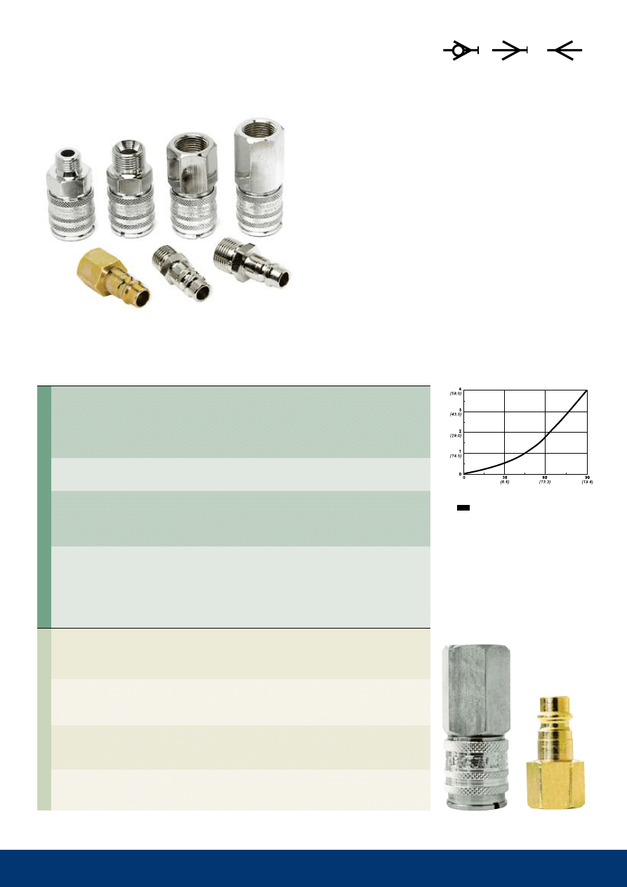
series 324
35 bar (508 PSI) - 42 l/min (9.2 GPM UK)
Technical Data
material:
Nickle-plated brass
Flow capacity at 4 bar pressure drop:
Series 324 nipple:
42 l/min (9.2 GPM UK)
Series 321 nipple:
53 l/min (11.6 GPM UK)
Max. working pressure: 35 bar (508 PSI)
min. burst pressure:
140 bar (2030 Psi)
temperature range Nbr: -30°C to +100°C (-22°F to +212°F)
Nominal flow diameter:
6.2 mm (1/4")
Kv (Cv): 324 nipple
1.26 (1.46)
321 nipple
1.59 (1.85)
Nippl
es
(valved)
Couplings
(valved)
Hose connection
male thread
Female thread
Female thread
Part No.
Connection
seals
length dia.
Hex.
thread connections are listed according to iso standards. see Page 30 for additional information. all measurements are
in mm. Nbr=nitrile, FPm=viton
®
. Check with an authorized CEJN distributor for availability and prices.
series 324 offers a two-way shutoff and is connectable with the
valveless nipple in series 321. designed with small external
dimensions, it is suitable for a variety of fluid applications, such
as water inlet and return for injection molding lines. only one
hand is required to connect this original CEJN product offering.
dust caps are included. other sealing materials and connec-
tions are available on request.
Pressure drop, bar (P
si
)
Flow, liters/min. (GPM -UK)
series 321 nipple
series 324 nipple
14
326
10 326 1202
G 1/4''
NBR
51.3
24.3
21
10 326 1204
G 3/8'' *
NBR
54.8
25.4
22
10 326 1212
G 1/4''
FPM
51.3
24.3
21
10 326 1214
G 3/8'' *
FPM
54.8
25.4
22
10 326 6202
G 1/4''
NBR
52.1
22.0
19
10 326 6204
G 3/8''
NBR
54.1
25.4
22
10 326 6212
G 1/4''
FPM
52.1
22.0
19
10 326 6214
G 3/8''
FPM
54.1
25.4
22
10 326 5232
G 1/4''
-
37.5
19.6
17
Nipples
Couplings
(valved)
Female thread
(* 9 mm)
Female thread
(valved)
Female thread
(valveless)
Part No.
Connection
seals
length
dia.
Hex.
thread connections are listed according to iso standards. see Page 30 for additional information. all measurements are
in mm. Nbr=nitrile, FPm=viton
®
. Check with an authorized CEJN distributor for availability and prices.
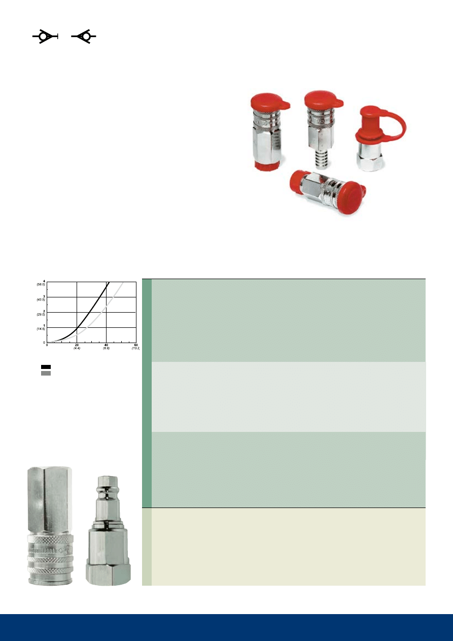
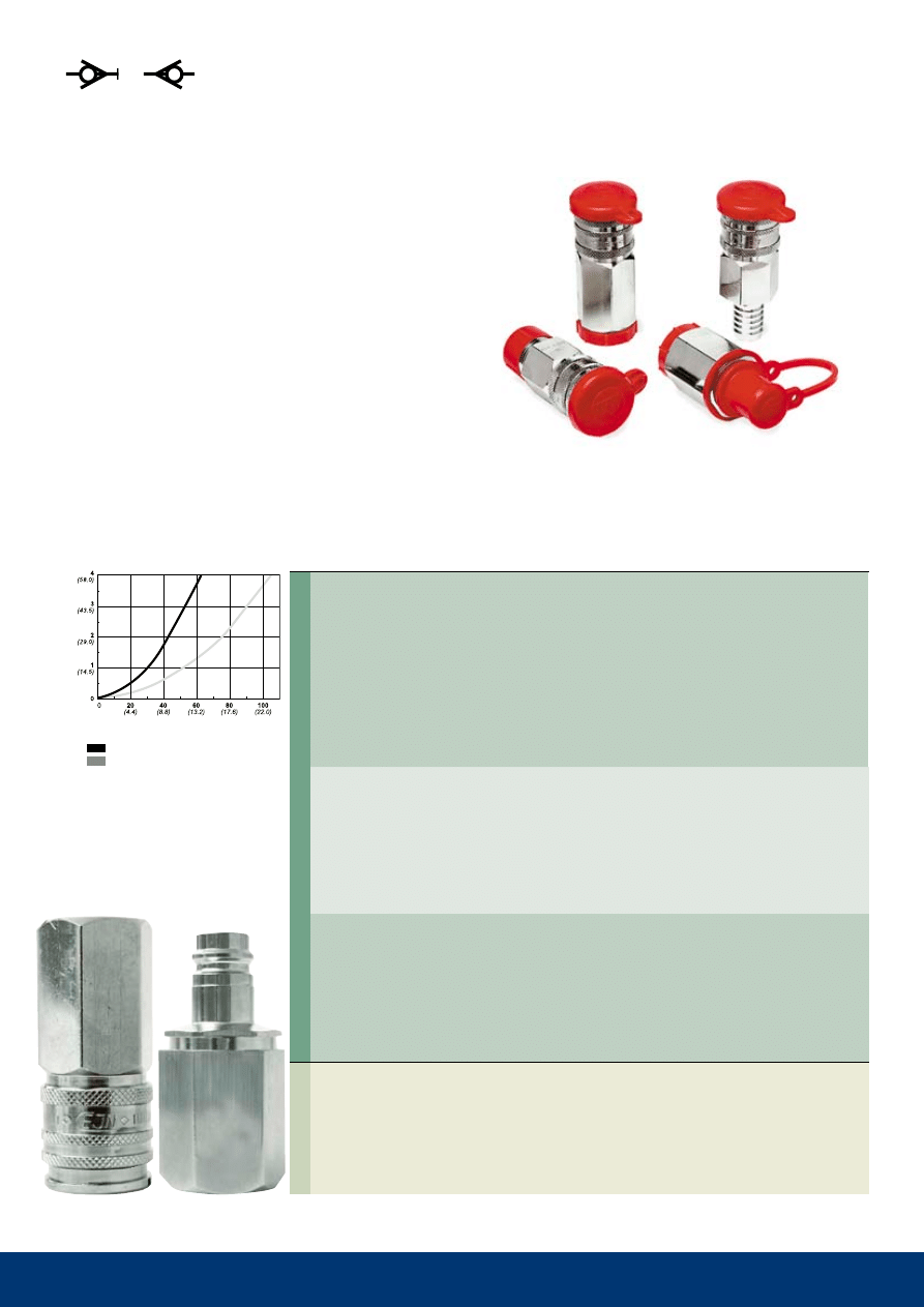
Series 326
70 bar (1015 PSI) - 18 l/min (3.9 GPM UK)
Technical Data
Material:
Stainless steel, AISI 316
Flow capacity at 4 bar pressure drop:
Valved nipple:
18 l/min (3.96 GPM UK)
Valveless nipple:
28 l/min (6.16 GPM UK)
Max. working pressure: 70 bar (1015 PSI)
Min. burst pressure:
280 bar (4060 PSI)
Temperature range FPM: -15°C to +100°C (+5°F to +212°F)
Nominal flow diameter:
6.2 mm (1/4")
Kv (Cv): valved
0.54 (0.63)
valveless
0.84 (0.98)
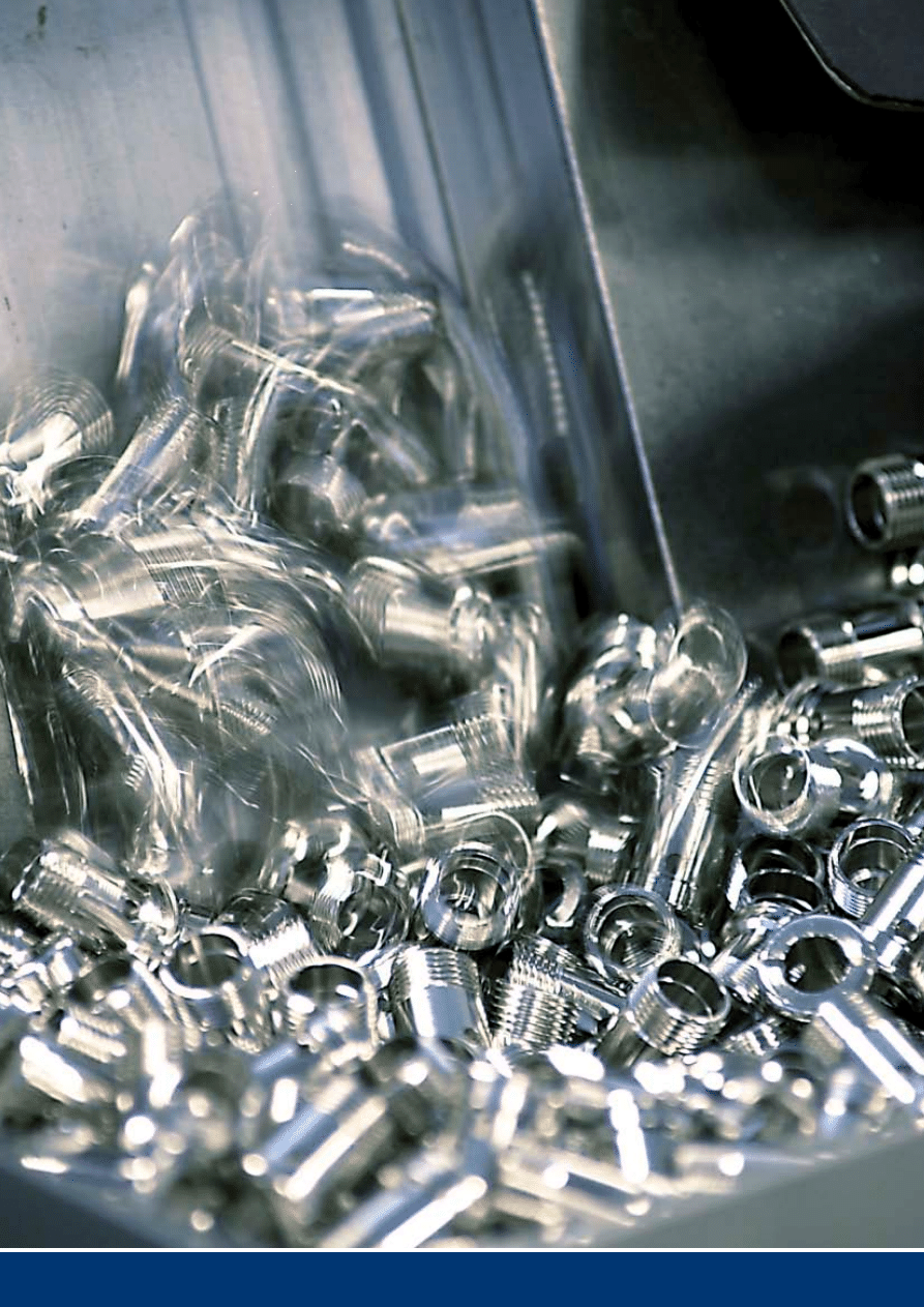
CEJN uses only the finest raw materials
to produce its high-quality products.
Compatible with aggressive medias, Series 326 stands up to
food, offshore, and steam applications. one- and two-way shut-
off styles are included in the series that requires only one hand
for operation. dust caps are included as standard. EPdm seals
are available on request.
Pressure drop, bar (P
si
)
Flow, liters/min. (GPM -UK)
single shut-off
double shut-off
15
411
10 411 1003
8.0 mm (5/16")
NBR
73.8
27.7
24
10 411 1004
10.0 mm (3/8")
NBR
72.8
27.7
24
10 411 1005
13.0 mm (1/2")
NBR
71.3
27.7
24
10 411 1006
16.0 mm (5/8")
NBR
72.3
27.7
24
10 411 1007
19.0 mm (3/4")
NBR
70.3
27.7
24
10 411 1066
11x16 mm
NBR
78.6
27.7
24
10 411 1154
R 3/8"
NBR
63.8
27.7
24
10 411 1155
R 1/2"
NBR
66.3
27.7
24
10 411 1157
R 3/4"
NBR
59.8
31.2
27
10 411 1204
G 3/8"
NBR
58.3
27.7
24
10 411 1205
G 1/2"
NBR
63.3
28.9
25
10 411 1207
G 3/4"
NBR
60.3
37.0
32
10 411 5004
10.0 mm (3/8")
-
46.5
17.0
-
10 411 5005
13.0 mm (1/2")
-
46.0
17.0
-
10 411 5006
16.0 mm (5/8")
-
48.5
21.0
-
10 411 5007
19.0 mm (3/4")
-
49.0
25.0
-
10 411 5066
11x16 mm
-
540.0 27.7
24
10 411 5255
G 1/2"
-
37.0
25.4
22
10 411 5257
G 3/4"
-
39.5
31.2
27
10 411 5204
G 3/8"
-
34.5
24.2
21
10 411 5205
G 1/2"
-
34.5
27.7
24
10 411 5207
G 3/4"
-
35.0
34.6
30
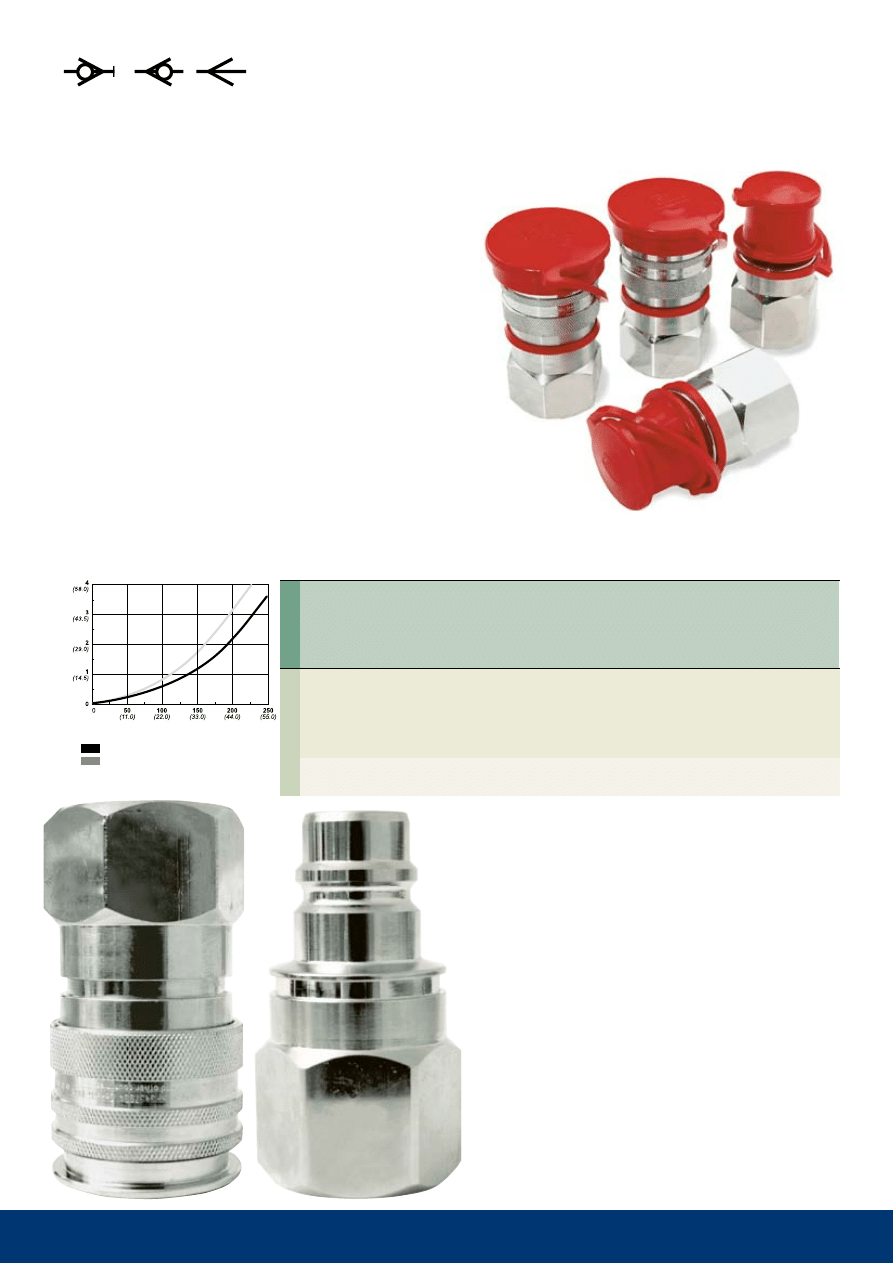
series 411
35 bar (508 PSI) - 156 l/min (34.3 GPM UK)
Technical Data
material: Coupling- Nickle-plated brass
Nipple- Chrome-plated brass
Flow capacity at 4 bar
pressure drop:
156 l/min (34.32 GPM UK)
Max. working pressure: 35 bar (508 PSI)
min. burst pressure:
140 bar (2030 Psi)
temperature range Nbr: -30°C to +100°C (-22°F to +212°F)
Nominal flow diameter:
10.4 mm (13/32")
Kv (Cv):
4.68 (5.44)
Nipples
(valveless)
Couplings
(valved)
Hose connection
stream-line Connection
male thread
Female thread
Hose connection
stream-line Connection
male thread
Female thread
Part No.
Connection
seals
length dia.
Hex.
thread connections are listed according to iso standards. see Page 30 for additional information. all measurements are
in mm. Nbr=nitril,FPm=viton
®
. Check with an authorized CEJN distributor for availability and prices.
series 411 features valved couplings and valveless nipples.
Requiring only one hand for operation, the series is suitable for
a variety of fluid applications, such as water inlet and return for
injection molding lines.
Pressure drop, bar (P
si
)
Flow, liters/min. (GPM -UK)
single shut-off
16
412
10 412 0255 * G 1/2''
NBR
50.7
27.7
24
10 412 0455
NPT 1/2"
NBR
65.3
27.7
24
10 412 1205
G 1/2''
NBR
63.3
28.9
25
10 412 0205
G 1/2''
NBR
63.3
28.9
25
10 412 0405
NPT 1/2''
NBR
63.3
28.9
25
10 412 5265 * G 1/2''
-
42.3
25.4
22
10 412 5205
G 1/2''
-
44.0
31.2
27
10 410 5154
R 3/8''
-
42.5
19.6
17
10 410 5155
R 1/2''
-
48.0
25.4
22
10 410 5204
G 3/8''
-
39.0
23.1
20
10 410 5205
G 1/2''
-
44.0
31.2
27
Nipples
(valveless)
Couplings
male thread
(valveless
* with 60° sealing cone)
Female thread
(valved)
Female thread
(valveless)
male thread
(Steel – hardened and
chemical nickel-plated
* with 60° sealing cone
)
Female thread
(Steel – hardened and
chemical nickel-plated )
male thread
(Steel – hardened and
zinc-plated)
Female thread
(Steel – hardened and
zinc-plated)
Part No.
Connection
seals
length dia.
Hex.
thread connections are listed according to iso standards. see Page 30 for additional information. all measurements are
in mm. Nbr = nitrile, FPm = viton
®
. Check with an authorized CEJN distributor for availability and prices.
series 412
200 bar (2900 PSI) - 167 l/min (36.7 GPM UK)
Technical Data
Material: Coupling–Nickle-plated brass/steel
Nipple–Hardened steel, chemical nickel-plated/zinc-plated
Flow capacity at
4 bar pressure drop:
167 l/min (36.74 GPM UK)
max. working pressure: 200 bar (2900 Psi)
Min. burst pressure:
600 bar (8700 PSI)
temperature range Nbr: -30°C to +100°C (-22°F to +212°F)
Nominal flow diameter:
10.4 mm (13/32")
Kv (Cv):
5.01 (5.83)
the 200 bar working pressure of series 412 makes this prod-
uct line suitable for high-pressure water applications and high-
pressure cleaning. included in the series are valved and valve-
less couplings and valveless nipples. Only one hand is required
for operation. Other sealing materials are available on request.
Pressure drop, bar (P
si
)
Flow, liters/min. (GPM -UK)
single shut-off
17
414
10 414 1004
10.0 mm (3/8'')
NBR
72.8
27.7
24
10 414 1005
13.0 mm (1/2'')
NBR
71.3
27.7
24
10 414 1006
16.0 mm (5/8'')
NBR
71.3
27.7
24
10 414 1007
19.0 mm (3/4'')
NBR
70.3
27.7
24
10 414 1154
R 3/8''
NBR
63.8
27.7
24
10 414 1155
R 1/2''
NBR
66.3
27.7
24
10 414 1157
R 3/4''
NBR
59.8
31.2
27
10 414 1204
G 3/8''
NBR
58.3
27.7
24
10 414 1205
G 1/2''
NBR
63.3
28.9
25
10 414 1207
G 3/4''
NBR
60.3
37.0
32
10 414 1405
NPT 1/2''
NBR
63.3
28.9
25
10 414 6205
G 1/2''
NBR
59.4
31.2
27
10 414 6405
NPT 1/2''
NBR
59.4
31.2
27
series 414
35 bar (508 PSI) - 71 l/min (15.6 GPM UK )
Technical Data
material:
Chrome-plated brass
Flow capacity at 4 bar pressure drop:
Series 414 nipple:
71 l/min (15.6 GPM UK)
Series 411 nipple:
104 l/min (22.9 GPM UK)
Max. working pressure: 35 bar (508 PSI)
min. burst pressure:
140 bar (2030 Psi)
temperature range Nbr: -30°C to +100°C (-22°F to +212°F)
Nominal flow diameter:
8.9 mm (11/32")
Kv (Cv): double valved 2.13 (2.48)
411 nipple
3.12 (3.63)
Nipples
(valved)
Couplings
(valved)
Hose connection
male thread
Female thread
Female thread
Part No.
Connection
seals
length dia.
Hex.
thread connections are listed according to iso standards. see Page 30 for additional information. all measurements are
in mm. Nbr = nitrile, FPm = viton
®
. Check with an authorized CEJN distributor for availability and prices.
series 414 includes a two-way shutoff and is connectable with
Series 411 valveless nipples. Requiring only one hand for
operation, series 414 couplings are suitable for a variety of
fluid applications, such as water inlet and return for injection
molding lines. dust caps are included as standard. viton
®
and
EPDM sealings are available on request.
Pressure drop, bar (P
si
)
Flow, liters/min. (GPM -UK)
series 411 nipple
series 414 nipple
18
416
10 416 1205
G 1/2''
NBR
63.3
31.2
27
10 416 1215
G 1/2''
FPM
63.3
31.2
27
10 416 6205
G 1/2''
NBR
60.5
31.2
27
10 416 6215
G 1/2''
FPM
60.5
31.2
27
10 416 5205
G 1/2''
-
45.0
31.2
27
Nipples
Couplings
Female thread
(valved)
Female thread
(valved)
Female thread
(valveless)
Part No.
Connection
seals
length dia. Hex.
thread connections are listed according to iso standards. see Page 30 for additional information. all measurements are
in mm. Nbr = nitril, FPm = viton
®
. Check with an authorized CEJN distributor for availability and prices.
Series 416
35 bar (508 PSI)
Technical Data
Material:
Stainless steel, AISI 316
Flow capacity at 4 bar pressure drop:
Valved nipple:
45 l/min (9.9 GPM UK)
Valveless nipple:
85 l/min (18.7 GPM UK)
Max. working pressure: 35 bar (508 PSI)
min. burst pressure:
140 bar (2030 Psi)
Temperature range FPM: -15°C to +205°C (+5°F to +401°F)
Nominal flow diameter: 8.9 mm (11/32")
Kv (Cv): 1.35 (1.57) valved, 2.55 (2.96) valveless nipple
Compatible with aggressive medias, Series 416 stands up to
food, offshore, and steam applications. one- and two-way shutoff
styles are included in the series that requires only one hand for
operation. dust caps are included as standard. EPdm and
Kalrez
®
seals are available on request.
Pressure drop, bar (P
si
)
Flow, liters/min. (GPM -UK)
Flow, gPm
single shut-off
double shut-off
19
417
10 417 0005
13.0 mm (1/2")
NBR
45.0
24.0
-
10 417 0006
16.0 mm (5/8")
NBR
46.5
24.0
-
10 417 0007
19.0 mm (3/4")
NBR
47.0
24.0
-
10 417 0255
G 1/2"
NBR
30.0
24.0
-
10 417 0257
G 3/4"
NBR
29.0
24.0
-
10 417 0205
G 1/2"
NBR
32.5
27.7
24
10 417 0207
G 3/4"
NBR
34.0
32.0
30
10 411 5004
10.0 mm (3/8")
-
46.5
17.0
-
10 411 5005
13.0 mm (1/2")
-
46.0
17.0
-
10 411 5006
16.0 mm (5/8")
-
48.5
21.0
-
10 411 5007
19.0 mm (3/4")
-
49.0
25.0
-
10 411 5255
G 1/2"
-
37.0
25.4
22
10 411 5257
G 3/4"
-
39.5
31.2
27
10 411 5204
G 3/8"
-
34.5
24.3
21
10 411 5205
G 1/2"
-
34.5
27.7
24
10 411 5207
G 3/4"
-
35.0
34.6
30
10 411 7005
13.0 mm (1/2")
EPDM
64.0
23.0
-
10 411 7255
G 1/2"
EPDM
37.0
25.4
22
Series 417
20 bar (290 PSI) - 226 l/min (49.7 GPM UK)
Technical Data
material:
Chrome-plated brass
Flow capacity at 4 bar
pressure drop:
226 l/min (49.72 GPM UK)
max. working pressure: 20 bar (290 Psi)
Min. burst pressure:
80 bar (1160 PSI)
temperature range:
-30°C to +100°C (-22°F to +212°F)
Nominal flow diameter: 10.5 mm (13/32")
Kv (Cv):
6.78 (7.88)
Nipples
(valved)
Nipples
(valveless)
Couplings
(valveless)
Hose connection
male thread
Female thread
Hose connection
male thread
Female thread
Hose connection
male thread
Part No.
Connection
seals
length dia. Hex.
thread connections are listed according to iso standards. see Page 30 for additional information. all measurements are
in mm. Nbr = nitril, FPm = viton
®
. Check with an authorized CEJN distributor for availability and prices.
The straight-through, valveless design of Series 417 couplings
makes them ideal for garden and other low-pressure applica-
tions in which there is no need for valved-style couplings. two
hands are needed to connect Series 417 couplings, which are
connectable to series 411 nippels.
Pressure drop, bar (P
si
)
Flow, liters/min. (GPM -UK)
straight thru
20
60..
10 604 1201
G 3/4''
NBR
83.0
47.3
41
10 604 1211
G 3/4''
FPM
83.0
47.3
41
10 604 1401
NPT 3/4''
NBR
83.0
47.3
41
10 604 1411
NPT 3/4''
FPM
83.0
47.3
41
10 606 1211
G 3/4''
FPM
83.0
47.3
41
10 604 6201
G 3/4''
NBR
81.5
41.6
36
10 604 6211
G 3/4''
FPM
81.5
41.6
36
10 604 6401
NPT 3/4''
NBR
81.5
41.6
36
10 604 6411
NPT 3/4''
FPM
81.5
41.6
36
10 606 6211
G 3/4''
FPM
81.5
41.6
36
10 604 5201
G 3/4''
-
81.5
41.6
36
10 604 5401
NPT 3/4''
-
81.5
41.6
36
10 606 5201
G 3/4''
-
81.5
41.6
36
10 606 5401
NPT 3/4''
-
81.5
41.6
36
Nipples
Couplings
Female thread
(valved)
Female thread
(valved)
Female thread
(valveless)
Part No.
Connection
seals
length dia.
Hex.
thread connections are listed according to iso standards. see Page 30 for additional
information. all measurements are in mm. Nbr=nitrile, FPm=viton
®
. Check with an
authorized CEJN distributor for availability and prices.
One- and two-way shutoff styles are included in Series 604 and
Series 606 couplings that require only one hand for operation.
Series 604 is suitable for a variety of fluid applications, such as
water inlet and return. Series 606 stands up to food, offshore,
and steam applications. dust caps are included as standard.
Series 604, 606
35 bar (508 PSI)
Technical Data Series 604
material:
Chrome-plated brass
Flow capacity at 4 bar pressure drop:
valved nipple:
140 l/min (30.8 GPM UK)
valveless nipple:
210 l/min (46.2 GPM UK)
Max. working pressure: 35 bar (508 PSI)
min. burst pressure:
140 bar (2030 Psi)
temperature range Nbr: -30°C to +100°C (-22°F to +212°F)
Nominal flow diameter:
14.5 mm (9/16")
Kv (Cv): valved
4.20 (4.88)
valveless nipple 6.30 (7.33)
Pressure drop, bar (P
si
)
Flow, liters/min. (GPM -UK)
Technical Data Series 606
Material:
Stainless steel, AISI 316
Flow capacity at 4 bar pressure drop:
valved nipple:
134 l/min (29.4 GPM UK)
valveless nipple:
207 l/min (45.5 GPM UK)
Max. working pressure: 35 bar (508 PSI)
min. burst pressure:
140 bar (2030 Psi)
Temperature range: FPM -15°C to +205°C (+5°F to +401°F)
Nominal flow diameter:
14.5 mm (9/16")
Kv (Cv): valved
4.02 (4.67)
valveless nipple 6.21 (7.22)
606 Double shut-off
604 Double shut-off
21
70..
10 704 1203
G 1''
NBR
94.0
53.1
46
10 704 1213
G 1''
FPM
94.0
53.1
46
10 704 1403
NPT 1''
NBR
94.0
53.1
46
10 704 1413
NPT 1''
FPM
94.0
53.1
46
10 706 1213
G 1''
FPM
94.0
53.0
46
10 704 6203
G 1''
NBR
91.5
53.1
46
10 704 6213
G 1''
FPM
91.5
53.1
46
10 704 6403
NPT 1''
NBR
91.5
53.1
46
10 704 6413
NPT 1''
FPM
91.5
53.1
46
10 706 6213
G 1''
FPM
91.5
53.1
46
10 704 5203
G 1''
-
91.5
53.1
46
10 706 5203
G 1''
-
91.5
53.1
46
Requiring only one hand for operation, Series 704 and Series
706 couplings feature a two-way shutoff. A valveless nipple style
is available upon request. Series 704 is suitable for water inlet
and return for injection molding lines. Series 706 stands up to
food, offshore, and steam applications. dust caps are included as
standard.
Series 704, 706
35 bar (508 PSI)
Part No.
Connection
seals
length dia.
Hex.
thread connections are listed according to iso standards. see Page 30 for
additional information. all measurements are in mm. Nbr=nitrile, FPm=viton
®
.
Check with an authorized CEJN distributor for availability and prices.
Nipples
Couplings
Female thread
(valved)
Female thread
(valved)
Female thread
(valveless)
Technical Data Series 704
material:
Chrome-plated brass
Flow capacity at
4 bar pressure drop:
271 l/min (59.62 GPM UK)
Max. working pressure: 35 bar (508 PSI)
min. burst pressure:
140 bar (2030 Psi)
temperature range Nbr: -30°C to +100°C (-22°F to +212°F)
Nominal flow diameter:
19.0 mm (3/4")
Kv (Cv):
8.13 (9.45)
Pressure drop, bar (P
si
)
Flow, liters/min. (GPM -UK)
Technical Data Series 706
Material:
Stainless steel, AISI 316
Flow capacity at
4 bar pressure drop:
227 l/min (49.94 GPM UK)
Max. working pressure: 35 bar (508 PSI)
min. burst pressure:
140 bar (2030 Psi)
Temperature range: FPM -15°C to +205°C (+5°F to +401°F)
Nominal flow diameter:
19.0 mm (3/4")
Kv (Cv):
6.81 (7.20)
Flow, gPm
706 Double shut-off
704 Double shut-off
22
267
277
467
477
567
577
667
677
767
777
X
X
X
X
X
X
X
X
X
X
DN 4
DN 6
DN 9
DN 14
DN 19
17 l/min ( 3.7 GPM uk)
36 l/min (7.9 GPM uk)
76 l/min (16.7 GPM uk) 168 l/min (37.0 GPM uk) 306 l/min (67.3 GPM uk)
17 l/min (3.7 GPM uk)
36 l/min (7.9 GPM uk)
78 l/min (17.2 GPM uk) 193 l/min (42.5 GPM uk) 334 l/min (73.5 GPM uk)
32 l/min (7.0 GPM uk)
62 l/min (13.6 GPM uk) 187 l/min (41.1 GPM uk) 413 l/min (90.9 GPM uk) 803 l/min (176.7 GPM uk)
20 bar (290 Psi)
20 bar (290 Psi)
20 bar (290 Psi)
20 bar (290 Psi)
20 bar (290 Psi)
80 bar (1160 PSI)
80 bar (1160 PSI)
80 bar (1160 PSI)
80 bar (1160 PSI)
80 bar (1160 PSI)
4 mm (5/32")
6 mm (1/4")
9 mm (11/32")
14 mm (9/16")
19 mm (3/4")
0.51 (0.59)
1.08 (1.26)
2.28 (2.65)
5.04 (5.86)
9.18 (10.67)
-15ºC – +100ºC (+5ºF – +212ºF)
-5ºC – +205ºC (+23ºF – +401ºF)
-20ºC – +150ºC (-4ºF – +302ºF)
-5°C – +315ºC (+23ºF – +600ºF)
Technical Data
Flow capacity is measured at 4 bar pressure drop for all three versions. For more information about seal recommendations, conversion tables, maintenence advice, and other fluid products
from CEJN, see the general CEJN Fluid Catalog, available at www.cejn.com or from your nearest authorized CEJN distributor.
CEJN reserves the right to make changes without further notification. This right is applicable to all information in this brochure.
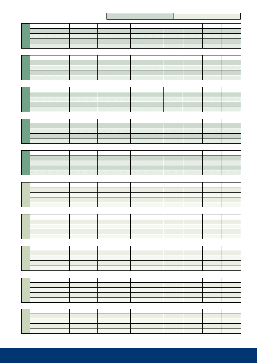
the right Product for Each
and Every application
with unlimited combination possibilities, CEJN’s non-
drip modular couplings are adaptable to most applica-
tions and system requirements. This means customers
will no longer be burdened with searching out applica-
tion-worthy couplings. CEJN has already done the work
for them by incorporating just what customers want and
need most in a modular coupling line – versatility and
virtually spillage-free performance.
The part number listing on Page 6 includes basic cou-
pling and nipple combinations and reflects only a small
portion of combinations that are possible by varying
seals, threads, or other product features.
the fluid series includes both valved and valveless
couplings and nipples, which further extend application
possibilities. valved styles are one-hand operated and
are the most commonly used version in fluid system
applications. due to their construction, the valveless
couplings require two hands for connection/disconnec-
tion and are useful in those applications in which fluid
loss upon disconnection may not be critical.
three configurations are available in the extensive
standard range:
• Single shutoff (must utilize a coupling and valveless
nipple)
• Double shutoff
• Straight through
the series is compatible with working pressures up to
20 bar (290 PSI) and temperatures up to 315° C (600°
F), making it suitable for a variety of low-pressure fluid
applications in which lines need to be connected and
disconnected easily, safely, and without spillage. sizes
available include body sizes from 1/4-inch to 1 inch.
CEJN modular couplings are available in nickel-plated
brass with nitrile seals and AISI 316 stainless steel
with viton
®
seals. EPdm and Kalrez
®
seals are avail-
able upon request to comply with specific performance
objectives.
With or without valve
Body Size
Series
Materials
Nickel-plated brass
Stainless steel AISI 316
Flow Capacity
Double shutoff
Single shutoff
Straight through
Max. Working Pressure
Min. Burst Pressure
Nominal Flow Diameter
Kv (Cv) (Double shutoff)
Temperature Range
NBR (Nitrile rubber)
FPM (Viton
®
)
Please note – Colored rings can only withstand heat up to +125ºC (+257ºF)
EPDM
Kalrez
®
Please note – Colored rings can only withstand heat up to +125ºC (+257ºF)
23
1/4"
10 267 0200
10 267 0400
43.5
59.2
23
19
1/4"
10 267 1200
10 267 1400
43.5
59.2
23
19
1/4"
10 267 5200
10 267 5400
48.5
48.5
20
19
1/4"
10 267 6200
10 267 6400
48.5
48.5
20
19
3/8"
10 467 0200
10 467 0400
45.0
61.2
29
22
3/8"
10 467 1200
10 467 1400
45.0
61.2
29
22
3/8"
10 467 5200
10 467 5400
52.0
50.5
24
22
3/8"
10 467 6200
10 467 6400
52.0
50.5
24
22
1/2"
10 567 0200
10 567 0400
52.5
68.2
34
27
1/2"
10 567 1200
10 567 1400
52.5
68.2
34
27
1/2"
10 567 5200
10 567 5400
56.5
55.0
29
27
1/2"
10 567 6200
10 567 6400
56.5
55.0
29
27
3/4"
10 667 0200
10 667 0400
74.2
71.7
41
36
3/4"
10 667 1200
10 667 1400
74.2
71.7
41
36
3/4"
10 667 5200
10 667 5400
66.0
63.0
36
34
3/4"
10 667 6200
10 667 6400
66.0
63.0
36
34
1"
10 767 0200
10 767 0400
82.0
79.0
52
46
1"
10 767 1200
10 767 1400
82.0
79.0
52
46
1"
10 767 5200
10 767 5400
67.5
64.5
44
41
1"
10 767 6200
10 767 6400
67.5
64.5
44
41
1/4"
10 277 0210
10 277 0410
43.5
59.2
23
19
1/4"
10 277 1210
10 277 1410
43.5
59.2
23
19
1/4"
10 277 5210
10 277 5410
48.5
48.5
20
19
1/4"
10 277 6210
10 277 6410
48.5
48.5
20
19
3/8"
10 477 0210
10 477 0410
45.0
61.2
29
22
3/8"
10 477 1210
10 477 1410
45.0
61.2
29
22
3/8"
10 477 5210
10 477 5410
52.0
50.5
24
22
3/8"
10 477 6210
10 477 6410
52.0
50.5
24
22
1/2"
10 577 0210
10 577 0410
52.5
68.2
34
27
1/2"
10 577 1210
10 577 1410
52.5
68.2
34
27
1/2"
10 577 5210
10 577 5410
56.5
55.0
29
27
1/2"
10 577 6210
10 577 6410
56.5
55.0
29
27
3/4"
10 677 0210
10 677 0410
74.2
71.7
41
36
3/4"
10 677 1210
10 677 1410
74.2
71.7
41
36
3/4"
10 677 5210
10 677 5410
66.0
63.0
39
36
3/4"
10 677 6210
10 677 6410
66.0
63.0
39
36
1"
10 777 0210
10 777 0410
82.0
79.0
52
46
1"
10 777 1210
10 777 1410
82.0
79.0
52
46
1"
10 777 5210
10 777 5410
67.5
64.5
44
41
1"
10 777 6210
10 777 6410
67.5
64.5
44
41
standard range
brass (Nbr seal)
stainless steel (FPm seal)
Series 267
description
Connection
Part No. g-thread
Part No. NPt-thread length
(G)
length
(NPT)
diameter
Hexagon
Coupling, valveless
Female
Coupling, valved
Female
Nipple, valveless
Female
Nipple, valved
Female
Series 467
description
Connection
Part No. g-thread
Part No. NPt-thread length
(G)
length
(NPT)
diameter
Hexagon
Coupling, valveless
Female
Coupling, valved
Female
Nipple, valveless
Female
Nipple, valved
Female
Series 567
description
Connection
Part No. g-thread
Part No. NPt-thread length
(G)
length
(NPT)
diameter
Hexagon
Coupling, valveless
Female
Coupling, valved
Female
Nipple, valveless
Female
Nipple, valved
Female
Series 667
description
Connection
Part No. g-thread
Part No. NPt-thread length
(G)
length
(NPT)
diameter
Hexagon
Coupling, valveless
Female
Coupling, valved
Female
Nipple, valveless
Female
Nipple, valved
Female
Series 767
description
Connection
Part No. g-thread
Part No. NPt-thread length
(G)
length
(NPT)
diameter
Hexagon
Coupling, valveless
Female
Coupling, valved
Female
Nipple, valveless
Female
Nipple, valved
Female
Series 277
description
Connection
Part No. g-thread
Part No. NPt-thread length
(G)
length
(NPT)
diameter
Hexagon
Coupling, valveless
Female
Coupling, valved
Female
Nipple, valveless
Female
Nipple, valved
Female
Series 477
description
Connection
Part No. g-thread
Part No. NPt-thread length
(G)
length
(NPT)
diameter
Hexagon
Coupling, valveless
Female
Coupling, valved
Female
Nipple, valveless
Female
Nipple, valved
Female
Series 577
description
Connection
Part No. g-thread
Part No. NPt-thread length
(G)
length
(NPT)
diameter
Hexagon
Coupling, valveless
Female
Coupling, valved
Female
Nipple, valveless
Female
Nipple, valved
Female
Series 677
description
Connection
Part No. g-thread
Part No. NPt-thread length
(G)
length
(NPT)
diameter
Hexagon
Coupling, valveless
Female
Coupling, valved
Female
Nipple, valveless
Female
Nipple, valved
Female
Series 777
description
Connection
Part No. g-thread
Part No. NPt-thread length
(G)
length
(NPT)
diameter
Hexagon
Coupling, valveless
Female
Coupling, valved
Female
Nipple, valveless
Female
Nipple, valved
Female
all thread connections are listed according to iso standards. all measurements are in mm. Check with an authorized CEJN distributor for availability and prices.
24
19 958 1240
8.0 x 12.0
10 / 145
100
19 958 1640
11.0 x 16.0
10 / 145
100
8.0 x 12.0
10 321 1062
10 321 5062
-
-
11.0 x 16.0
10 321 1066
10 321 5066
10 411 1066
10 411 5066
8.0 x 12.0
1/4"
19 958 1262
19 958 1212
19 958 1292
19 958 1242
8.0 x 12.0
3/8"
19 958 1264
19 958 1214
19 958 1294
19 958 1244
11.0 x 16.0
1/2"
19 958 1665
19 958 1615
19 958 1695
19 958 1645
thread connections are listed according to iso standards. see Page 30 for additional information. Check with an authorized CEJN distributor for availability and prices.
Pressure,
b
ar (P
si
)
Temperature in ºC (ºF)
Part No.
Size ID x OD (mm)
Working Pressue (bar/PSI)
Total Length per Roll (m)
W
at
er
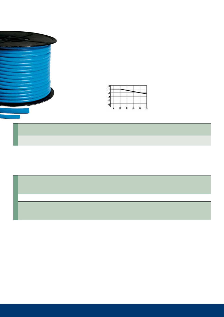
stream-line straight braided Hose
For water
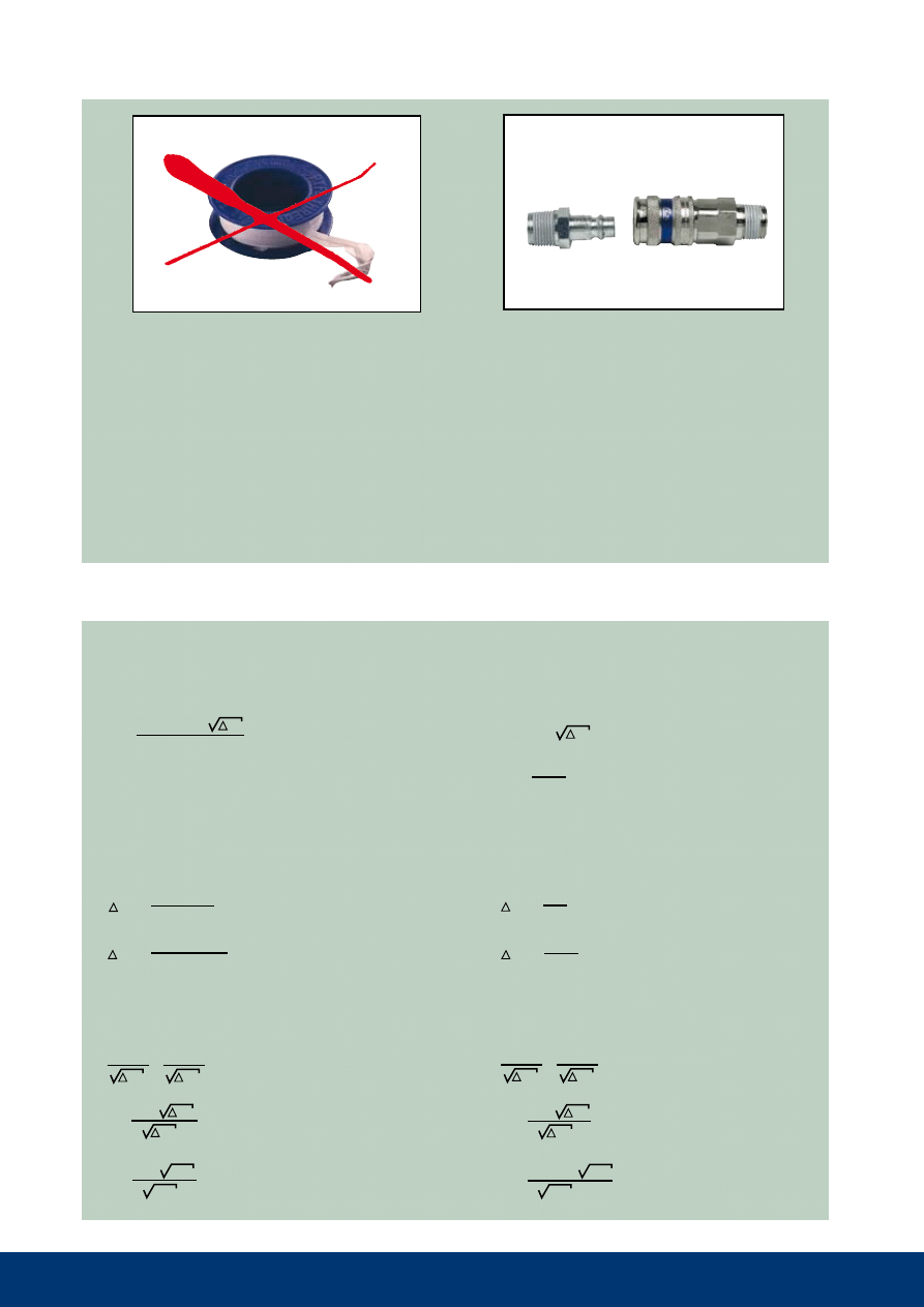
CEJN stream-line straight polyurethane hose, designed for working
pressures up to 10 bar, is suitable for both water and compressed air
applications. when compressed air lines are in prolonged contact with
water, use this hose instead of an air hose to ensure proper function.
Flexible and long lasting, it features two layers of blue ether-based
Pur and a reinforced middle layer of polyester fiber. this construction
gives the hose an extended temperature range of -30 ºC to +60 ºC.
Additional sizes are available upon request.
meter markings are indicated on the hose to make cutting and
assembly easy.
Hose
Fittings
Hose id x od
adapter
r thread
r thread
NPt thread
NPt thread
dim. mm
male thread with swivel
without swivel
with swivel
without swivel
stream-line Hose adapters
For series 321, series 411 and with standard thread
other CEJN Products
suitable for Fluid applications
Other CEJN coupling series may be suitable for fluid applications, depending on working pressure and media. In addition, CEJN's range of
breathing air couplings also includes the following brass styles:
•
Series 221 – Couplings with a "large-grip" locking sleeve that is interchangeable with Standard 221 nipples
•
Series 341, 344 – single shutoff couplings and nipples with an integrated safety feature that protects against unintentional disconnection
•
Series 345, 347 – double shutoff couplings and nipples with an integrated safety feature that protects against unintentional disconnection
•
Series 346 – Single or double shutoff couplings and nipples in AISI 316 stainless material with an integrated safety feature that protects against
unintentional disconnection.
CEJN also offers stainless/chemical nickel-plated versions of Series 116 couplings in its high-pressure hydraulics range for extremely high
pressures up to 1500 bar.
brochures available on other CEJN products are listed on Page 31.
Coupling 321
Nipple 321
Coupling 411
Nipple 411
25
19 900 3211
G 1/4” - G 1/8”
19 900 3221
G 3/8” - G 1/8”
19 900 3222
G 3/8” - G 1/4”
19 900 3232
G 1/2” - G 1/4”
19 900 3234
G 1/2” - G 3/8”
19 900 3244
G 3/4” - G 3/8”
19 900 3245
G 3/4” - G 1/2”
19 900 4302
G 1/4”
19 900 4304
G 3/8”
19 900 4305
G 1/2”
19 900 4307
G 3/4”
19 900 5302
G 1/4”
19 900 5304
G 3/8”
19 900 5305
G 1/2”
19 900 5309
G 1”
19 900 5322
G 1/4”
19 900 5324
G 3/8”
19 900 5325
G 1/2”
19 900 5332
G 1/4”
19 900 5334
G 3/8”
19 900 5335
G 1/2”
19 900 5361
G 1/8”
19 900 5362
G 1/4”
19 900 5364
G 3/8”
19 900 5365
G 1/2”
19 900 5371
G 1/8”
19 900 5372
G 1/4”
19 900 5374
G 3/8”
19 900 5375
G 1/2”
19 900 5379
G 1”
19 900 5382
G 1/4”
19 900 5384
G 3/8”
19 900 5385
G 1/2”
19 900 5916
G 1/4”
19 900 5912
G 3/8”
19 900 5902
G 1/2”
19 900 5920
G 1/4”
19 900 5921
G 3/8”
19 900 5925
G 1/2”
19 900 5906
G 1/8”
19 900 5905
G 1/4”
19 900 5904
G 3/8”
19 900 5903
G 1/2”
19 900 5932
G 1/4”
19 900 5934
G 3/8”
19 900 5935
G 1/2”
19 900 0211
R 1/8” - 3/16"
19 900 0212
R 1/8” - 1/4”
19 900 0221
R 1/4” - 3/16”
19 900 0222
R 1/4” - 1/4”
19 900 0223
R 1/4” - 5/16”
19 900 0224
R 1/4” - 3/8”
19 900 0225
R 1/4” - 1/2”
19 900 0232
R 3/8” - 1/4”
19 900 0233
R 3/8” - 5/16”
19 900 0234
R 3/8” - 3/8”
19 900 0235
R 3/8” - 1/2”
19 900 0242
R 1/2” - 1/4”
19 900 0243
R 1/2” - 5/16”
19 900 0244
R 1/2” - 3/8”
19 900 0245
R 1/2” - 1/2”
19 900 0246
R 1/2” - 5/8”
19 900 0247
R 1/2” - 3/4”
19 900 0254
R 3/4” - 3/8”
19 900 0255
R 3/4” - 1/2”
19 900 0256
R 3/4” - 5/8”
19 900 0257
R 3/4” - 3/4”
19 900 0262
1/4” - 1/4”
19 900 0264
3/8” - 3/8”
19 900 0265
1/2” -
1/2”
19 900 1210
G 1/8” - G 1/8”
19 900 1211
G 1/4” - G 1/8”
19 900 1212
G 1/4” - G 1/4”
19 900 1214
G 1/4” - G 3/8”
19 900 1215
G 1/4” - G 1/2”
19 900 1220
G 3/8” - G 1/8”
19 900 1224
G 3/8” - G 3/8”
19 900 1225
G 3/8” - G 1/2”
19 900 1227
G 3/8” - G 3/4”
19 900 1229
G 1/2” - G 3/4”
19 900 1235
G 1/2” - G 1/2”
19 900 1249
G 3/4” - G 3/4”
19 900 2201
G 1/8” - G 1/8”
19 900 2202
G 1/8” - G 1/4”
19 900 2204
G 1/8” - G 3/8”
19 900 2212
G 1/4” - G 1/4”
19 900 2214
G 1/4” - G 3/8”
19 900 2224
G 3/8” - G 3/8”
19 900 2225
G 3/8” - G 1/2”
19 900 2235
G 1/2” - G 1/2”
19 900 2237
G 1/2” - G 3/4”
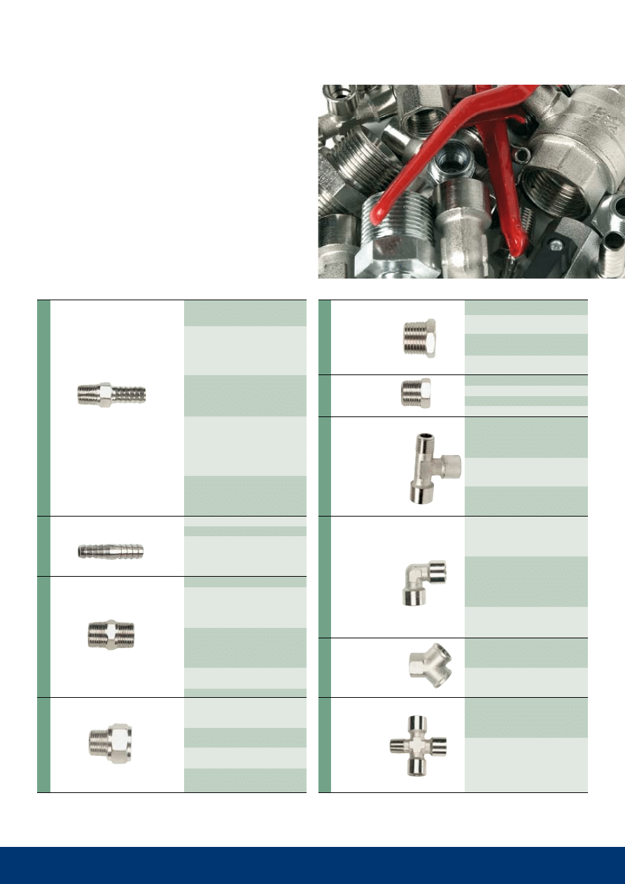
series 900
Connectors, adapters, bushings, and Plugs
Technical Data
Max. working pressure: 35 bar (507 PSI)
material: Plated brass
CEJN offers a wide range of hose connectors; male-to-male
adapters; bushings; plugs; t-, l-, and Y-pieces; and crosses for
compressed air and liquid applications. A wide range of both
cylindrical and conical threads is available for maximum flexibil-
ity in a variety of applications. all adapters are plated for better
protection against corrosion and feature a high burst pressure/
working pressure factor of safety.
Cross
Y-piece
L-piece
T-piece
Plug
Reducing
Adap.
Part No.
Connection
Check with an authorized CEJN distributor for availability and prices.
Male/Female
male
Female/Female/Female
Female/Male/Female
Female/Female/Male
Male/Male
Female/Female
Male/Female
Female/Female/Female
Female/Male/Female
Female/Female/Female/Female
Male/Female/
Female/Male
Adapters
Male
Adapter
H
os
e
M
en
de
rs
Hose
Tail
Nipple
Part No.
Connection
Male/Hose
Hose/Hose
Male/Male
Male/Female
26
Q
1
P
P
P
1
Q
2
P
2
=
=
= Cv
Kv
Kv
Kv
Q
Q
x
x
60
1000
0.86
60
x
x
= Kv
Cv 0.86
x
1000
P
= Cv
Q
x
(
)
2
P= Cv
Q
( )
2
P
1.99 bar
=
=
=
Q
2
Q
1
P
1
P
2
=
=>
Q
1
P
1
Q
2
P
2
=
=>
2.34
55
x
x
60
1000
(
)
2
P
30.4 PSI
=
=
2.72
15
( )
2
x
Q
2
55.5 l/min
17.2 GPM
68
3
2
=
=
x
Q
2
Q
1
P
1
P
2
=
x
Q
2
12.16
20
40
=
=
x
Q
1
P
P
P
1
Q
2
P
2
=
=
= Cv
Kv
Kv
Kv
Q
Q
x
x
60
1000
0.86
60
x
x
= Kv
Cv 0.86
x
1000
P
= Cv
Q
x
(
)
2
P= Cv
Q
( )
2
P
1.99 bar
=
=
=
Q
2
Q
1
P
1
P
2
=
=>
Q
1
P
1
Q
2
P
2
=
=>
2.34
55
x
x
60
1000
(
)
2
P
30.4 PSI
=
=
2.72
15
( )
2
x
Q
2
55.5 l/min
17.2 GPM
68
3
2
=
=
x
Q
2
Q
1
P
1
P
2
=
x
Q
2
12.16
20
40
=
=
x
Kv= Flow in m³/hour @ ∆P=1 bar
Cv=Flow in gallon/minute @ ∆P=1 PSI
Q= Flow (l/min)
Q= Flow (gallon/min)
Kv= Flow constant (m³/h)
Cv= Flow constant (gallon/min)
∆P= Pressure drop (bar)
∆P= Pressure drop (PSI)
recalculation of Pressure drop or water Flow values
Determine the pressure drop at 55 l/min for Series 321.
For Series 321, Kv=2.34
For Series 321, Cv=2.72
with a Flowchart:
∆P 3 bar gives a flow of 68 l/min.
∆P 20 PSI gives a flow of 12.16 GPM.
What is the flow at ∆P 2 bar?
What is the flow at ∆P 40 PSI?
CEJN Pre-applied Thread Sealant
CEJN's thread sealant is a dry, non-hardened product that seals against pressure immediately after assembly. The thread
sealant does not lock the threaded components together, which makes the coupling/nipple easy to remove.
the sealant is gas- and water-approved in accordance with Ktw, dvgw, Övgw, and svgw. it is vibration resistant, water-
based, and free of any organic solvents. Seals up to 150 bar. Max. temperature: 150° C.
• Ready to be attached
• Seals directly
• Requires unnecessary time to apply thread tape or fluid.
• Danger of leakage if the tape or fluid isn't applied properly.
• Danger of loose tape or fluid getting onto the coupling or
air system and causing problems.
Series 321, 322, and 324
all couplings with male threads are pre-applied with
thread sealant.
Pre-applied nippels available on request.
Thread Sealant
Flow Calculation

27
Maintenance Tips
To guarantee a coupling’s function, quality and lifetime, be sure to:
• Keep the coupling and nipple clean and dry. Dust and foregin matters may cause leakage.
• Avoid front-end impacts to the coupling and nipple.
• Check the sealing of the coupling and its moving parts regularly. If necessary, replace the coupling.
• Check the nipples on a regular basis. If they are heavily worn or marked, replace them. Worn nipples lead to greater wear on
the couplings.
• Choose the proper connection for the application. Oversized connections cause unnecessary wear to the coupling.
• Avoid overtorquing when installing couplings and nipples.
Technical Data
Water flow: .............................
Sound level: ..........................
Working pressure: ...............
Burst pressure: ....................
Weight: ...................................
Temperature range: .............
Kv and Cv value: ..................
Nominal flow diameter: .......
Sealing Materials
MATERiALS
FEATuRES
TEMPERATuRE RANgE
MEDiA
resistant to water, gasoline, grease, mineral
oil, heat, and alkalis. sensitive to ozone.
recommended for gasoline, oils, and acids.
weather-resistant. Not recommended for hot
steam.
suitable for hot water, alkalines, and acids.
Not recommended for mineral oil.
Highly aggressive chemicals,pharmaceuticals,
aerospace, and petroleum applications, oil and
gas recovery, semiconductor wafer processing
-30°C to +100°C
(-22°F to +212°F)
-15°C to +200°C
(-5°F to +392°F)
-40°C to +150°C
(-40°F to +302°F)
+315ºC
(+600ºF)
Compressed air,
oil, water
Chemicals, hot air
water
Chemicals
oil, steam
NBR
(Nitrile rubber
buna-N)
FPM
(Fluorocarbon
rubber viton
®
)
EPDM
(Ethylene Propylene rub-
ber EPDM/EPM)
Kalrez
®
Contact CEJN for more detailed information regarding sealing material and chemical compatibility with CEJN couplings.
All technical data are measured according to CEJN standards. Contact CEJN for more detailed information.
Measured within an accuracy of ±5%. The unit used is "l/min" and stands for liter per minute.
measured at a distance of 1 meter in front of and 1 meter beside a 90° angle in front of the object.
The unit used is "dB (A)" and stands for decibel on the "A" scale.
Specified in bar and PSI (pounds per square inch). Working pressure is often stipulated in varying
national and international standards for quick-connect coupling.
Specified in bar and PSI and measured within an accuracy of ±2%. Minimum burst pressure is cal-
culated by mutiplying the safety factor by the working pressure.
Measured in "g" (gram) as an average of 10 pcs.
Measured in Celsius degrees within an accuracy of ±2°C (±3.6°F).
See Page 26.
specifies the smallest flow area through the coupling and nipple.

28
units, Conversion Tables, and Formulas
Pressure
FRoM
To
MuLTiPLY BY
ExAMPLE
atm
(atmosphere)
bar
1.01325
1.1 atm x 1.01325 = 1.115 bar
atm
mPa
0.10132
1.1 atm x 0.10132 = 0.111 mPa
atm
PSI
14.696
1.1 atm x 14.695 = 16.166 PSI
bar
atm
0.98692
10 bar x 0.98692 = 9.8692 atm
bar
mPa
0.1
10 bar x 0.1 = 1.0 mPa
bar
PSI
14.504
10 bar x 14.504 = 145 PSI
mPa
(megapascal)
atm
9.8692
10 MPa x 9.8692 = 98.692 atm
mPa
bar
10
10 mPa x 10 = 100 bar
MPa
PSI
145.0
10 MPa x 145.0 = 1450 PSI
Psi
(pounds / square inch)
atm
0.068
100 PSI x 0.068 = 6.80 atm
PSI
bar
0.0689
100 PSI x 0.0689 = 6.89 bar
PSI
MPa
0.00689
100 PSI x 0.00689 = 0.689 MPa
Flow
FRoM
To
MuLTiPLY BY
ExAMPLE
Volume
FRoM
To
MuLTiPLY BY
ExAMPLE
CFm
(cubic feet / minute)
l/min
28.32
100 CFM x 28.32 = 2832 l/min
CFM
l/s
0.472
100 CFM x 0.472 = 47.2 l/s
CFm
m
3
/h
1.699
100 CFM x 1.699 = 169.9 m
3
/h
l/min
(liter / minute)
CFM
0.0353
100 l/min x 0.0353 = 3.5 CFM
l/min
l/s
0.0167
100 l/min x 0.0167 = 1.7 l/s
l/min
m
3
/h
0.06
100 l/min x 0.06 = 6 m
3
/h
l/s
(liter / second)
CFM
2.119
10 l/s x 2.119 x 21.2 CFM
l/s
l/min
60
10 l/s x 60 = 600 l/min
l/s
m
3
/h
3.6
10 l/s x 3.6 = 36 m
3
/h
m
3
/h
(cubic meter / hour)
CFM
0.5885
10 m
3
/h x 0.5885 = 5.885 CFM
m
3
/h
l/min
16.667
10 m
3
/h x 16.667 = 166.7 l/min
m
3
/h
l/s
0.2777
10 m
3
/h x 0.2777 = 2.777 l/s
ft
3
(cubic foot)
gl UK
6.228
10 ft
3
x 6.228 = 62.28 gl UK
ft
3
gl U.S.
7.48
10 ft
3
x 7.48 = 74.8 gl U.S.
ft
3
l
28.32
10 ft
3
x 28.32 = 283.2 l
ft
3
m
3
0.0283
10 ft
3
x 0.0283 = 0.283 m
3
gl uK
(gallon uK)
ft
3
0.1605
10 gl UK x 0.1605 = 1.605 ft
3
gl uK
gl u.s.
1.2009
10 gl uK x 1.2009 = 12.009 gl u.s.
gl UK
l
4.546
10 gl UK x 4.546 = 45.46 l
gl uK
m
3
0.0045
10 gl UK x 0.0045 = 0.045 m
3
gl u.s.
(gallon u.s.)
ft
3
0.1336
10 gl U.S. x 0.1336 = 1.336 ft
3
gl U.S.
gl UK
0.8326
10 gl U.S. x 0.8326 = 8.326 gl UK
gl U.S.
l
3.785
10 gl U.S. x 3.785 = 37.85 l
gl u.s.
m
3
0.0037
10 gl U.S. x 0.0037 = 0.037 m
3
l
(liter)
ft
3
0.0353
100 l x 0.0353 = 3.53 ft
3
l
gl uK
0.220
100 l x 0.220 = 22.0 gl uK
l
gl U.S.
0.264
100 l x 0.264 = 26.4 gl U.S.
l
m
3
0.001
100 l x 0.001 = 0.1 m
3
m
3
(cubic meter)
ft
3
35.3
10 m
3
x 35.3 = 353 ft
3
m
3
gl UK
219.96
10 m
3
x 219.96 = 2199.6 gl UK
m
3
gl U.S.
264.17
10 m
3
x 264.17 = 2641.7 gl U.S.
m
3
l
1000
10 m
3
x 1000 = 10 000 l
Force
FRoM
To
MuLTiPLY BY
ExAMPLE
lbf
(pound force)
kp
0.454
10 lbf x 0.454 = 4.54 kp
lbf
N
4.448
10 lbf x 4.448 = 44.48 N
kp
(kilogram force)
lbf
2.205
10 kp x 2.205 = 22.05 lbf
kp
N
9.806
10 kp x 9.806 = 98.06 N
N
(newton)
lbf
0.2248
10 N x 0.2248 = 2.25 lbf
N
kp
0.1020
10 N x 0.1020 = 1.02 kp

29
Equivalent Chart for Hose and Hose Fittings
5 x 8
0.196 x 0.314
3/16" (0.1875 inch)
6.5 x 10
0.255 x 0.393
1/4" (0.250 inch)
8 x 12
0.314 x 0.472
5/16" (0.3125 inch)
9.5 x 13.5
0.374 x 0.531
3/8" (0.375 inch)
11 x 16
0.433 x 0.630
7/16" (0.4375 inch)
inner Dia. x outer Dia. in mm
inner Dia. x outer Dia. in inch
u.S. Nominal
6.3
0.248
1/4" (0.250 inch)
10
0.393
3/8" (0.375 inch)
13
0.512
1/2" (0.5 inch)
16
0.630
5/8" (0.625 inch)
19
0.748
3/4" (0.75 inch)
Connection Size in mm
Connection Size in inch
u.S. Nominal
Hose Size
Hose Connection Size
Mass
FRoM
To
MuLTiPLY BY
ExAMPLE
Torque
FRoM
To
MuLTiPLY BY
ExAMPLE
kpm
(kilo pound meter)
lbfft
7.233
10 kpm x 7.233 = 72.33 lbfft
kpm
Nm
9.81
10 kpm x 9.81 = 98.1 Nm
lbfft
(pound force foot)
Nm
1.356
10 kpm x 1.356 = 13.56 Nm
lbfft
Nm
0.1383
10 kpm x 0.1383 = 1.38 kpm
Nm
(newton meter)
kpm
0.1020
10 Nm x 0.1020 = 1.02 kpm
Nm
lbfft
0.7376
10 Nm x 0.7376 = 7.38 lbfft
Length
FRoM
To
MuLTiPLY BY
ExAMPLE
ft
(foot)
inch
12
10 ft x 12 = 120 inch
ft
m
0.3048
10 ft x 0.3048 = 3.048 m
ft
mm
304.8
10 ft x 304.8 = 3048 mm
inch
ft
0.0833
10 inch x 0.0833 = 0.833 ft
inch
m
0.0254
10 inch x 0.0254 = 0.254 m
inch
mm
25.4
10 inch x 25.4 = 254 mm
m
(meter)
ft
3.28083
10 m x 3.28083 = 32.8083 ft
m
inch
39.3699
10 m x 39.3699 = 393.699 inch
m
mm
1000
10 m x 1000 = 10 000 mm
mm
(millimeter)
ft
0.00328
10 mm x 0.00328 = 0.0328 ft
mm
inch
0.0393
10 mm x 0.0393 = 0.393 inch
mm
m
0.001
10 mm x 0.001 = 0.01 m
g
(gram)
kg
0.001
10 g x 0.001 = 0.01 kg
g
lb
0.0022
10 g x 0.0022 = 0.022 lb
g
oz
0.0352
10 g x 0.0352 = 0.352 oz
kg
(kilogram)
g
1000
10 kg x 1000 = 10 000 g
kg
lb
2.205
10 kg x 2.205 = 22.05 lb
kg
oz
35.273
10 kg x 35.273 = 352.73 oz
lb
(pound)
g
453.9
10 lb x 453.9 = 4539 g
lb
kg
0.4539
10 lb x 0.4539 = 4.539 kg
lb
oz
16
10 lb x 16 = 160 oz
oz
(ounce)
g
28.349
10 oz x 28.349 = 283.49 g
oz
kg
0.0283
10 oz x 0.0283 = 0.283 kg
oz
lb
0.0625
10 oz x 0.0625 = 0.625 lb
30
L
L
L
L
Ø
L
Ø
L
Ø
L
Ø
L
Ø
L
Ø
6.3 mm (1/4")
-
18.0
8 mm (5/16")
-
18.0
10 mm (3/8")
-
21.0
13 mm (1/2")
-
21.0
16 mm (5/8")
-
23.0
5 x 8 mm
-
15.0
6.5 x 10 mm
-
17.0
8 x 12 mm
-
19.0
9.5 x 13.5 mm
-
21.0
11 x 16 mm
-
25.0
1/4"
-
19.0
3/8"
-
23.0
1/2"
-
26.0
R 1/8"
10.2
7.4
R 1/4"
13.6
11.0
R 3/8"
17.2
11.0
R 1/2"
21.7
15.0
R 3/4"
27.1
16.3
Rc 1/8"
8.3
7.4
Rc 1/4"
11.0
11.0
Rc 3/8"
14.5
11.4
Rc 1/2"
18.0
15.0
Rc 3/4"
23.5
16.3
G 1/8"
9.6
8.0
G 1/4"
13.0
10.0
G 3/8"
16.5
10.0
G 1/2"
20.8
12.0
G 3/4"
26.3
12.0
G 1/8"
8.75
7.4
G 1/4"
11.8
11.0
G 3/8"
15.25
11.4
G 1/2"
19.0
15.0
G 3/4"
24.5
16.3
NPT 1/8"
10.5
6.7
NPT 1/4"
14.0
10.2
NPT 3/8"
17.5
10.4
NPT 1/2"
21.8
13.6
NPT 3/4"
27.1
13.9
NPT 1/8"
8.5
6.9
NPT 1/4"
11.0
10.0
NPT 3/8"
14.5
10.3
NPT 1/2"
18.0
13.6
NPT 3/4"
23.0
14.1
Connections and Thread Standards
Connection
Ø
(mm)
L
(mm)
Hose Connection
standard hose barb for hose clamp
Stream-Line Connection
Hose barb with nut cap for reusable and
safe hose clamping
CEJN-Lock Connection
For special non-clamping hose
R/Rc Thread Connection
Conical Pipe thread Connection
According to ISO 7/1
(other common descriptions are bsPt, Kr)
Male:
ie. R 1/4"
Female:
ie. Rp 1/4" (parallel)
ie. Rc 1/4" (taper)
g Thread Connection
Cylindrical Pipe thread Connection
According to ISO 228/1
(other common descriptions are bsP, r)
Male:
ie. G 1/4"
Female (ISO 1179): ie. G 1/4"
NPT Thread Connection
National Pipe thread american standard
according to ANSI/ASME B 1.20.1
Male and female:
ie. 1/4" NPT
Male Thread
Female Thread
Male Thread
Female Thread
Male Thread
Female Thread
31
other Products Available from CEJN
To obtain product information or product brochures, contact your nearest
CEJN office or representative, or visit us on the Internet at
www.cejn.com

The Global
Quick Connect Specialist
Copyright
©
2009
CEJN
ab
09
001
2255
/
2009-07
/ CEJN
AB
Skövde,
Sweden
Fluids
Wyszukiwarka
Podobne podstrony:
Non Drip eng webb
HP eng webb
chrystus jest zyciem mym ENG
Przegląd rozwiązań konstrukcyjnych wtryskarek (ENG)
Assembler ENG
Frequenzimetro eng 2003
PM [R2] Sylabus ENG
P000476 D Eng Main dimensions
Eurocode 3 Part 1 11 Pren 1993 1 11 (Eng)
Humulon and lupulon eng
Konwencja w sprawie zapobiegania i karania zbrodni ludobójstwa eng
Hyd prd cat 2009 english webb
Curriculum vitae Team III ENG
P000722 A Eng Lower preassembly
Polymer Processing With Supercritical Fluids V Goodship, E Ogur (Rapra, 2004) Ww
P000718 A Eng Vertical shaft assembly
więcej podobnych podstron