HYDRAULIC SYSTEM
H14.00-20.00XM [A214];
H16.00-18.00XM-12EC (H400-450XM-EC) [A214]
PART NO. 897994
1900 SRM 666
SAFETY PRECAUTIONS
MAINTENANCE AND REPAIR
• When lifting parts or assemblies, make sure all slings, chains, or cables are correctly
fastened, and that the load being lifted is balanced. Make sure the crane, cables, and
chains have the capacity to support the weight of the load.
• Do not lift heavy parts by hand, use a lifting mechanism.
• Wear safety glasses.
• DISCONNECT THE BATTERY CONNECTOR before doing any maintenance or repair
on electric lift trucks.
• Disconnect the battery ground cable on internal combustion lift trucks.
• Always use correct blocks to prevent the unit from rolling or falling. See HOW TO PUT
THE LIFT TRUCK ON BLOCKS in the Operating Manual or the Periodic Mainte-
nance section.
• Keep the unit clean and the working area clean and orderly.
• Use the correct tools for the job.
• Keep the tools clean and in good condition.
• Always use HYSTER APPROVED parts when making repairs. Replacement parts
must meet or exceed the specifications of the original equipment manufacturer.
• Make sure all nuts, bolts, snap rings, and other fastening devices are removed before
using force to remove parts.
• Always fasten a DO NOT OPERATE tag to the controls of the unit when making repairs,
or if the unit needs repairs.
• Be sure to follow the WARNING and CAUTION notes in the instructions.
• Gasoline, Liquid Petroleum Gas (LPG), Compressed Natural Gas (CNG), and Diesel fuel
are flammable. Be sure to follow the necessary safety precautions when handling these
fuels and when working on these fuel systems.
• Batteries generate flammable gas when they are being charged. Keep fire and sparks
away from the area. Make sure the area is well ventilated.
NOTE:
The following symbols and words indicate safety information in this
manual:
WARNING
Indicates a condition that can cause immediate death or injury!
CAUTION
Indicates a condition that can cause property damage!

Hydraulic System
Table of Contents
TABLE OF CONTENTS
General ...............................................................................................................................................................
Description and Operation ................................................................................................................................
Main Control Valve ...................................................................................................................................
Remote Control Valve................................................................................................................................
Pilot Supply Valve .....................................................................................................................................
Auxiliary Control Valve.............................................................................................................................
Selector Valves...........................................................................................................................................
Steering System ........................................................................................................................................
Main Control Valve Repair ................................................................................................................................
Description .....................................................................................................................................................
Lifting ........................................................................................................................................................
Lowering ....................................................................................................................................................
Tilt Spool ....................................................................................................................................................
Priority Valve.............................................................................................................................................
Relief Valves ..............................................................................................................................................
Repairs ...........................................................................................................................................................
Remove.......................................................................................................................................................
Disassemble ...............................................................................................................................................
Clean and Inspect......................................................................................................................................
Assemble ....................................................................................................................................................
Install .........................................................................................................................................................
Checks and Adjustments...............................................................................................................................
Relief Pressures Check .............................................................................................................................
Remote Control Valve Repair ............................................................................................................................
Description .....................................................................................................................................................
Operation .......................................................................................................................................................
Repairs ...........................................................................................................................................................
Remove.......................................................................................................................................................
Disassemble ...............................................................................................................................................
Clean and Inspect......................................................................................................................................
Assemble ....................................................................................................................................................
Install .........................................................................................................................................................
Adjust .........................................................................................................................................................
Pilot Supply Valve Repair..................................................................................................................................
Description and Operation ............................................................................................................................
Repairs ...........................................................................................................................................................
Checks and Adjustments...............................................................................................................................
Relief Valve, Check and Adjust.................................................................................................................
Pressure Reduction Valves, Check ...........................................................................................................
Auxiliary Control Valve Repair .........................................................................................................................
Description and Operation ............................................................................................................................
Repairs ...........................................................................................................................................................
Remove.......................................................................................................................................................
Disassemble ...............................................................................................................................................
Clean and Inspect......................................................................................................................................
Assemble ....................................................................................................................................................
Install .........................................................................................................................................................
Check and Adjust ......................................................................................................................................
Hydraulic Pump Repair.....................................................................................................................................
General ...........................................................................................................................................................
Repairs ...........................................................................................................................................................
©2002 HYSTER COMPANY
i
Table of Contents
Hydraulic System
TABLE OF CONTENTS (Continued)
Specifications......................................................................................................................................................
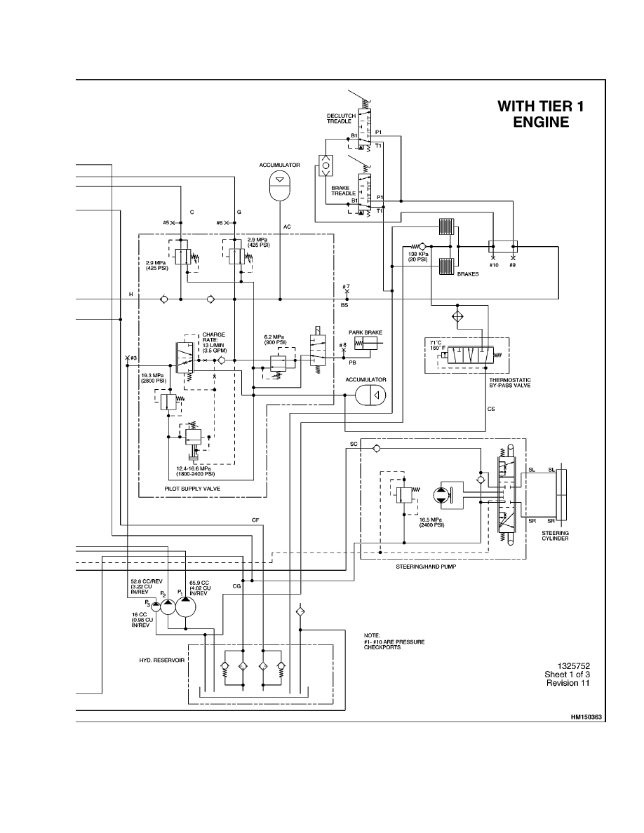
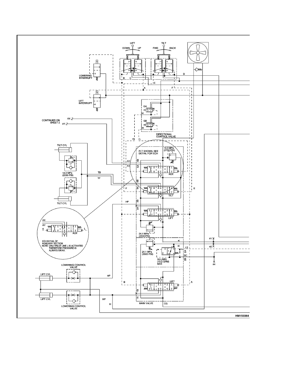
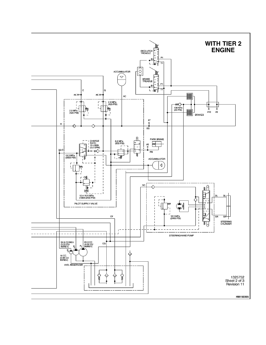
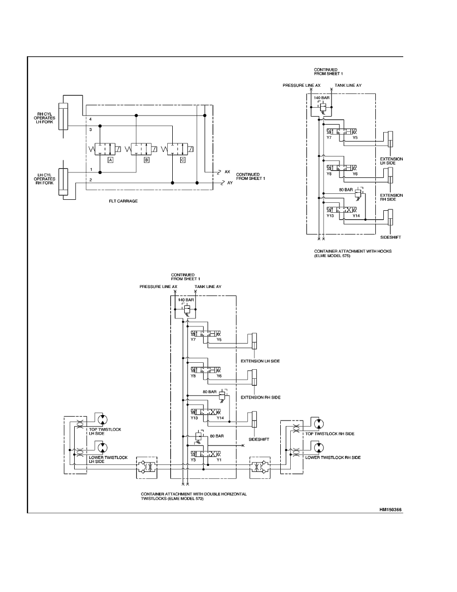
Schematics..........................................................................................................................................................
Figure 12. Hydraulic System Schematic......................................................................................................
Figure 13. Pilot Supply Valve Cartridge Torque Values..............................................................................
Troubleshooting..................................................................................................................................................
Main Control Valve........................................................................................................................................
Remote Control valve ....................................................................................................................................
Pilot Supply Valve..........................................................................................................................................
Auxiliary Control Valve .................................................................................................................................
This section is for the following models:
H14.00-20.00XM [A214];
H16.00-18.00XM-12EC (H400-450XM-EC) [A214]
ii

1900 SRM 666
Description and Operation
General
This section has the description and operation of
the hydraulic system. The section also has repair
procedures and troubleshooting for most of the
components of the hydraulic system. See the sec-
tions Steering System 1600 SRM 671 and Brake
System 1800 SRM 659 for information on these
systems. The section Hydraulic Gear Pumps 1900
SRM 97 has the repair procedures for hydraulic
pumps. The section 1800 SRM 1036 has the repair
procedures for the Accumulator.
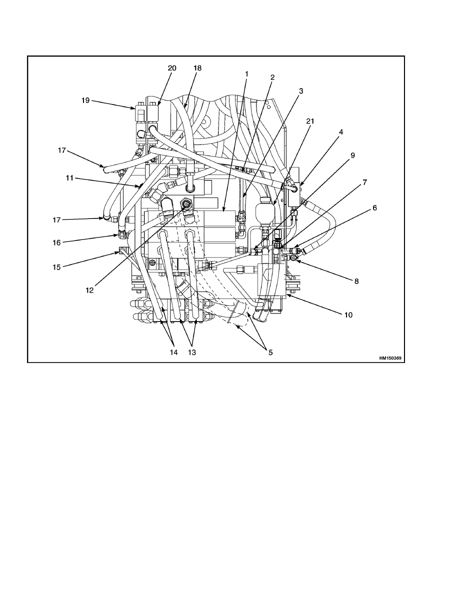
Description and Operation
The hydraulic system includes the circuits for the
mast, steering system, brake system, carriage, and
attachments. See Figure 1 and Figure 12. A three-
section gear pump supplies the flow of oil for the com-
ponents of the hydraulic system. The pump is driven
by a power takeoff arrangement on the transmission
housing. The inlet hoses for the pump are connected
to the hydraulic tank.
The hydraulic system uses a three-section hydraulic
pump. The three sections of the pump supply dif-
ferent parts of the hydraulic system. The smallest
section of the pump supplies oil to the pilot supply
valve. The middle section of the pump supplies oil
to the main control valve for the lift, tilt, and auxil-
iary circuits. The large section of the pump supplies
oil to a priority valve in the main control valve. The
operation of the priority valve is controlled by pilot
pressure in the load sensing circuit of the steering
control unit. Oil that is not needed for steering flows
to the lift circuit.
Most of the valves in the hydraulic system are in-
stalled on a module. The module is installed on rub-
ber isolators in a compartment in the left side of the
frame.
1
Description and Operation
1900 SRM 666
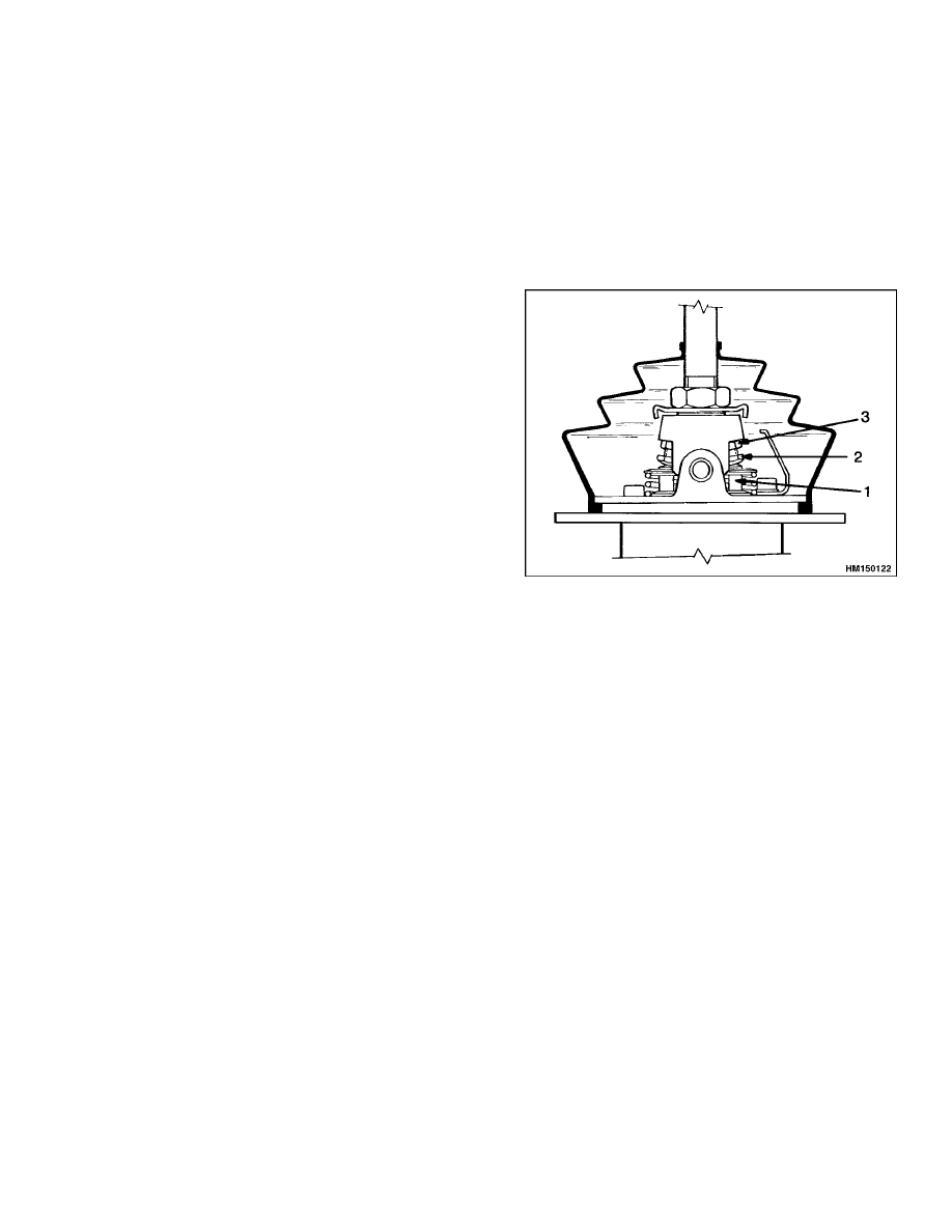
1.
MAIN CONTROL VALVE
2.
RETURN TO TANK
3.
LIFT PILOT SUPPLY
4.
AUXILIARY CONTROL VALVE
5.
SUPPLY FROM PUMP
6.
CHECK PORT - LIFT PILOT
PRESSURE
7.
CHECK PORT - PARKING
BRAKE
8.
CHECK PORT - TILT PILOT
PRESSURE
9.
CHECK PORT -
ACCUMULATOR CHARGE
VALVE
10. PILOT SUPPLY VALVE
11. CHECK PORT - LIFT
CIRCUIT/AUXILIARY
12. CHECK PORT - LIFT
CIRCUIT/STEERING
13. TO TILT CYLINDERS
14. TO LIFT CYLINDERS
15. PILOT SUPPLY - AUXILIARY
16. PILOT SUPPLY - TILT
17. PILOT SUPPLY - LIFT
18. STEERING SUPPLY
19. LIFT INTERRUPT
20. LOWER INTERRUPT
21. ACCUMULATOR
Figure 1. Hydraulic System Components
Main Control Valve
The main control valve controls the steering priority
flow and the lift, lower, tilt, and auxiliary functions.
The control valve has five spools; one for steering pri-
ority, two for the lift circuit, and one each for the tilt
and auxiliary functions.
Remote Control Valve
The remote control valve is controlled by the oper-
ator. The valve has two sections. One section con-
trols the lifting and lowering function and the other
section controls the tilt function. Pilot lines for hy-
draulic oil are connected between the remote control
valve and the main control valve. Movement of the
2

1900 SRM 666
Main Control Valve Repair
spools in the remote control valve actuates the spools
for the lift and tilt circuits. The supply of oil for
the remote control valve comes from the pilot supply
valve.
Pilot Supply Valve
The pilot supply valve controls the flow of oil to the
circuits for the following: remote control valve, aux-
iliary control valve, brake system, and accumulator.
Auxiliary Control Valve
The auxiliary control valve is a solenoid-operated
valve that controls the auxiliary spool in the main
control valve. The operator actuates the auxiliary
control valve with switches in the operator’s com-
partment. The auxiliary spool starts and stops the
flow of oil to the selector valves on the carriage for
the separate hydraulic functions.
The auxiliary
control valve receives oil pilot supply valve.
Selector Valves
The selector valves are solenoid valves that are as-
sembled together and installed on the carriage or at-
tachment. The supply and return ports in the mani-
fold for the selector valves are connected to the con-
trol valve for the carriage and attachment with hoses
on the mast. Each selector valve opens or closes a hy-
draulic circuit to a cylinder or cylinders for a specific
function. Each selector valve is actuated by a switch
that also actuates the auxiliary control valve at the
same time.
Steering System
The oil supply for the steering system comes from the
priority valve in the main control valve. The move-
ment of the priority spool is controlled by a pilot line
(load sensing) from the steering control unit. Oil that
is not used for steering flows to the lift circuit in the
main control valve.
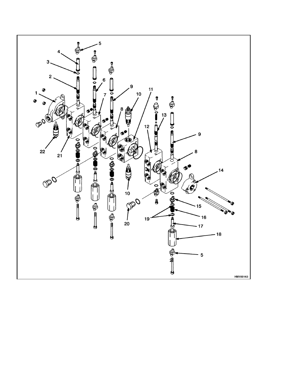
Main Control Valve Repair
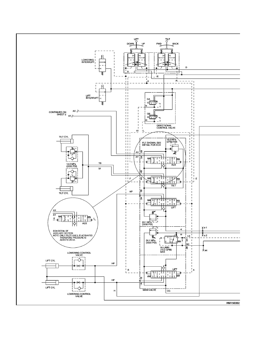
DESCRIPTION
The main control valve controls the flow and pres-
sure of the oil to the steering, lift, and tilt cylinders
and the auxiliary circuit. See Figure 2. The control
valve has five spools; one for steering priority, two
to control lifting and lowering, and one each for tilt
and auxiliary functions. There are three relief valves
in the control valve. The two relief valves for the
lift circuit are set at 24.1 MPa (3500 psi). The re-
lief valve for the tilt and auxiliary circuits is set at
19.0 MPa (2750 psi). The operation of the priority
spool is controlled by pilot pressure from the steer-
ing control unit. Oil that is not needed for steering
flows to the lift circuit.
3
Main Control Valve Repair
1900 SRM 666
1.
OUTLET HOUSING
2.
AUXILIARY SPOOL
3.
O-RING
4.
SPOOL HOUSING
5.
RETAINER
6.
TILT SPOOL
7.
TILT SECTION
8.
LIFT SECTION
9.
LIFT SPOOL
10. LIFT RELIEF VALVE
11. INLET SECTION
12. PRIORITY VALVE SECTION
13. PRIORITY SPOOL
14. END SECTION
15. ADAPTER
16. SPRING AND SPACER
17. CAPSCREW
18. SPRING HOUSING
19. SPRING RETAINER
20. PLUG
21. AUXILIARY SECTION
22. TILT/AUXILIARY RELIEF
VALVE
Figure 2. Main Control Valve
4
1900 SRM 666
Main Control Valve Repair
Lifting
There are two lift spools that control the oil flow to
the lift cylinders. The pilot lines are connected to
both lift spools, and the spools move at the same
time. While one lift spool receives oil directly from
the pump, the other spool receives oil from the pri-
ority valve. The movement of the flow regulator is
controlled by a pilot line from the steering control
unit. When oil is not required for the steering sys-
tem, the flow regulator allows oil to flow to the second
lift spool. The increased oil flow to the lift cylinders
allows the mast lift speed to increase.
When the lift spools are moved to the lift position,
oil pressure moves the load check valves from their
seats. The oil from the control valve flows to the
base of the lift cylinders through the lowering con-
trol valves.
The lines at the top of the lift cylinders are breather
lines. These lines allow for air movement and some
oil to lubricate the cylinder rods and bores.
Lowering
When the lift spools are moved to the lowering posi-
tion, oil from the hydraulic pumps goes through the
control valve to the tank. Oil from the base of the lift
cylinders flows through the lowering control valves
to the main control valve and back to the tank.
Tilt Spool
The tilt spool controls the direction and quantity of
oil to the tilt cylinders. When the spool is moved
to the forward tilt position, oil flows to the bases of
the tilt cylinders. Oil from the rod end of each tilt
cylinder returns through the tilt restriction valves,
through the tilt spool, and then to the hydraulic tank.
When the spool is moved to the backward tilt posi-
tion, oil flows to the rod ends of the tilt cylinders. Oil
from the base of each tilt cylinder returns to the tilt
spool and back to the hydraulic tank.
NOTE: Tilting forward with a load can force hy-
draulic fluid out of the rod end of the cylinder faster
than fluid enters the piston end.
This can cause
cavitation.
Cavitation occurs when the available
fluid does not fill the space in a closed system. The
high vacuum causes some of the fluid to change to
bubbles of gas. When cavitation occurs in the tilt
cylinders, the tilt forward function is not smooth.
There is a relief valve at the rod side port for each
end cylinder.
(See Figure 12.)
The relief valves
prevent oil flow from the rod side ports until the
pressure reaches 14 MPa (2030 psi). When tilting
backward, oil flows past the check valves in the
relief valve housing to the rod side ports.
Priority Valve
The spool for the priority valve controls the oil flow
to the steering system. Oil from one section of the
hydraulic pump enters the main control valve at the
priority spool. The movement of the flow regulator
spool is controlled by a pilot line from the steering
control unit. The pilot line senses the load in the
steering circuit. Oil that is not used for steering flows
to the lift circuit.
Relief Valves
The relief valves set the limit for the maximum pres-
sure within the hydraulic circuits. The relief valves
for the lift circuit are set at 24.1 MPa (3500 psi). The
relief valve for the tilt and auxiliary circuits is set at
19.0 MPa (2750 psi).
During normal operation, oil flows around the sides
of the spool of the relief valve. The force of a spring
holds the spool against the seat in the valve body.
When the pressure of the oil reaches the relief set-
ting, the pressure will push the spool from the seat.
The oil flows past the spool and flows to the drain
circuit. The spool stays in the open position until the
pressure is less than the relief setting.
REPAIRS
NOTE: Most repairs can be made without removing
the hydraulic module. The hydraulic module can be
removed from the frame as a unit if necessary.
Remove
WARNING
When working on or near the mast, see Safety
Procedures When Working Near Mast in the
section Periodic Maintenance 8000 SRM 662.
1.
Lower mast completely. Open the door of the hy-
draulic compartment on the left side of the frame.
Clean the outside of the valve(s). See Figure 1
and Figure 3.
2.
Make sure hydraulic lines have identification
tags. Disconnect hydraulic lines at valve(s) as
necessary. Disconnect main supply and return
lines. Put caps on open lines.
5
Main Control Valve Repair
1900 SRM 666
3.
Remove the bolts that fasten control valve(s) to
hydraulic module. Remove valve(s).
Disassemble
WARNING
Compressed springs can release with great
force.
Wear eye protection and be careful
when disassembling valves.
Disassemble control valve as necessary.
See Fig-
ure 2. Be sure to keep the parts from each valve
section together. Also, keep the valve sections in the
correct order.
Clean and Inspect
WARNING
Cleaning solvents can be flammable and toxic
and can cause skin irritation.
When using
cleaning solvents, always follow the solvent
manufacturer’s recommended safety precau-
tions.
Clean all parts in solvent and dry the parts with com-
pressed air. Keep the spool assemblies separate. In-
spect the spools and bores for damage. Inspect the
parts of the valve assemblies for damage. Replace
damaged parts.
Assemble
1.
Make sure spools are installed in the same bores
from which they were removed. See Figure 2.
Lubricate all parts with hydraulic oil, then as-
semble and install spools as follows:
a. Install O-ring on adapter. Install adapter on
spool.
b. Install spring, spacer, and retainers on spool.
Install capscrew that holds spring to spool.
c.
Install O-ring and spring housing on adapter.
d. Install retainer and capscrews to hold spring
housing to valve section.
Install O-ring and spool housing at the other
end of the spool. Install retainer and cap-
screws for spool housing.
2.
Install flow regulator, spring, and retainers.
3.
Install load check valve assemblies. Install relief
valve assemblies.
4.
Install O-rings between valve sections and
install sections together.
Tighten nuts on the
through bolts.
Install
1.
Install control valve on hydraulic module. Install
bolts, washers, and nuts. See Figure 1 and Fig-
ure 3.
2.
Connect hydraulic lines to valve. Check identi-
fication tags to make sure that the lines are cor-
rectly connected to the ports.
3.
Start engine and operate valve. Check for leaks.
Check the relief pressure as described in Checks
and Adjustments.
6
1900 SRM 666
Main Control Valve Repair
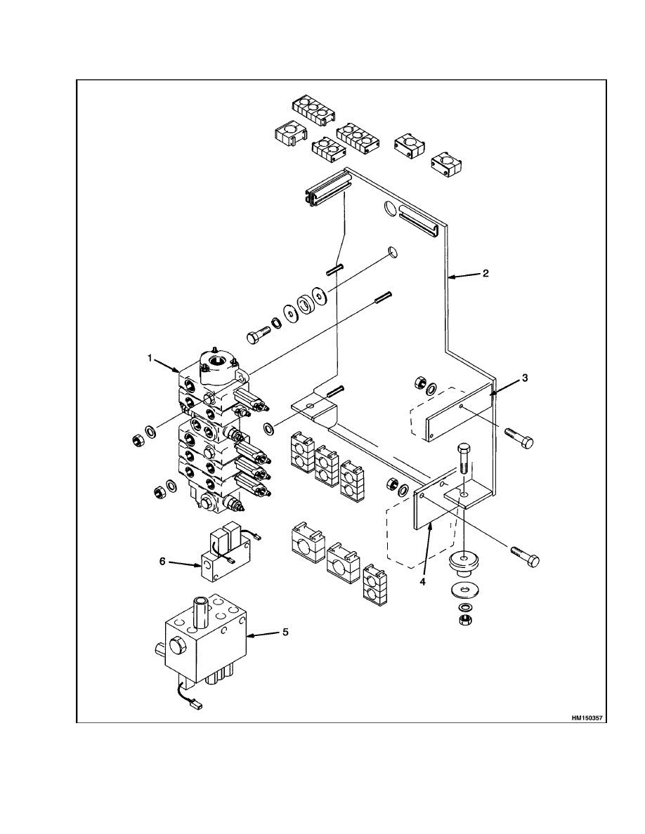
Figure 3. Hydraulic Module
7

Remote Control Valve Repair
1900 SRM 666
Legend for Figure 3
1.
MAIN CONTROL VALVE
2.
MODULE
3.
MOUNT FOR AUXILIARY CONTROL VALVE
4.
MOUNT FOR PILOT SUPPLY VALVE
5.
PILOT SUPPLY VALVE
6.
AUXILIARY CONTROL VALVE
CHECKS AND ADJUSTMENTS
Relief Pressures Check
1.
Connect a 28 MPa (4050 psi) gauge to the check
ports for control valve. See Table 1.
2.
Operate engine at 2100 rpm. When the oil tem-
perature is 54 to 65 C (130 to 150 F), check the
pressures as follows:
a. Operate lift spool to lift mast until it stops.
The hydraulic pressure will reach the relief
pressure at this point. The correct relief pres-
sure at check ports No. 1 and 2 in Table 1 is
23.8 to 24.5 MPa (3450 to 3550 psi) at full
throttle.
b. Operate tilt spool to tilt mast backward until
it stops. The hydraulic pressure will reach
the relief pressure at this point. The correct
relief pressure at check port No. 1 in Table 1
is 18.6 to 19.3 MPa (2700 to 2800 psi) at full
throttle.
3.
If the relief pressure is not correct, adjust relief
pressure as follows:
a. Remove cap.
b. Hold adjusting screw and loosen lock nut.
c.
Rotate adjusting screw to the left to lower the
relief pressure.
d. Rotate adjusting screw to the right to in-
crease the relief pressure.
e.
Tighten lock nut.
f.
Perform relief pressure check. If pressure
is not correct, repeat Step b, Step c, Step d,
and Step e until the correct relief pressure is
obtained.
g. Install cap.
Remote Control Valve Repair
DESCRIPTION
The remote control valve is installed in the console at
the right-hand side of the seat. The remote control
valve is an assembly of two sections with spools and
an intermediate block. One section controls the lift
and lower functions. The other section controls the
tilt function.
Each section of the remote control valve has two spool
assemblies that are actuated by a hand lever. The
spool assemblies in a section of the remote control
valve direct pilot oil flow to the spools in the main
control valve. Springs move the spools to close the
passages that supply pilot pressure when the opera-
tor releases the hand lever.
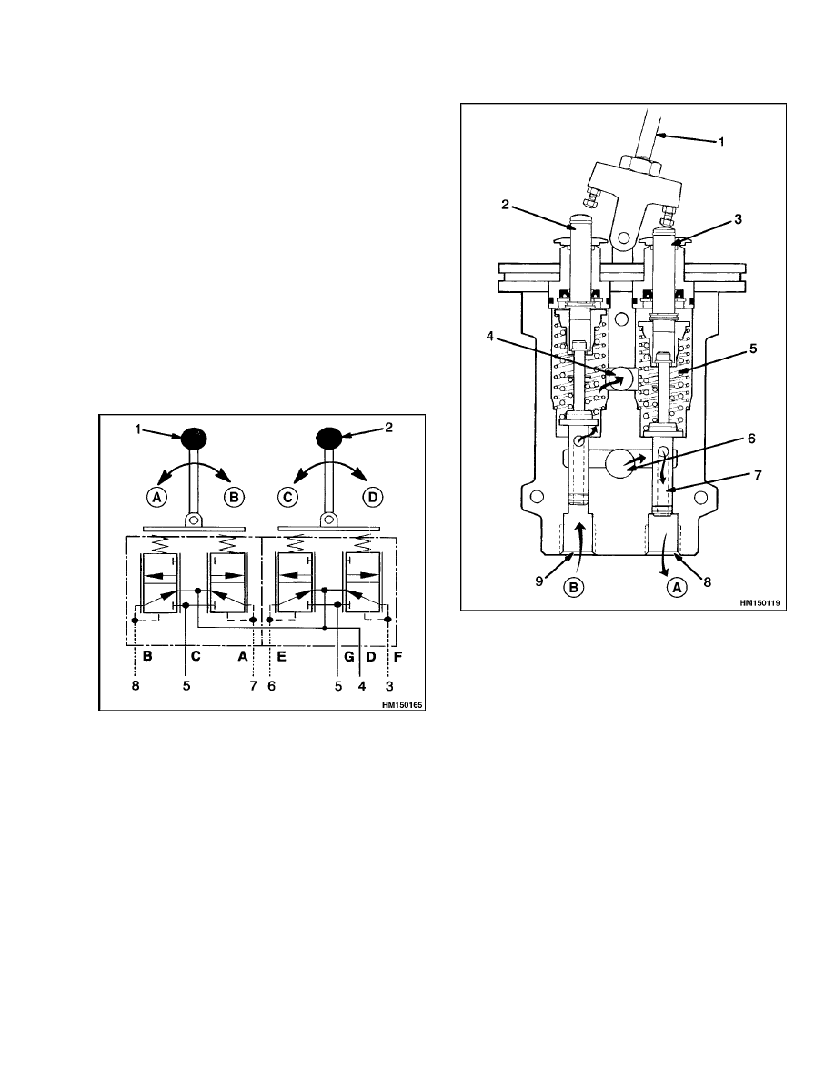
OPERATION
Through the use of pilot pressure, the remote con-
trol valves control the movement of the spools in the
main control valve. See Figure 4 and Figure 5. The
remote control valve assembly receives its oil supply
from the pilot supply valve at 2.8 to 3.2 MPa (400 to
450 psi).
In the NEUTRAL position, both spools in a remote
control valve are closed. They will not let the pilot
pressure flow to the main control valve. The spools
will, however, let the oil in the pilot lines flow to the
drain circuit.
When a control lever is moved forward or backward,
the control lever pushes on one of the plungers. The
plunger and guide push the springs and pilot spool
down. As the spool moves down, the passage in the
open-center spool allows oil flow from the inlet port
through the open center of the pilot spool to one of
the pilot lines. The pilot pressure pushes directly on
a spool in the main control valve. The oil in the op-
posite pilot line flows through the center of the spool
in the remote control valve and out of the drain port.
The movement of the spool(s) in the main control
valve is proportional to the movement of the spool
in the remote control valve. (The first 3 to 5 degrees
8
1900 SRM 666
Remote Control Valve Repair
of lever movement does not move the spool.) When
a hand lever is moved a small amount, the spool in
the remote control valve moves down and then closes.
The spool moves back up and closes because the pi-
lot circuit is full of oil and this pressure is sensed at
the bottom of the spool. The spool opens and closes
as necessary to keep the correct pressure in the pilot
circuit.
This action keeps the spool(s) in the main control
valve in the position selected by the operator. (The
spool can move down to let pressure in or it can move
up to open the pressure circuit to the drain circuit.)
When the control lever is released, the spool in a re-
mote control valve returns to the NEUTRAL posi-
tion. The pilot line is now open to the drain circuit.
This action permits the spool(s) in the main control
valve to return to NEUTRAL.
NOTE: LETTERS A - G ARE IDENTIFICATION
CODES.
A. DOWN
B. UP
C. FORWARD
D. BACK
1.
LIFT/LOWER
2.
TILT
3.
BACKWARD TILT
4.
DRAIN CIRCUIT
5.
SUPPLY
6.
FORWARD TILT
7.
LIFT
8.
LOWER
Figure 4. Remote Control Valve Schematic
B. NEUTRAL
A. ACTUATED
1.
CONTROL VALVE
LEVER
2.
PLUNGER,
NEUTRAL
POSITION
3.
PLUNGER,
ACTUATED
4.
DRAIN PORT
5.
SPRINGS
6.
INLET PORT
7.
PILOT SPOOL
8.
INLET PRESSURE
TO PILOT LINE
9.
PILOT LINE
PRESSURE TO
DRAIN
Figure 5. Remote Control Valve Operation
9
Remote Control Valve Repair
1900 SRM 666
REPAIRS
Remove
WARNING
When working on or near the mast, see Safety
Procedures When Working Near Mast in the
section Periodic Maintenance 8000 SRM 662.
1.
Lower mast completely. Shut off engine and ap-
ply parking brake.
WARNING
Before disconnecting any hydraulic lines, re-
lease pressure from the hydraulic circuit as fol-
lows:
a. Shut the engine off and completely lower
the carriage.
b. Operate the lift/lower lever and the brake
pedals until the hydraulic pressure is re-
leased.
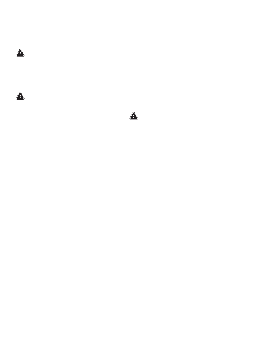
2.
Remove rear cover from console. See Figure 6.
Put identification tags on all hydraulic lines.
Disconnect hydraulic lines from remote control
valve. Put caps on open lines.
3.
Remove two screws that fasten cover that holds
remote control valve. Remove cover and valve as
a unit.
4.
Remove capscrews and nuts that fasten remote
control valve to cover. Remove cover from valve.
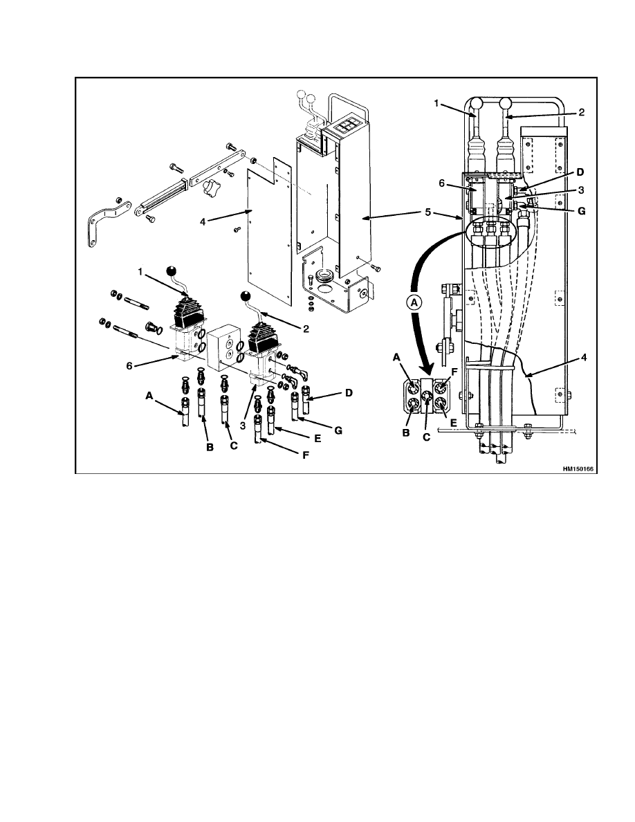
Disassemble
1.
Put identification marks on the sections of re-
mote control valve and intermediate block. See
Figure 7.
2.
Remove nuts and the through bolts that hold the
sections of valve together.
3.
Disassemble a valve section as follows:
a. Remove rubber boot from plate.
Remove
pivot pin for control lever. Remove control
lever and boot.
b. Put identification marks on valve body and
plates at the top of the valve body. Carefully
remove capscrews that hold plates to the top
of the valve body. Remove plates.
c.
Remove pin and guide assembly from valve
body.
WARNING
Compressed springs can release with great
force.
Wear eye protection and be careful
when disassembling valves.
d. Carefully remove spring assembly and spool
from the same bore in valve body. Remove
return spring.
NOTE:
Keep the parts from each bore separate. The
parts must be installed in the original bores. The
parts are adjusted with spacers. Make a note of the
number and location of the spacers. Changing the
spacers will affect the operation of the valve.
e.
Repeat Step c and Step d to remove the sec-
ond spool.
10
1900 SRM 666
Remote Control Valve Repair
NOTE: A = LIFT, B = LOWER, C = LIFT SUPPLY, D = DRAIN, E = TILT FORWARD, F = TILT BACKWARD, G = TILT
SUPPLY.
A. BOTTOM VIEW
1.
LIFT/LOWER LEVER
2.
TILT LEVER
3.
TILT PILOT VALVE
4.
COVER
5.
CONSOLE
6.
LIFT PILOT VALVE
Figure 6. Remote Control Valve Arrangement
11
Remote Control Valve Repair
1900 SRM 666
1.
PIN SET
2.
SPRING
3.
PLUG KIT
4.
SPRING
5.
SPACER
6.
PRESSURE PLATE
7.
PLATE
8.
LEVER
9.
KNOB
10. NUT
11. BOOT
12. VALVE BODY
Figure 7. Remote Control Valve
Clean and Inspect
WARNING
Cleaning solvents can be flammable and toxic
and can cause skin irritation.
When using
cleaning solvents, always follow the solvent
manufacturer’s recommended safety precau-
tions.
Compressed air can move particles so that they
cause injury to the user or to other personnel.
Make sure the compressed air path is away
from all personnel. Wear eye protection.
Clean all parts in solvent and dry parts with com-
pressed air. Inspect spools and bores for damage.
Inspect the parts of the valve assemblies for dam-
age. Replace damaged parts. If there are scratches
or other damage, the valve must be replaced. Spools
are not available as separate parts.
Assemble
1.
Install return springs in valve body. See Fig-
ure 7.
2.
Make sure that same spacers are used with each
spring assembly. Install spring assemblies and
12
1900 SRM 666
Pilot Supply Valve Repair
spools in bores. Make sure that parts are in-
stalled in the same bores from which they were
removed.
3.
Assemble guide and plunger assemblies. Install
O-rings and guides in valve body.
4.
Install plates at the top of valve. Tighten screws
to 5 N•m (44 lbf in). Install control lever and
rubber boot. If necessary, tighten lock nut on
hand lever to 30 N•m (22 lbf ft).
5.
Assemble valve sections and intermediate block.
Make sure O-rings are in position.
Install
through bolts. Tighten nuts to 5 N•m (44 lbf in).
Install
1.
Use capscrews and nuts to install console cover
on remote control valve. Make sure cover is in-
stalled in the correct direction.
2.
Install valve and cover as a unit. Fasten cover to
console with two screws.
3.
Connect hydraulic lines to the sections of valve
as shown in Figure 6.
4.
Start engine and operate hydraulic system.
Check that all functions of remote control valve
work correctly.
5.
If necessary, check pressure to remote control
valve. See Pressure Reduction Valves, Check in
this section for the correct procedure.
6.
Install back cover on console.
Adjust
When the hand lever is in the NEUTRAL position,
turn adjustment screw to get 0.13 to 0.25 mm (0.005
to 0.010 in.) clearance between the plunger and the
adjustment screw. See Figure 8. Tighten lock nut to
5 N•m (44 lbf in).
1.
PLUNGER
2.
ADJUSTMENT
SCREW
3.
LOCK NUT
Figure 8. Lever Adjustment
Pilot Supply Valve Repair
DESCRIPTION AND OPERATION
The pilot supply valve controls the flow of oil to
the circuits for the following: remote control valve,
brake system, and accumulator. See Figure 9 and
Figure 13.
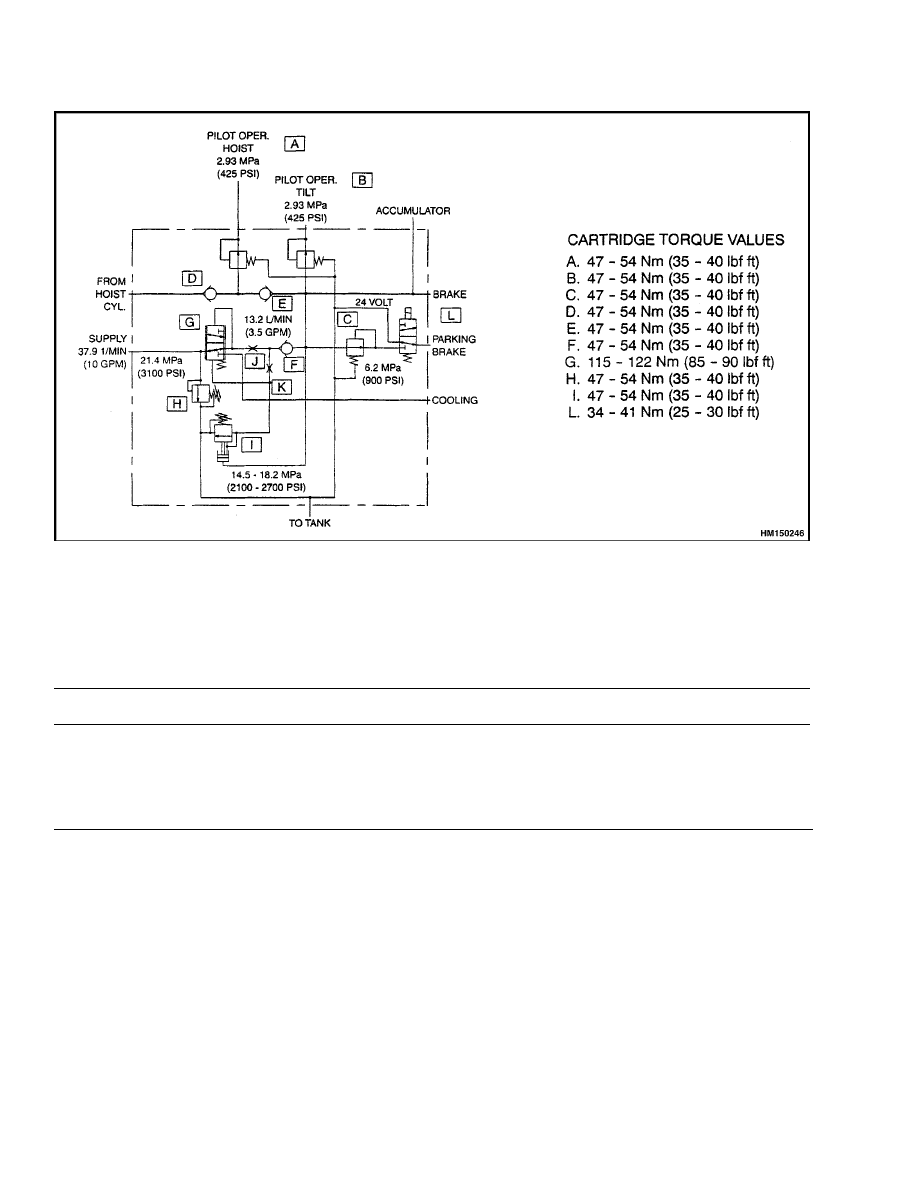
The pilot supply valve has a relief valve, three check
valves, a charging valve, an unloader valve, and
three pressure reduction valves. The solenoid that
operates the brake is also installed on the pilot
supply valve.
The relief valve limits the pressure from the hy-
draulic pump to 21.0 to 21.7 MPa (3050 to 3150 psi).
One check valve keeps oil in the parking brake cir-
cuit. The other check valves keep oil in the lift/lower
circuit at the remote control valve.
The pressure reduction valves control the oil pres-
sure to the remote control valves and the parking
brake system.
The circuit for the remote control
valves operates at 2.8 to 3.1 MPa (400 to 450 psi).
The parking brake circuit operates at 6.2 MPa
(900 psi).
The charging valve and unloader valve work together
to supply oil to the brake system and the accumu-
lator. The accumulator lets the operator apply the
brakes or lower the mast when the engine is not run-
ning.
The charging valve has a spool, check valve, and un-
loader valve. Oil from the pump enters the charging
valve spool. A relief valve limits this oil to 21.4 MPa
(3100 psi). Oil flows past the charging valve spool to
the accumulator and the pressure reduction valves.
13
Pilot Supply Valve Repair
1900 SRM 666
The charging valve stops charging automatically
when the accumulator pressure reaches its high
limit of 16.2 to 16.9 MPa (2350 to 2450 psi).
At
this time, all the oil flow goes to the oil cooler and
then to the brake system. When the accumulator
pressure reaches its low limit of 12.1 to 12.8 MPa
(1750 to 1850 psi), the unloader valve allows oil from
the pump to charge the accumulator.
Two check
valves in the circuit keep oil from flowing out of the
accumulator.
REPAIRS
WARNING
Compressed springs can release with great
force.
Wear eye protection and be careful
when disassembling valves.
Repairs to the pilot supply valve are limited to re-
placing seals and O-rings. See Figure 3 and Figure 9.
The relief valves and other parts must be replaced
as complete assemblies. Do not disassemble or try to
repair any of the cartridges. See Checks and Adjust-
ments to adjust the relief setting.
CHECKS AND ADJUSTMENTS
Relief Valve, Check and Adjust
1.
The relief valve(s) have a check port. Connect a
28 MPa (4050 psi) pressure gauge to the appro-
priate port. See Table 1.
2.
Start engine. Run engine until the temperature
of the hydraulic oil is 54 to 65 C (129 to 150 F).
For further details, see Table 1.
3.
To adjust a relief valve setting, remove cap. Use
an Allen wrench to turn adjuster screw. Turn ad-
juster screw clockwise to increase the pressure.
When the relief pressure is correct, install cap.
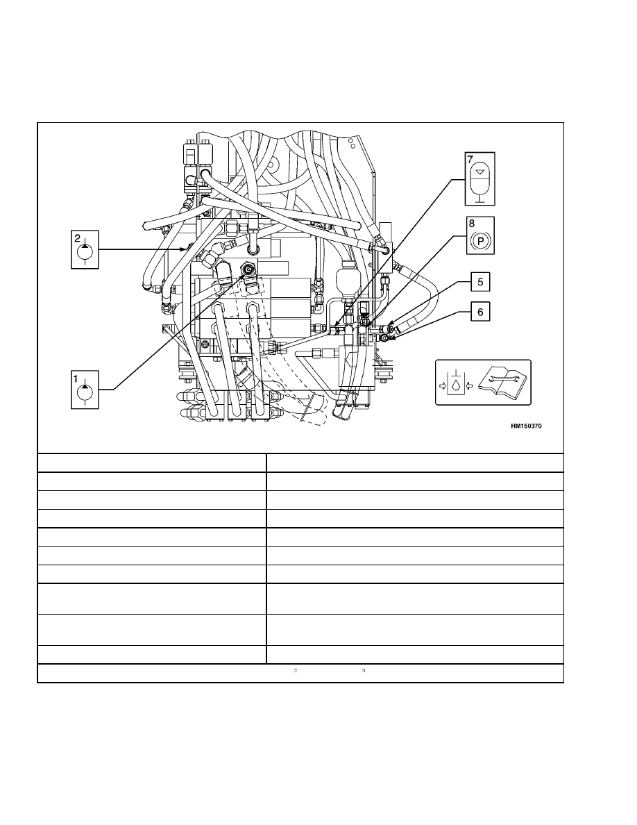
Pressure Reduction Valves, Check
Each pressure reduction valve has a check port. See
Figure 9 and Table 1. Check the pressures as follows:
1.
Lower lift cylinders completely. Connect a 4 MPa
(600 psi) gauge to check port Nos. 5 and 6 for the
2.8 to 3.1 MPa (400 to 450 psi) pressure reduc-
tion valves. Connect a 7 MPa (1000 psi) gauge to
check port No. 8 for the 6.0 to 6.4 MPa (875 to
925 psi) pressure reduction valve.
2.
Start engine and check pressure(s).
3.
To adjust the pressure setting, remove cap. Use
an Allen wrench to turn adjuster screw. Turn ad-
juster screw clockwise to increase the pressure.
When the relief pressure is correct, install cap.
14
1900 SRM 666
Pilot Supply Valve Repair
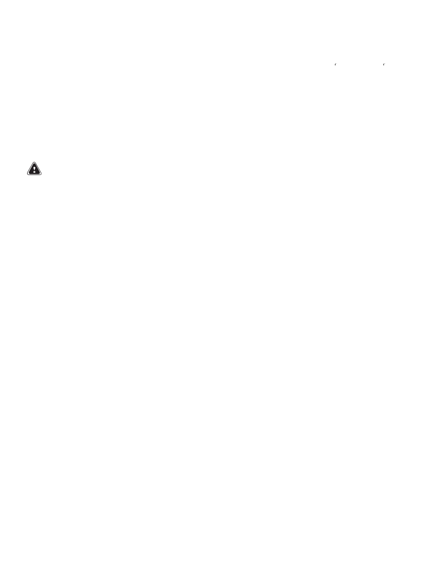
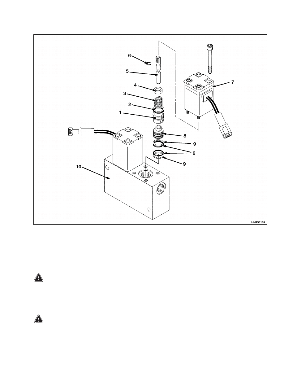
1.
PLUG
2.
BRAKE SYSTEM SUPPLY
3.
FROM LIFT CIRCUIT
4.
PILOT PRESSURE FOR TILT
5.
PILOT SUPPLY FOR
LIFT/LOWER
6.
RELIEF VALVE
7.
BRAKE SYSTEM COOLING
SUPPLY
8.
PARKING BRAKE SUPPLY
9.
CHARGING VALVE
10. PARKING BRAKE SOLENOID
11. UNLOADER VALVE
12. CHECK VALVE - LIFT
CYLINDER
13. CHECK VALVE - PARKING
BRAKE
14. CHECK VALVE - PILOT
SUPPLY
15. LIFT CIRCUIT - PRESSURE
REDUCTION VALVE
16. TILT CIRCUIT - PRESSURE
REDUCTION VALVE
17. PARKING BRAKE - PRESSURE
REDUCTION VALVE
Figure 9. Pilot Supply Valve
15
Auxiliary Control Valve Repair
1900 SRM 666
Auxiliary Control Valve Repair
DESCRIPTION AND OPERATION
The auxiliary control valve is a solenoid-operated
valve that controls the flow of oil from the auxiliary
spool in the main control valve. The operator actu-
ates the auxiliary control valve with switches in the
operator’s compartment. The oil from the auxiliary
control valve is used to move the auxiliary spool in
the main control valve. Oil from the auxiliary spool
flows to the selector valves for the functions at the
carriage, such as fork positioners.
When the operator pushes a switch, one solenoid on
the auxiliary control valve and a solenoid on the se-
lector valve are energized at the same time. The so-
lenoid on the auxiliary control valve opens and lets
oil flow through the pilot line to move the auxiliary
spool. The opposite end of the auxiliary spool is open
to drain through the other solenoid on the auxiliary
control valve. When the auxiliary spool moves, it lets
oil from the hydraulic pump flow to the selector valve
as required.
REPAIRS
Remove
1.
Stop engine and lower mast completely. Open
door for hydraulic module on left side of frame.
See Figure 3.
2.
Disconnect electrical wires at solenoid connec-
tors.
WARNING
Before disconnecting any hydraulic lines, re-
lease pressure from the hydraulic circuit as fol-
lows:
a. Shut the engine off and completely lower
the carriage.
b. Operate the lift/lower lever and the brake
pedals until the hydraulic pressure is re-
leased.
3.
Put identification tags on all hydraulic lines that
are connected to control valve. Disconnect lines
at fittings and put caps on open lines.
4.
Remove nuts, washers, and bolts that fasten con-
trol valve to plate.
Disassemble
WARNING
Compressed springs can release with great
force.
Wear eye protection and be careful
when disassembling valves.
1.
Make marks on each solenoid and valve body.
The marks are for alignment during assembly.
Remove capscrews and one of the solenoids. See
Figure 10.
2.
Remove the parts from valve body.
3.
Remove the other solenoid and parts.
16
1900 SRM 666
Auxiliary Control Valve Repair
1.
SPACER
2.
O-RING
3.
SPRING
4.
SPRING GUIDE
5.
SHUTTLE
6.
RETAINER
7.
SOLENOID
8.
SLEEVE
9.
BACKUP RING
10. VALVE BODY
Figure 10. Auxiliary Control Valve
Clean and Inspect
WARNING
Cleaning solvents can be flammable and toxic
and can cause skin irritation.
When using
cleaning solvents, always follow the solvent
manufacturer’s recommended safety precau-
tions.
WARNING
Compressed air can move particles so that they
cause injury to the user or to other personnel.
Make sure that the compressed air path is away
from all personnel. Wear eye protection.
Use solvent to clean metal parts. Carefully dry parts
with compressed air. Inspect bores for spools. In-
spect surfaces of spools that slide on bores. If a bore
or a spool has scratches or cracks, replace parts as
necessary.
Assemble
NOTE:
Lubricate parts with clean hydraulic oil and
install new seals during assembly.
17

Hydraulic Pump Repair
1900 SRM 666
1.
Install O-rings and backup rings on sleeve. See
Figure 10. Install O-ring on spacer. Install sleeve
in body. Install spring retainer, spring, cover,
and capscrews. Push the other end of the spool
so spool moves in bore. If spool does not move
freely, replace direction control valve.
2.
Install spacer, spring, and spring guide. Install
retainer on shuttle. Install shuttle.
3.
Install solenoid and capscrews.
Install
1.
Install control valve on plate. See Figure 3.
2.
Connect hydraulic lines.
Connect wires to
solenoids.
Check and Adjust
The auxiliary control valve has no adjustments. See
Pilot Supply Valve Repair, Checks and Adjustments
in this section to check the pilot pressure.
Hydraulic Pump Repair
GENERAL
The hydraulic pump is a three-section gear pump
that is driven by a power takeoff arrangement on the
transmission housing. The inlet hose for each pump
section is connected to the hydraulic tank. The three
sections of the pump supply different parts of the hy-
draulic system. The smallest section of the pump
supplies oil to the pilot supply valve. The middle sec-
tion of the pump supplies oil to the main control valve
for the lift, tilt, and auxiliary circuits. The large sec-
tion of the pump supplies oil to a steering priority
valve in the main control valve.
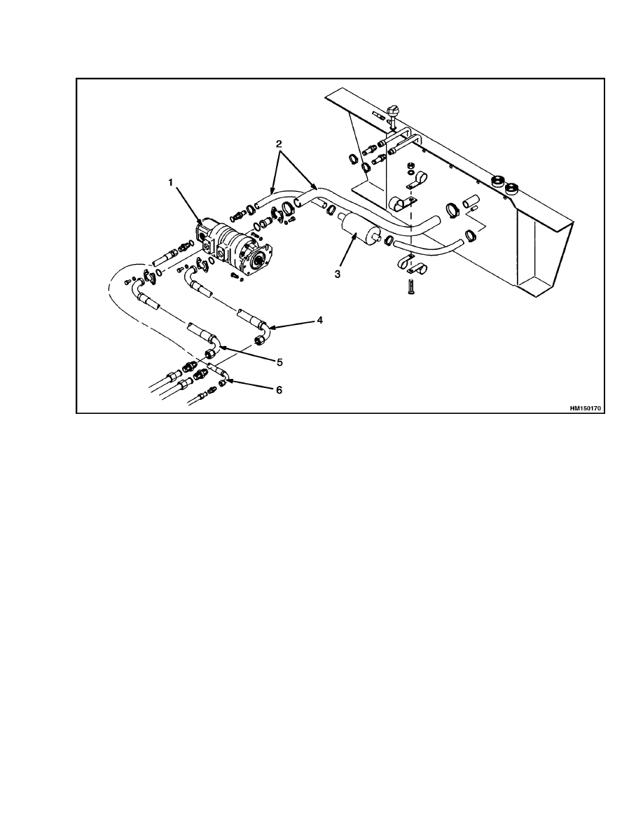
REPAIRS
Repair information for the pump is in the section Hy-
draulic Gear Pumps 1900 SRM 97. See Figure 11
when removing or installing the pump.
18
1900 SRM 666
Hydraulic Pump Repair
1.
HYDRAULIC PUMP
2.
SUCTION LINE
3.
FILTER
4.
TO MAIN CONTROL VALVE
5.
TO MAIN CONTROL VALVE
6.
TO PILOT SUPPLY VALVE
Figure 11. Hydraulic Pump Arrangement
19
Specifications
1900 SRM 666
Specifications
Table 1. Hydraulic System Check Ports
Label for Hydraulic System Check Ports
Check Port
Specification
No. 1 - Lift System Relief
23.8 to 24.5 MPa (3450 to 3550 psi)@ full throttle
No. 1 - Tilt/Aux System Relief
18.6 to 19.3 MPa (2700 to 2800 psi)@ full throttle
No. 2 - Lift System Relief
23.8 to 24.5 MPa (3450 to 3550 psi)@ full throttle
No. 2 - Steering System Relief
16.2 to 16.9 MPa (2350 to 2450 psi) @ full throttle
No. 5 - Lift System Pilot Pressure
2.8 to 3.1 MPa (400 to 450 psi) @ idle speed
No. 6 - Tilt/Auxiliary Pilot Pressure
2.8 to 3.1 MPa (400 to 450 psi) @ idle speed
No. 7 - Accumulator Charge Valve (Low)
Pressure
12.1 to 12.8 MPa (1750 to 1850 psi) @ idle speed
No. 7 - Accumulator Charge Valve (High)
Pressure
16.2 to 16.9 MPa (2350 to 2450 psi) @ idle speed
No. 8 - Parking Brake Pressure
6.0 to 6.6 MPa (875 to 925 psi) @ idle speed
Make sure oil is at operating temperature - 54 to 65 C (129 to 150 F).
20

NOTES
____________________________________________________________
____________________________________________________________
____________________________________________________________
____________________________________________________________
____________________________________________________________
____________________________________________________________
____________________________________________________________
____________________________________________________________
____________________________________________________________
____________________________________________________________
____________________________________________________________
____________________________________________________________
____________________________________________________________
____________________________________________________________
____________________________________________________________
____________________________________________________________
____________________________________________________________
____________________________________________________________
____________________________________________________________
____________________________________________________________
21
Schematics
1900 SRM 666
22
1900 SRM 666
Schematics
Figure 12. Hydraulic System Schematic (Sheet 1 of 3)
23
Schematics
1900 SRM 666
24
1900 SRM 666
Schematics
Figure 12. Hydraulic System Schematic (Sheet 2 of 3)
25
Schematics
1900 SRM 666
26
1900 SRM 666
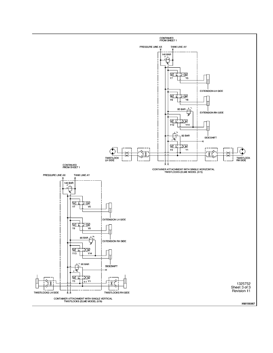
Schematics
Figure 12. Hydraulic System Schematic (Sheet 3 of 3)
27
Troubleshooting
1900 SRM 666
Figure 13. Pilot Supply Valve Cartridge Torque Values
Troubleshooting
MAIN CONTROL VALVE
PROBLEM
POSSIBLE CAUSE
PROCEDURE OR ACTION
Oil leaks from end of spool.
O-rings at spool housing(s) leak.
Install new O-rings.
Retainers for spool housing are loose.
Tighten capscrews for retainers.
Pilot lines are damaged or leak.
Tighten fittings or install new lines.
Spool(s) will not move.
The pressure from the remote control
valve is not correct.
Check pilot pressure. Make repairs
as necessary.
Remote control valve is damaged.
Repair control valve.
Pressure reduction valve for pilot
supply is damaged or not adjusted
correctly.
Repair or adjust.
Pilot lines are damaged or leak.
Tighten fittings or install new lines.
Spool does not move freely in bore.
Repair valve section.
28
1900 SRM 666
Troubleshooting
PROBLEM
POSSIBLE CAUSE
PROCEDURE OR ACTION
Spool(s)
will
not
move.
(Cont.)
Spool will not return to the
NEUTRAL position.
Return spring or springs are dam-
aged. Capscrew for spring is loose.
Install new spring and tighten cap-
screw.
Spool does not move freely in bore.
Install new valve section.
Slow or no movement of lift
cylinder(s).
Relief valve(s) is damaged or not cor-
rectly adjusted.
Check and adjust pressure. Install
new relief valve.
Leaks between spool(s) and bore(s).
Install new valve section.
Spool(s) not fully extended or re-
tracted.
Check that spool moves freely in
bore.
Hydraulic pump is damaged.
Repair pump.
Restriction in the hydraulic lines.
Check and repair hydraulic lines.
Load is greater than capacity of the
system.
Handle correct loads.
Damaged load check valve(s).
Install new check valve(s).
The pressure from the remote control
valve is not correct.
Check pilot pressure. Make repairs
as necessary.
Hydraulic pressure is above
or below specifications.
Relief valve is damaged.
Check and adjust pressure. Install
new relief valve.
Restriction in the return line.
Check and repair hydraulic lines.
REMOTE CONTROL VALVE
PROBLEM
POSSIBLE CAUSE
PROCEDURE OR ACTION
The cylinders that are con-
trolled by the remote control
valve do not move, or move
slowly.
A spool or spools in the remote con-
trol valve do not move completely.
Check and repair valve as necessary.
Pilot pressure from the pilot supply
valve is not correct.
Check pressure from pilot supply
valve.
The pilot lines are damaged or have
leaks.
Install new pilot lines.
29
Troubleshooting
1900 SRM 666
PROBLEM
POSSIBLE CAUSE
PROCEDURE OR ACTION
The cylinders that are con-
trolled by the remote control
valve do not move, or move
slowly. (Cont.)
PILOT SUPPLY VALVE
PROBLEM
POSSIBLE CAUSE
PROCEDURE OR ACTION
ACCUMULATOR CHARGE VALVE AND ACCUMULATOR
Remote control valve does
not operate correctly.
Accumulator charge valve does not
operate correctly.
Check pilot pressure at check ports.
Restriction in line to pilot supply
valve.
Install new line.
Carriage/attachment
func-
tions do not operate.
Accumulator charge valve does not
operate correctly.
Clean or replace charge valve.
Electrical wires are damaged or dis-
connected.
Connect or repair wires.
Pressure reduction valve is not ad-
justed correctly.
Check and adjust pressure.
Mast does not lower when
the engine is not running.
Accumulator does not operate cor-
rectly.
Replace accumulator.
Accumulator charge valve does not
operate correctly.
Clean or replace charge valve.
PRESSURE REDUCTION VALVES
Remote control valve does
not operate correctly.
Pressure reduction valve is not ad-
justed correctly.
Check pilot pressure at check ports.
Hydraulic line(s) has a restriction.
Install new line.
Accumulator charge valve does not
operate correctly.
Clean or replace charge valve.
Electrical wires are damaged or dis-
connected.
Connect or repair wires.
30
1900 SRM 666
Troubleshooting
PROBLEM
POSSIBLE CAUSE
PROCEDURE OR ACTION
Remote control valve does
not operate correctly. (Cont.)
Carriage/attachment
func-
tions do not operate.
Pressure reduction valve is not ad-
justed correctly.
Check and adjust pressure.
Hydraulic line(s) has a restriction.
Install new line.
Parking brake will not re-
lease.
Pressure reduction valve is not ad-
justed correctly.
Check and adjust pressure.
Hydraulic line(s) has a restriction.
Install new line.
Accumulator charge valve does not
operate correctly.
Clean or replace charge valve.
AUXILIARY CONTROL VALVE
PROBLEM
POSSIBLE CAUSE
PROCEDURE OR ACTION
An auxiliary function does
not operate.
The switch for the function does not
operate correctly.
Check and repair switch or wiring.
Solenoid does operate correctly.
Replace solenoid.
Pilot pressure is not correct.
Check and adjust pressure.
The accumulator charge valve does
not operate correctly.
Repair or replace accumulator.
The pump is damaged.
Repair pump.
The lines from the main control valve
to the selector valves have damage.
Repair lines.
Selector valve(s) does not operate
correctly.
Check and repair valve.
All auxiliary functions have
reverse operation.
The lines from the attachment con-
trol valve are incorrectly connected
at the manifold for selector valves.
Connect lines correctly.
One auxiliary function has
reverse operation.
The switch is incorrectly connected
to the solenoids on the pilot valve.
Check wiring.
31

NOTES
____________________________________________________________
____________________________________________________________
____________________________________________________________
____________________________________________________________
____________________________________________________________
____________________________________________________________
____________________________________________________________
____________________________________________________________
____________________________________________________________
____________________________________________________________
____________________________________________________________
____________________________________________________________
____________________________________________________________
____________________________________________________________
____________________________________________________________
____________________________________________________________
____________________________________________________________
____________________________________________________________
____________________________________________________________
____________________________________________________________
32

TECHNICAL PUBLICATIONS
1900 SRM 666
9/02 (5/01)(5/97) Printed in United Kingdom
Document Outline
- toc
- tables
Wyszukiwarka
Podobne podstrony:
897394 1900SRM0453 (09 2003) UK EN
897110 1900SRM0328 (09 2003) UK EN
1466223 1900SRM0753 (09 2003) UK EN
1564283 1900SRM1107 (01 2004) UK EN
910091 1900SRM0097 (08 2005) UK EN
1598459 1900SRM1213 (03 2005) UK EN
1494953 1400SRM0944 (09 2003) UK EN
1452930 8000SRM0680 (12 2002) UK EN
897956 1900SRM0642 (03 2005) UK EN
1526432 8000SRM1041 (07 2002) UK EN
1470232 1900SRM0783 (01 2004) UK EN
897066 0100SRM0284 (10 2002) UK EN
1498445 1400SRM0945 (09 2003) UK EN
910092 1900SRM0098 (07 2003) UK EN
1510463 1400SRM0984 (09 2003) UK EN
więcej podobnych podstron