
IPN
X
M
EDIA
G
ATEWAY
D
EC
04
Version 1.0
December 2004 Page 1 of 28
©
W
ORLD TELECOM
L
ABS
C h a n g i n g t h e W a y t h e W o r l d C o m m u n i c a t e s
I P N x S i g n a l l i n g & M e d i a
G a t e w a y
T e c h n i c a l D a t a

IPN
X
M
EDIA
G
ATEWAY
D
EC
04
Version 1.0
December 2004 Page 2 of 28
©
W
ORLD TELECOM
L
ABS
1
Introduction....................................................................................................................................... 4
2
C7 / SS7 ........................................................................................................................................... 4
2.1
Protocols supported .................................................................................................................. 4
2.2
Distributed signalling ................................................................................................................. 4
2.3
Number of point codes supported............................................................................................. 4
2.4
Multiple signalling protocols ...................................................................................................... 4
2.5
Scalability .................................................................................................................................. 5
2.6
Bearer capabilities..................................................................................................................... 5
2.7
Licensing ................................................................................................................................... 5
2.8
C7 / SS7 approvals ................................................................................................................... 6
2.9
C7 / SS7 interconnect ............................................................................................................... 6
2.10
DDI numbers ......................................................................................................................... 8
2.11
Indirect access....................................................................................................................... 8
2.12
Carrier pre-selection.............................................................................................................. 8
3
VoIP.................................................................................................................................................. 9
3.1
Protocols supported .................................................................................................................. 9
3.2
Multiple signalling protocols .................................................................................................... 10
3.3
Scalability ................................................................................................................................ 10
3.4
Voice and video CODEC’s supported..................................................................................... 10
3.5
Fax & Modem over IP support ................................................................................................ 10
3.6
Licensing ................................................................................................................................. 11
3.7
VoIP interconnect.................................................................................................................... 11
4
Call routing ..................................................................................................................................... 11
5
Protocol support ............................................................................................................................. 12
5.1
Protocols supported other than C7 / SS7 and VoIP protocols................................................ 12
5.2
Inter-working of TDM to TDM protocols.................................................................................. 12
5.3
Inter-working of VoIP to VoIP protocols.................................................................................. 12
5.4
Inter-working of TDM to VoIP / VoIP to TDM protocols .......................................................... 12
5.5
Inter-working with other vendors............................................................................................. 12
6
Supplementary services................................................................................................................. 12
6.1
TDM supplementary services supported ................................................................................ 12
6.2
VoIP supplementary services supported ................................................................................ 13
6.3
Inter-working of supplementary services on TDM to TDM protocols...................................... 13
6.4
Inter-working of supplementary services on VoIP to VoIP protocols...................................... 14
6.5
Inter-working of supplementary services on TDM to VoIP / VoIP to TDM protocols .............. 14
6.6
Inter-working with other vendors............................................................................................. 14
7
Features and services.................................................................................................................... 14
7.1
IP voice VPN ........................................................................................................................... 14
7.2
TDM voice VPN....................................................................................................................... 14
7.3
Number translation services ................................................................................................... 15
7.4
Local Number portability ......................................................................................................... 15
7.5
Number portability................................................................................................................... 15
7.6
Emergency services................................................................................................................ 15
7.7
Legal intercept......................................................................................................................... 15
7.8
Voicemail / Unified messaging................................................................................................ 15
7.9
Network ACD .......................................................................................................................... 15
7.10
Contact centre solutions...................................................................................................... 16
7.11
IVR....................................................................................................................................... 16
7.12
Voice conferencing.............................................................................................................. 16
7.13
Video conferencing.............................................................................................................. 16
7.14
Multipoint Control Unit (MCU) / Bridging ............................................................................. 16
7.15
Outbound calling.................................................................................................................. 16
7.16
Text to speech / Speech to text........................................................................................... 16
7.17
Voice XML ........................................................................................................................... 17
7.18
API’s & programming interfaces.......................................................................................... 17
7.19
Other applications and services .......................................................................................... 17
8
System architecture........................................................................................................................ 17
8.1
System architecture ................................................................................................................ 17
8.2
Operating system .................................................................................................................... 18
9
Quality of service............................................................................................................................ 18

IPN
X
M
EDIA
G
ATEWAY
D
EC
04
Version 1.0
December 2004 Page 3 of 28
©
W
ORLD TELECOM
L
ABS
10
Security....................................................................................................................................... 19
10.1
Call verification and authorisation ....................................................................................... 19
10.2
Encryption of the VoIP signalling messages ....................................................................... 19
10.3
Encryption of the VoIP media stream.................................................................................. 19
10.4
Unauthorised access........................................................................................................... 19
11
Scalability.................................................................................................................................... 19
11.1
Call processing scalability for softswitch ............................................................................. 19
11.2
Applications scalability ........................................................................................................ 20
12
Reliability .................................................................................................................................... 20
13
Approvals.................................................................................................................................... 20
14
Billing .......................................................................................................................................... 20
14.1
Customer billing................................................................................................................... 20
14.2
Interconnect billing for C7 / SS7.......................................................................................... 27
14.3
Interconnect billing for VoIP ................................................................................................ 27
15
Fraud detection........................................................................................................................... 27
16
Operations and support .............................................................................................................. 27
16.1
Management system ........................................................................................................... 27

IPN
X
M
EDIA
G
ATEWAY
D
EC
04
Version 1.0
December 2004 Page 4 of 28
©
W
ORLD TELECOM
L
ABS
1 Introduction
The IPNx switch provides a range of integrated communications services including TDM voice,
VoIP, Calling Card, voice VPNs, call routing and billing. The importance of the IPNx as a media &
signalling gateway between C7 / SS7 networks and the IP world is growing.
Solutions based on ISDN E1 signalling work for the simple termination of voice traffic but present
limitations in terms of the PSTN supplementary services that can be passed from the customer
network to the carriers’ networks. Even with wholesale agreements in place the rates offered to
service providers connecting to carriers using ISDN PRI’s are generally higher than those rates
offered when the service provider can connect using C7 / SS7. Also when connecting to
incumbent operators (such as B.T. in the UK) C7 / SS7 becomes a necessity to achieve any kind
of wholesale rates or to provide services such as indirect access / carrier selection.
2 C7 / SS7
2.1 Protocols supported
Which variants of C7 / SS7 and which versions of these variants does the proposed product
support? Please state and describe any functional limitations associated with their implementation
of each of the supported variants.
MTP layer
The IPNX is conformant to ITU Q704 specification.
ISUP layer
The IPNX is conformant to ITU-T Q763 and Q764 1992 version. The IPNx supports ETSI ISUP as
the core signalling and different country or carrier variants are controlled by parameters on the
core.
No functional limitations are known.
2.2 Distributed signalling
Please state if it is possible for the system to be split into two physically separate nodes which will,
when connected via an IP network, act as a single redundant system. If this is possible state if it is
possible for this geographically split system to have node A handle one signalling link from an
interconnect which uses two signalling links and four node B to handle the second signalling link. If
the proposed solution is capable of such functionality vendors should describe any problems or
difficulties, if any, that their products have when installed and configured in such a way.
It is possible to configure the IPNx to run in a redundant manner as described here.
IPNx A will handle one of the signalling links from a carrier and IPNx B will handle the other.
These 2 nodes may be geographically separate. They must be connected by a reliable IP network.
The A and B nodes will operate in a load sharing fashion rather than having one node operational
and the other in standby mode.
2.3 Number of point codes supported
Please state the number of national and (if applicable to the variant) international point codes
supported for each C7 / SS7 variant. Please also state and describe any factors, if any, which will
reduce the number of point codes supported. I.e. the number of point codes supported is reduced
for all protocols if a specific C7 / SS7 variant is enabled, etc.
The maximum number of destination point codes supported is 128. The maximum number of
local point codes supported is currently 2. This could be increased to 8 if required. The
maximum number of point codes is unaffected by factors such as choice of signalling variant.
2.4 Multiple signalling protocols
Please state if the proposed product is able to operate using different C7 / SS7 variants at the
same time. Also state if there is a limit on the number of C7 / SS7 variants that can be utilised at
the same time or if it is possible for each signalling link or at least each pair of signalling links to
be configured with a different C7 / SS7 variant at the same time.

IPN
X
M
EDIA
G
ATEWAY
D
EC
04
Version 1.0
December 2004 Page 5 of 28
©
W
ORLD TELECOM
L
ABS
There is no limit on the different SS7 variants which can be used at the same time.
2.5 Scalability
Please provide clear answers to the following:
Busy Hour Call Attempts (BHCA) supported by a redundant system.
BHCA supported is 300,000
Maximum number of signalling links a) per single switch and b) per single redundant system.
a.
56 signalling links is the maximum number per single chassis
b.
112 signalling links is the maximum number per single redundant system
Maximum number of signalling links per interconnect.
The maximum number of signalling links per interconnect is 16 (as in SS7 standards).
Maximum number of M.S.U.’s supported by a single redundant system.
A single redundant system can support up to 8000 MSUs per second.
Maximum number of sustained calls for a single redundant system.
Maximum number of sustained calls per single chassis is 1,680. This means all 56 E1s are fully
active.
Maximum number of sustained calls is 3,360. This means all 112 E1s are fully active.
Maximum number of E1’s supported by a single redundant system.
112 E1’s supported by a single redundant system.
Note: All of the answers in 7.5 assume that a single redundant system is made up of a
redundant pair of IPNx switches, each capable of supporting up to 56 E1 ports (therefore, 112
for the redundant system). However, these redundant pairs can in turn be combined to create
switches up to 2048 E1s. Since this means adding new switches with their own processing then
all of the above values increase in a linear fashion.
2.6 Bearer capabilities
Please list the bearer capabilities that the C7 / SS7 solution supports. Also list what bearer
capability can be mapped from C7 / SS7 to the other protocols supported by the solution. For
example can a call with a 64K UDI bearer capability / Telephony Media Request (TMR) be
mapped to an H.323 call using the proposed solution. Also list what bearer capabilities can be
mapped from other protocols to the C7 / SS7 side using the proposed solution.
Supported Capabilities
Function/service
IPNX
Basic call
Speech
Y
3.1 kHz audio
Y
64 kbit/s unrestricted
Y
The above bearer capabilities can be mapped to all other signalling protocols. It is also
possible to override requested capabilities (for example these are often wrongly formatted by
H323 equipment).
2.7 Licensing
Please clearly state if a license fee, in addition to any hardware or software costs, is associated
with any part of the C7 / SS7 solution. For example does a signalling link card require a license
to be purchased before that card can be used (either used practically or legally).
IPN
X
M
EDIA
G
ATEWAY
D
EC
04
Version 1.0
December 2004 Page 6 of 28
©
W
ORLD TELECOM
L
ABS
Every E1 port that carries a SS7 signalling link must be licensed. The list price of this license is
€2400
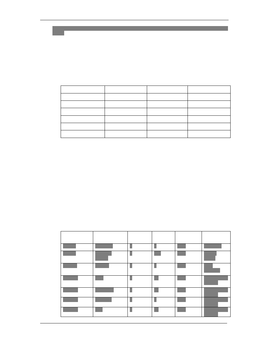
2.8 C7 / SS7 approvals
Clearly state the C7 / SS7 approvals that the product has achieved. This explanation should
clearly show the organisation granting the approval, the country that the approval applies to, the
date of the approval and the C7 / SS7 variant(s) and version(s) that that approval applies to. It
should also be clearly stated if the approvals granted apply to all current and future software
levels on the C7 / SS7 solution or if any of the approvals will cease as software levels increase.
If any of the approvals expire after a specific date this date(s) should be clearly shown.
Organisation
Country
Date
Software Version
BT
UK
2002
TXISUP V1.36
Belgacom
Belgium
1999
TXISUP V1.24
KPN
Holland
2001
TXISUP V1.33
TeleDenmark
Denmark
2000
TXISUP V1.29
Telefonica
Spain
2000
TXISUP V1.30
PTT Austria
Austria
1999
TXISUP V1.26
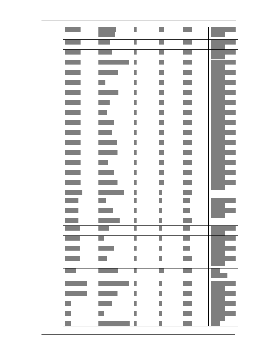
2.9 C7 / SS7 interconnect
Clearly state the number of C7 / SS7 interconnects and with which variant and version this
interconnect took place that their product has passed. Vendors should also state the following
for each interconnect:
a) Country that interconnect took place.
b) Carrier interconnected too.
c) Number of signalling links used.
d) Number of E1 bearers used.
e) Traffic loading in terms of calls per second (CPS) and Erlangs or
minutes per month after the interconnect had been completed and
had gone live.
f) If traffic was incoming, outgoing or both.
g) Main use of interconnect I.e. terminating traffic, indirect access, etc.
Country
Carrier
Signalling
Links
E1
Bearers
Traffic (In,
Out, Both)
Main Use
Austria
Mobilkom
2
4
Both
Call Back
Austria
TeleKom
Austria
2
300
Both
Carrier
Select
Bahrain
Batelco
2
4
Both
VoIP
Trunking
Belgium
B3G
2
10
Both
Least Cost
Routing
Belgium
Belgacom
2
20
Both
Least Cost
Routing
Belgium
BT Ignite
2
8
Both
Least Cost
Routing
Belgium
Colt
2
30
Both
Least Cost
Routing
IPN
X
M
EDIA
G
ATEWAY
D
EC
04
Version 1.0
December 2004 Page 7 of 28
©
W
ORLD TELECOM
L
ABS
Belgium
Deutsche
Telekom
2
20
Both
Least Cost
Routing
Belgium
EADS
2
10
Both
Least Cost
Routing
Belgium
Enertel
2
20
Both
Least Cost
Routing
Belgium
France Telecom 2
60
Both
Least Cost
Routing
Belgium
Global UK
2
24
Both
Least Cost
Routing
Belgium
IDT
2
30
Both
Least Cost
Routing
Belgium
InterRoute
2
50
Both
Least Cost
Routing
Belgium
Kedra
2
30
Both
Least Cost
Routing
Belgium
KPN
2
40
Both
Least Cost
Routing
Belgium
LD Com
2
16
Both
Least Cost
Routing
Belgium
Primus
2
24
Both
Least Cost
Routing
Belgium
RSL Com
2
30
Both
Least Cost
Routing
Belgium
Swisscom
2
24
Both
Least Cost
Routing
Belgium
Telia
2
20
Both
Least Cost
Routing
Belgium
Versatel
2
80
Both
Least Cost
Routing
Belgium
Worldcom
2
60
Both
Least Cost
Routing
Denmark
TeleDenmark
2
2
Both
France
Colt
2
4
Out
Least Cost
Routing
France
Intercall
2
2
Out
Least Cost
Routing
France
WaveCrest
2
8
Both
Holland
AT&T
2
2
Out
Least Cost
Routing
Holland
BT
2
2
Out
Least Cost
Routing
Holland
Carrier1
2
2
Out
Least Cost
Routing
Holland
KPN
2
8
Both
Least Cost
Routing
Spain
Telefonica
2
60
Both
VoIP
Trunking
Switzerland
Global Crossing 2
4
Both
Least Cost
Routing
Switzerland
Swisscom
2
4
Both
Least Cost
Routing
UK
Arbinet
2
4
Both
Least Cost
Routing
UK
BT
2
4
Both
Least Cost
Routing
UK
Cable
& 2
4
Both
VoIP

IPN
X
M
EDIA
G
ATEWAY
D
EC
04
Version 1.0
December 2004 Page 8 of 28
©
W
ORLD TELECOM
L
ABS
Wireless
Trunking
UK
Energis
2
2
Both
Least Cost
Routing
UK
Global Crossing 2
2
Both
Least Cost
Routing
UK
Swisscom
2
2
Both
Least Cost
Routing
UK
Telecom New
Zealand
2
2
Both
Least Cost
Routing
UK
Worldcom
2
4
Both
Least Cost
Routing
2.10 DDI numbers
Clearly state if the proposed C7 / SS7 solution has the ability to route incoming DDI numbers to
the correct CPE customer. State any limitations with regards to this functionality. I.e. depends
on C7 / SS7 variant, depends if routing to a VoIP protocol or ISDN PRI port on the C7 / SS7
gateway, can route to H.323 devices but not to SIP devices, etc.
The IPNx can route incoming DDI numbers based on part or all of the DDI number. The called
number may also be modified if required. Calls may be routed to ISDN PRI ports or to individual
IP addresses. No limitations exist on the use of this function. There is no distinction made
between H323 and SIP.
2.11 Indirect access
Clearly state if the proposed solution supports an indirect access (IDA) service. Describe the
basic operation of this service.
Also describe any additional software and / or hardware that is required to enable IDA on the
product. Any licensing requirements should also be clearly stated and explained.
State if the IDA implementation allows full C7 / SS7 signalling transparency (so far as any
differences between the incoming C7 / SS7 variant and the outgoing C7 / SS7 variant allow).
IDA is supported as a standard feature of the IPNx. No additional hardware or licensing is
required to enable it. This may be by 2 stage dialling or by carrier select codes. Number
translation features are available which give great flexibility in the case of carrier select. Carrier
select codes may be stripped or inserted as required.
The IPNx is a fully functional telecom switch. Calls are routed in the most efficient way
regardless of traffic type. Therefore, calls will be routed directly from one SS7 carrier to another
with complete signalling transparency.
2.12 Carrier pre-selection
Clearly state if the proposed solution supports a Carrier Pre-Select (CPS) service (the ability for
the platform to receive and correctly handle CPS calls from subscribers (passed via an
intermediate network) using CPS). Describe the basic operation of this service on the product.
For example, do all CPS calls (excluding those actually destined for a directly connected
customer) pass through the C7 / SS7 TDM solution only or is the call routed from the C7 / SS7
solution to the IP network and back to the C7 / SS7 side.
Also describe any additional software and / or hardware that is required to enable CPS on their
product. Any licensing requirements should also be clearly stated and explained.
State if the CPS implementation allows full C7 / SS7 signalling transparency (so far as any
differences between the incoming C7 / SS7 variant and the outgoing C7 / SS7 variant allow).
CPS is supported as a standard feature of the IPNx. No additional hardware or licensing is
required to enable it.

IPN
X
M
EDIA
G
ATEWAY
D
EC
04
Version 1.0
December 2004 Page 9 of 28
©
W
ORLD TELECOM
L
ABS
The IPNx is a fully functional telecom switch. Calls are routed in the most efficient way
regardless of traffic type. Therefore, CPS calls will be routed directly from one SS7 carrier to
another with complete signalling transparency.
3 VoIP
3.1 Protocols supported
Which VoIP protocols and which versions of these protocols does the proposed product support
(signalling transport mechanisms / protocols such as SIP-T & Sigtran / SCTP should be
included here)? Vendors should state and describe any functional limitations associated with
their implementation of each of the supported variants.
The IPNx supports SIP and H323 Versions 1, 2, 3 and 4.
The following components of H323 are supported:
H225 version 4 including the following features:
multiple calls per call signalling channel
separate H245 connection
fast start
early H245 connection
tunneling of H245 and fallback to separate connection procedure if the peer does not
support tunneling
enbloc/overlap sending/receiving
SS7/Q931 mapping of the following information elements:
o
called party number
o
calling party number
o
progress indicator
o
bearer capability
o
user to user information
o
called subaddress
o
cause value
o
notification indicator
o
plus all parameters passed in the Access Transport Parameter.
support of the following optional Q931 parameters:
o
date/time
o
call state
o
keypad for DTMF sending/receive
support all the mandatory and optional Q931 messages:
o
Setup
o
Setup Acknowledge
o
Information
o
Call Proceeding
o
Progress
o
Alerting
o
Connect
o
Status
o
Status inquiry (inbound only)
o
Notify
o
Facility
o
ReleaseComplete
support of all the mandatory H323_UserInformation parameters and the following optional
parameters:
o
destinationAddress
o
sourceAddress
o
mediaWaitForConnect
o
releaseComplete.reason
support of all RTP/RTCP audio procedures:
o
G723.1, G729A, G711 Alaw/uLaw, GSM
o
RTCP generation
o
silence detection

IPN
X
M
EDIA
G
ATEWAY
D
EC
04
Version 1.0
December 2004 Page 10 of 28
©
W
ORLD TELECOM
L
ABS
o
silence packet generation/suppression
o
dynamic payload type
o
programmable concatenation of voice packets
o
T38 fax relay
o
G711 fax bypass
H245 version 6
support of the following procedures:
o
terminalCapabilitySet
o
sendTerminalCapabilitySet
o
masterSlaveDetermination
o
openLogicalChannel (unidirectional and bidirectional)
o
closeLogicalChannel
o
requestMode
o
requestChannelClose
o
roundTripDelay
o
flowControlCommand
o
userInput (conversion between inband DTMF and userInput)
o
endSession
following messages automatically rejected:
o
multiplexEntrySend
o
requestMultiplexEntry
o
maintenanceLoopRequest
o
logicalChannelRateRequest
All other messages replied with functionNotSupported
SIP support also included.
3.2 Multiple signalling protocols
State if the proposed product is able to operate using different VoIP protocols at the same time.
The IPNx can operate with different VoIP protocols at the same time.
3.3 Scalability
Provide clear answers to the following:
a) Busy Hour Call Attempts (BHCA) for VoIP calls to C7 / SS7 supported by a
redundant system. If the VoIP protocol in use affects this figure then separate
figures for each VoIP protocol should be provided.
The BHCA for VoIP calls to SS7 is 100,000 per single chassis.
The BHCA for VoIP calls to SS7 is 200,000 per single redundant system.
b) Maximum number of sustained VoIP to C7 / SS7 calls for a single redundant
system.
Maximum number of sustained VoIP to C7 / SS7 calls for a single chassis is 960.
Maximum number of sustained VoIP to C7 / SS7 calls for a single redundant system
is 1,920.
3.4 Voice and video CODEC’s supported
State which voice and video CODEC’s are supported by the proposed solution.
G711, G723.1, G726 (ADPCM), GSM and G729A voice codecs are supported. Also Netcoder,
proprietary high quality, low bandwidth codec.
3.5 Fax & Modem over IP support
State which fax over IP (FoIP) and modem over IP protocols the solution supports.
T.38 real time fax over IP is supported or fallback to G711. Modem traffic is supported by
fallback to G711
IPN
X
M
EDIA
G
ATEWAY
D
EC
04
Version 1.0
December 2004 Page 11 of 28
©
W
ORLD TELECOM
L
ABS
3.6 Licensing
Clearly state if a license fee, in addition to any hardware or software costs, is associated with
any part of the VoIP side of the solution. For example does a VoIP IP interface card require a
license to be purchased before that card can be used (either used practically or legally).
A license fee is chargeable per E1 for traffic which is translated into VoIP. List price for this
one-off software license is €5,200.
3.7 VoIP interconnect
VoIP interconnects between commercial carriers will become more and more commonplace in
the near future. As such the ability to interconnect to VoIP carriers is a necessity.
Clearly describe the functionality that the solution contains to allow VoIP interconnects to take
place and list the interconnects that have been achieved.
Customers have used the IPNx to connect to many different VoIP carriers. However, this is
such a routine (and informal) part of a carrier’s business that WTL are frequently not aware of
the details. There is also the issue of our clients’ confidentiality. The following is a list of some of
the carriers to whom the IPNx has been successfully connected but without the detail requested
above:
Carrier
Country
Frontier
UK
Citrus
UK
Talk24
UK
IBasis
Holland
Batelco
Bahrain
Sahranet
Turkey
GlobeTel
USA
LC Link
USA
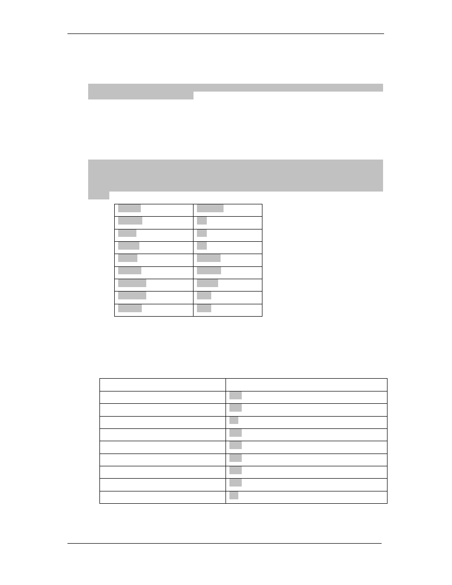
4 Call routing
Clearly state on what field / parameter / information their solution / product can make routing
decisions. The following table lists a number of these fields / parameters / information basis.
Basis of routing decision
Supported by solution
Time of day
Yes
Day of week
Yes
Date of month
No
Special dates / holidays
Yes
Bearer capability / TMR
Yes
DDI number
Yes
A number / CLI
Yes
Based upon inbound route
Yes
Protocol used to present call
No
State if the solution is able to make all routing decisions that it can support on all protocols that it
supports.

IPN
X
M
EDIA
G
ATEWAY
D
EC
04
Version 1.0
December 2004 Page 12 of 28
©
W
ORLD TELECOM
L
ABS
The routing decisions are not affected by the protocol used to receive the traffic.
5 Protocol support
5.1 Protocols supported other than C7 / SS7 and VoIP protocols
List which non C7 / SS7 TDM protocols their solutions supports. Examples of such protocols
includes Euro ISDN, DPNSS, 1TR6.
Other protocols supported are: Euro ISDN (many country variants), CAS (many MFC/R2
variants)
5.2 Inter-working of TDM to TDM protocols
Describe which supported TDM signalling protocols can inter-work with each other. For example
can Euro ISDN signalling inter-work with DPNSS? Can C7 ETSI ISUP Version 1 inter-work with
UK ISUP?
All supported TDM protocols can fully inter-work with each other.
5.3 Inter-working of VoIP to VoIP protocols
Describe which supported TDM signalling protocols can inter-work with each other. For example
can SIP inter-work with H.323 version 2?
All supported VoIP protocols can fully inter-work with each other. SIP signalling inter-works with
H323.
5.4 Inter-working of TDM to VoIP / VoIP to TDM protocols
State which of the supported TDM signalling protocols can inter-work with which supported
VoIP signalling protocols and vice versa.
All supported VoIP and TDM protocols can fully inter-work with each other. This is one of the
design principles of the IPNx switch.
5.5 Inter-working with other vendors
a)
State and describe any interoperability testing between other vendors.
Very little formal interoperability testing has been done with other vendors. However, WTL have
yet to encounter another vendor in our extensive installed base with whom we have been unable
to interconnect.
6 Supplementary services
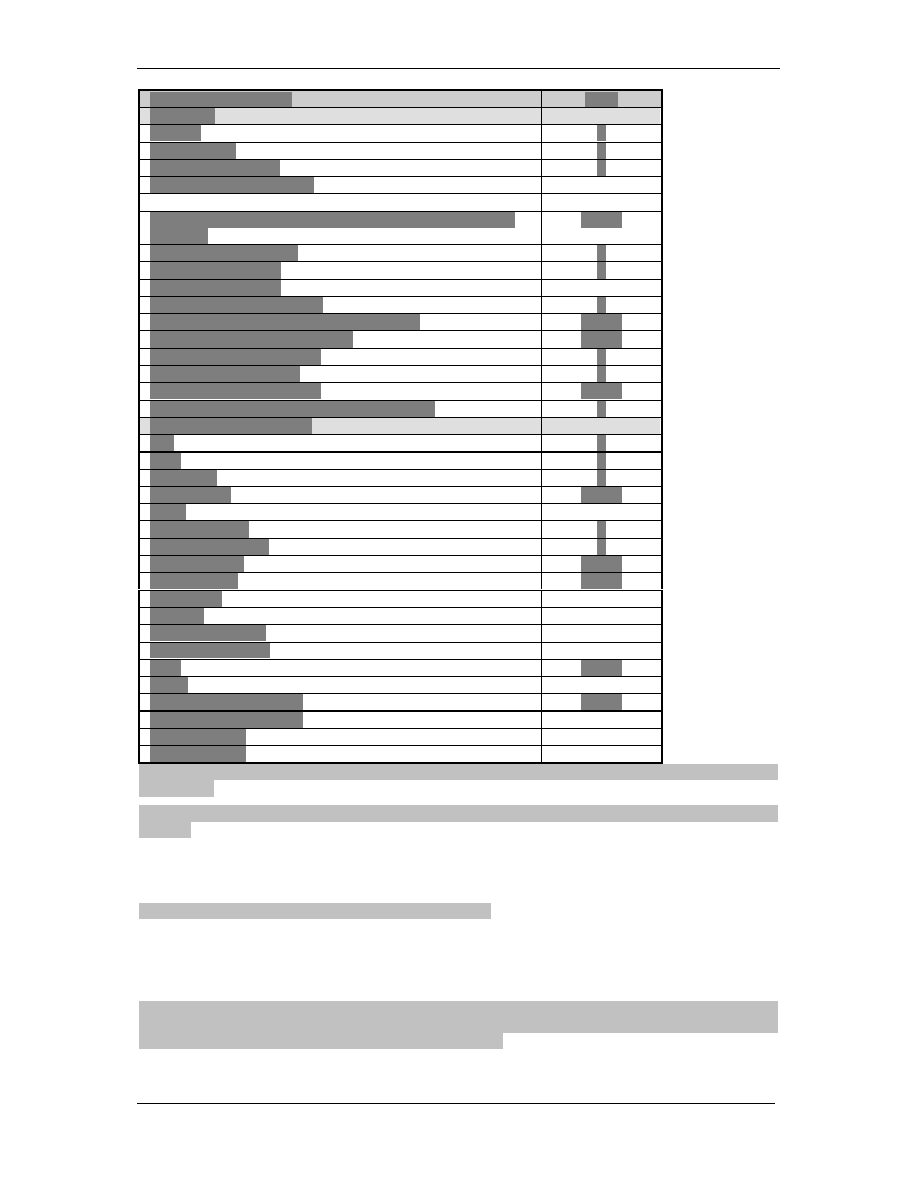
6.1 TDM supplementary services supported
State which supplementary services each implementation of a TDM protocol supports.
IPN
X
M
EDIA
G
ATEWAY
D
EC
04
Version 1.0
December 2004 Page 13 of 28
©
W
ORLD TELECOM
L
ABS
SS7 Function/service
IPNX
Basic call
Speech/
Y
3.1 kHz audio
Y
64 kbit/s unrestricted
Y
Multirate connection types
Signalling procedures for connection type allowing fallback
capability
Note 1
Compatibility procedure
Y
Confusion procedure
Y
Simple segmentation
User part availability control
Y
Propagation delay determination procedure
Note 1
Dynamic echo control procedure
Note 1
Tones and announcements
Y
MTP pause and resume
Y
Access delivery information
Note 1
Transportation of User teleservice information
Y
Supplementary services
DDI
Y
MSN
Y
CLIP/CLIR
Y
COLP/COLR
Note 1
MCID
Sub-addressing
Y
Terminal portability
Y
Call forwarding
Note 1
Call deflection
Note 1
Call waiting
Call hold
Conference calling
Three party service
CUG
Note 1
MLPP
UUS, Service 1 (implicit)
Note 1
UUS, Service 1 (explicit)
UUS, Service 2
UUS, Service 3
Note 1: Although the IPNX does not implement these services, it passes transparently the associated
parameters.
ISDN Services: basic call procedures are all supported plus Charging Pulse and Date & Time on
Connect.
6.2 VoIP supplementary services supported
State which supplementary services each implementation of a VoIP protocol supports.
All H323 basic procedures including RAS are supported.
6.3 Inter-working of supplementary services on TDM to TDM protocols
State which supplementary services can be inter-worked between different TDM protocols. For
example can CLI be inter-worked between ETSI ISUP version 2 and Euro ISDN.
Supplementary services are passed transparently by the IPNx allowing full inter-working. For ISDN
this includes CLI, Subaddressing, Bearer Capability, all contents of the ATP (including Display
Information and Progress Indication) the UTI and the HLC.

IPN
X
M
EDIA
G
ATEWAY
D
EC
04
Version 1.0
December 2004 Page 14 of 28
©
W
ORLD TELECOM
L
ABS
6.4 Inter-working of supplementary services on VoIP to VoIP protocols
State which supplementary services can be inter-worked between different VoIP protocols. For
example can CLI be inter-worked between SIP and H.323.
Supplementary services are passed transparently by the IPNx allowing full inter-working. For
VoIP this includes CLI, Subaddressing, Bearer Capability, all contents of the ATP (including
Display Information and Progress Indication) and the UTI but not the HLC.
6.5 Inter-working of supplementary services on TDM to VoIP / VoIP to TDM
protocols
State which supplementary services on which TDM signalling protocols can inter-work with
which supplementary services on which supported VoIP signalling protocols and vice versa.
Supplementary services are passed transparently by the IPNx allowing full inter-working. For
VoIP to TDM and vice versa this includes CLI, Subaddressing, Bearer Capability, all contents of
the ATP (including Display Information and Progress Indication) and the UTI but not the HLC.
6.6 Inter-working with other vendors
a) State and describe any interoperability testing with other vendors.
Very little formal interoperability testing has been done with other vendors. However, WTL have
yet to encounter another vendor in our extensive installed base with whom we have been unable
to interconnect.
7 Features and services
7.1 IP voice VPN
Describe any IP voice VPN solution provided along with a list and description of the features
provided by the solution. Include the following in the description:
a) VoIP protocols supported.
b) Can the IP voice VPN solution be used for single users i.e. home workers.
c) Can the IP voice VPN solution be used to serve users on a traditional PABX who
access the VoIP network and IP voice VPN solution via a CPE VoIP gateway.
d) What is the maximum number of customers that can be served by the proposed IP
voice VPN solution.
e) What is the maximum number of users that can be served by the proposed IP voice
VPN solution.
Also describe any additional hardware, software and licences that would be required to operate
the IP voice VPN service.
IP voice VPN services supported. Detail to follow.
7.2 TDM voice VPN
Describe any TDM voice VPN solution provided along with a list and description of the features
provided by the solution. Examples of a TDM voice VPN include:
a) Customers from different sites are connected to E1 ports on the softswitch platform and
TDM signalling protocols are used to communicate.
b) IDA customers can use short codes after the IDA code to create a virtual VPN.
Include the following in the description:
a) TDM protocols supported.
b) What is the maximum number of customers that can be served by the proposed TDM
voice VPN solution.
c) What is the maximum number of users that can be served by the proposed TDM voice
VPN solution.

IPN
X
M
EDIA
G
ATEWAY
D
EC
04
Version 1.0
December 2004 Page 15 of 28
©
W
ORLD TELECOM
L
ABS
TDM VPN services not supported
7.3 Number translation services
Describe any solution offered to enable number translation services such as freephone and
premium rate numbers.
Number translation services are supported by the IPNx and are in use by many customers.
Flexible number matching is used to translate the called number. This is tied to a highly
flexible rating system to allow freephone or Premium Rate services. For Premium Rate
services the auto announcement of the cost of the call is supported. This is required by most
countries’ telecom regulations.
7.4 Local Number portability
Describe the solution provided to allow all UK and European regulatory requirements with
regards to local number portability to be met. This description should include any additional
hardware and software requirements.
Local Number portability not supported
7.5 Number portability
Describe any solution provided to allow the portability of non-local numbers. Examples include
freephone and premium rate numbers.
Number portability not supported
7.6 Emergency services
Describe how access to emergency services are provided from the IP / VoIP network to the
PSTN side.
Emergency services not supported
7.7 Legal intercept
Describe the solution provided to allow all UK and European regulatory requirements with
regards to legal intercept to be met. This description should include any additional hardware
and software requirements.
Legal intercept services not supported
7.8 Voicemail / Unified messaging
Describe any solution provided which provides voicemail and unified messaging services.
Voicemail services not supported
7.9 Network ACD
Describe any solution provided which allows a network based ACD service to be offered to
customers. This description should provide information on statistics packages as well as the
call routing functionality of an ACD system.
The IPNx implements a full automatic call distribution for customers who want to offer their
audiotext or operator services via a single number.
Sophisticated options decide where incoming calls are routed for answering:
•
Time of day – up to 7 time periods per day
•
Day of week - 7 different types of day may be defined
•
Capacity of destination
•
CLI of caller
•
DDI that call came in on
•
Number of calls already in the queue waiting to be answered
Careful control over call queues is possible even if queues are spread over multiple IPNxs and
even if they are in physically different locations. Because the algorithm runs on a central host
there is a guarantee of global control on queuing and fallback. This allows all call answering

IPN
X
M
EDIA
G
ATEWAY
D
EC
04
Version 1.0
December 2004 Page 16 of 28
©
W
ORLD TELECOM
L
ABS
resources to be used to their optimum. Call distribution is handled fairly so incoming calls are
presented to each operator in turn (not always to the first in the list).
If a valid destination is not available the call may be held whilst playing music or a suitable
voice message until an operator is available. There is also the capability to tailor these
messages to the waiting caller. For example, “You are currently 3
rd
in the queue”. This is also
an opportunity to play customised advertising messages to the caller.
Finally, if all the queues are full the call is routed to a final recorded message service which
would normally ask the caller to try again later.
7.10 Contact centre solutions
Describe any solution provided which allows a network based contact centre service to be
offered to customers.
Contact centre solutions not supported
7.11 IVR
Describe any IVR solution provided and how it integrates into other applications.
The IPNx offers extensive, integrated IVR support. This is mainly aimed at offering Pre-Paid
and Call Back services to subscribers. The IVR system may support multiple languages and
allows IPNx owners to record their own prompts.
7.12 Voice conferencing
Describe any voice conferencing solution provided.
Voice conferencing services not supported
7.13 Video conferencing
Describe any video conferencing solution provided. Examples include H.323 to H.320
gateways, H.323 gatekeepers, etc.
Video conferencing services not supported
7.14 Multipoint Control Unit (MCU) / Bridging
Describe any MCU / Bridging products / solutions provided. This description should clearly
state if the product / solution can be used for voice, video or both.
MCU services not supported
7.15 Outbound calling
Describe any solution provided which allows the use of a network based outbound calling
service. Include within any description information as to the applications use for home
workers, small offices and larger offices. All of which may operate as a single team working
from the same outbound dialling database.
The IPNx has an interface which allows third party call control (WebConnect). This has been
used to create automated calling systems. WTL can assist the customer in the design of a PC
program which passes information to the IPNx to allow it to make programmed calls and to
monitor the results.
7.16 Text to speech / Speech to text
Provide information on any applications, features and services which provide a text to speech
and / or speech to text functionality.
TTS services not supported

IPN
X
M
EDIA
G
ATEWAY
D
EC
04
Version 1.0
December 2004 Page 17 of 28
©
W
ORLD TELECOM
L
ABS
7.17 Voice XML
State if the solution supports Voice XML and if so which version(s) they support. Describe what
functionality and control Voice XML scripts can have over the various components of the
solution.
Voice XML services not supported
7.18 API’s & programming interfaces
State and describe what, if any, API’s and programming interfaces the solution supports.
Describe what functionality and control such API’s and programming interfaces can have over
the various components of the solution.
The IPNx has a number of APIs which allow the switch owner different levels of control over the
switch:
Web Connect – allows external call control of the IPNx. Typical uses include pre-programmed
outbound calls, Click to Talk buttons on web sites, on-line purchase of telephone services
Wt Agent – allows manipulation of the IPNx database by external processes. Typical uses
include the reading and setting of customer account balances (especially in Pre-Paid
environments).
CDR FTP - daily files exist of the very comprehensive Call Detail Records of the IPNx switch.
External processes may collect these files. For example, a PC utility is also available which
downloads these records reliably into a SQL database for further processing.
Log files – a series of detailed log files may be produced about most aspects of the switch
operation. These are available for downloading into external processes.
Cslog – a streaming socket for real time applications which need immediate call information.
Typical use of this is a real time billing process.
7.19 Other applications and services
Provide information on other related applications, features and services offered.
The additional features offered by the IPNx are mainly in the areas of call rating, Pre-Paid
services and VoIP compression.
8 System architecture
8.1 System architecture
Describe the system architecture of the proposed offering(s). This description should clearly
show the following:
a) How CPE gateways are directed to the softswitch. I.e. static routing, gatekeepers, proxy
servers, TRIP, etc.
b) Redundancy of components and nodes
c) System nodes and how the communicate with each other.
d) The purpose of each system node.
The IPNx is an industrial computer integrated offering all the features required of a small to
medium telecom switch in a single box. The modular architecture allows various interface or
resource cards to be plugged in as the application requires. The switch operating software has
been designed to run each chassis as a self-contained switch regardless of the mix of traffic it is
handling. In addition any number of IPNx switches may be connected in a network. They will
operate in a distributed fashion (each handles its own routing for example although routing
information is shared between the switches).
IPNx Physical Specification Version 2.0
Westek - 8 Slot 9U Chassis
Dual Hot Swap 300W AC Power Supply
Sun Sparc Processor Card with

IPN
X
M
EDIA
G
ATEWAY
D
EC
04
Version 1.0
December 2004 Page 18 of 28
©
W
ORLD TELECOM
L
ABS
440MHz
16 KB Cache
256 MB Memory
4 MB Flash
10/100M Ethernet
2 x 40 GB Hard Disks
Ultra Wide SCSI RAID1 Subsystem
i.
Chassis Specification.
o
Rugged, rack-mountable system chassis with:.
o
8-slot CompactPCI backplane (supports PICMG CompactPCI Full Hot
Swap standard).
o
Hot swap fans (dual fan trays optional).
o
EMC-tight front door.
o
IEEE 1001.11 rear transmission board support.
o
Physical characteristics.
o
Dimensions:.
i.
9U 19" rack-mount standard.
ii.
17" W x 18.5" D x 15.75" H.
iii.
435 mm x 470 mm x 400 mm.
o
Weight:.
i.
78 lbs..
ii.
35.4 kg.
ii.
System Power.
o
Hot Swap dual/quad (n+1) AC or DC power supplies 300 W with dual fan and
power connector per pair
o
Maximum inrush current: 30A
o
Maximum consumption (230V): 7.5A
iii.
Environmental
o
Operating Range:.
o
Temperature: 5
º
C to 40
º
C.
o
Relative Humidity: 20% to 80% at +20°C to +40°C, non-condensing.
iv.
Agency Approvals.
o
CE Declaration of Conformity (EN 50081-1, EN 50082-1, EN 60950).
o
FCC Part 15 Class A.
o
VCCI Class A.
o
UL 1950.
MTBF Figure for the CP1500 Processor Card 151,479 Hours
Communications Cards
ISDN, E1, SS7 - Brooktrout PRI-CPCI NS301
VoIP - Audiocodes TP1610 (120 - 480 channels)
Inter-chassis - Kallastra KeyTrunk313 (1024 channels) or Keytrunk315 (2048 channels)
8.2 Operating system
State which operating system(s) is used for each component within the system architecture.
This also applies to platforms running any of the proposed applications.
The IPNx operating system is Solaris 7
9 Quality of service
Describe what IP quality of service (QOS) mechanisms the products provide. This description should
explain if it is possible to have separate QOS settings for the VoIP signalling and the media streams.
The IPNx can use the ToS bit to prioritise voice traffic in a mixed voice and data network. Also the
IPNx always uses the same IP ports to transmit VoIP. This allows these ports to be prioritised by
routers over other traffic on other ports.

IPN
X
M
EDIA
G
ATEWAY
D
EC
04
Version 1.0
December 2004 Page 19 of 28
©
W
ORLD TELECOM
L
ABS
10 Security
10.1 Call verification and authorisation
Describe how outgoing VoIP calls from the IP network to the PSTN are verified and authorised.
Outgoing VoIP calls may be authorised in a number of ways:
Caller’s Ip address
DDI called
CLI of the user
A PIN number may be checked (this may be explicitly requested or may be built into the user’s
call request).
10.2 Encryption of the VoIP signalling messages
Clearly state what if any encryption of the VoIP signalling is possible.
VoIP signalling messages are not encrypted.
10.3 Encryption of the VoIP media stream
Clearly state what if any encryption of the VoIP media stream is possible.
VoIP media stream are not encrypted.
10.4 Unauthorised access
Clearly describe how unauthorised access to the various components and nodes of the solution
(C7 / SS7, IP Centrex and any applications) is provided.
The IPNx has a management and configuration interface which uses ssh for log in and is
password protected.
11 Scalability
11.1 Call processing scalability for softswitch
Provide information regarding the performance of the core softswitch solution (excluding
applications). This information should include but is not necessarily limited to:
a) Maximum calls per second / BHCA
b) Maximum number of sustained calls.
c) Storage capacity of any databases related to the core solution
d) Maximum number of users per node.
e) Maximum number of E1’s per media gateway (M.G.).
f) Maximum number of VoIP calls per media gateway.
g) Maximum number of media gateways per media gateway controller (MGC).
Any other information concerning core softswitch solution scalability should be provided.
a) BHCA 300,000
b) Max calls 3360
c) Storage: no relevant limit
d) Max users: same as max number of calls
e) Max E1s: 112 for single redundant system expandable to 2048 E1s for multiple linked
redundant systems
f) Max VoIP calls: 960
g) System is not based on MG and MGC. Maximum of linked systems is 64.

IPN
X
M
EDIA
G
ATEWAY
D
EC
04
Version 1.0
December 2004 Page 20 of 28
©
W
ORLD TELECOM
L
ABS
11.2 Applications scalability
For each application, feature or service provided information concerning its scalability
should be provided. This information should include (where applicable) but is not
necessarily limited to the following:
h) Maximum calls per second / BHCA
i) Maximum number of sustained calls.
j) Storage capacity
k) Maximum number of users.
l) Maximum number of groups (for applications such as ACD, etc)
m) Maximum number of users per group
Any other information concerning application scalability should be provided.
h) Maximum calls per second / BHCA : 300,000
i) Max calls 3360
j) Storage: 4Gb
k) Max users: same as max number of calls
l) Max groups:128
m) Users per group: no limit
12 Reliability
Clearly describe the reliability of the products, applications, features and services described. This
description should include (but is not necessarily limited to):
a) Average down time per year.
The only single point of failure for the IPNx is the CPU card (although this may be avoided in the
redundant configuration outlined here). The MTBF for the CPU card is 151,479 Hours.
13 Approvals
a) Provide a list of all approvals gained for any of the products, applications, features or services
that described.
The IPNx and the communication cards that make it up have the relevant telecom and safety
approvals. This includes:
o
CE Declaration of Conformity (EN 50081-1, EN 50082-1, EN 60950).
o
FCC Part 15 Class A.
o
VCCI Class A.
o
UL 1950.
14 Billing
14.1 Customer billing
Describe how billing for CPE customers is accomplished.
Also provide a description of the possible CDR fields that can be output and also explain if
it is possible to configure what fields are output within CDR’s.

IPN
X
M
EDIA
G
ATEWAY
D
EC
04
Version 1.0
December 2004 Page 21 of 28
©
W
ORLD TELECOM
L
ABS
The IPNx generates a CDR for every call wherever it is originated (on VoIP, via TDM or SS7).
Each CDR contains 47 fields. It is not possible to configure the CDR contents. The fields are
defined below.
The CDRs are located in two directories on the switch depending upon the service:
•
Non-calling card
service CDRs are located in /usr2/CDR directory
•
CDRs for
calling cards
are located in /usr2/DEBIT directory
CDRs are accumulated in a daily file with the name YYYYMMDD where YYYY is the year, MM
the month and DD the day.
CDRs are retained on the switch for 31 days.
The CDRs are also exported (at a configurable interval) to a management PC for off-line
processing. This processing may be done by the WTL Billing application or a 3
rd
party billing
package. To allow the latter case a scriptable utility is available which can reformat some or all
of the CDR into the style required by the external Billing package.
There is no limit to the length of time CDRs may be retained in the Billing database.
The CDR format is:
Field
Name
Description
# of chars, type,
fixed? [note]
1
CID
Company ID or provider ID if pre-paid
service
8, A, Y
2
Unixtime
Time in seconds since 1970 (Unix time)
9, N, N
3
Duration
Duration of call in seconds; 0 if no connect
4, N, N
4
Switchunit
Switch # on which call originated: 5 digits,
first 4 = node #, last digit = sw #
5, A, Y
5
Time
Time connect was started or time of
disconnect if not connected
8, T, Y
6
Date
Date in DD.MM.YY (US format) or
DD.MM.YYYY
10, D, Y
7
Jobnumber
Job number (for billing purposes. It is also
an extra level of security - password -
provided by the switch.)
19, A, N
8
PIN or CLI
CLI or PIN code (depending upon service)
25, A, N
9
B-Number
Destination number (international format)
24, A, N [max 12
numeric, never
alpha]
10
Outbound
line
Out bound Line # (1 - N) per switch
3, N, N
11
Outbound
carrier
Outbound carrier # on which call was
placed
1, A, Y
12
Initial rate
Call rate in cents/minute (cents = 1/100 of
currency unit)
5, N, N
13
Cost
Call cost in cents (cents = 1/100 of currency
unit)
5, N, N
14
DNIS
Dialed Number Identification Source = City
code + DDI (Direct Dial in Number) on
which call was received
24, A, N
15
Operator
number
Telephone number of operator for operator
assisted calls. It contains the telephone
number of the operator position for
operator-assisted calls (debit service only).
Although this field is currently unused for
business service, it will be present as an
empty field in the extended CDR of
business calls.
20, A, N
16
Balance left
Balance in cents remaining on the account
after the call
9, N, N
17
Inbound (A-
Leg) carrier
For SCX calls (not reported in CDR file), this
will be 0
4, N, N
18
Inbound line
According to PORT table
3, A, Y

IPN
X
M
EDIA
G
ATEWAY
D
EC
04
Version 1.0
December 2004 Page 22 of 28
©
W
ORLD TELECOM
L
ABS
19
Cause value
Disconnection cause value in INX format
(ISDN cause=1512+ISDN cause), 0 if none
5, N, N
20
Transmit
Medium
Requirement
(TMR)
This numeric parameter represents the type
of call. It can take the following values:
0: the call is a speech only call (no fax or
modem signals)
2: the call is a 64Kb/s unrestricted digital
call
3: the call is an audio call. The audio signal
can be speech, fax or modem and any other
inband (0-3KHz) signal
6: the call is a 64Kb/s unrestricted
"preferred" call. This is treated by the INX
as a TMR 2 but with the possibility for a
subsequent switch to fallback to an audio
call quality. The CDR does not reflect
whether the fallback has occurred or not.
1, N, Y
21
Duration of
the A-leg
connection
This field will be set for call-through and
callback and represents the total connected
time since beginning of call. If there are
several CDRs recorded during the call (LCR
attempts or joint call feature), they will all
have this field set with increasing values.
The duration is counted from the time the A-
leg is connected, it does not include ringing
time for direct or carrier select services
where the inbound call is not connected
before the B-leg leg is connected
8, N, N
22
Telephone
number in
international
format of A-
leg leg when
there is a
callback
This field will only be set on the last CDR
when the A-leg is disconnected and only if
the A-leg is a callback call. It is intended to
facilitate the collection of callback calls for
accounting. Note that if the callback call
fails, it is reported as a normal outbound call
failure (the callback number is in the
destination number field).
24, A, N
23
Number of
busy lines on
the A-leg
carrier (field
17) at the
time of the
CDR time
stamp (field 5
and 6)
This is the total number of busy lines
(inbound or outbound calls, connected or
progressing calls) on all lines to the carrier
on the switch. In case of callback, the A-leg
carrier is the carrier on which the callback
call has been successfully placed.
4, N, N
24
Number of
busy lines on
the B-leg
carrier at the
time of the
time stamp
This is the total number of busy lines
(inbound or outbound calls, connected or
progressing calls) on all lines to the carrier
on the switch.
4, N, N
25
Total
outbound call
time in
seconds
This is the time between the initial dialing
and the disconnection of the B-leg. The
duration of the dialing and ringing stage can
be deduced by subtracting the B-leg
connection time (field 3). The duration of the
dialing stage alone cannot be deduced.
8, N, N
26
Disconnectio
n origin
0 = the disconnection is initiated internally
(timeout, balance expiry, ...)
1 = the disconnection is coming from the A-
1, N, Y

IPN
X
M
EDIA
G
ATEWAY
D
EC
04
Version 1.0
December 2004 Page 23 of 28
©
W
ORLD TELECOM
L
ABS
leg
2 = the disconnection is coming from the B-
leg
27
Type of PIN
Specifies content of CDR field 8 First letter:
D
debit number from DEBIT.DEBIT_NR
(can be a ordinary debit number or a
debit CLI (starts with letter 'O'))
P
pin code from PIN.PIN
O
CLI from PIN.PIN
R
redirecting number from PIN.PIN
H
H323 pin code from PIN.PIN
I
IP address from PIN.PIN formated as
xxx.xxx.xxx.xxx
C
CSTA from PIN.PIN formated as
SSSSSCCC where SSSSS is the switch name
in 5 characters and CCC is the inbound line
CSTA in 3 characters.
Second letter:
N
if the PIN or DEBIT number has been
created by the switch
The field is appended with N if field 8 contains a
newly created PIN or DEBIT record. This is
used in services where the switch can generate
PIN or DEBIT record by itself (REGISTER,
RECHARGE)
If field 8 is empty, field 27 will also be empty
2, A, N
28
CLI
CLI of the call obtained from different sources:
for C,O,D inbound carriers, replaced A
number from PIN.CLI according to PIN.CLIUSE.
for callback service with PIN.CLIUSE=B
or b, replaced A-number from PIN.CLI
for tdial test calls, from –a option
otherwise unconverted A-number from
inbound call
16, A, N
29
B-Leg node
number
When the B-leg carrier is a VoIP carrier, this
field contains the node number to which the call
has been sent. Empty otherwise.
5, A, N
30
PIN service
code
When the call is authenticated by a PIN record,
this field contains the PIN.SERVICE field:
O for CLI based authentication on O,P carriers
C for CLI based authentication on C carrier
1, A, Y

IPN
X
M
EDIA
G
ATEWAY
D
EC
04
Version 1.0
December 2004 Page 24 of 28
©
W
ORLD TELECOM
L
ABS
D for CSTA based authentication on D carrier
H for PIN based authentication on DDI service
H,U or on H carrier
S for CLI based authentication on DDI service
S
I for CLI and DNIS based authentication on
DDI service I
B for DNIS based authentication on DDI
service B
If the call is not authenticated by a PIN
record, this field is empty
31
A-leg rate
Initial A-leg rate or 0 if the A-leg is not charged.
The A-leg rate does not change during the call.
6, N, N
32
A-leg cost
Total cost of A-leg or 0 if the A-leg is not
charged.
9, N, N
33
Type of CDR Indicates the position of the CDR in the call.
0
intermediate CDR, A-leg still in progress,
B-leg disconnected
1
terminating CDR, A-leg and B-leg
disconnected
2
intermediate CDR, callback A-leg
disconnected
3
intermediate CDR, no A-leg or B-leg
change, just updated balance
4
tdial test CDR
5
webconnect terminating CDR leg 1
6
webconnect terminating CDR leg 2
7
transit intermediate CDR (carrier V,W,X)
8
transit terminating CDR (carrier S,V,W,X)
9
TNS calls
Note: when debit cards are used to recharge an
account, a CDR will be created in debit
CDR file with the balance of the recharging
cards, There will be no A-leg and B-leg,
just an updated balance. The type of CDR
will be 3 with no A-leg and B-leg number,
cost or rate. The company ID (field 1) will
be set from the card being recharged (the
active card), not the recharging card.
2, N, N
34
Type of
balance
Indicates the type of balance in field 16 2, N, N

IPN
X
M
EDIA
G
ATEWAY
D
EC
04
Version 1.0
December 2004 Page 25 of 28
©
W
ORLD TELECOM
L
ABS
0
no balance is charged
1
debit balance is charged
2
pin balance is charged
3
company balance is charged
35
B-leg format
Indicates if the B-leg number in field 9 is in
international format or not
B-leg number is unformated
B-leg number is formated (processed by
inrule1 table) and should be in international
format.
2, N, N
36
B-leg number
heading
Content of ROUTE1.AREACODE field
(ROUTE.AREACODE if slice routing is used)
which has been used to route the B-leg. Empty
if there was not B-leg or if the
ROUTE1.AREACODE (ROUTE.AREACODE)
field was empty.
This is useful for statistical purposes to sort the
calls by selected destinations without having to
run pre-processing routines on the CDR.
Note that the route table should have a
meaningful list of destinations for this field
to contain useful information, even if the
routing is simple: all redundant route
records can point to the same carriers.
16, A, N
37
B-leg post
dial delay
Time is seconds between the end of dialling
and the start of the ringing phase.
The ringing phase starts when an Alerting (or
equivalent) message is received from the B-
leg. If no Alerting is received, the PDD ends
when the call fails or is connected.
Note that for calls with overlap sending, the
dialling ends when the switch 1) detects a
timeout on the incoming digits 2) detects a
"end-of-dialling" signal from the inbound side 3)
receives a Proceeding/Alerting/Connect
message from the outbound side.
In case 1, the timeout is counted as part of the
PDD, in case 2, the PDD starts with the "end-
–dialling" signal, in case 3, the PDD will be 0 if
an Alerting/Connect message is received.
8, N, N
38
CLI nature of
address
Holds the CLI nature of address parameter
received from the inbound carrier. It defines the
type of number stored in field 28. Possible
values:
1, N, Y

IPN
X
M
EDIA
G
ATEWAY
D
EC
04
Version 1.0
December 2004 Page 26 of 28
©
W
ORLD TELECOM
L
ABS
0
unknown type of number
no CLI is provided
3 national number
4 international number
39
B-leg routing
ID
Content of ROUTE1.ROUTEID field
(ROUTE.ROUTEID if slice routing is used)
which has been used to route the B-leg. Empty
if there was no B-leg or if the
ROUTE1.ROUTEID (ROUTE.ROUTEID) field
is empty.
In case of indirect route (ROUTE_COD
field used), this field holds the initial route
ID, not the ROUTE_COD field.
6, A, N
40
A-leg zone
Content of RATE.C_CODE field used to rate
the A-leg. Empty if the A-leg is not rated or if
RATE.C_CODE field is empty.
16, A, N
41
A-leg rate ID
Content of RATE.RATE_ID field used to
rate the A-leg. Empty if the A-leg is not
rated or if RATE.RATE_ID field is empty In
case of indirect rating (RATE_CLI or
RATE_COD used), this field holds the
iniital rate ID, not the RATE_CLI or
RATE_COD.
6, A, N
42
B-leg zone
Content of RATE.C_CODE field used to rate
the B-leg. Empty if the B-leg is not rated or if
RATE.C_CODE field is empty.
16, A, N
43
B-leg rate ID
Content of RATE.RATE_ID field used to rate
the B-leg. Empty if the B-leg is not rated or if
RATE.RATE_ID field is empty.
In case of indirect rating (RATE_CLI or
RATE_COD used), this field holds the iniital
rate ID, not the RATE_CLI or RATE_COD.
6, A, N
44
Agent ID
Holds the agentid used for the call. Empty if no
agentid was selected.
3,A,N
45
Call ID
Holds the call id assigned to the call by the
switch software. This call id is a small number
(1-9999) assigned cyclically by the switch and
maintained for the entire duration of the Aleg.
The call id is also used in the log file to tag all
log entry of the call. The call id is unique per
INX at a particular point of time but is not
globally unique: two INX can have the same
call id at the same time and the same call id
can be reused every 10 minutes or so on a
busy INX.
This field can be useful for statistical purposes
to link several CDR together: consecutive
CDRs from the same calling card number
having the same calling id field are chained
CDR
4,N,N
46
Batch ID
Holds the batch id of the card copied from
6,A,N

IPN
X
M
EDIA
G
ATEWAY
D
EC
04
Version 1.0
December 2004 Page 27 of 28
©
W
ORLD TELECOM
L
ABS
DEBIT.BATCHID. Only set for debit calls,
empty otherwise.
47
Caller
Category
Holds the caller category as received from the
inbound call data. It matches the SS7 definition
for caller category:
10 : ordinary subscriber
15 : payphone
For non-SS7 incoming calls, the caller
category is set by default to 10 unless a
payphone is detected via the PIN table in which
case the caller category is set to 15. This field
can be used to determine if the call was
coming from a payphone or not.
2,N,N
14.2 Interconnect billing for C7 / SS7
Describe how billing for C7 / SS7 interconnect is accomplished.
Also provide a description of the possible CDR fields that can be output and also explain if
it is possible to configure what fields are output within CDR’s.
The IPNx generates a CDR for every call wherever it is originated (on VoIP, via TDM or SS7).
Each CDR contains 47 fields. It is not possible to configure the CDR contents. The fields are
defined above.
14.3 Interconnect billing for VoIP
Describe how billing for VoIP interconnect is accomplished.
Also provide a description of the possible CDR fields that can be output and also explain if
it is possible to configure what fields are output within CDR’s.
The IPNx generates a CDR for every call wherever it is originated (on VoIP, via TDM or
SS7). Each CDR contains 47 fields. It is not possible to configure the CDR contents. The
fields are defined above.
15 Fraud detection
Any fraud detection abilities / facilities of any component of the core softswitch, IP Centrex and other
applications should be described. This ability may be real time or otherwise. If non-real time the time
delay before possible frauds are announced should be stated.
This description should include any additional hardware and software requirements.
The IPNx has fraud detection mechanisms associated with subscriber authorisation. For example, the
number of bad PIN number attempts allowed can be configured and an alarm raised if this is
exceeded. Account limits may also be set (based on value or calling time).
16 Operations and support
16.1 Management system
Provide information relating to how any proposed products are managed. This information
may relate to management systems, web interfaces or simple command line terminal
sessions.
A number of PC applications are available to assist the management of the IPNx. In
addition all operations may also be carried out using the command line interface of the
switch.

IPN
X
M
EDIA
G
ATEWAY
D
EC
04
Version 1.0
December 2004 Page 28 of 28
©
W
ORLD TELECOM
L
ABS
IPNx Monitor
from World Telecom Labs monitors the health and operation of any number
of our switches.
Graphical display of switches and trunks
Simple colour coding to indicate alarms received
Ability to view recent alarms
Choose which switches to monitor and how frequently
Instant view of total calls, calls & ASR per switch and calls per trunk
Emails sent if certain events occur
Status Display
A tree view is used to show the current status of all switches currently being monitored. The
top level shows the name, IP address and number of current open calls of each switch. A
coloured icon is used for each switch to indicate if there are any outstanding alarms. The
tree view can be expanded to give information on each trunk in a switch. Each trunk can be
named (for example with the carrier’s name) and the current number of open calls is shown.
Again the trunk is colour coded to highlight errors.
Sophisticated Email-based reporting
IPNx Monitor
is also designed for unattended operation. There is a highly configurable
system of email-based reporting.
Configurable limits before emails are sent
Different action rules for day and night (so emails can be sent when engineers off-
duty)
Multiple engineers’ email addresses can be included
Different alarm levels trigger emails to different people (for example, only send major
alarms to manager)
Alarms & Limits
Alarms are generated for a variety of network and switch events. A number of these can be
set to generate alarms at configurable thresholds.
Switch
events
Network events
Other
Processor
activity too high
Level 1 errors
Number of zero length calls per
hour
Disk
capacity
running out
Line timeouts
Bad PINs
Lack of memory
available
Carrier full
Balance exhausted
CDR Directory
getting full
Trunk idle for too
long
Too many users on one account
The most recent alarms are displayed in a scrollable window. These alarms are held by the
switch until they are acknowledged by the user so that alarm messages cannot be lost even
when the PC is turned off.
Wyszukiwarka
Podobne podstrony:
Adresy IP
w8 VLAN oraz IP w sieciach LAN
ADRESACJA W SIECIACJ IP
SNMP (IP)
Adresy IP
ip 11 04
Microsoft PowerPoint IP tryb zgodnosci
CGEIB IP
ZAPROSZENIE, Documents, IP Zielona gora, mat inf
Podsumowanie pracy Zespołu Informacji Publicznej i Współpracy z innymi za rok 2015, Documents, ip, s
ip
Slayers Sorai SS7
IP lab5ad
Protokół TCP IP, R03 5
IP 2
Protokol TCP IP R08 5 id 834124 Nieznany
Bardzo krótko o TCP IP adresacja w sieciach lokalnych
więcej podobnych podstron