
BODY
ELECTRICAL
S Y S T E M
Return To Main Table of Contents
GENERAL . . . . . . . . . . . . . . . . . . . . . . . . . . . . . . . . . . . . . . . . . . . . . .
ELECTRICAL COMPONENT LOCATION . . . . . . . . . . . . . . . . 7
FUSIBLE LINKS AND FUSES . . . . . . . . . . . . . . . . . . . . . . . . .
IGNITION SWITCH . . . . . . . . . . . . . . . . . . . . . . . . . . . . . . . . . . . .
MULTIFUNCTION SWITCH . . . . . . . . . . . . . . . . . . . . . . . . . . . .
INSTRUMENTS AND WARNING SYSTEM . . . . . . . . . . . . 2 2
LIGHTING SYSTEM . . . . . . . . . . . . . . . . . . . . . . . . . . . . . . . . . . . . 3 3
WINDSHIELD WIPER AND WASHER . . . . . . . . . . . . . . . . . . 5 5
ClGARETTE LIGHTER . . . . . . . . . . . . . . . . . . . . . . . . . . . . . . . . .
SUN ROOF . . . . . . . . . . . . . . . . . . . . . . . . . . . . . . . . . . . . . . . . . . . .
TIME AND ALARM CONTROL UNIT . . . . . . . . . . . . . . . . . . 6 8
TAIL GATE OPENER (TRUNK LID OPENER) . . . . . . . . . . 7 3
A/T AND KEY LOCK CONTROL SYSTEM . . . . . . . . . . . . . . . 7 5
GENERAL
GENERAL
SERVICING THE ELECTRICAL SYSTEM
1.
Prior to servicing the electrical system, be sure to turn off
the ignition switch and disconnect the battery ground cable.
NOTE:
On the course of MPI or ELC system diagnosis, when the
battery cable is removed, any diagnostic code retained by
the computer will be cleared.
Therefore, if necessary. read the diagnostic codes before
removing the battery cable.
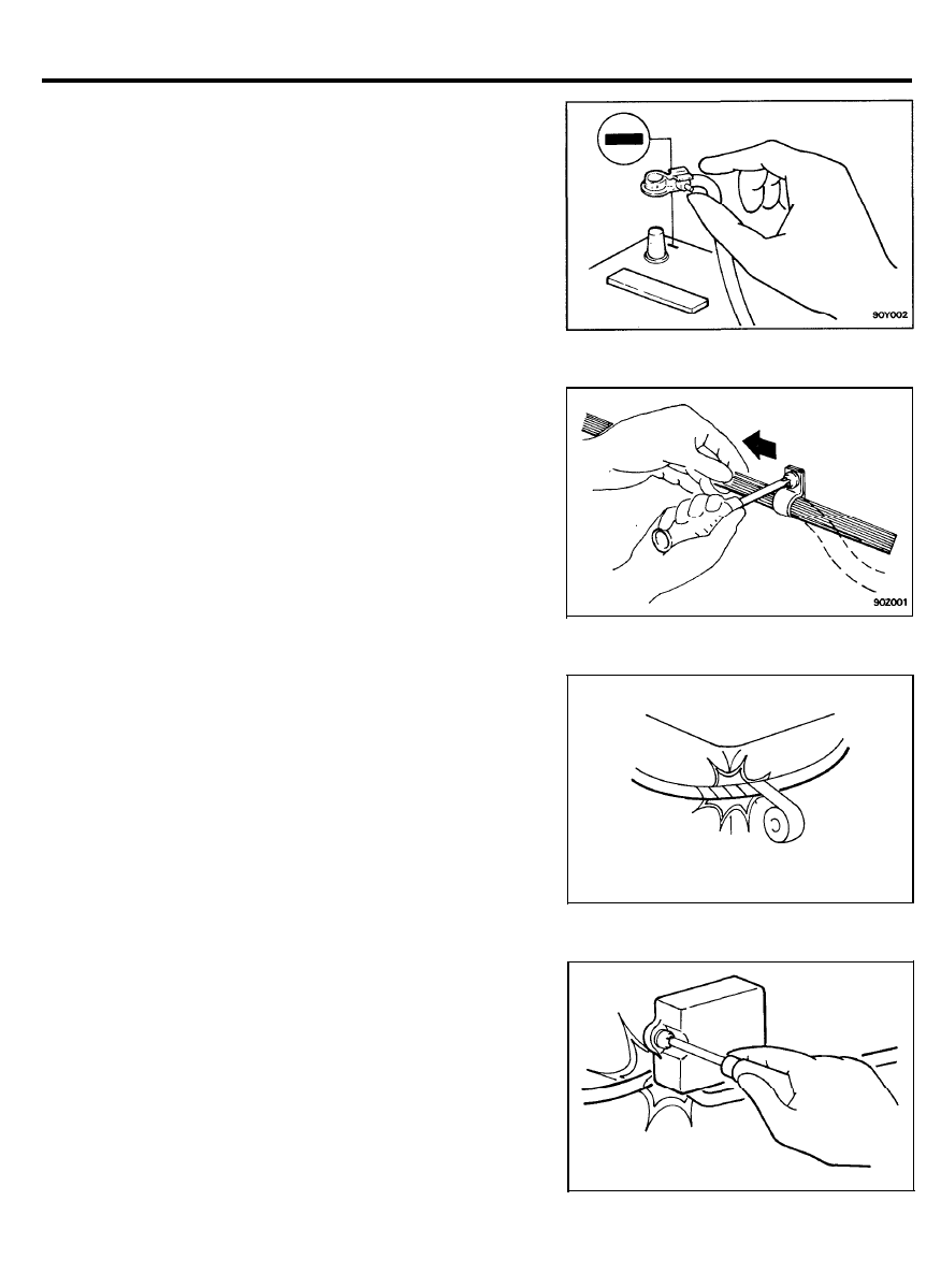
2.
Secure the wiring harnesses by using clamps so that there
is no slack. However, for any harness which passes to the
engine or other vibrating parts of the vehicle, allow some
slack within a range that does not allow the engine
vibrations to cause the harness to come into contact with
any of the surrounding parts, and then secure the harness
by using a clamp.
3.
If any section of a wiring harness interferes with the edge
of a part, or a corner, wrap the section of the harness with
tape or something similar in order to protect it from damage.
4. When installing any of the vehicle parts, be careful not to
pinch or damage any of the wiring harnesses.
9 0 - 2
GENERAL
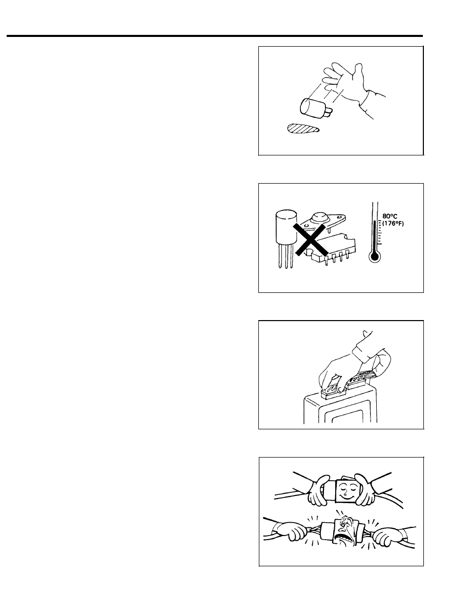
5.
The sensors, relays, etc, must never be subjected to strong
shocks. Do not allow them to fall and do not throw them
when handling.
6. The electronic parts used in the computer, relays, etc. are
readily damaged by heat. If there is a need for service
operations that may cause the temperature to exceed 80°C
(176°F). remove the electronic parts beforehand.
7. Loose connectors could be troubled. Make sure that
connectors are connected securely.
8. When removing a connector, be sure to pull only the
connector, not the harness.
9 0 - 3
GENERAL
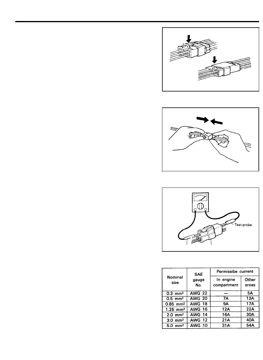
9. Remove connectors which have catches by pressing in the
direction indicated by the arrows in the illustration.
10. Connect connectors which have catches by inserting the
connectors until a “snap” noise is heard.
11. When using a circuit tester to perform continuity or voltage
checks on connector terminals, insert the test probe from the
harness side.
If the connector is a seales connector, insert the test probe
in through the hole in the rubber cap for the electrical wires,
being careful not to damage the insulation of the wires;
continue to insert the test probe until it contacts the
terminal.
12. In order to avoid overloading the wiring, take the electrical
current load of the optional equipment into consideration,
and determine the appropriate wire size.
Test probe
Connector
9 0 - 4
GENERAL
C H E C K I N G C A B L E S A N D W I R E S
1.
2.
3.
4.
5.
6.
7.
8.
9.
Checking the terminal for tightness.
Check terminals and wires for corrosion by battery
electrolyte, etc.
Check terminals and wires for open circuit or impending
open circuit.
Check wire insulation and coating for damage, cracks and
degrading.
Check conductive parts of terminals for contact with other
metallic parts (vehicle body and other parts).
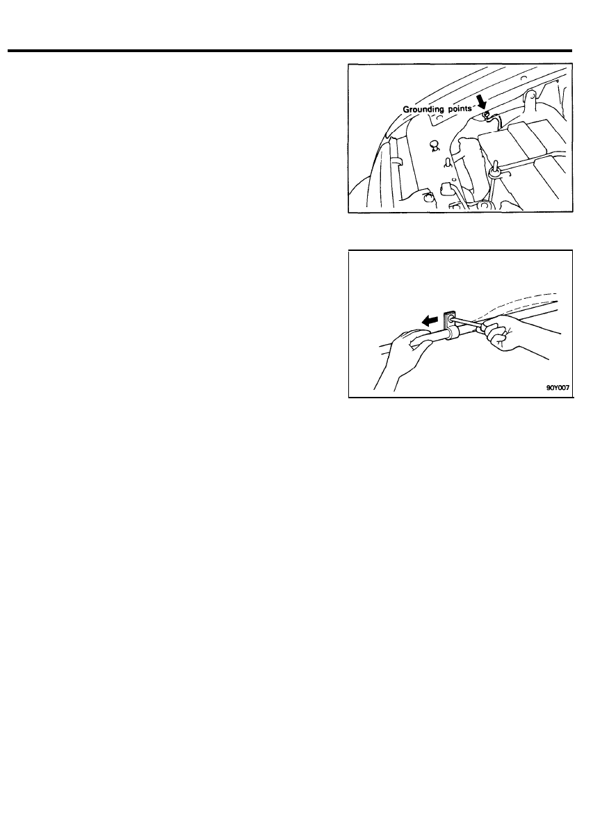
Check grounding parts to verify that there is complete
continuity between attaching bolt(s) and vehicle body.
Check for incorrect wiring.
Check that wirings are so clamped as to prevent contact with
sharp corners of the vehicle body, etc. or hot parts (exhaust
manifold, pipe, etc.).
Check that wirings are clamped firmly to secure enough
clearance from the fan pulley, fan belt and other rotating or
moving parts.
10. Check that the wirings between the fixed parts such as the
vehicle body and the vibrating parts such as the engine are
made with adequate allowance for vibrations.
9 0 - 5
GENERAL
INSTALLATION OF RADIO EQUIPMENT
The computers of the electronic control system has been
designed so that external radio waves will not interfere with their
operation.
However, if antenna or cable of amateur transceiver etc. is
routed near the computers, it may affect the operation of the
computers, even if the output of the transceiver is no more than
25W.
To protect each of the computers from interference by
transmitter (hum, transceiver, etc.) the following should be
observed.
1.
2.
3.
4.
5.
Install the antenna on the roof or rear bumper.
Because radio waves are emitted from the coaxial cable of
the antenna, keep it 200 mm (8 in.) away from the computers
and the wiring harness, route it so that it runs at right angles
to the wiring harness.
The antenna and the cable should be well matched, and the
standing-wave ratio* should be kept low.
A transmitter having a large output should not be installed
in the vehicle.
After installation of transmitter, run the engine at idle, emit
radio waves from the transmitter and make sure that the
engine is not affected.
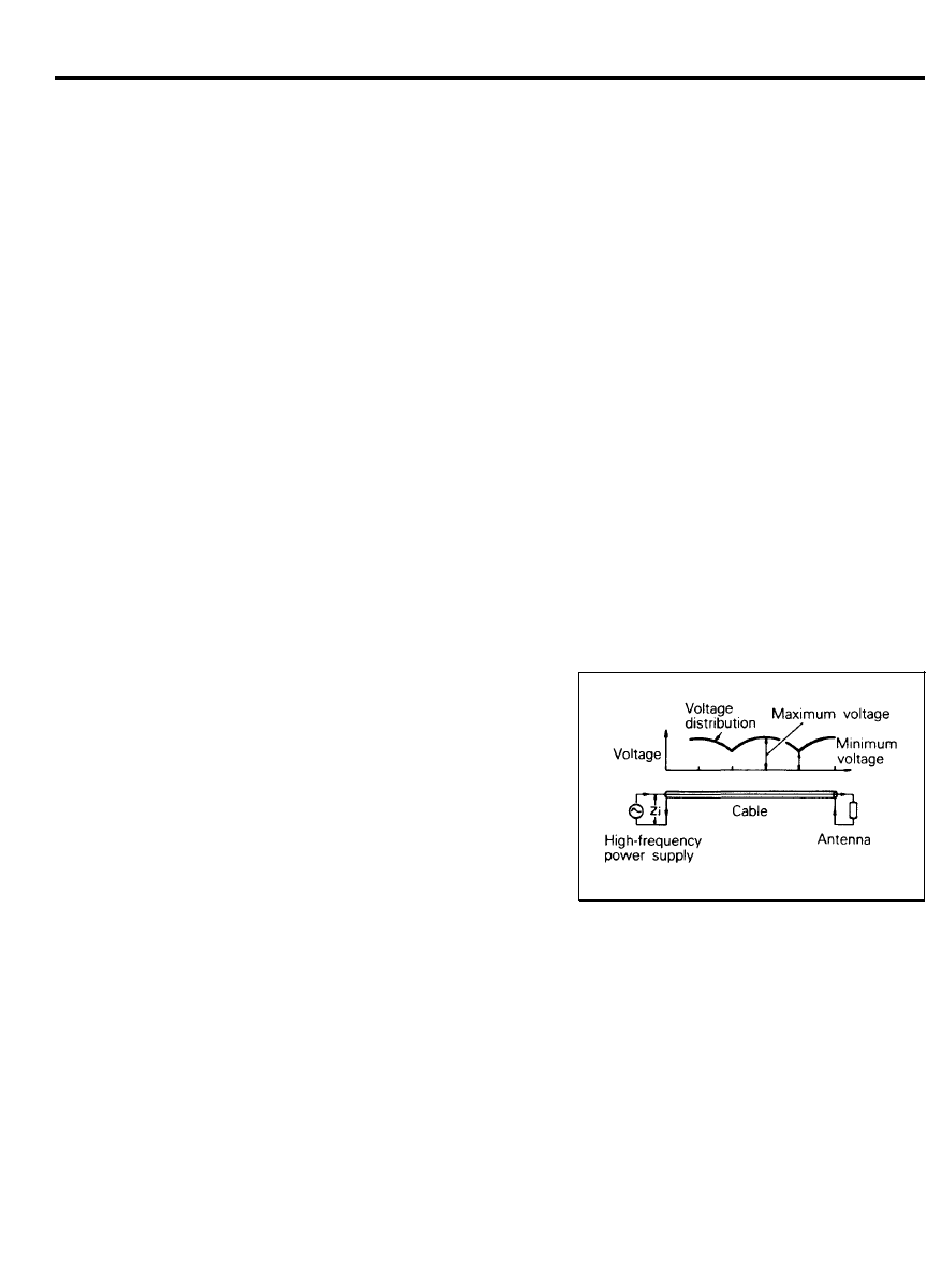
* STANDING-WAVE RATIO
If an antenna and a cable having different impedances and
connected, the input impedance Zi will vary in accordance with
the length of the cable and the frequency of the transmitter, and
the voltage distribution will also vary in accordance with the
location.
The ratio between this maximum voltage and minimum voltage
is called the standing-wave ratio. It can also be represented by
the ratio between the impedances of the antenna and the cable.
The amount of radio waves emitted from the cable increases as
the standing-wave ratio increases, and this increases the
possibility of the electronic components being adversely affected.
9 0 - 6
ELECTRICAL COMPONENT LOCATION
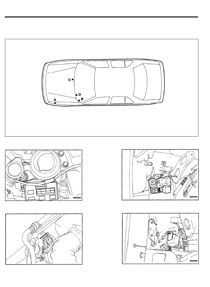
ELECTRICAL COMPONENT LOCATION
RELAY
A. Fender apron outer panel
B. Decker member (cowl cross upper member)
C. Dash panel
D. Cowl cross lower member
A. Relay box (Engine compartment)
8. Relay box (Passenger compartment)
C. Resistor with diode
D. Control relay
9 0 - 7
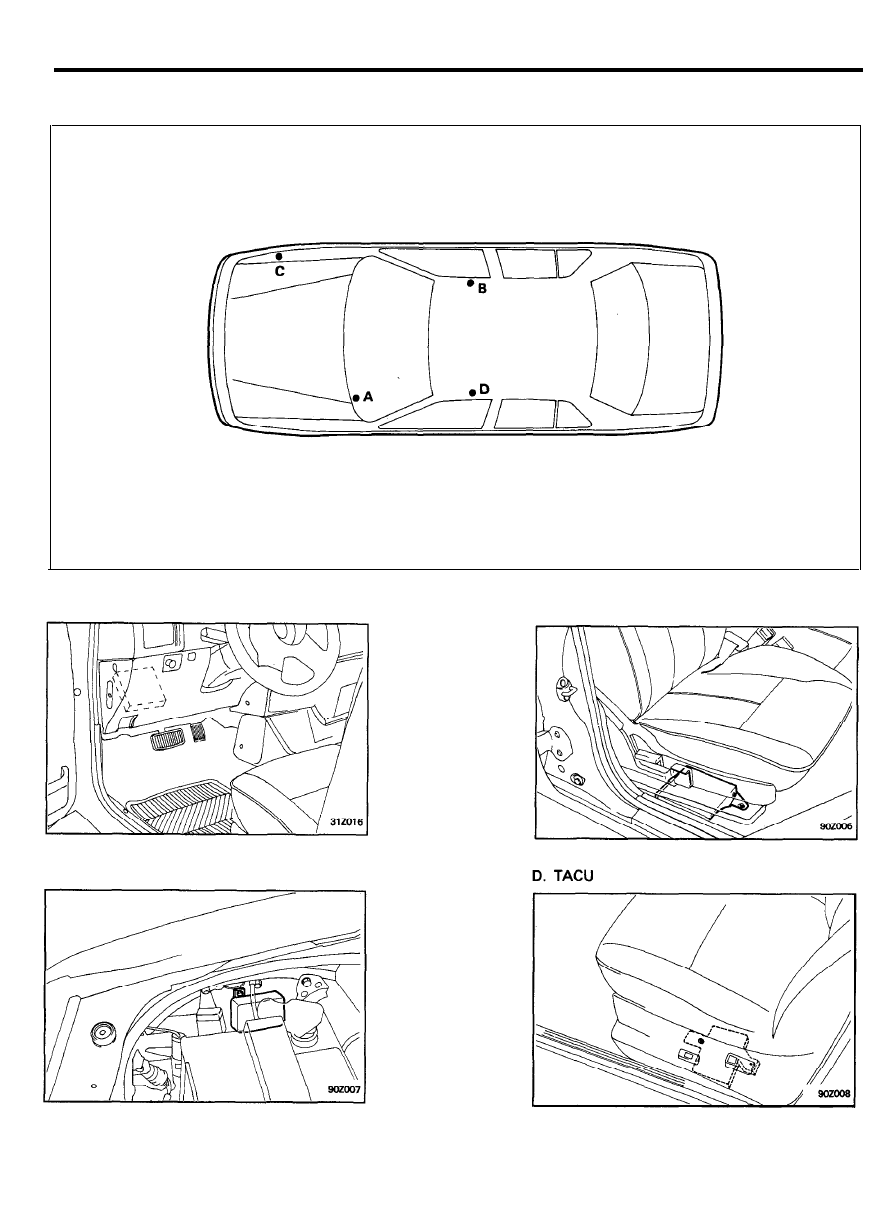
ELECTRICAL COMPONENT LOCATION
C O N T R O L U N I T
A. ECU
C. D.R.L. unit (Canada only)
B. TCU
9 0 - 8
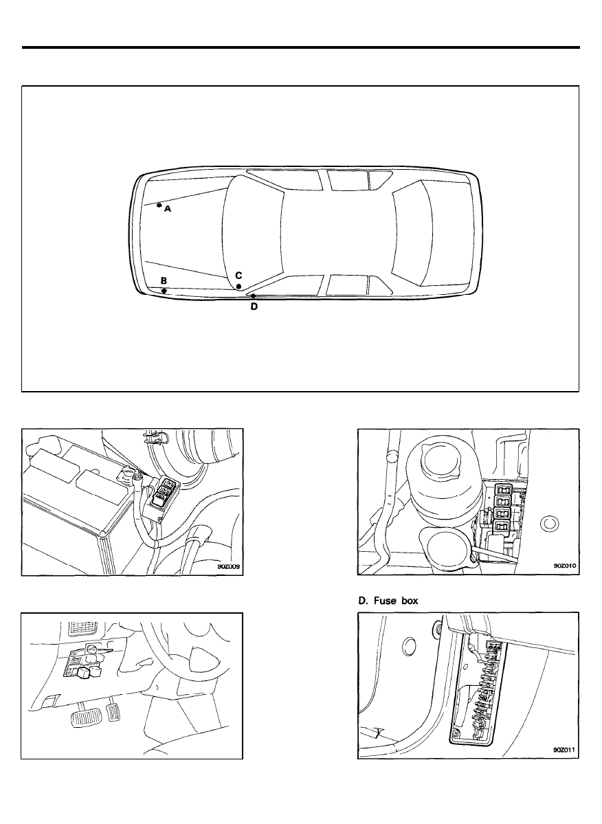
ELECTRICAL COMPONENT LOCATION
FUSIBLE LINK & FUSE
A. Main fusible link
C. Relay box
B. Sub-fusible link
9 0 - 9
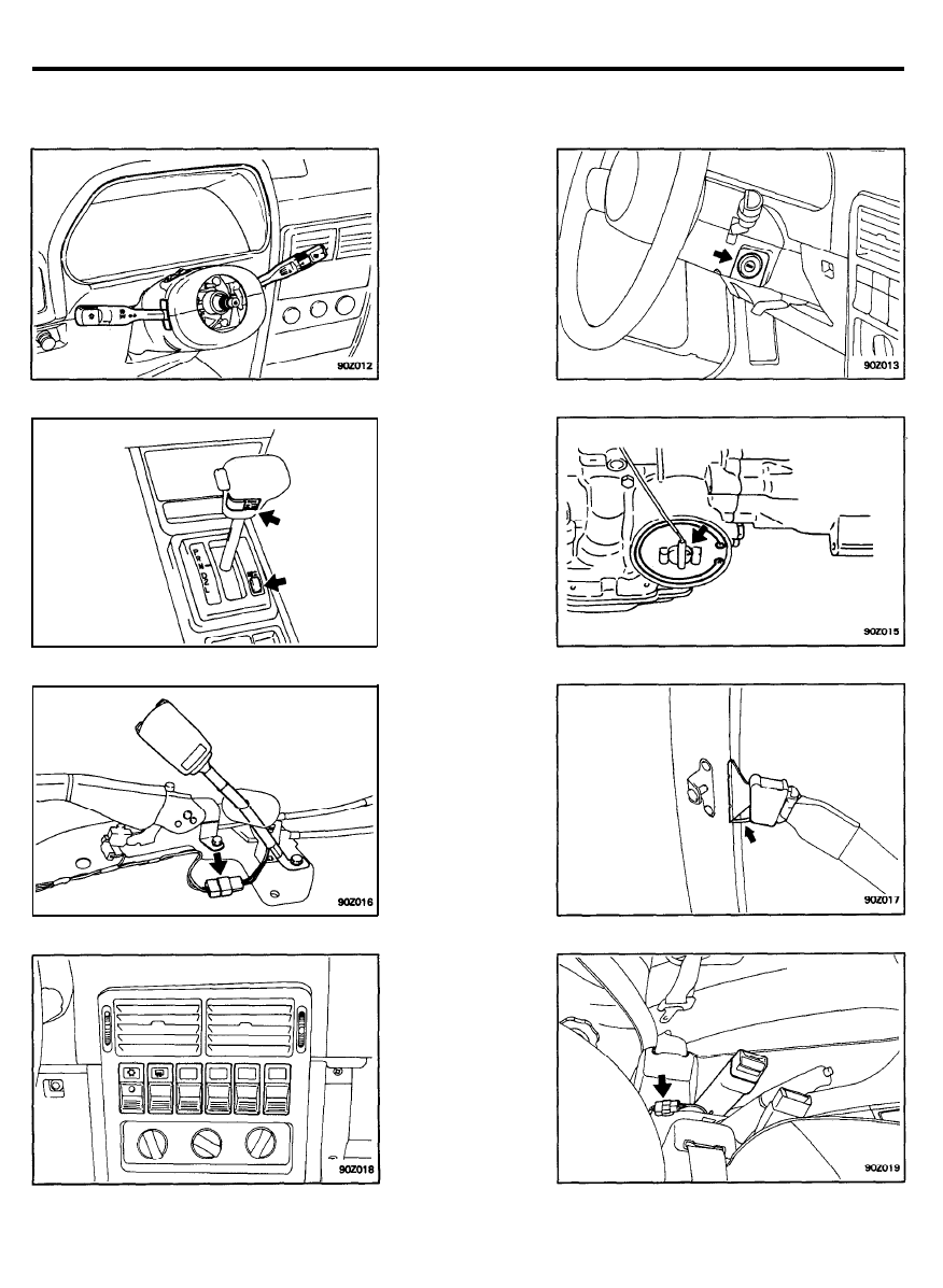
ELECTRICAL COMPONENT LOCATION
SWITCH ES
Multifunction switch
Overdrive switch/Normal economy switch
Seat belt switch (without passive seat belt)
Crash pad mounting switch
Ignition switch
Kick down switch
Seat belt switch (with passive seat belt)
Lap belt switch (with passive seat belt)
9 0 - 1 0
Parking brake switch
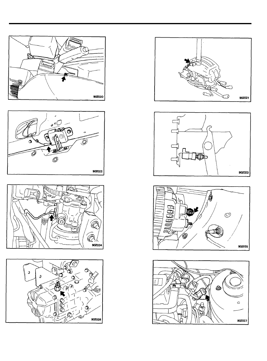
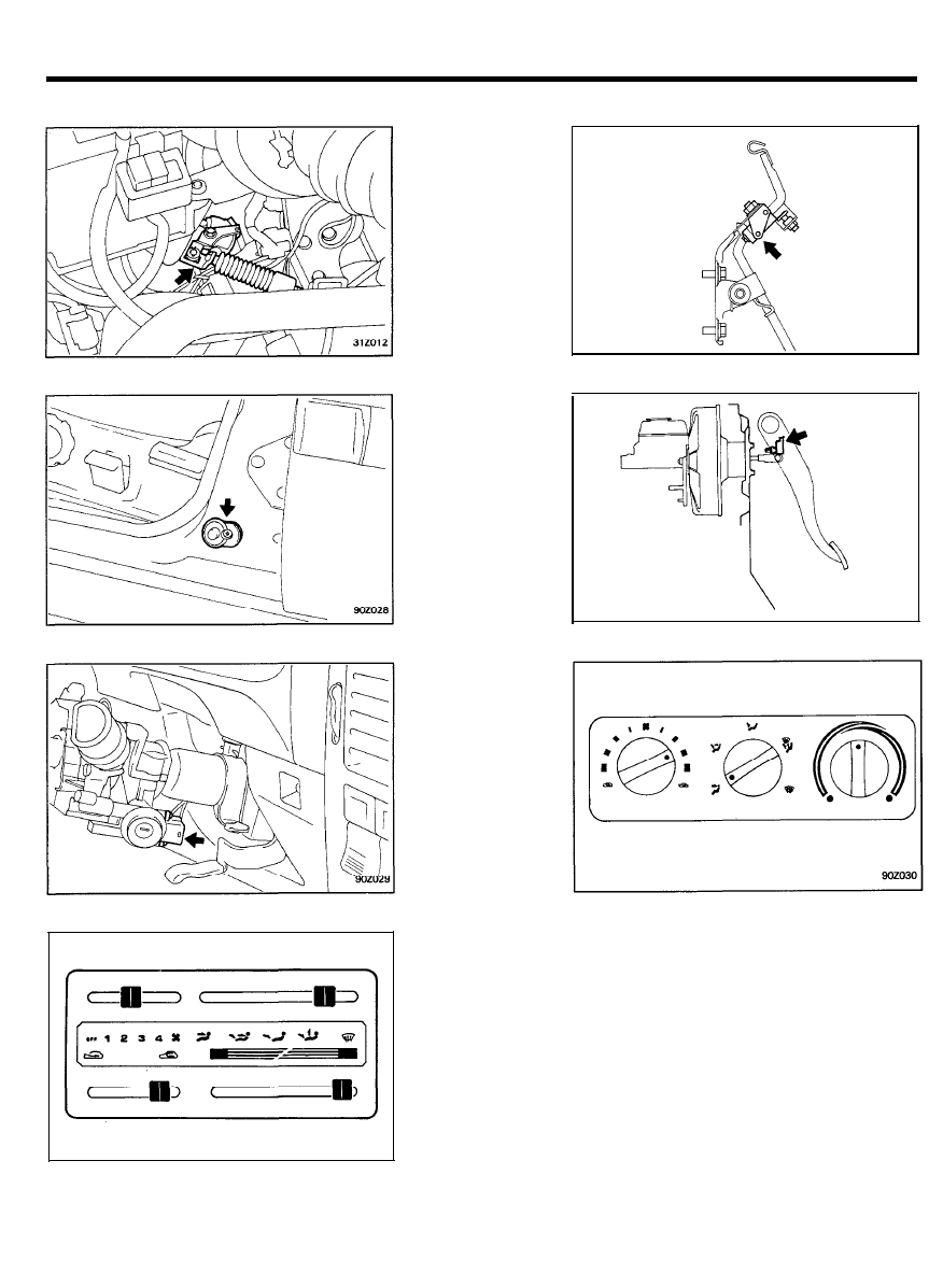
ELECTRICAL COMPONENT LOCATION
P/position switch (with A/T)
Luggage lamp switch
Power steering switch
Back-up lamp switch
Ignition lock switch (with M/T)
Oil pressure switch
Pressure switch (with A/C)
9 0 - 1 1
ELECTRICAL COMPONENT LOCATION
Inhibitor switch (with A/T)
Door switch
Door warning switch
Blower switch (Level type)
Accelerator switch (with A/T)
Stop switch
Blower switch (Rotary type)
9 0 - 1 2
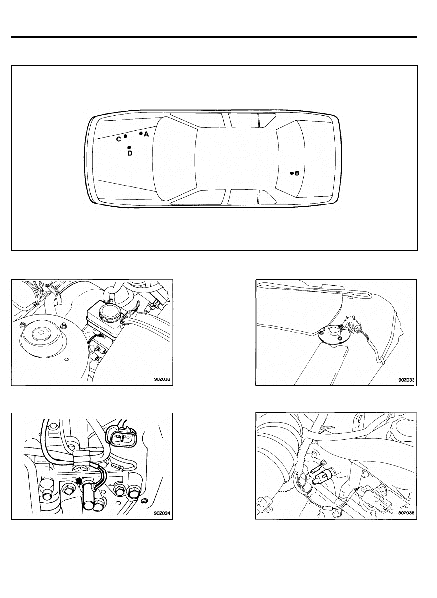
ELECTRICAL COMPONENT LOCATION
S E N S O R S
A. Brake fluid sensor
8. Fuel sender
C. Oil temperature sensor (with KM176-5)
D. Water temperature sender
*For the more accurate location of sensors such as Water Temperature Sensor, Throttle Position Sensor, Crank
Angle Sensor, Motor Position Sensor, Engine Speed Sensor, Air Flow Sensor, EGR Temp. Sensor (USA, California
only), O
2
Sensor, refer to Group “ENGINE”.
9 0 - 1 3
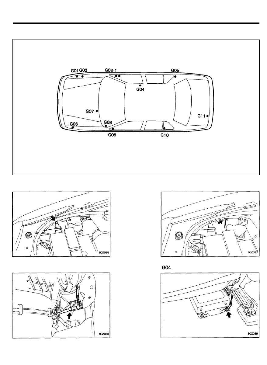
ELECTRICAL COMPONENT LOCATION
G R O U N D P O I N T S
G01 (Multi)
GO2
G03-1 (Multi), G03-2
9 0 - 1 4
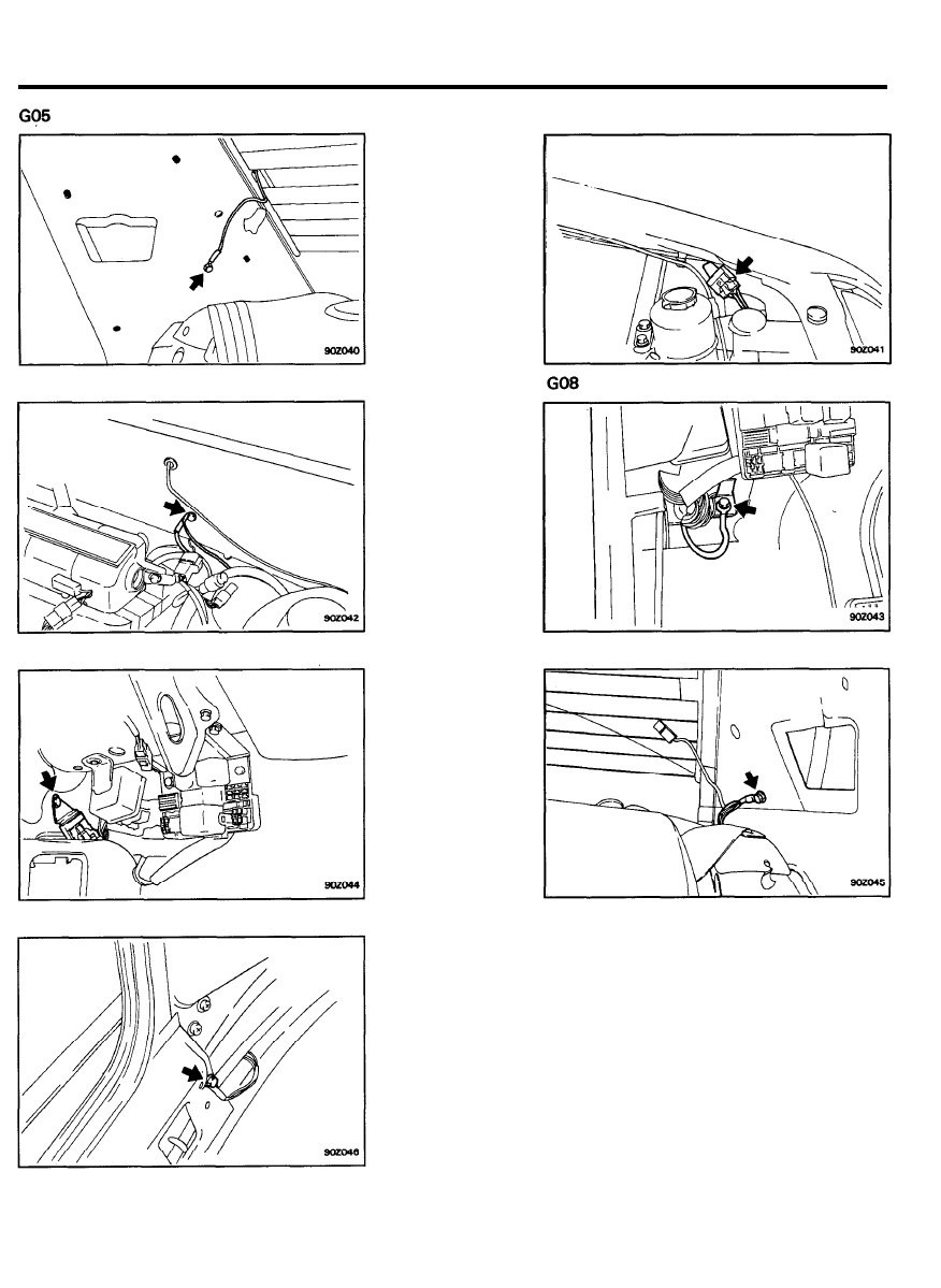
ELECTRICAL COMPONENT LOCATION
GO6 (Multi)
GO7
GO9 (Multi)
G11
G10 (4 Door)
9 0 - 1 5

FUSIBLE LINKS AND FUSES
FUSIBLE LINKS & FUSES
FUSIBLE LINK
SPECIFICATIONS
Item
Main fusible link
Type
Ampere rating
Housing color
Sub-fusible link
Type
Ampere rating & circuit, housing
color
Specification
Screw-up type
50A (Charging circuit)
30A (Radiator & Condenser fan circuit)
5 0 A - R e d
30A-Pink
Located in engine compartment relay box
Connector type
Circuit
Fuse
Item
box
MPI
Head
lamp
IGN
Ampere
rating
50A
20A
30A
30A
Housing
color
Red
Blue
Pink
Pink
INSPECTION
1 . Check for a burnt fusible link with an ohmmeter. (fusible link
must be removed from holder prior to testing)
2. If a fusible link burns out, there is a short or some other
problem in the circuit. Carefully determine the cause and
correct it before replacing the fusible link.
NOTE
The fusible link will burn out within 15 seconds if a higher
current than specified flows through the circuit.
9 0 - 1 6
FUSIBLE LINKS AND FUSES
FUSES
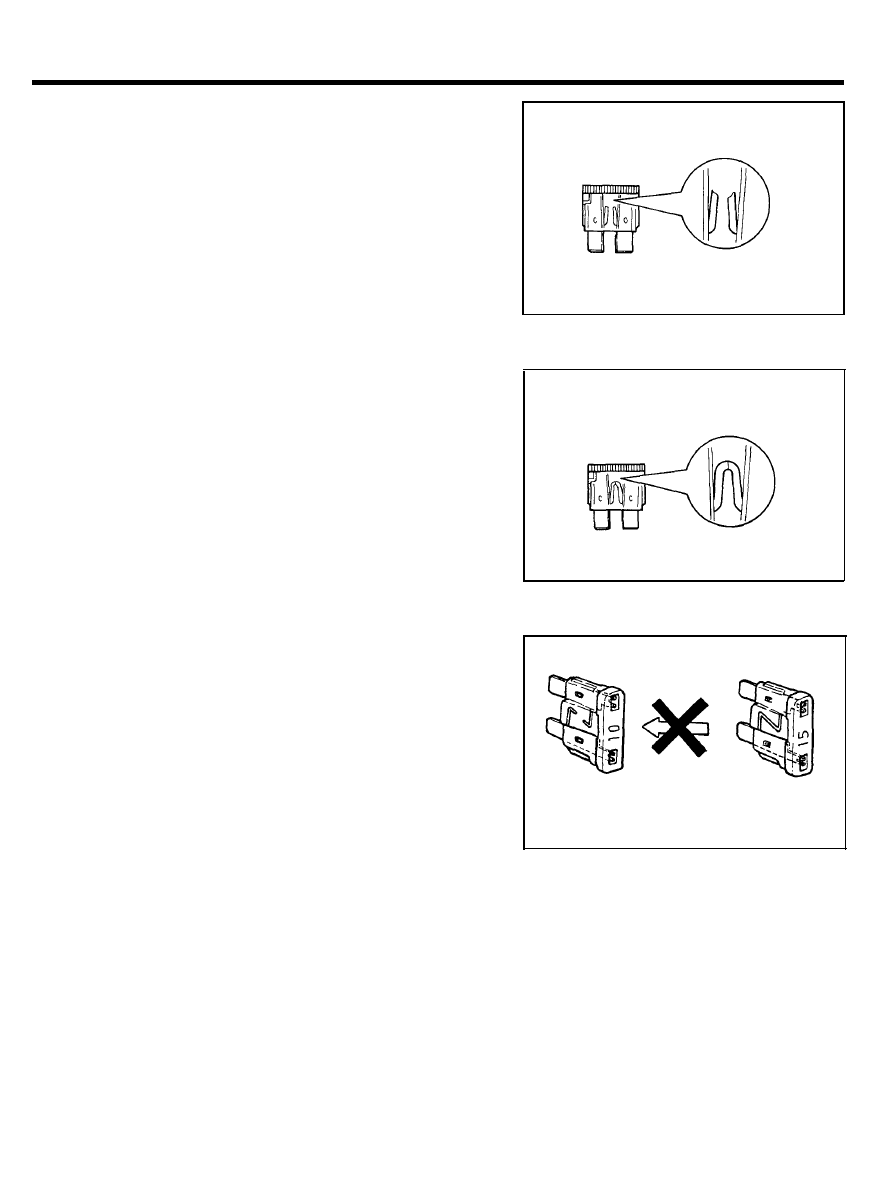
I N S P E C T I O N
When a fuse is blown, there are two probable causes as follows.
Which of the two causes is responsible can be easily determined
by visual check after removing the fuses.
1. Fuse blown due to over-current.
Prior to replacing the fuse with a new one has check the
circuit for short and check the related parts for abnormal
condition.
Only after the correction of such short or abnormal parts,
fuse with same ampere rating should be used as a
replacement.
2. Fuse blown due to repeated current on-off.
Normally, this type of problem occurs after fairly long period
of use and hence is less frequent than the above type.
In this case, you may simply replace with a new fuse of the
same capacity.
CAUTION
A blade type fuses are identified by the numbered value
in amperes.
If the fuse is burnt-out, be sure to replace a fuse with the
same ampere rating. If a fuse of higher capacity than
specified is used parts may be damaged and the danger
of fire also exists.
9 0 - 1 7
IGNITION SWITCH
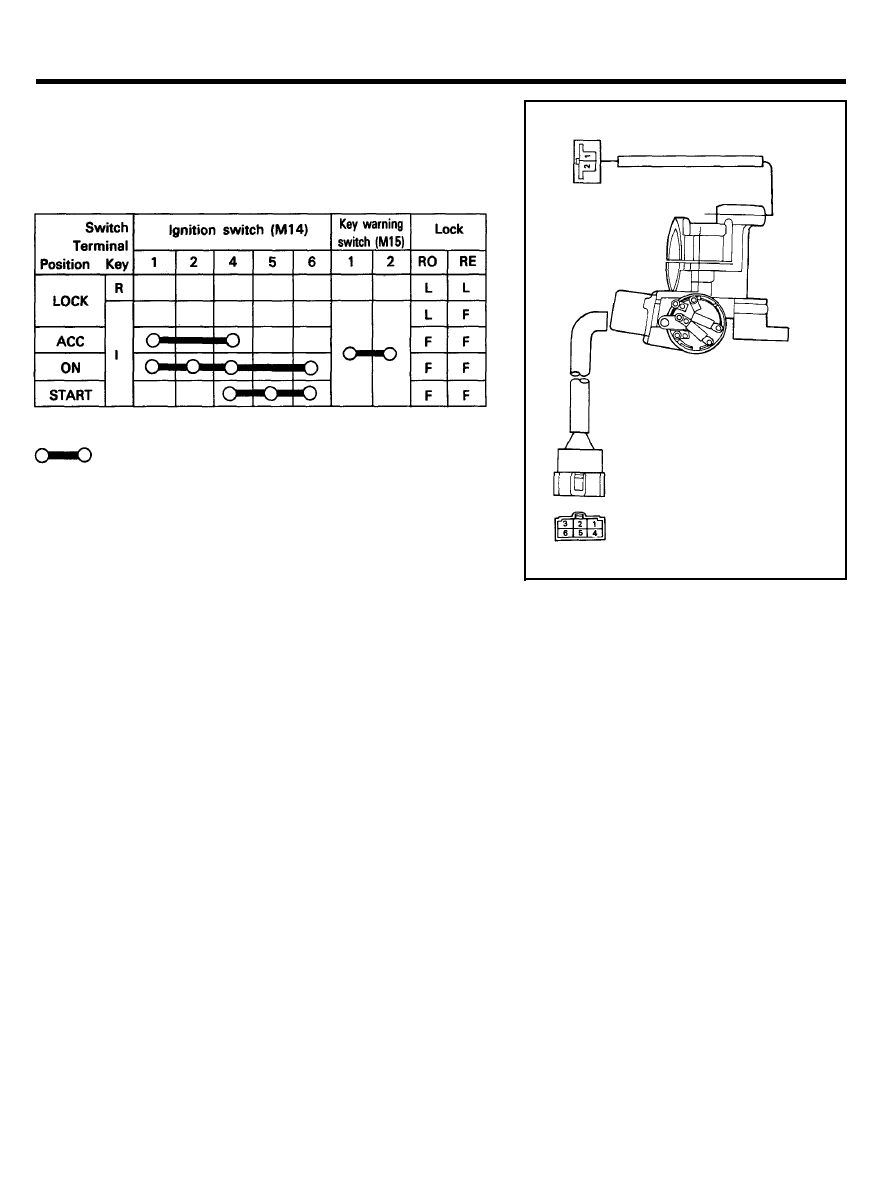
IGNITION SWITCH (WITH KEY WARNING SWITCH)
INSPECTION
1. Remove the connector located under the steering column.
2. Check for continuity between terminals.
NOTE
: indicates that there is a continuity between
terminals.
RO : Round the locking bar, RE : Return the locking bar,
R : Removed, I : Inserted
9 0 - 1 8
MULTIFUNCTION SWITCH
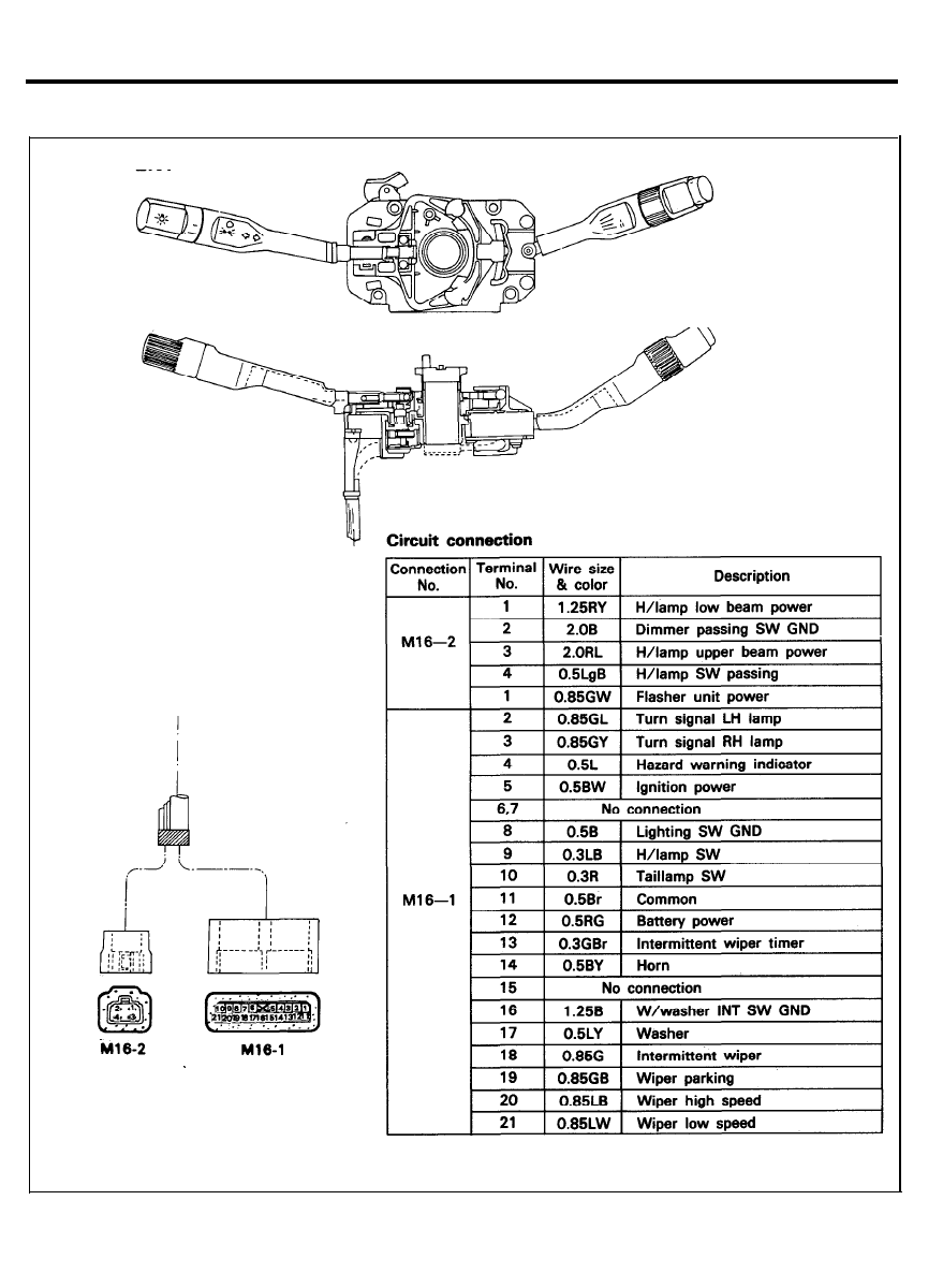
MULTIFUNCTION SWITCH
COMPONENT
9 0 - 1 9
MULTIFUNCTION SWITCH
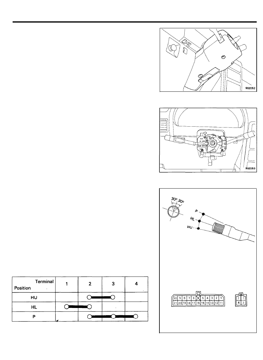
R E M O V A L A N D I N S T A L L A T I O N
1. Disconnect the battery ground cable.
2. Remove the steering wheel.
3. Remove the steering column shroud.
4. Disconnect the harness connector.
5. Remove 3 straps.
6. Remove the multifunction switch ass’y by loosening 4
screws.
7. Installation is the reverse order of the removal procedure.
INSPECTION
With the multifunction switch in each position, make sure that
continuity exists between terminals below.
Lighting switch (Connector No.: M16-1)
Dimmer and passing switch (Connector No.: M16-2)
9 0 - 2 0
MULTIFUNCTION SWITCH
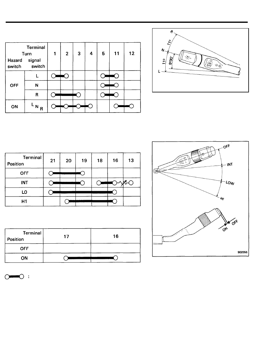
Turn signal and hazard warning switch (Connector No.:
M 1 6 - 1 )
L : Left position
N : Neutral position
R : Right position
Wiper switch (Connector No.: M16-1)
Washer switch (Connector No.: Ml 6-1)
NOTE
indicates that there is continuity between
terminals.
9 0 - 2 1

INSTRUMENTS AND WARNING SYSTEM
INSTRUMENTS AND WARNING SYSTEM
SPECIFICATIONS
Instrument cluster
Type
Illumination lamps
Illumination color
Indicator and warning lamps
Battery charge
Oil pressure
Door ajar
Check engine
Brake warning
Low fuel
Direction indicator (LH, RH)
Low beam
High beam
Seat belt warning
Hazard
Tail gate (Trunk lid) open
Over-drive OFF
Rear heated
Package type (flexible P.C.B. with push connection)
12V 3.4W x 4, 1.2W x 1
Milky white
Bulb wattage
Illumination color
1.2
Red
1.2
Red
1.2
Red
1.2
Amber
1.2
Red
3.0
Amber
1.2
Green
1.2
Green
3.0
Blue
1.2
Red
1.2
Red
1.2
Red
1.2
Amber
1.2
Amber
9 0 - 2 2
INSTRUMENTS AND WARNING SYSTEM
SERVICE SPECIFICATIONS
Item
Speedometer
Type
Indication tolerance
Specification
Vortex ampere push connection type
Speed (MPH)
10
20 40 55
75 100
Tolerance (MPH)
±1.5
±1.5
±1.5
±1.5
±1.5
±1.5
Speed (km/h)
2 0
40 60 80 100 120
140
160
Tolerance (km/h) +4 +3 +4 +5 +5
+5.5
+5.5
+5.5
0
0 0 0 0 +0.5
+ 0 . 5 + 0 . 5
Tachometer
Type
Indication tolerance
Electronic type
Standard (RPM)
Tolerance (RPM)
1,000
2 , 0 0 0 3 , 0 0 0 4 , 0 0 0 5 , 0 0 0
6 , 0 0 0 7 , 0 0 0
±100
±125
±150
±150
±150
±180
±210
Fuel gauge
Type
Indication
Bimetal (built-in voltage regulator) type
Fuel level
E (Empty)
1 / 2
Scale angle
-30° 0°
Tolerance
±2°24’
±4°
Tolerance when assem-
0 °
bled with fuel sender
- 5 . 6 °
±7.5°
F (Full)
+30°
± 2 ° 2 4
+7.1°
0 °
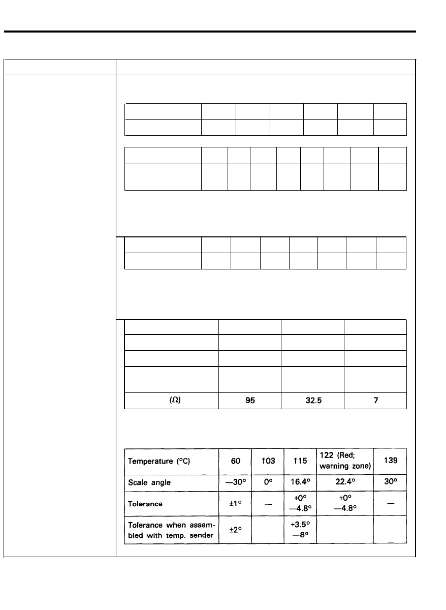
Temperature gauge
Type
Indication
Resistance
Bimetal type
9 0 - 2 3

INSTRUMENTS AND WARNING SYSTEM
TROUBLESHOOTING
Problem
Probable cause
Remedy
Speedometer does not operate
No.17 fuse (10A) blown
Check for short and replace fuse
Speedometer faulty
Check speedometer
Reed switch faulty
Check the switch located within the
speedometer
Wiring faulty
Repair if necessary
Tachometer does not operate
No.17 fuse (10A) blown
Check for short and replace fuse
Tachometer faulty
Check tachometer
Wiring Faulty
Repair if necessary
Fuel gauge does not operate
No.17 fuse (10A) blown
Check for short and replace fuse
Fuel gauge faulty
Check gauge
Fuel sender faulty
Check fuel sender
Wiring faulty
Repair if necessary
Low fuel warning lamp does No.17 fuse (10A) blown
Check for short and replace fuse
not light
Bulb burned out
Replace bulb
Fuel level sensor faulty
Check switch
Wiring or ground faulty
Repair as necessary
Water temperature gauge does
No. 17 (10A) fuse blown
Check for short and replace fuse
not operate
Water temperature gauge faulty
Check gauge
Water temperature sender faulty
Check sender
Wiring or ground faulty
Repair if necessary
Oil pressure warning lamp NO. 17 (10A) fuse blown
Check for short and replace fuse
does not light
Bulb burned out
Replace bulb
Oil pressure sender faulty
Check sender
Wiring or ground faulty
Repair if necessary
Low brake fluid warning lamp
NO. 17 (10A) fuse blown
Check for short and replace fuse
does not light
Bulb burned out
Replace bulb
Brake fluid level warning switch faulty
Check switch
Parking brake switch faulty
Check switch
Wiring or ground faulty
Repair if necessary
Open door warning lamp does
NO. 5 (10A) fuse blown
Check for short and replace fuse
not light
Bulb burned out
Replace bulb
Door switch faulty
Check switch
Wiring or ground faulty
Repair if necessary
9 0 - 2 4
INSTRUMENTS AND WARNING SYSTEM
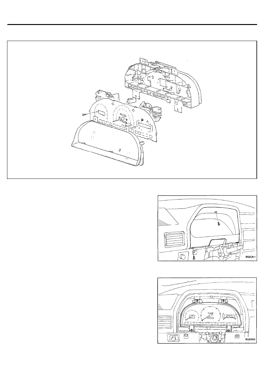
INSTRUMENT CLUSTER
C O M P O N E N T S
R E M O V A L A N D I N S T A L L A T I O N
1.
2.
3.
4.
5 .
Disconnect the battery ground cable.
Remove three retaining screws at the facia panel and pull
panel rearward.
Remove four screws retaining cluster and carefully pull
rearward enough to disengage speedometer cable.
Carefully pull cluster away from instrument panel and
disconnect the cluster wiring from the printed circuit board.
Installation is the reverse order of removal.
9 0 - 2 5
INSTRUMENTS AND WARNING SYSTEM
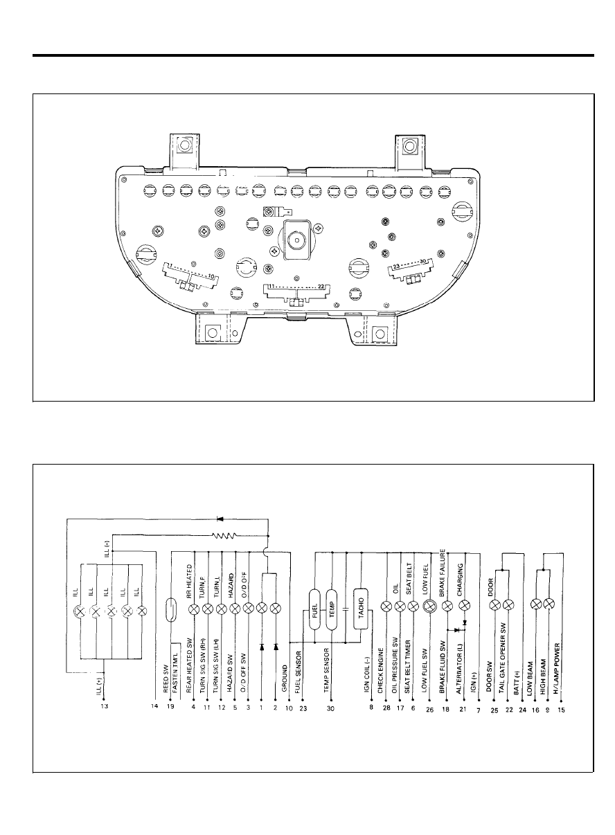
P R I N T E D C I R C U I T B O A R D
C I R C U I T D I A G R A M
9 0 - 2 6
INSTRUMENTS AND WARNING SYSTEMS
SPEEDOMETER AND SPEEDOMETER CABLE
Speedometer inspection (under in-vehicle)
1.
Using a speedometer tester, ensure that any indication error
is within tolerance limits.
NOTE
It should be noted that the excessive tire wear and tire
over or under-inflation will cause indication errors.
Speed (MPH)
10 20 40 55 75
100
Tolerance (MPH) ±1.5
±1.5
±1.5
±1.5
±1.5
±1.5
Speed (km/h)
20 40 60 80 100 120 140 160
Tolerance (km/h) +4 +3 +4 +5
+5 +5.5 +5.5 +5.5
0 0 0 0
0 +0.5 +0.5 +0.5
2.
Check the speedometer for pointer fluctuation and abnormal
noise.
NOTE
Pointer fluctuations can be caused by a faulty speed-
ometer cable.
3. Check to see if the odometer is functioning properly.
Speedometer cable inspection
1. Check the cable for kinks, bents or damages in routing.
If the conditions are severe, replace cable.
2.
After disconnecting cable, check the core for kinks, burrs or
bent tips.
NOTE
When installing a cable, it is necessary that extra care
should be taken to verify that the stopper of the cable is
fitted properly into the speedometer groove and the cable
is routed properly to eliminate any kinks.
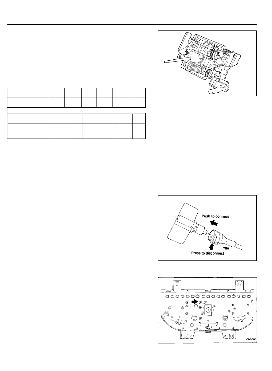
Reed switch inspection
1. Remove the instrument cluster.
2. Use an ohmmeter to check circuit repeats on-off between
terminals while the speedometer drive shaft completes a
turn.
9 0 - 2 7
INSTRUMENTS AND WARNING SYSTEMS
T A C H O M E T E R
On-vehicle inspection
1. Connect the multi-use tester to the diagnosis connector in
the fuse box, or install a tachometer for the tune-up test.
2.
With engine starting, compare the readings of the tester with
that of the tachometer.
If the multi-use tester is used, press code No.22 and read
the rpm.
Replace tachometer if difference is excessive.
Standard (RPM)
1,000 2,000 3,000 4,000 5,000 6,000 7,000
Tolerance (RPM) ±100 ±125 ±150 ±150 ±150 ±180 ±210
FUEL GAUGE AND FUEL SENDER
Fuel gauge operation check (in-vehicle)
1.
Raise the vehicle and disconnect the fuel sender connector
from fuel sender.
2.
Ground the harness side connector (terminal 2) via 12V, 3.4
W bulb.
3. Turn the ignition switch to the ON position.
4. Check to be sure that the test bulb flashes and that the
indicator moves graually to the “F” position.
Fuel gauge inspection
1. Remove the instrument cluster.
2. Measure the resistance between terminals.
Standard resistance :
NOTE
If the resistance value is extremely low, there may be a
short in the coil; if it is extremely high, there may a broken
wire or some other problems in the coil.
9 0 - 2 8
INSTRUMENTS AND WARNING SYSTEMS
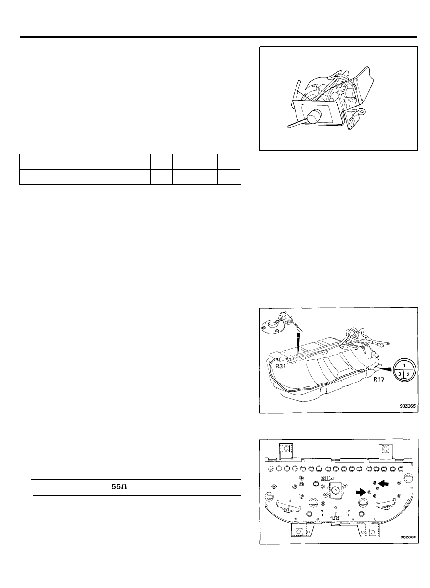
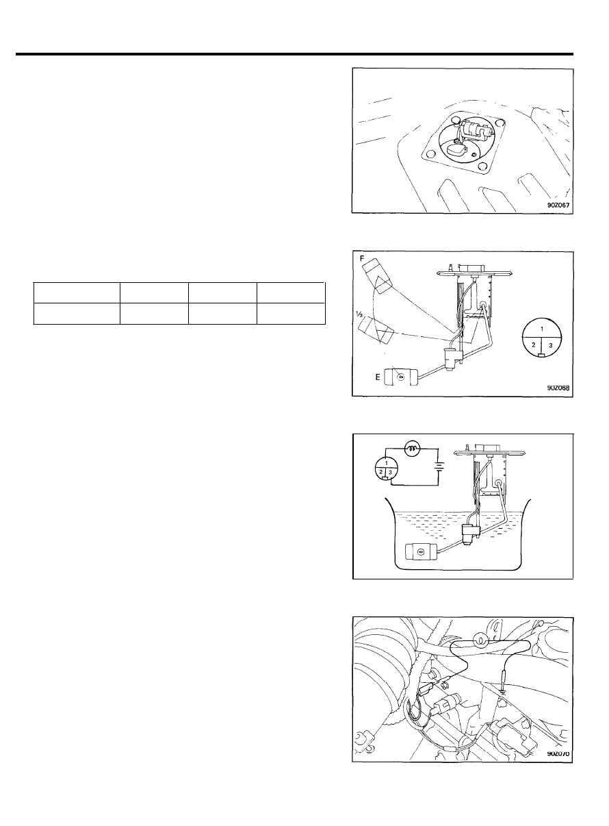
Fuel sender inspection
1. Remove the luggage covering carpet and spare tire.
2. Remove the fuel tank cover retaining screws.
3. Remove the fuel sender assembly.
4. Using an ohmmeter,
measure the resistance between
terminals 2 and 3 at each float level.
Float position
E
1 / 2
F
Resistance R
110±7
32.5±4
3±2
5. Check that resistance changes smoothly when the float is
moved to “E” or “F”.
Low fuel lebel sensor inspection
1. Connect the sender with a test lamp (12V, 3.4W) to the
battery and immerse it in the water.
2. The lamp should be off while thermistor is beneath the
water, and should illuminate when the sender is taken out
of the water.
NOTE
If there is a malfunction, replace the fuel sender as an
assembly.
CAUTION
After completing this test, wipe the sender dry and install
it in the fuel tank.
W A T E R T E M P E R A T U R E G A U G E A N D
S E N D E R
Water temperature gauge operation check (in-vehicle)
1. Remove the harness connector from water temperature
sender located in engine compartment.
2. Ground the harness side connector via 12V, 3.4W bulb.
3. Turn the ignition switch to ON position.
4. Check to be sure that the test bulb flashes and that the
indicator moves.
9 0 - 2 9
INSTRUMENTS AND WARNING SYSTEMS
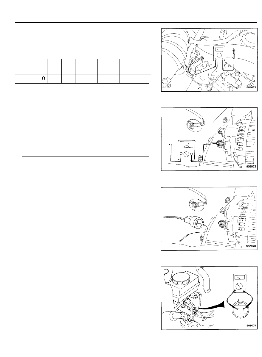
Water temperature sender inspection
Using on ohmmeter, measure the resistance between terminal
and ground.
If the resistance is out of specification, replace the sender.
Temperature
50
60
70
115
120
122
°C (°F)
( 1 1 2 ) ( 1 4 0 ) ( 1 5 8 )
(239) (248) (252)
Resistance
230
155
104±13.5
23.8±2.5
21
19.5
O I L P R E S S U R E S W I T C H A N D W A R N I N G
L A M P
Oil pressure switch inspection
1.
Pull out the connector from the oil pressure switch located
at the cylinder block.
2.
Ensure that there is continuity between switch terminal and
ground under condition of pressure below.
Switch ON pressure .....................................................................
0.3 ± 0.1 kg/cm
2
(29.4 ± 9.8 kPa, 4.3 ± 1.4 psi)
Oil pressure warning lamp inspection
1. Pull out the connector from the oil pressure switch.
2. Ground the harness side connector.
3.
Ensure that the oil pressure warning lamp lights when the
ignition switch is turned ON.
BRAKE FLUID LEVEL WARNING SWITCH
A N D L A M P
Brake fluid level warning switch inspection
1.
Remove the connector from the switch located at brake fluid
reservoir.
2.
Ensure that the continuity exists between switch terminals
1 and 2 while pressing down the switch (float) with a rod.
9 0 - 3 0
INSTRUMENTS AND WARNING SYSTEMS
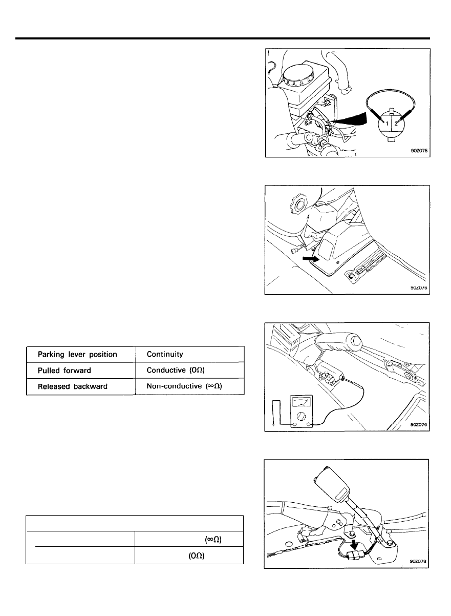
Brake fluid level warning lamp inspection
1.
2.
3.
4.
5.
Start the engine.
Release the parking brake lever to the original position.
Disconnect the connector of the brake fluid level warning
switch.
Ground the connector at the harness side.
Ensure that the warning lamp lights.
Parking brake switch inspection
1. Remove the rear console assembly.
2.
3.
Disconnect the connector of parking brake switch.
Check continuity between terminal and body ground.
S E A T B E L T W A R N I N G S W I T C H A N D
Seat belt switch inspection
1. Disconnect the connector from the switch.
2. Check for continuity between terminals.
Seat belt condition
Continuity
Fastened
Non-conductive
Non fastened
Conductive
9 0 - 3 1
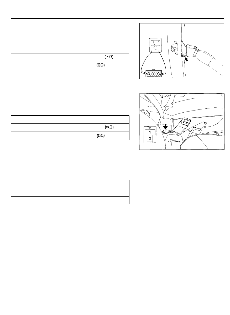
INSTRUMENTS AND WARNING SYSTEMS
Passive seat belt switch inspection
1. Disconnect the connector from the switch.
2. Check for continuity between terminals.
Seat belt condition
Continuity
Fastened
Non-conductive
Non fastened
Conductive
Lap belt switch inspection (with passive seat)
1. Remove the connector from the switch.
2. Check for continuity between terminals.
Seat belt condition
Continuity
Fastened
Non-conductive
Non fastened
Conductive
Seat belt warning lamp inspection
With the ignition switch turned ON, ensure that the lamp glows.
Seat belt condition
Warning lamp
Fastened
Not fastened
Off
Glows for about six seconds
9 0 - 3 2

LIGHTING SYSTEM
LIGHTING SYSTEM
SPECIFICATION
Lamps
Headlamp
Front turn signal lamp (located in headlamp)
Front side marker and reflex reflector lamp
Rear combination lamp
Tail and stop lamp
Back-up lamp
Rear turn signal lamp
Rear side marker and reflex reflector
(common with tail and stop lamp)
Licence plate lamp
Luggage lamp
High mounted stop lamp
Overhead console lamp (with sunroof)
Courtesy lamp (with sunroof)
Flasher unit
Turn signal blinking frequency
Hazard warning blinking frequency
6 5 / 4 5 W
2 8 / 8 W
4 W
2 7 / 8 W
27 W
27 W
2 7 / 8 W
8 W
5 W
17 W
10 W
10 W
85 ± 10 C/M at 12.8V
80 ± 12 C/M at 12.8V
9 0 - 3 3

LIGHTING SYSTEM
TROUBLESHOOTING
Problem
Possible cause
Remedy
One lamp only does not light
Bulb burnt out
Replace bulb
(all exterior)
Socket, wire or ground faulty
Repair as necessary
No headlamps light
Sub-fusible link (30A) blown
Replace sub-fusible link
Headlamp relay faulty
Check relay
Lighting switch faulty
Check switch
Wiring or ground faulty
Repair as necessary
Tail, parking and licence lamp
Tail fuse blown (No.13 and/or No.14)
Replace fuse and check for short
do not light
Fusible link blown (30A)
Replace fusible link
Taillamp relay faulty
Check relay
Lighting switch faulty
Check switch
Wiring or ground faulty
Repair as necessary
Stop lamps do not light
Stop fuse (No.4) blown
Replace fuse and check for short
Stop lamp switch faulty
Adjust or replace switch
Wiring or ground faulty
Repair as necessary
Stop lamps stay on
Stop lamp switch faulty
Adjust or replace switch
Instrument lamps do not light
Lamp control rheostat faulty
Check rheostat
(taillamps light)
Wiring or ground faulty
Repair as necessary
Turn signal does not flash on
Bulb burnt-out
Replace bulb
one side
Turn signal switch faulty
Check switch
Wiring or ground faulty
Repair as necessary
Turn signal does not operate
Turn signal fuse (No.17) blown
Replace fuse and check for short
Turn signal flasher faulty
Check flasher
Turn signal switch faulty
Check switch
Wiring or ground faulty
Repair as necessary
Hazard warning lamps do not
Sub-fusible link (50A) blown
Replace fusible link
operate
Hazard fuse (No.3) blown
Replace fuse and check for short
Turn signal flasher faulty
Check flasher
Hazard switch faulty
Check switch
Wiring or ground faulty
Repair as necessary
Flasher rate too slow or too fast
Lamps are of a wattage smaller or
Replace lamps
larger than is specified for use
Defective flasher unit
Replace unit
Backup lamps do not light
Back up fuse (No.17) blown
Check for short, replace fuse
Back up lamp switch faulty
Check switch
Damaged wiring or poor grounding
Repair as necessary
9 0 - 3 4
LIGHTING SYSTEM
HEADLAMP AIMING
PRE-AIMING INSTRUCTIONS
1.
2.
3.
4.
5.
6.
7.
8.
9.
Test dimmer switch operation.
Observe operation of high beam indicator light mounted in
the instrument cluster.
Inspect for badly rusted of faulty headlamp assemblies.
These conditions must be corrected before a satisfactory
adjustment can be made.
Place the vehicle on a level floor.
Bounce the front suspension through three (3) oscillations
by applying body weight to hood or bumper.
Check and correct tire inflation pressures.
Rock vehicle sideways to allow vehicle to assume its normal
position.
If the fuel tank is not full, place a weight in the trunk of the
vehicle to simulate the weight of a full tank.
There should be no other load in the vehicle other than driver
or substituted weight of approximately 75 kg (165 Ibs.) placed
in driver’s position.
10. Thoroughly clean the headlamp lenses.
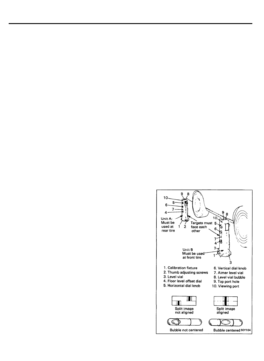
C O M P E N S A T I N G T H E A I M E R S F O R
FLOOR SLOPE
The floor level offset dial must coincide with the floor slope for
accurate aiming. Calibration fixtures are included with the
aimers.
1.
2.
3.
4.
5.
6.
Attach one calibration fixture to each aimer. Fixtures will
easily snap into position on the aimer when properly
positioned.
Place aimers at the center line of each wheel on one side
of vehicle. Unit A must be placed at the rear wheel with the
target facing forward. Unit B must be placed at the front
wheel with the target facing rearward.
Adjust the thumb screw on each calibration fixture by
turning either clockwise or counter-clockwise until the level
vial bubble registers in a centered, level position.
Look into the top port hole of Unit A. Turn horizontal knob
until split image is aligned.
Transfer the plus of minus reading indicated on the
horizontal dial to floor level offset dial on each aimer. Press
floor level dial inward to set reading.
Remove the calibration fixtures from both units.
9 0 - 3 5
LIGHTING SYSTEM
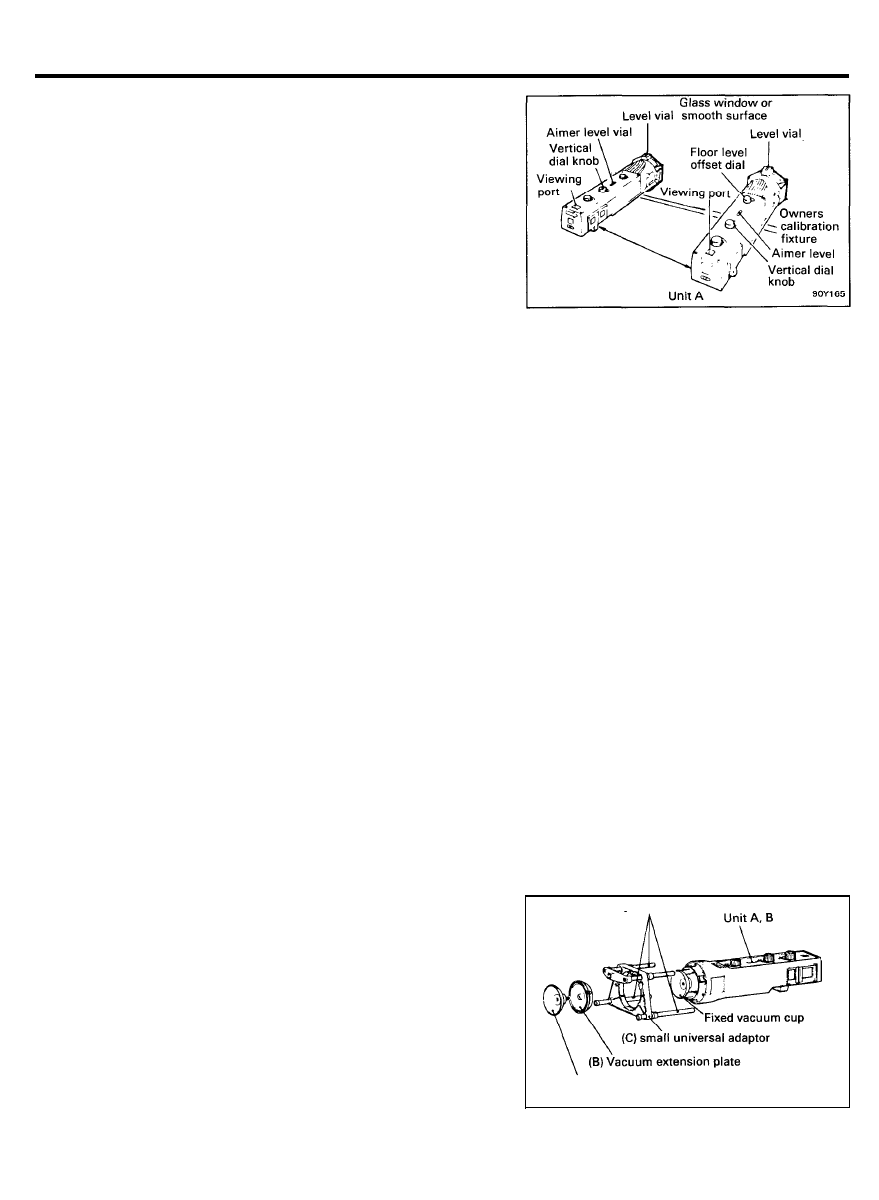
T I M I N G A I M E R C A L I B R A T I O N
1.
Turn the thumb adjusting screw on each calibration fixture
until it is approximately the same distance as the supporting
posts.
2.
Attach the calibration fixtures to each unit with level vials
3.
4.
5.
on top.
Locate the true vertical plate glass window or smooth
surgace and secure aimers three to five feet apart so split
image targets can be located in the viewing ports.
Set the floor level dial to zero.
6.
Rotate thumb adjusting screws on each calibration fixture
until level vials on fixtures are centered.
With both calibration level vials centered, turn vertical dial
knobs on each aimer until aimer level vials are centered. If
aimer vertical dial pointers read between 1/2 up and 1/2
down, aimers are within allowable vertical tolerance,
Recalibrate units if beyond these limits.
Vertical dial pointer reading (on each aimer)1/2 up to 1/2
down
7.
Adjust horizontal dial knob on each aimer until split image
targets align. If aimer horizontal dial pointers read between
1 left and 1 right, the aimers are within allowable tolerance
limits. Recalibrate units if beyond these limits.
The aimer calibration may be off due to extended use.
Calibration fixtures used in conjunction with the aimers can be
used to check and adjust the aimer.
Horizontal dial pointer reading (on each aimer) 1 left to 1 right
MOUNTING AIMERS
Adjustable rod
1. Remove the calibration fixture from the each unit.
2. As shown in the figure, install the articulating vacuum cup
assembly (A), vacuum extension plate (B) and small universal
adapter (C) to each unit.
3. Marke the length of the adjustable rod as shown in the
figure.
(A) Articulating vacuum cap assembly
9 0 - 3 6
LIGHTING SYSTEM
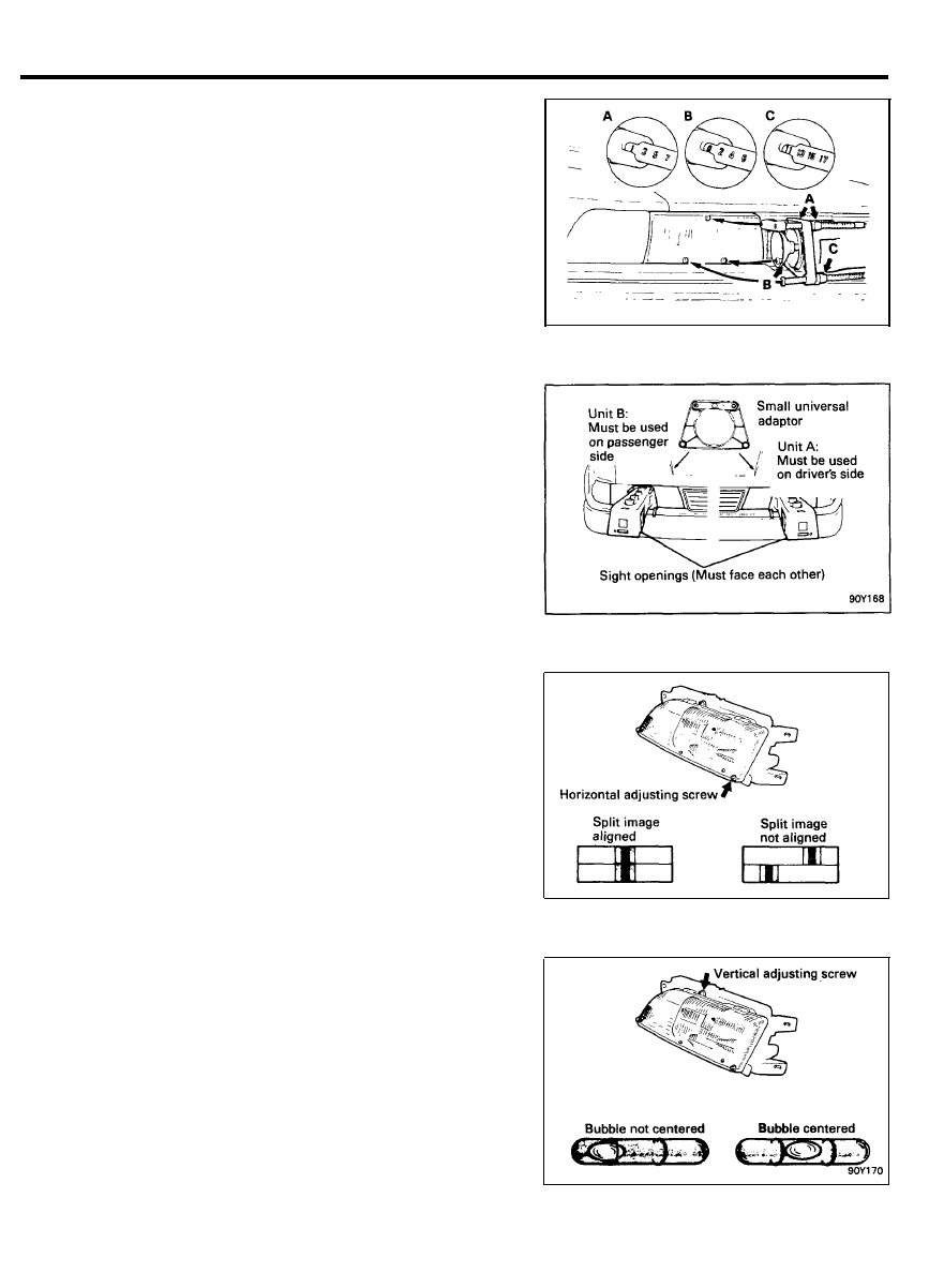
4. Position the aimers on the headlamps pushing the piston
handle forward, engaging the rubber suction cup. Imme-
diately pull back the piston handle until it locks in place.
NOTE
Steel inserts are molded into position on the adapter to
insure accuracy. These inserts must be in contact with the
three guide points on the lamps when the aimers are
properly positioned.
H O R I Z O N T A L A D J U S T M E N T
1. Set the horizontal dial to zero.
2.
Check to see that the split image target lines are visible in
the viewing port. If necessary, rotate each aimer slightly to
locate the target.
3.
Turn the horizontal screw on the side of the headlamp until
the split image of target line appears in the mirrors as one
solid line. To remove “backlash”, make the final adjustment
by turning adjusting screw in a clockwise direction.
4. Repeat the last three steps on the apposite headlamp.
V E R T I C A L A D J U S T M E N T
1. The vertical dial should be set at zero. (For passenger
vehicles,
“0” setting is generally required. For special
settings, consult local state laws.
2. Turn the vertical adjusting screw until the level bubble is
centered between the lines.
3. Repeat the last two steps on the opposite headlamp.
4.
Re-check the target alignment on both aimers and readjust
the horizontal aim if necessary.
5.
Remove aimers by pressing “vacuum release” button located
on the piston handle.
9 0 - 3 7
LIGHTING SYSTEM
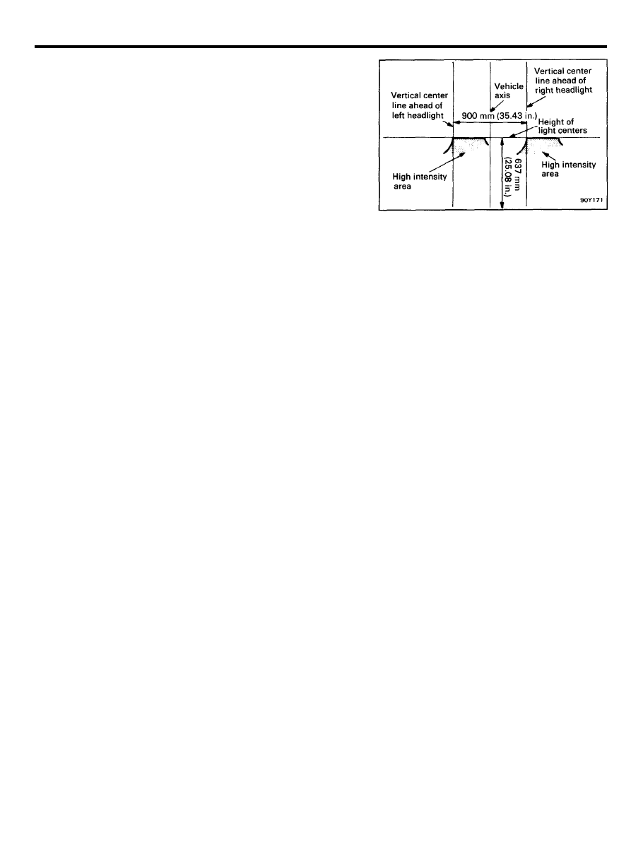
A I M I N G W I T H S C R E E N
Headlamp aiming preparation
Place the vehicle on a level floor, 7.6 m (25 feet) from the aiming
screen or a light-colored wall.
1.
Position a vertical place of tape so that it is aligned with the
vehicle center line.
2. Position a horizontal tape with reference to the center line
of the headlamp.
3. Position a vertical piece of tape on the screw for vertical
adjustment, adjust side screw for horizontal adjustment.
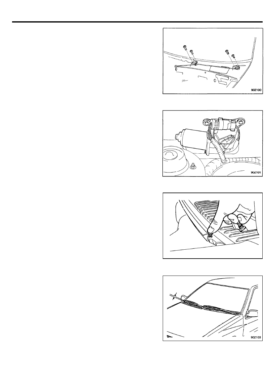
Visual headlamp adjustment
1.
A properly aimed low beam will appear on the aiming screen
7.6 m (25 feet) in front of the vehicle. The shaded area as
shown in the illustration indicates a high intensity zone.
2. Adjust the low beam headlamps to match the low beam
pattern of the right and left headlamps.
NOTE
If the visual headlamp adjustment at low beam is made,
the adjustment at high beam is not necessary.
9 0 - 3 8
LIGHTING SYSTEM
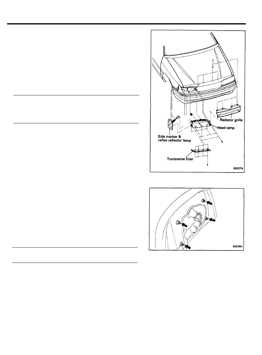
H E A D L A M P
Removal and installation
1.
Remove the radiator grille.
2.
Remove the side marker and reflex reflector lamp ass’y.
3.
Disconnect the headlamp connector.
4.
Remove the headlamp assembly with transverse filler.
5.
Disconnect the head lamp from transverse filler.
6.
Installation is the reverse order of removal procedure.
Tightening torque
Radiator grill mounting
2-3 N.m (20-30 kg.cm, 1.5-2.2 Ib.ft)
Head lamp mounting
3-5 N.m (30-50 kg.cm, 2.2-3.6 Ib.ft)
R E A R C O M B I N A T I O N L A M P
Removal and installation
1. Remove the trunk inner trim.
2. Disconnect the harness connector.
3. Remove the rear combination lamp assembly by loosening
the 4 nuts.
4. Installation is the reverse order of removal procedure.
Tightening torque
Rear combination lamp mounting
2.0-2.5 Nm (20-25 kg.cm, 1.4-1.8 Ib.ft)
9 0 - 3 9
LIGHTING SYSTEM
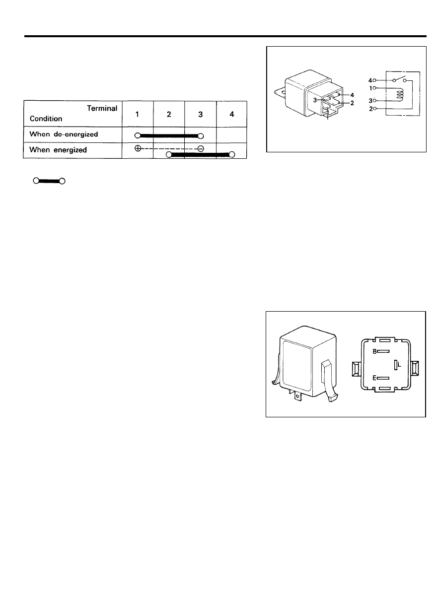
RELAY
Inspection
1. Remove the headlamp relay and taillamp relay.
2. Check for continuity between the terminals.
NOTE
1.
indicates that there is continuity between the
terminals.
2. indicates power supply connection.
T U R N S I G N A L F L A S H E R U N I T
Inspection
1.
Connect the positive (+) lead from the battery to terminal B
and the negative (-) lead to terminal E.
2.
Connect the two turn signal lamps parallel to each other to
terminal L and E, check that the bulbs turn on and off.
NOTE
The turn signal lamps should flash 75 to 95 times per
minute.
If one of the front or rear turn signal lamps has an open
circuit, the number of flashes will be more than 120 per
minute.
If operation is not as specified, replace the flasher unit.
9 0 - 4 0
LIGHTING SYSTEM
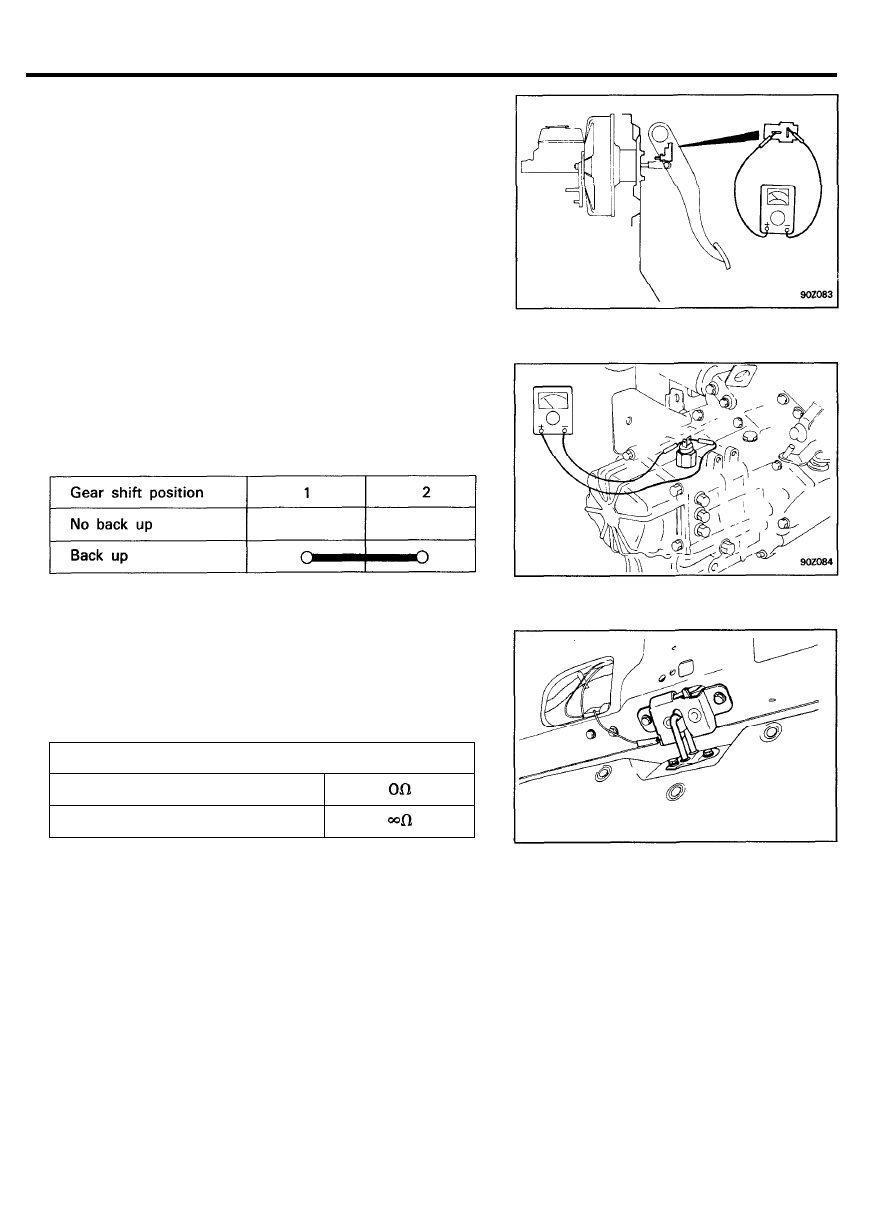
STOP LAMP SWITCH
Inspection
1. Remove the stop lamp switch connector located at brake
pedal bracket.
2.
Make sure that there is a continuity between terminals 1 and
2 when the brake pedal is depressed.
3.
Ensure that no continuity exists between the terminals when
the pedal is released.
B A C K U P L A M P S W I T C H ( M / T )
Inspection
1.
2.
Remove the back up lamp switch connector.
Check for continuity between terminals.
LUGGAGE COMPARTMENT LAMP SWITCH
Inspection
1. Remove the luggage compartment lamp switch connector.
2. Check for continuity between terminal and ground.
Tail gate (trunk lid) condition
Continuity
Opened
Closed
9 0 - 4 1
AUDIO
AUDIO
SPECIFICATIONS
BASE GRADE
Items
Radio
Receiving band
Tuning type
Memory (AM/FM)
Frequency range
AMP
Output power
Volume type
Tape player
Deck type
Reproducing type
M E D I U M G R A D E
Items
Radio
Receiving band
Tuning type
Memory (AM/FM)
Frequency range
AMP
Output power
Volume type
Tape player
Deck type
Eject type
Reproducing type
SPEAKER
C - 3 2 0
H - 5 1 0
A M / F M
E.T.R.
6 / 6
AM : 530-1,610 KHz
FM : 87.9-107.9 MHz
MAX. 18W x 2CH
Rotary
Mechanical
Auto reverse
H - 4 5 5
A M / F M 1 / F M 2
E.T.R.
6/12
AM : 531-1,602 KHz
FM : 87.5-108 MHz
Max. 25W x 2CH
Rotary
Full logic
Key off release
Auto reverse
A M / F M 1 / F M 2
6 / 1 2
AM : 530-1,620 KHz
FM : 87.9-108 MHz
MAX. 20W x 2CH
Full logic
H - 5 5 0
AM : 530-1,710 KHz
FM : 87.9-107.9 MHz
Items
Specifications
Front speaker
Input power
Rated impedance
Distortion
Size
Rear speaker
input power
Rated impedance
Frequency response
NOM. 20W RMS (MAX. 40W RMS)
4 ±
(at 400 Hz, 1V)
MAX. 5% (at 400 Hz, 8W)
10 cm (4 in.)
NOM. 20W RMS (MAX. 40W RMS)
60-20,000 Hz
9 0 - 4 2
AUDIO
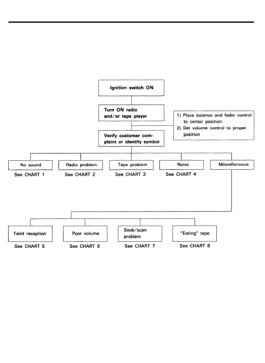
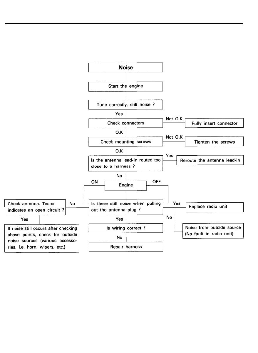
TROUBLESHOOTING
There are 5 areas where a problem can occur: the wiring
harness, radio, cassette tape deck, speaker, and the antenna.
Your job in troubleshooting is to isolate the problem to a
particular area.
9 0 - 4 3
AUDIO
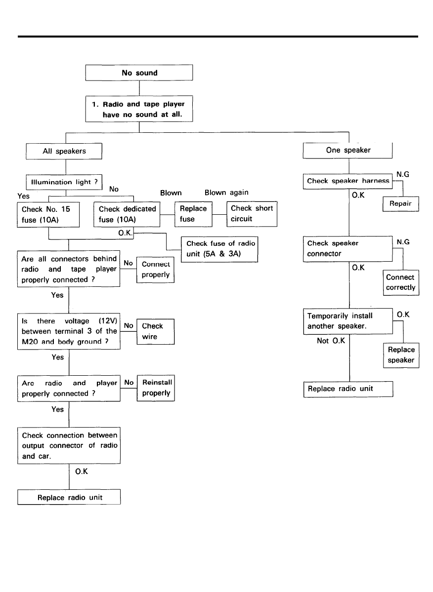
CHART 1
9 0 - 4 4
AUDIO
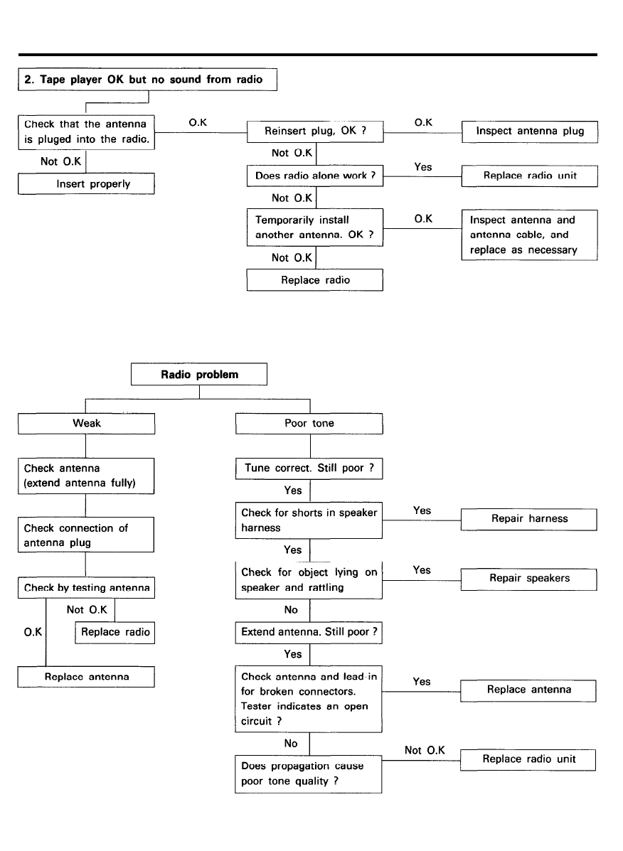
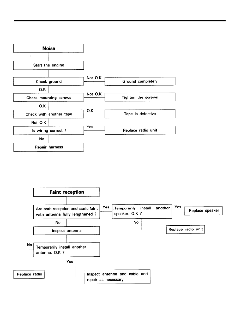
C H A R T 2
9 0 - 4 5
AUDIO
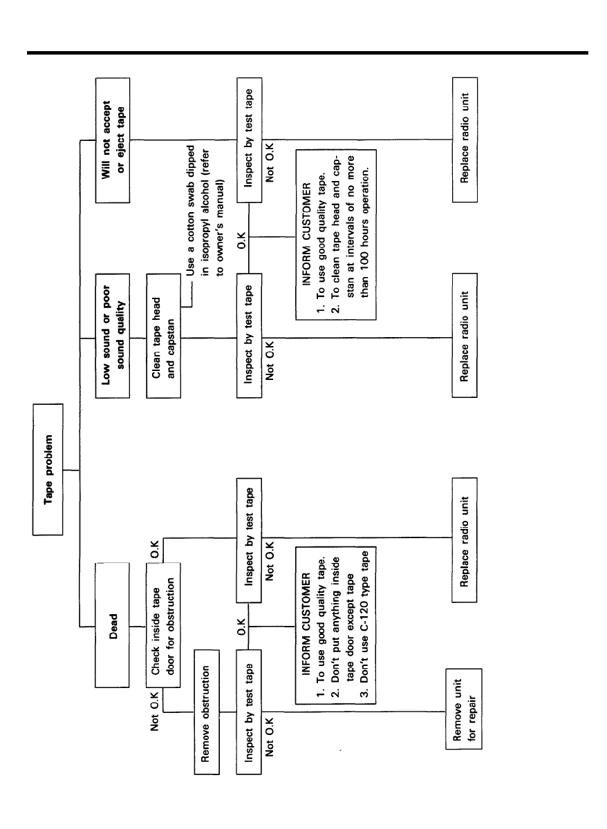
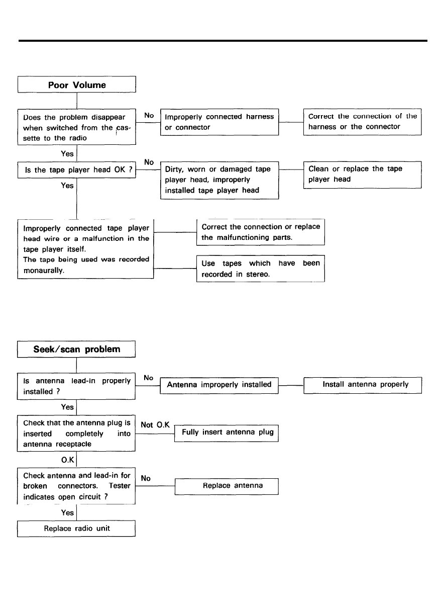
CHART 3
9 0 - 4 6
AUDIO
C H A R T 4
1. RADIO
9 0 - 4 7
AUDIO
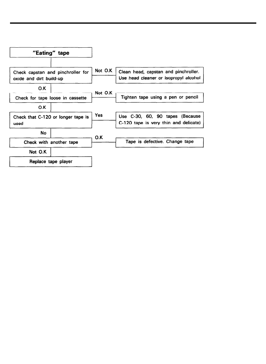
CHART 4 (Continued)
2. TAPE
C H A R T 5
9 0 - 4 8
AUDIO
C H A R T 6
C H A R T 7
9 0 - 4 9
AUDIO
C H A R T 8
9 0 - 5 0
AUDIO
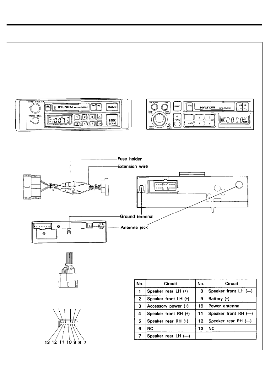
STRUCTURAL VIEW (BASE GRADE)
- F R O N T S I D E -
C - 3 2 0
C - 5 1 0
- B A C K S I D E -
6 5 4 3 2 1
13P Connector (M20)
9 0 - 5 1
AUDIO
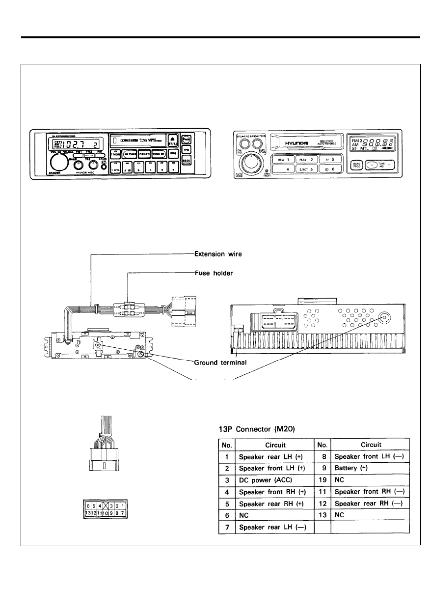
S T R U C T U R A L V I E W ( M E D I U M G R A D E )
- F R O N T S I D E -
H - 5 5 0
H - 4 5 5
- B A C K S I D E -
Antenna jack
9 0 - 5 2
AUDIO
R E M O V A L A N D I N S T A L L A T I O N
1. Remove the ash tray.
2. Remove the mounting screws. (2 EA).
3. Remove the center lower crash pad facia panel.
4. Remove the mounting screws.
5. Remove the radio unit from the mounting bracket.
6. Replace in reverse order of preceding steps.
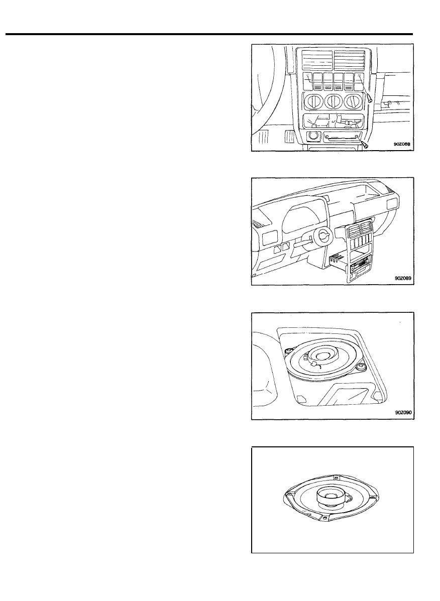
SPEAKER
FRONT SPEAKER
1. Remove the front speaker grille.
2. Remove the speaker mounting bolts.
3. Remove the speaker assembly.
4. Replace in reverse order of the preceding steps.
REAR SPEAKER
1. Remove the rear speaker grille.
2. Remove the speaker mounting bolts.
3. Remove the speaker assembly.
4. Replace in reverse order of the preceding steps.
9 0 - 5 3
AUDIO
SERVICE ADJUSTMENT PROCEDURES
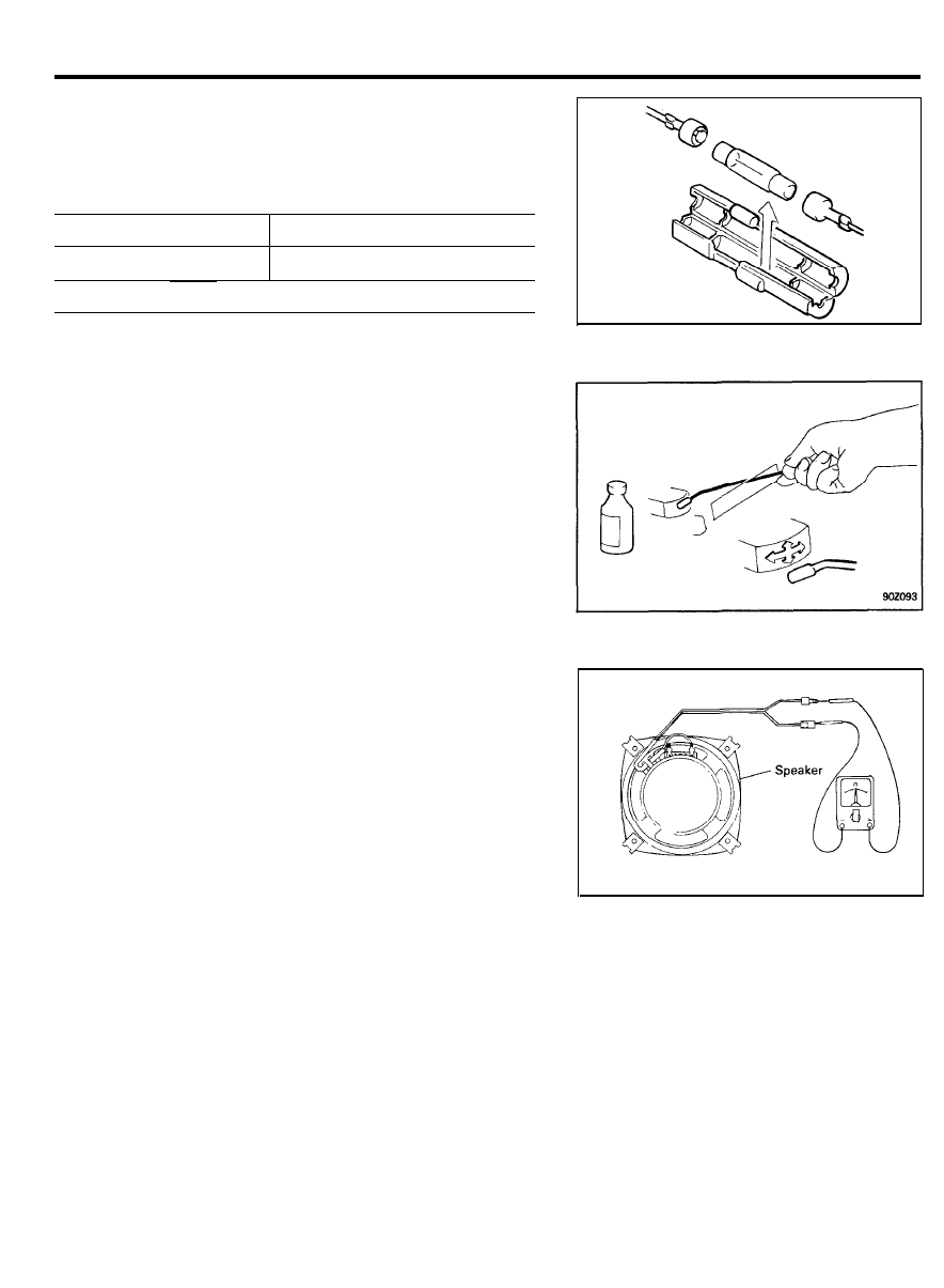
FUSE REPLACEMENT
Make sure of using the specified fuse when marking a
replacement.
Audio unit
Permissible current
BASE GRADE
3A (ACC)
MEDIUM GRADE
5A (ACC) & 3A (B+)
CAUTION
Substituting with a higher capacity fuse or connection without
a fuse may result in damage to the unit.
T A P E H E A D A N D C A P S T A N C L E A N I N G
1.
To obtain optimum performance, clean the head and capstan
as often as necessary, depending upon frequency of use and
tape cleanliness.
2. To clean the tape head and capstan, use a cotton swab
dipped in ordinary rubbing alcohol.
Wipe the head and capstan.
SPEAKER CHECKING
1. Check the speaker by using an ohmmeter.
If an ohmmeter indicates the impedance of the speaker when
checking between speaker (+) and speaker (-) of the same
channel, the speaker is ok.
2. If clicking sound is emitted from the speaker when the
ohmmeter plugs touch the speaker terminals, the speaker is
ok.
Ohmmeter
9 0 - 5 4

WINDSHIELD WIPER AND WASHER
WINDSHIELD WIPER
SPECIFICATIONS
Items
Front wiper motor
Specification
Speed/current when 10 kg.cm, load test
(1.0 Nm, 0.7 Ib.ft)
Speed/current when 40 kg.cm, load test
(3.9 Nm, 2.9 Ib.ft)
Current when locking
Rear wiper motor
Speed/current when no load test
Speed/current when 10 kg.cm, load test
(1.0 Nm, 0.7 Ib.ft)
Current when locking
Wiper arm and blade
Arm spring type
Arm pressure
Blade type
Blade rubber length (when flat)
Blade height (when flat)
Wiping angle
Low : 48 ± 5 rpm/2.5A or less
High : 68 ± 8 rpm/3.5A or less
Low : 32 rpm or more/4.5A or less
High : 44 rpm or more/6A or less
18A or less
48 rpm/1.2A or less
40 ± 6 rpm/2.5A or less
9A or less
Tension type
Front : 680 g or less
Rear : 510 ± 50 g or less
Tournament
Front : 455 mm (17.9 in.)
Rear : 405 mm (15.9 in.)
Front : 31 mm (1.2 in.) or less
Rear : 32 mm (1.3 in.) or less
Driver side : 78.5° ± 1
o
Passenger side : 97.1° ± 1°
Rear side : 108° ± 3°
TROUBLESHOOTING
Problem
Possible cause
Wipers do not operate or return
to off position
Wiper fuse blown
Wiper motor faulty
Wiper switch faulty
Wiring or ground faulty
Wipers do not operate in INT
position
Intermittent relay faulty
Wiper switch faulty
Wiper motor faulty
Wiring or ground faulty
Remedy
Replace fuse and check for short
Check motor
Check switch
Repair as necessary
Check intermittent relay
Check switch
Check motor
Repair as necessary
9 0 - 5 5
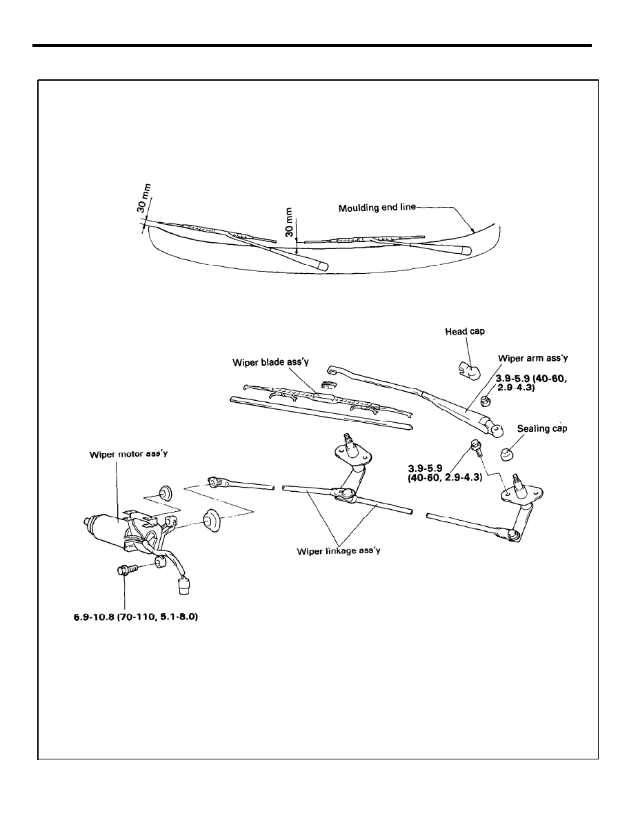
WINDSHIELD WIPER AND WASHER
FRONT WIPER
COMPONENTS
TORQUE : Nm (kg.cm, Ib.ft)
9 0 - 5 6
WINDSHIELD WIPER AND WASHER
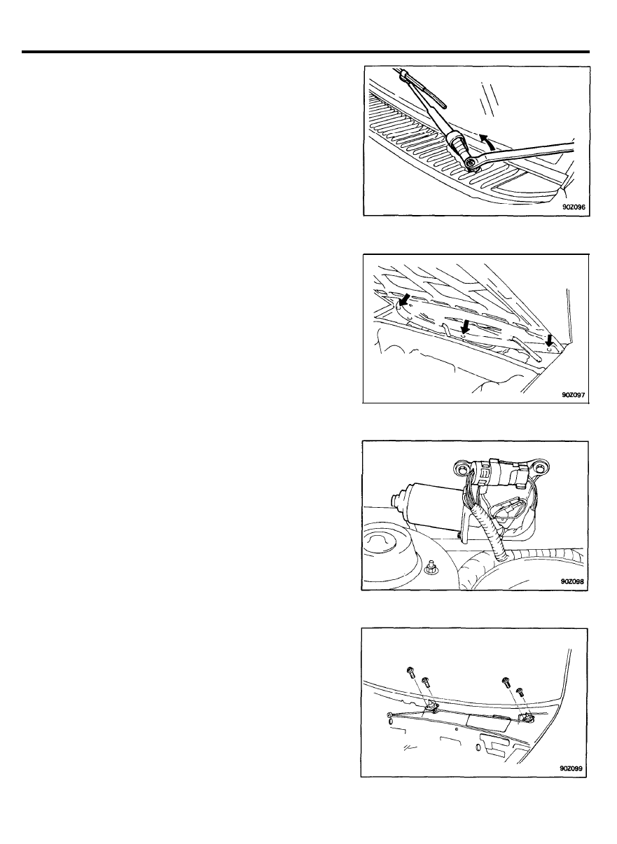
R E M O V A L A N D I N S T A L L A T I O N O F
FRONT WIPER
Removal
1. With opening the wiper arm head cap, remove the nut.
NOTE
Care must be taken not to scratch in the engine hood.
2. Remove wiper arm and blade assembly.
3. Remove the cowl top sealing cap.
4. Remove the cowl top cover.
5. Remove the wiper motor connector.
6. Remove the wiper motor mounting bolt.
7.
Disconnect the motor from the link, then remove the motor
assembly.
NOTE
When removing the wiper motor only, it can be done by
steps 5 to 7.
8. Remove the wiper link mounting bolt.
9.
Take out the wiper link assembly from the cowl top panel.
9 0 - 5 7
WINDSHIELD WIPER AND WASHER
Installation
1. Install the windshield wiper link assembly.
2.
Connect the wiper motor to the link securely, then install the
motor assembly.
3. Install the cowl top cover.
4. Install the cowl top sealing cap to the drive shaft.
5.
Connect the wiper arm and blade assembly to the wiper pivot
housing.
6.
Position the wiper arm and blade assembly at the distance
of 30 mm from the windshield glass moulding endline.
7. Tighten the wiper arm and blade mounting nut.
9 0 - 5 8
WINDSHIELD WIPER AND WASHER
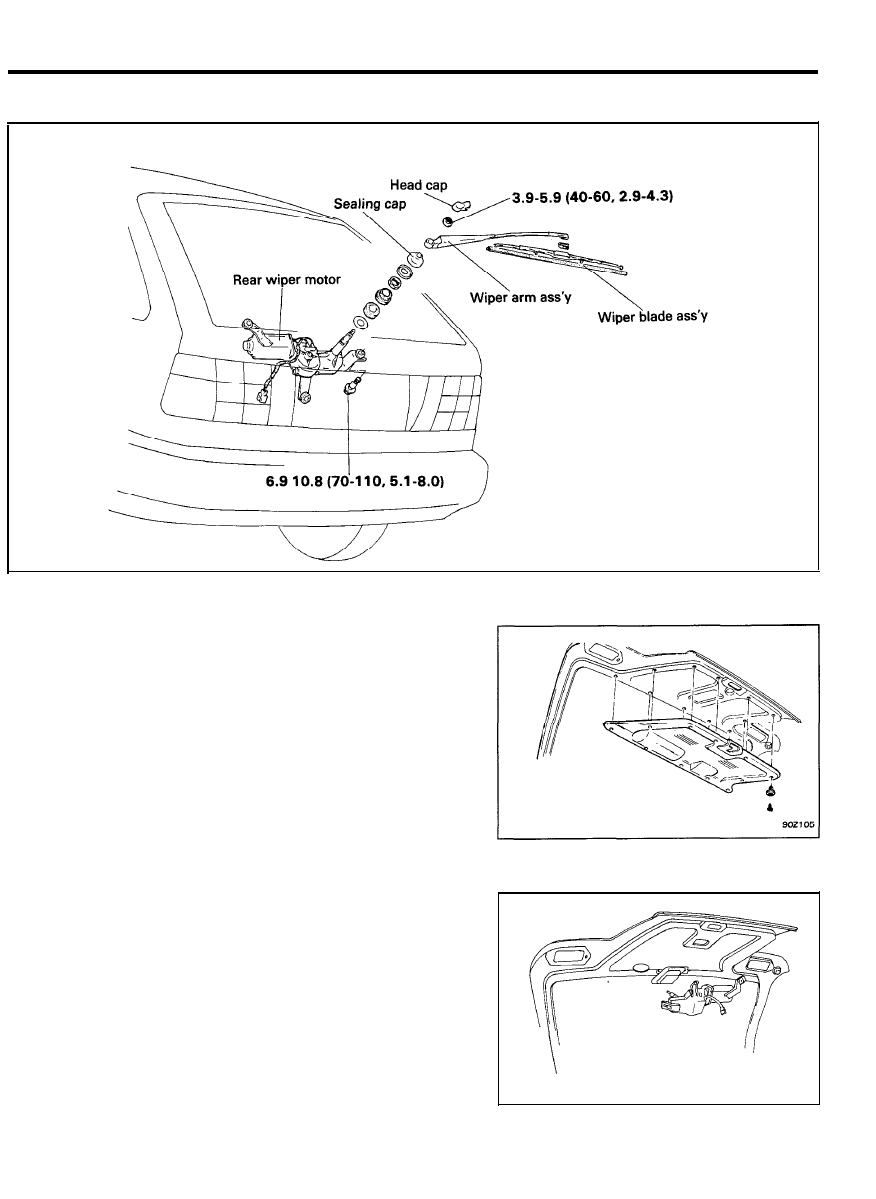
REAR WIPER
COMPONENTS
R E M O V A L A N D I N S T A L L A T I O N O F R E A R
WIPER
Removal
1. Remove the rear wiper arm assembly.
2. Remove the tailgate trim.
3. Remove the rear wiper motor from the tailgate.
9 0 - 5 9
WINDSHIELD WIPER AND WASHER
INSPECTION
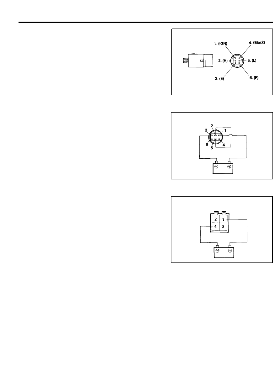
FRONT WIPER MOTOR
Speed operation check
1. Remove the connector from front wiper motor.
2. Attach the positive (+) lead from the battery to terminal 1
and the negative (-) lead to terminal 5.
3. Check that the motor operates at low speed.
4.
Connect the positive (+) lead from the battery to terminal 1
and the negative (-) lead to terminal 2.
5. Check that the motor operates at high speed.
Automatic stop operation check
Motor side
1. Operate the motor at low speed.
2.
Stop motor operation anywhere except at the off position by
disconnecting terminal 5.
3. Connect terminals 5 and 6.
4.
Connect the positive (+) lead from the battery to terminal 1.
5.
Check that the motor stops running at the off position after
the motor operates again.
REAR WIPER MOTOR
Speed operation check
1. Remove the connector from the rear wiper motor.
2. Attach the positive (+) lead from the battery to terminal 1
and the negative (-) lead to terminal 4.
3. Check that the motor operates.
Motor side
9 0 - 6 0
WINDSHIELD WIPER AND WASHER
W I N D S H I E L D W A S H E R
S P E C I F I C A T I O N S
Items
Washer motor
Motor type
Pump type
Rated voltage
Current
Discharge pressure
Flow rate
Over load capacity (continuous operation)
With water
Racing
Specifications
DC ferrate magnet type (M.P.I.)
DC solenoid type (F.B.C.)
Centrifugal type
DC. 12V
MAX. 3.8A (MPI)
MAX. 3.5A (FBC)
MIN. 1.2 kg/cm
2
MIN. 1,320 cc/min.
MAX. 60 sec.
MAX. 20 sec.
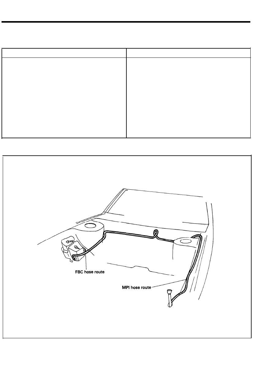
C O M P O N E N T S ( F R O N T W A S H E R )
9 0 - 6 1
WINDSHIELD WIPER AND WASHER
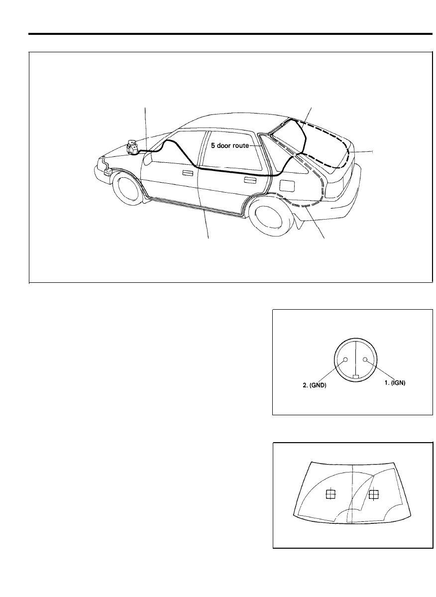
COMPONENTS (REAR WASHER)
FBC hose route
5 door route
3 door route
MPI hose route
3 door route
INSPECTION
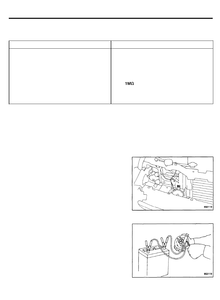
WASHER MOTOR
1.
With the washer motor installed to the washer tank, fill the
washer tank with washer fluid.
2. Attach the positive (+) lead from the battery to terminal 2,
and negative (-) lead to the ground.
3. Check that the washer motor runs and washer fluid is
ejected.
S E R V I C E A D J U S T M E N T P R O C E D U R E S
1. Check the washer fluid contact point.
2.
Adjust the washer fluid contact point by using a metal wire
to move the washer nozzle ball.
3.
If the amount of washer fluid ejected is too small, check for
clogged, bent or crushed washer piping. Check the clipped
points too, because the tube might be crushed.
(COMPONENT SIDE)
9 0 - 6 2
CLOCK
CLOCK
SPECIFICATIONS
Items
Specifications
Rated voltage
Operating voltage range
Operating temperature range
Current consumption (with DC. 13V)
DC. 12V
DC. 6 - 16V
- 3 0 ~ + 8 0 ° C ( - 2 2 - + 1 7 6 ° F )
MAX. 6 mA (with display)
MAX. 150 mA (with display illuminated)
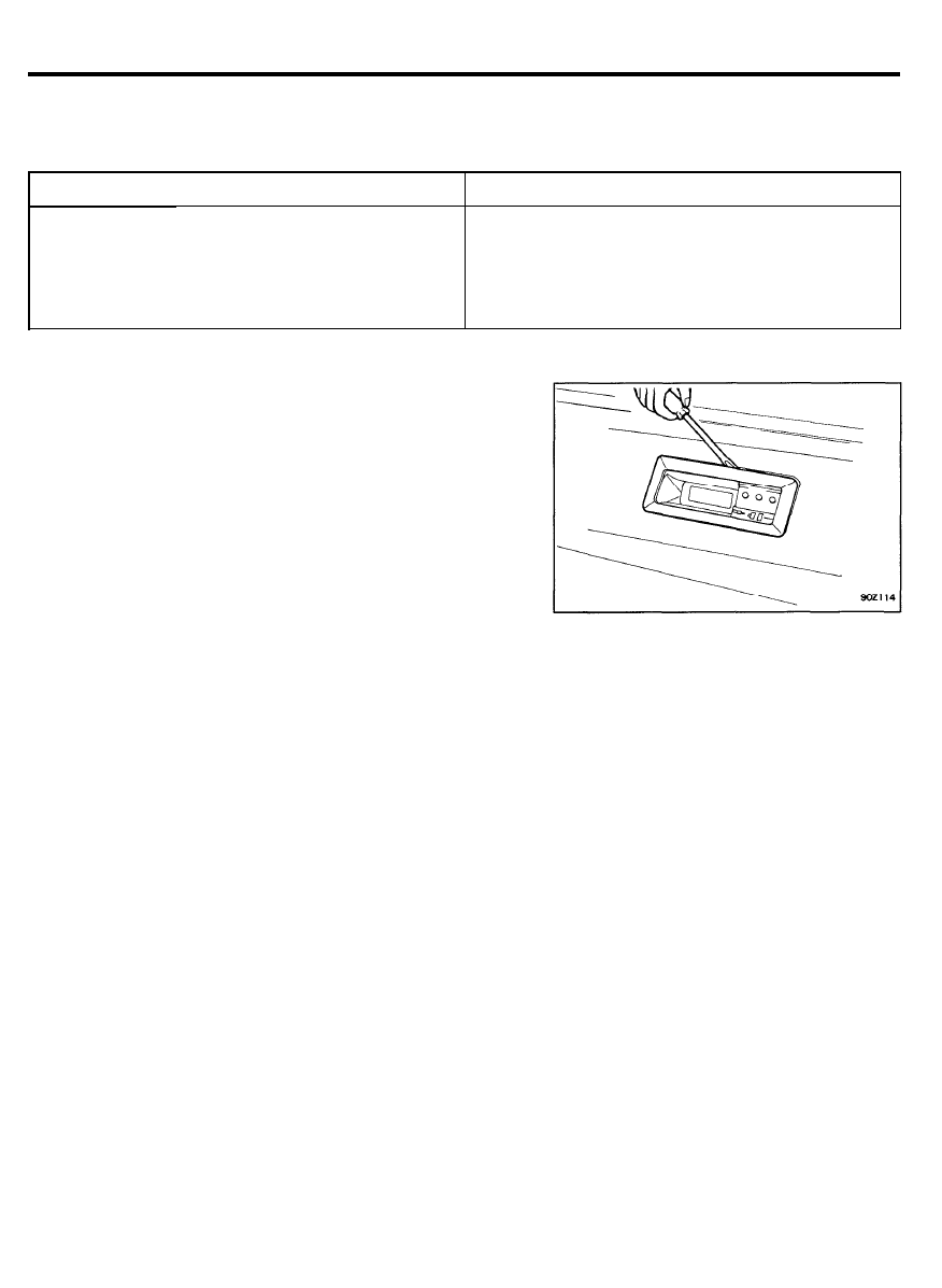
R E M O V A L
1. Remove the digital clock by using a flat type screwdriver.
2. Remove the wiring connector.
3. Remove the digital clock assembly
CAUTION
The clock is composed of delicate electronic components
containing a crystal oscillator, transistor, etc. and should
be handled with care. Specialized technical skill is needed
to repair the internal mechanism of this clock. Do not
attempt to disassemble it. If the clock itself is mal-
functioning, replace the entire assembly.
9 0 - 6 3

CIGARETTE LIGHTER
CIGARETTE LIGHTER
SPECIFICATIONS
Items
Specifications
Rated voltage
DC. 12V
Return time
13 ± 5 sec.
Insulation resistance
MIN.
(with 500V megger)
9 0 - 6 4
SUN ROOF
SUN ROOF
SPECIFICATIONS
Items
Sun roof motor
Rated voltage
Operating voltage
Testing voltage
No load rotation and electric current
Restriction torque and electric current
Clutch quality for output shaft
Early days torque
10,000 cycle test
Dissociation resistance
Sun roof switch
R a t e d v o l t a g e
Operating force
Max. load ampere
Operating temperature range
Insulated resistance
Specifications
DC 12 V
DC 9 ~ 15V
DC 13 ± 0.2V
MAX. 180 rpm, MAX. 6A
MIN. 50 kg.cm, MAX. 35A
30 ~ 40 kg.cm
25 ~ 50 kg.cm
MIN.
(with 500 megger)
DC 12V
0 . 5 ~ 1.0 kg
15A (Motor load)
- 4 0 ° C ~ + 8 0 ° C ( 4 0 ° F - + 1 7 6 ° F )
MIN.
(with 500V megger)
I N S P E C T I O N
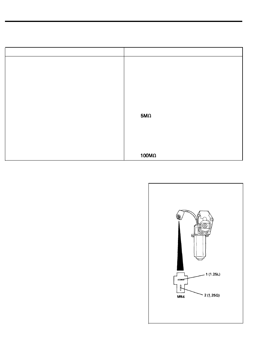
M O T O R
1. Remove the motor connector.
2. Attach the positive (+) lead from the battery to terminal 2
and negative (-) lead to terminal 1.
3. Check that the motor operates clockwise.
4. Attach the positive (+) lead from the battery to terminal 1
and negative (-) lead to terminal 2.
5. Check that the motor operates counter-clockwise.
9 0 - 6 5
SUN ROOF
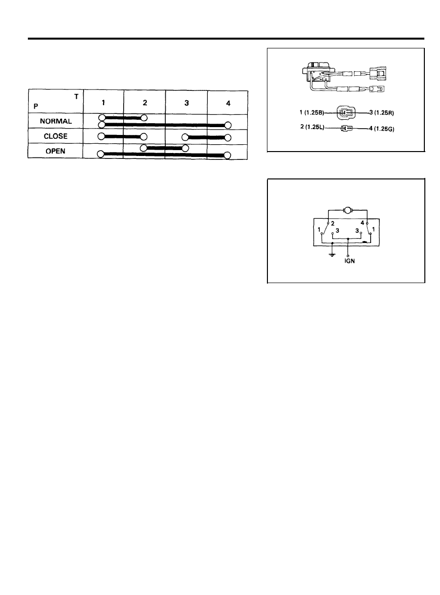
S W I T C H
Use an ohmmeter to check the continuity of the switch. If the
continuity is not as specified, replace the switch.
9 0 - 6 6
HORN
HORN
SPECIFICATIONS
Items
Type
Rated voltage
Power consumption
Sound level
Horn effective voltage
Operating temperature range
Insulation resistance
Fundamental frequency
Low pitch
High pitch
Specifications
Flat
DC. 12V
MAX. 3.5A (at DC 12V)
110 ± 5 dB (at DC 12V, 2m)
DC 10V ~ DC 14.5V
- 4 0 ° C ~ +80°C (-40°F - +176°F)
MIN.
(By 500V megger)
350 ± 20 Hz
415 ± 20 Hz
R E M O V A L
1. Disconnect the negative cable of battery.
2. Remove the radiator grille and head lamp.
3. Remove the horn attaching bolt. (on the radiator support
panel).
4. Remove the horn connector.
5. Remove the horn.
NOTE
Check horn adjusting screw for looseness.
A D J U S T M E N T
Operate the horn, and adjust the tone to a suitable level. (by
turning the adjusting screw to the right “down” or the left “up”)
CAUTION
After adjusting, apply a small amount paint around the screw
to prevent the adjusting screw from becoming loose.
9 0 - 6 7
TIME AND ALARM CONTROL UNIT
TIME AND ALARM CONTROL UNIT (T.A.C.U.)
SPECIFICATIONS
Items
Rated voltage
Operating voltage range
Operating temperature range
Insulation resistance
Rated load
Variable intermittent wiper
Rear defogger (heated) timer
Seat belt warning
Door warning
Specifications
DC. 12V
DC. 9 ~ 16V
-30°
~
+80°C (-22°F
~
+176°F)
MIN. 100
(with 500V megger)
MAX. 5A (Inductance load)
DC. 14.3V, 200W (Resistance load)
DC. 12V, 1.2W (Lamp load)
DC. 13.5V, 350mA (Inductance load)
DC. 13.5V, 350mA (Inductance load)
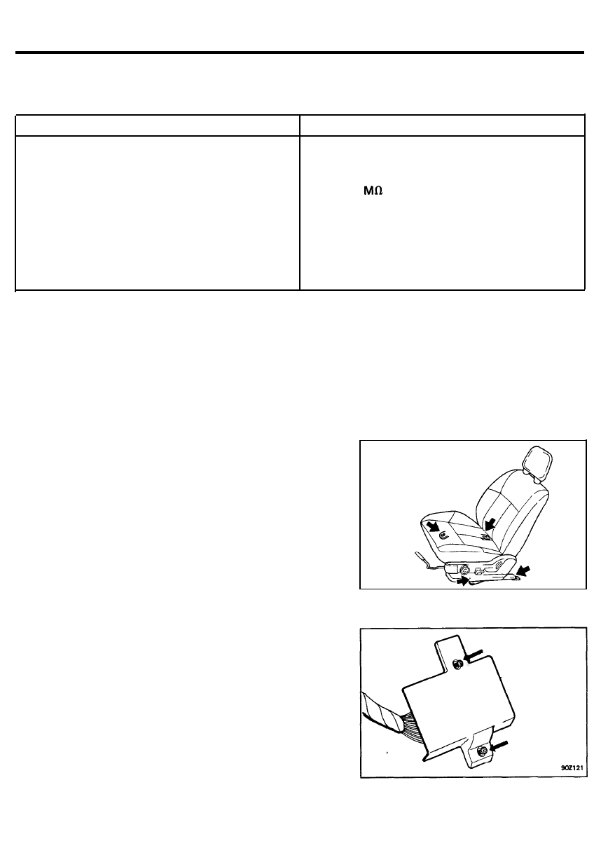
REMOVAL
1. Remove the front LH seat. (4 bolts)
2. Remove the T.A.C.U. cover. (2 tapping screws)
3. Remove the T.A.C.U. from the floor. (2 bolts)
4. Remove the connector.
9 0 - 6 8
TIME AND ALARM CONTROL UNIT
I N S P E C T I O N
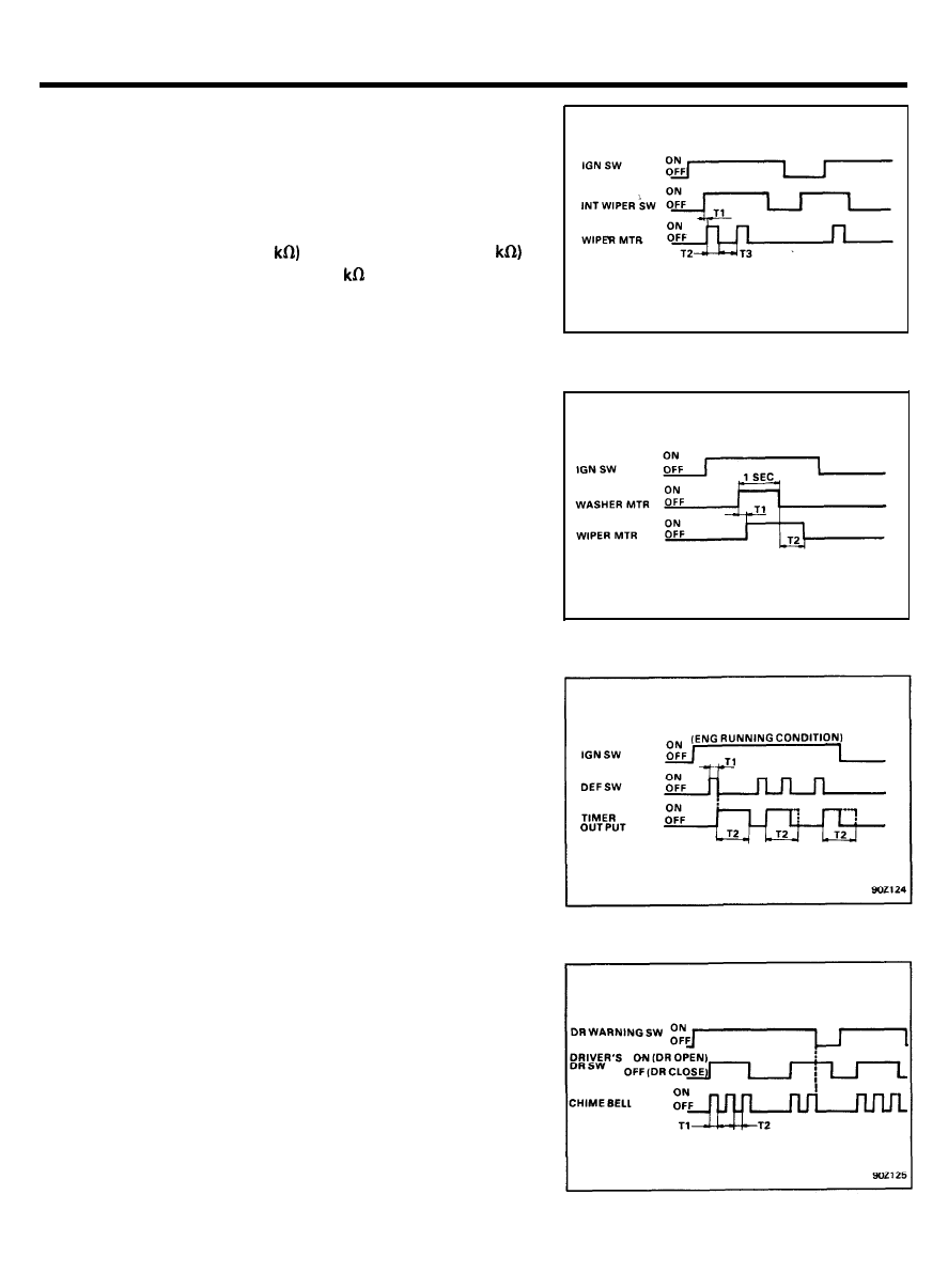
VARIABLE INTERMITTENT WIPER
1. Operating characteristic : Fig.1
2. T
1
: MAX. 0.5 sec.
T
2
: Time of wiper motor 1 rotation.
T
3
: 1.5 ± 0.7 sec. (VR=0
~ 10.5 ± 3 sec. (VR=50
3. Variable resistance (VR) : 50 ± 10
4. Relay operating sound : MAX. 50 dB/20 cm
W A S H E R
1. Operating characteristic : Fig.2
2. T
1
: 0.4 - 1.2 sec.
T
2
: 2.0 - 4.7 sec.
3.
This function should be operated preferentially even though
the variable intermittent wiper is operating.
REAR DEFOGGER (HEATED) TIMER
1. Operating characteristic : Fig.3
2. T
1
: MAX. 0.5 sec.
T
2
: 10 ± 3 min.
DOOR WARNING
1. Operating characteristic : Fig.4
2. T
1
, T
2
: 0.3 ± 0.1 sec.
9 0 - 6 9
TIME AND ALARM CONTROL UNIT
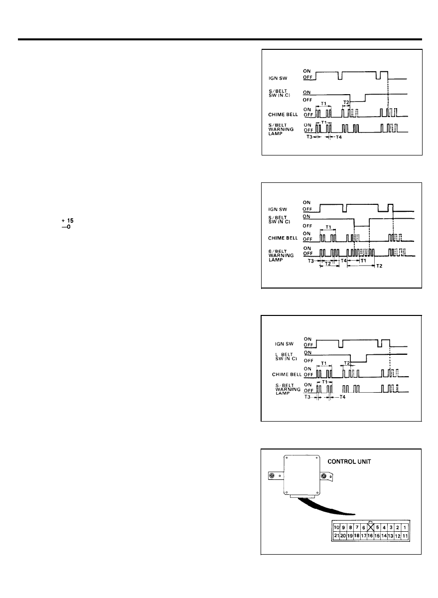
SEAT BELT WARNING
1.
Operating characteristic : Fig.5
2.
T
1
: 6 ± 1 sec.
T
2
: MAX. 6 ± 1 sec.
T
3
, T
4
: 0.3 ± 0.1 sec.
PASSIVE SEAT BELT WARNING
1.
Operating characteristic : Fig. 6
2.
T
1
: 6 ± 1 sec.
T
2
: 60
sec.
T
3
, T
4
: 0.3 ± 0.1 sec.
LAP BELT WARNING
1. Operating characteristic : Fig. 7
2. T
1
: 6 ± 1 sec.
T
2
: MAX. 6 ± 1 sec.
T
3
, T
4
: 0.3 ± 0.1 sec.
3.
It should be operated by the passive seat belt warning when
both of passive seat belt warning and lap belt warning are
operating simultaneously.
CONTROL UNIT
1. After tracing the problem to the control unit, replace it with
a new one. Check for proper operation.
2.
If system operates properly, the original control unit is faulty.
9 0 - 7 0
TIME AND ALARM CONTROL UNIT
REAR HEATED (DEFOGGER) GLASS
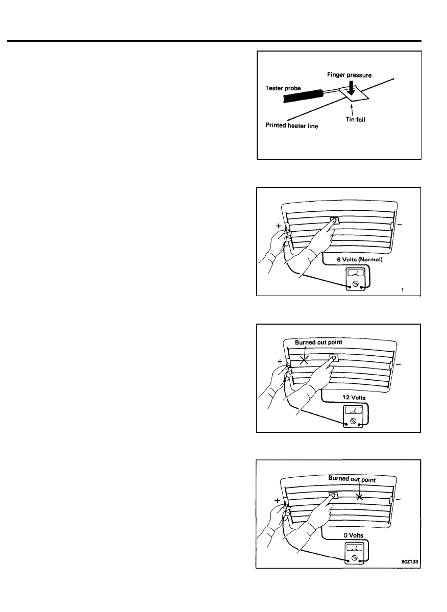
PRINTED HEATER LINE CHECK
CAUTION
Wrap tin foil around the end of the voltmeter test lead to
prevent damaging the heater line. Apply finger pressure on the
tin foil, moving the tin foil along the grid line to check for open
circuits.
1.
Turn on the defogger switch and use a voltmeter to measure
the voltage of each heater line at the glass center point. If
a voltage of approximately 6V is indicated by the voltmeter,
the heater line of the rear window is considered satisfactory.
2.
If a heater line is burned out between the center point and
(+) terminal, voltmeter indicates 12 volts.
3.
If a heater line is burned out between the center point and
(-) terminal, the voltmeter indicates 0 volts.
9 0 - 7 1
TIME AND ALARM CONTROL UNIT
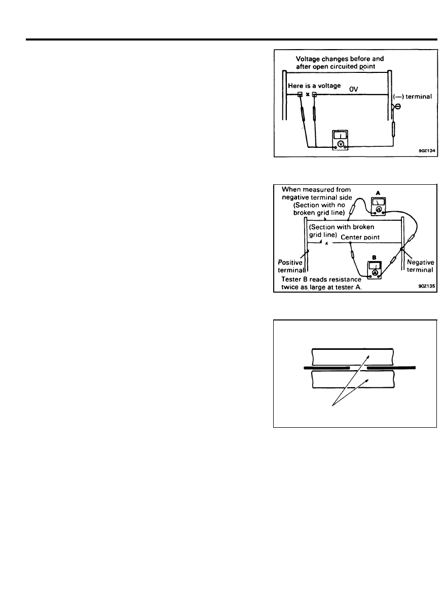
4.
To check for open circuits, slowly move the test lead in the
direction that the open circuit seems to exist. Try to find a
point where a voltage is generated or changes to 0V. The
point where the voltage has changed is the open-circuited
point.
Defogger OFF
5.
Use an ohmmeter to measure the resistance of each heater
line between a terminal and the center of a grid line and
between the same terminal and the center of one adjacent
heater line after another. The section involving a broken
heater line indicates resistance twice as that in other section.
In the affected section, move the test lead to a position
where resistance sharply changes.
Repair
Provide the following items:
1. Conductive paint
2 . P a i n t t h i n n e r
3. Masking tape
4. Silicone remover
5. Thin brush
Wipe the glass adjacent to the broken heater line, clean with
silicone remover and attach the masking tape as shown.
Shake the conductive paint container well, and apply three
coats with a brush at intervals of about 15 minutes apart.
Remove the tape and allow sufficient time for drying before
applying power.
For a better finish, scrape away excess deposits with a knife
after completely dried. (allow 24 hours)
Masking tape
CAUTION
After repairing, clean the glass with a soft dry cloth or
wipe along the grid line with a slightly moistened cloth.
9 0 - 7 2
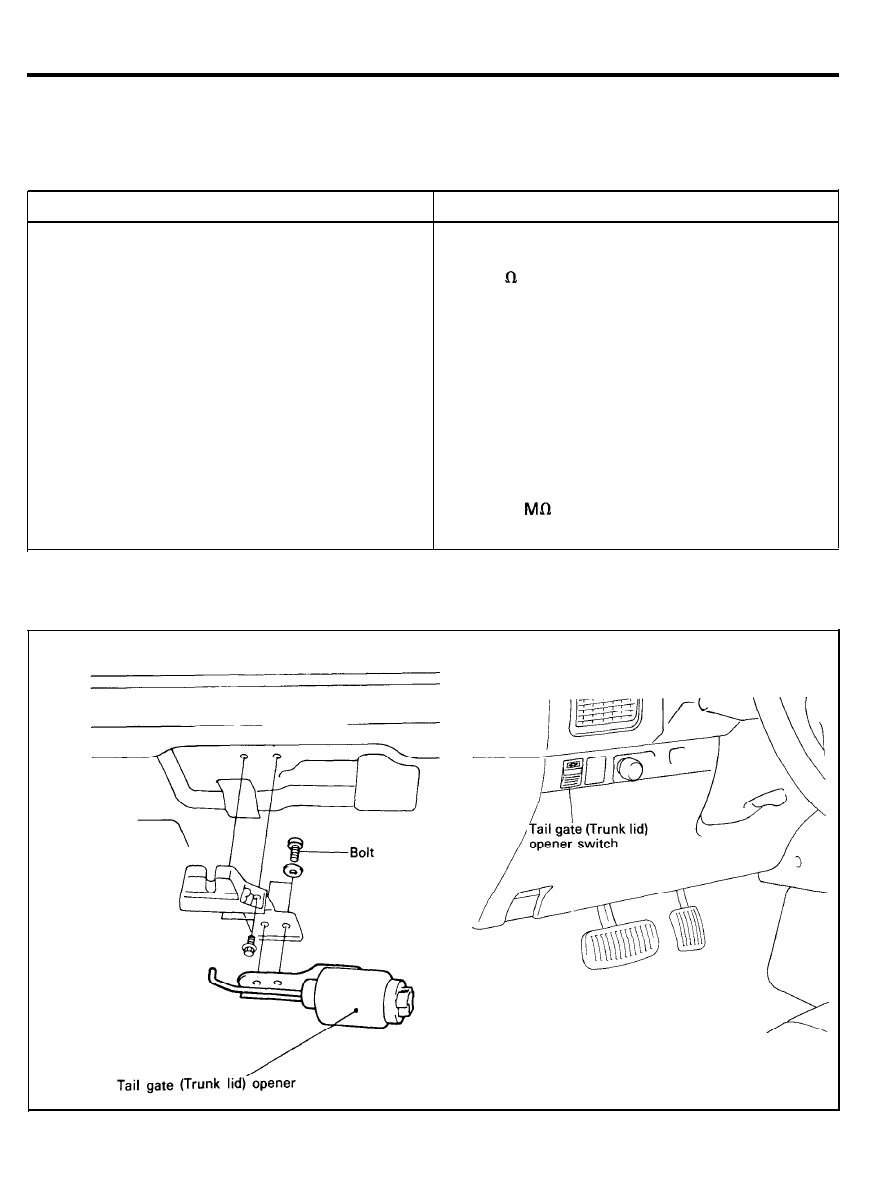
TAIL GATE OPENER (TRUNK LID OPENER)
T A I L G A T E O P E N E R ( 3 / 5 D O O R )
TRUNK LID OPENER (4 DOOR)
SPECIFICATIONS
Items
Tail gate opener (trunk lid opener)
Rated voltage
Insulating resistance
Operating temperature range
Rated current
Initial pulling torque
Circuit braker (at 7.5A)
Trip time
Recovery time
Tail gate opener switch (trunk lid opener switch)
Type
Rated voltage
Insulating resistance
Operating force
Specifications
DC 12V
MIN. 1 (with .500V megger)
4 0 ° C ~ + 8 0 ° C ( 4 0 ° F - + 1 7 6 ° F )
MAX. 16A
MIN. 3.6 kg (at DC 9V)
MIN. 5 kg (at DC 13V)
4
- 9 sec.
MAX. 5 sec.
Auto return type
DC 12V
MIN. 100
(with 500V megger)
0 . 4 - 1.0 kg
C O M P O N E N T S
9 0 - 7 3
TAIL GATE OPENER (TRUNK LID OPENER)
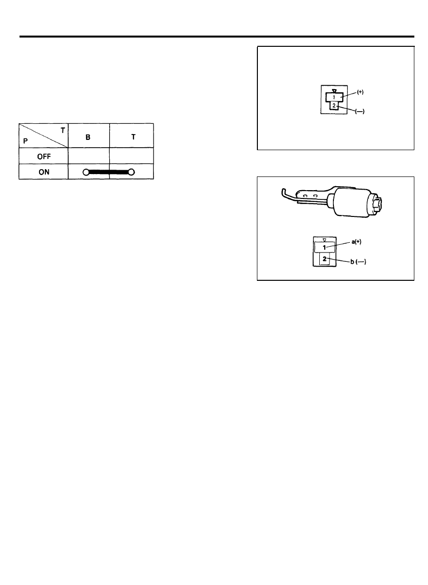
INSPECTION
TAILGATE OPENER SWITCH
(TRUNK LID OPENER SWITCH)
Remove the tail gate (trunk lid) opener switch and check
continuity between the terminals. If the continuity is not as
specified, replace the switch.
TAIL GATE OPENER
(TRUNK LID OPENER)
Remove the tail gate (trunk lid) opener and check continuity
between the terminal “a” and “b”. If there is no continuity,
replace the opener assembly.
9 0 - 7 4

AUTOMATIC TRANSAXLE AND KEY LOCK CONTROL SYSTEM
A U T O M A T I C T R A N S A X L E A N D K E Y L O C K C O N T R O L S Y S T E M
SPECIFICATION
Items
Control unit
Rated voltage
Operating voltage range
Operating temperature range
Rated load
A/T solenoid
Rated voltage
Rated current
Operating voltage range
Operating temperature range
Operating force
Initial pull in force
Spring force
Holding force
Key lock solenoid
Operating voltage range
Operating temperature range
Exciting current
Operating force
Pull in force
Holding force
Parking position switch
Rated load
Operating force
Operating temperature range
Specifications
DC 12V
DC 9 ~ 16V
-30°C ~ +80°C (-22°F - +176°F)
MAX. 1A (A/T solenoid)
MAX. 0.8A (Key lock solenoid)
DC 12V
1A (MAX. 2A)
DC 9 ~ 16V
-30°C ~ +80°C (-22°F - +176°F)
0.4 kg.cm (at 12V, 20°C)
0.2 kg.cm (at 12V, 20°C)
1.5 kg.cm (at 12V, 20°C)
DC 9 ~ 16V
-30°C ~ +80°C (-22°F - +176°F)
MAX. 0.9A
MIN. 0.17 kg.cm (at DC 7.5 ± 0.1V)
MIN. 0.25 kg.cm (at DC 6 ± 0.1V)
1A (resistance load, at DC 12V)
0.8 ± 0.2 kgf
-30°C ~ +80°C (-22°F ~ +176°F)
9 0 - 7 5
AUTOMATIC TRANSAXLE AND KEY LOCK CONTROL SYSTEM
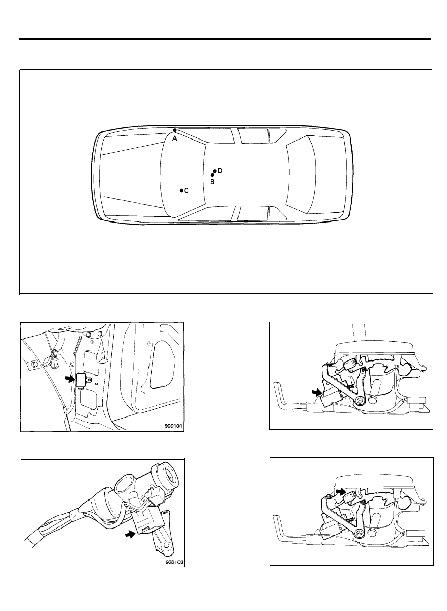
C O M P O N E N T S L A Y O U T
A. Cowl side panel
B. Shift lever assembly
C. Ignition key
D. Shift lever assembly
A. Control unit
B. A/T solenoid
C. Key lock solenoid
D.
P/position switch
9 0 - 7 6
AUTOMATIC TRANSAXLE AND KEY LOCK CONTROL SYSTEM
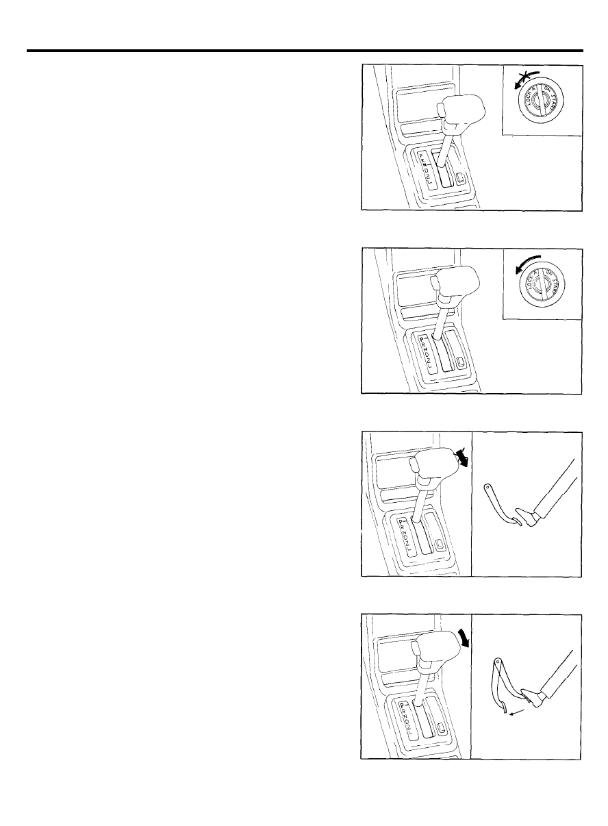
S Y S T E M C H E C K
KEY LOCK SYSTEM
1.
Check that the ignition key cannot be turned to “LOCK (OFF)”
position, when the position of the shift lever is not in “P”
position.
2. Check that the ignition key turns to the “LOCK (OFF)”
position, when the shift lever is set to the “P” position.
SHIFT LOCK SYSTEM
1. Check that under the following conditions, the shift lever
cannot be moved from the “P” position to any other position.
IGNITION KEY POSITION : “ON”
BRAKE PEDAL : NOT DEPRESSED
BUTTON : PRESSED
2.
Check that under the following conditions, the shift lever can
be moved from the “P” position to other position.
IGNITION KEY POSITION : “ON”
BRAKE PEDAL : DEPRESSED
BUTTON : PRESSED
9 0 - 7 7
AUTOMATIC TRANSAXLE AND KEY LOCK CONTROL SYSTEM
INSPECTION
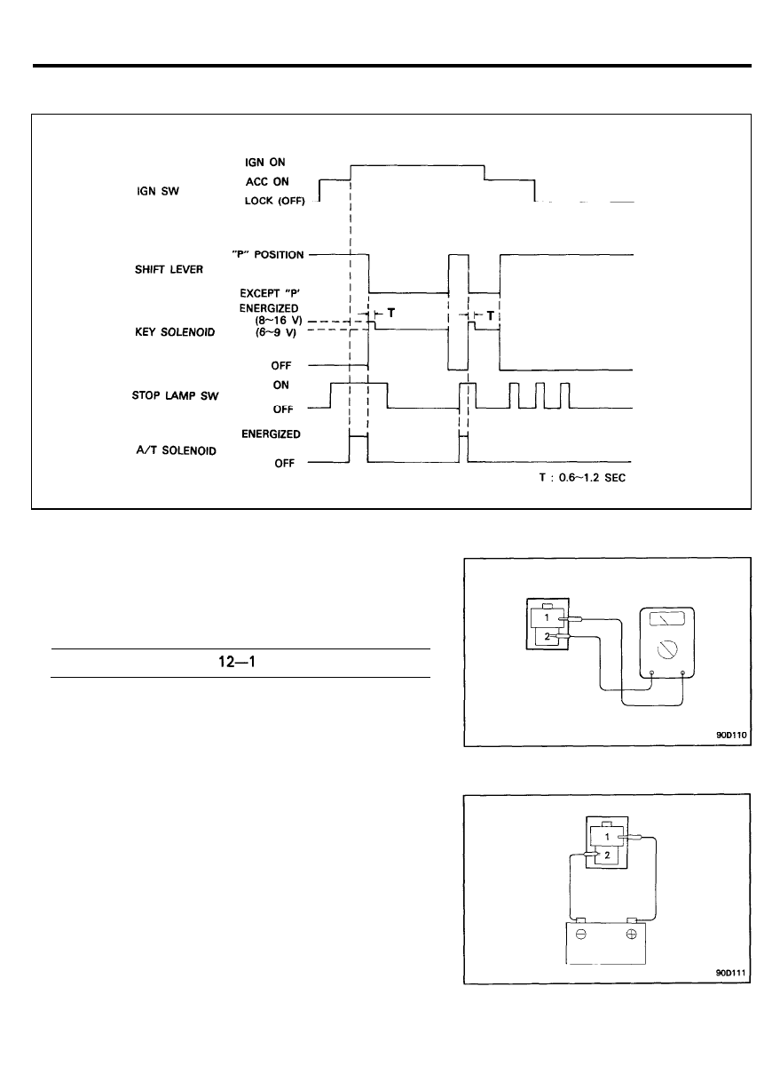
TIMING CHART
A U T O M A T I C T R A N S A X L E S O L E N O I D
1. Remove the solenoid connector.
2. Using an ohmmeter, measure the resistance between
terminals.
Standard resistance :
3. Attach the positive (+) lead from the battery to terminal 1.
and the negative (-) lead to terminal 2.
4. Check that an operation noise can be heard from the
solenoid.
9 0 - 7 8
AUTOMATIC TRANSAXLE AND KEY LOCK CONTROL SYSTEM
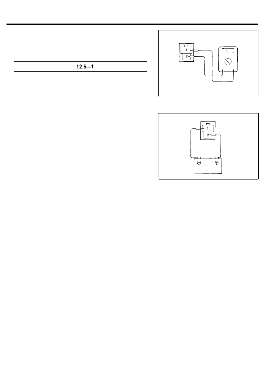
KEY LOCK SOLENOID
1. Remove the solenoid connector.
2. Using an ohmmeter, measure the resistance between
terminals.
S t a n d a r d r e s i s t a n c e :
3. Attach the positive (+) lead from the battery to terminal 2.
and the negative (-) lead to terminal 1.
4. Check that an operating noise can be heard from the
solenoid.
9 0 - 7 9
Wyszukiwarka
Podobne podstrony:
08 Body electrical system(BE)
Electronics 4 Systems and procedures S
7 Electrical System
0632 body to body blue system VQBXU2OV2SYZQLWIQO7NQU5JZS2IV434XDA5DFI
Body- building systemTrening obwodowy (forma obwodowa kształtowania siły)., BILOGIA, FIZJOLOGIA CZŁO
How an inverter fits into your solar electric system By Jo
FE 05 21 body 120710
02 engine electrical system
M39a Body Wiring System
21 sciany szczelinowe z systemem polaczen sekcji cws na planie kola(1)
Electrical systems
Body Electrical
21 12 pjęcia i systemy pedagogiczne
21 Technologie mikroelektroniczne systematyka
Electronics 4 Systems and procedures S
7 Electrical System
02 E63 64 Body Electrical
04a E65 Central Body Electronics
więcej podobnych podstron