
Initial Print Date: 02/04
Table of Contents
Subject
Page
Voltage Supply and Bus System . . . . . . . . . . . . . . . . . . . . . . . . . . . . . . . .4
Changes Compared to the E60 . . . . . . . . . . . . . . . . . . . . . . . . . . . . . . . .4
Bus System Changes . . . . . . . . . . . . . . . . . . . . . . . . . . . . . . . . . . . . . . . .5
General Vehicle Electrical System . . . . . . . . . . . . . . . . . . . . . . . . . . . . . .6
Changes Compared to the E60 . . . . . . . . . . . . . . . . . . . . . . . . . . . . . . . .6
Changes Compared to the E60 . . . . . . . . . . . . . . . . . . . . . . . . . . . . . . . .6
System Components . . . . . . . . . . . . . . . . . . . . . . . . . . . . . . . . . . . . . . . . .6
Control Unit MDS . . . . . . . . . . . . . . . . . . . . . . . . . . . . . . . . . . . . . . . . . . . .7
Control Button . . . . . . . . . . . . . . . . . . . . . . . . . . . . . . . . . . . . . . . . . . . . . . .7
Glass Tilt Sunroof . . . . . . . . . . . . . . . . . . . . . . . . . . . . . . . . . . . . . . . . . . . .7
Sunroof Visor . . . . . . . . . . . . . . . . . . . . . . . . . . . . . . . . . . . . . . . . . . . . . . . .8
Changes Compared to the E60 . . . . . . . . . . . . . . . . . . . . . . . . . . . . . . . . . .9
Brake Force Display . . . . . . . . . . . . . . . . . . . . . . . . . . . . . . . . . . . . . . . . . . .10
E63 Advanced Safety Electronics . . . . . . . . . . . . . . . . . . . . . . . . . . . . .12
B-Pillar Satellites . . . . . . . . . . . . . . . . . . . . . . . . . . . . . . . . . . . . . . . . . . . . . .12
AITS I (Head Airbag) . . . . . . . . . . . . . . . . . . . . . . . . . . . . . . . . . . . . . . . . . . .12
Active Knee Protection . . . . . . . . . . . . . . . . . . . . . . . . . . . . . . . . . . . . . . . . .13
E63/64 Body Electrical
Revision Date:

Subject
Page
E64 Advance Safety Electronics . . . . . . . . . . . . . . . . . . . . . . . . . . . . . .15
Function Mode . . . . . . . . . . . . . . . . . . . . . . . . . . . . . . . . . . . . . . . . . . . . . . .16
SBSL . . . . . . . . . . . . . . . . . . . . . . . . . . . . . . . . . . . . . . . . . . . . . . . . . . . . . . . .16
SBSR . . . . . . . . . . . . . . . . . . . . . . . . . . . . . . . . . . . . . . . . . . . . . . . . . . . . . . .16
URSS Service Information . . . . . . . . . . . . . . . . . . . . . . . . . . . . . . . . . . . . . .18
Mechanical Deployment (For Service) . . . . . . . . . . . . . . . . . . . . . . . . . . . .18

3
E63/64 Body Electrical
Body Electrical
Model: E63/64
Production: Start of Production MY 2004
After completion of this module you will be able to:
• Understand the electrical changes in t he E63/64
• Explain the operation of the sunroof
• Relate ASE changes to E63/E64
• Recognize SGS seat in the E64
Voltage Supply and Bus System
The vehicle electrical system of the E63/64 is essentially based on the electrical system
of the E60. This documentation describes the differences in the power supply, bus sys-
tems and in the general vehicle electrical system compared to the E60.
In the E60/E63, an energy management function is responsible for the power require-
ments of the vehicle both while driving as well as when stationary.
The most important integral parts of the energy management system are:
• Intelligent battery sensor IBS
• Power management software in the digital motor electronics DME or digital diesel
electronics DDE and in the IBS.
The power management controls the electric currents in the vehicle
• Terminal 30g relay actuated by the car access system
Power Supply
Changes Compared to the E60
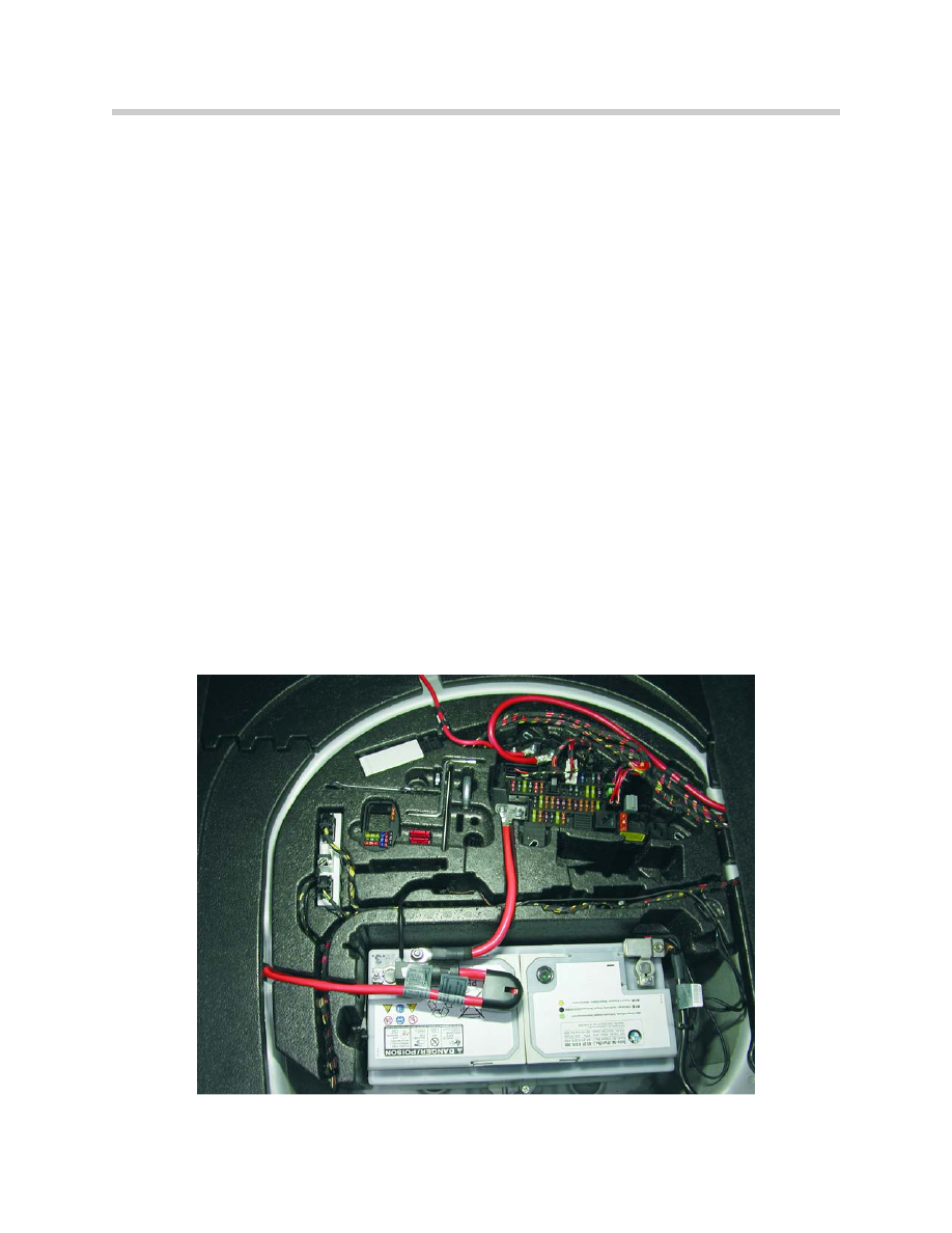
The battery is installed in the luggage compartment recess. The power distribution box in
the luggage compartment was repositioned from the side panel to the recess in the lug-
gage compartment. The vehicle electrical system is extended with the integrated power
supply module IVM if an 8-cylinder engine is installed.
4
E63/64 Body Electrical
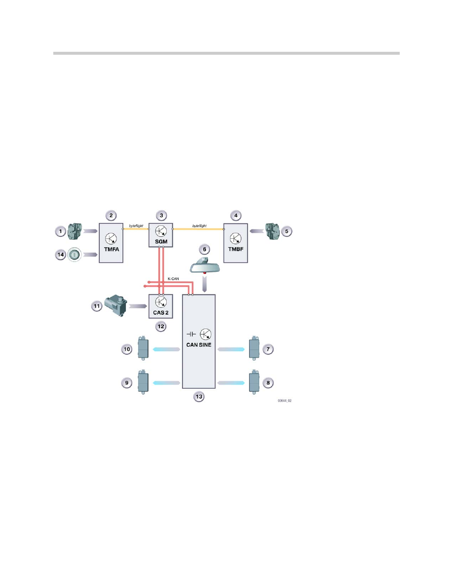
Bus System Changes
Instead of the control unit for the slide/tilt sunroof SHD the control unit for the glass roof
MDS is installed in the E63. There is no passenger's seat module SMBF in the E63.
5
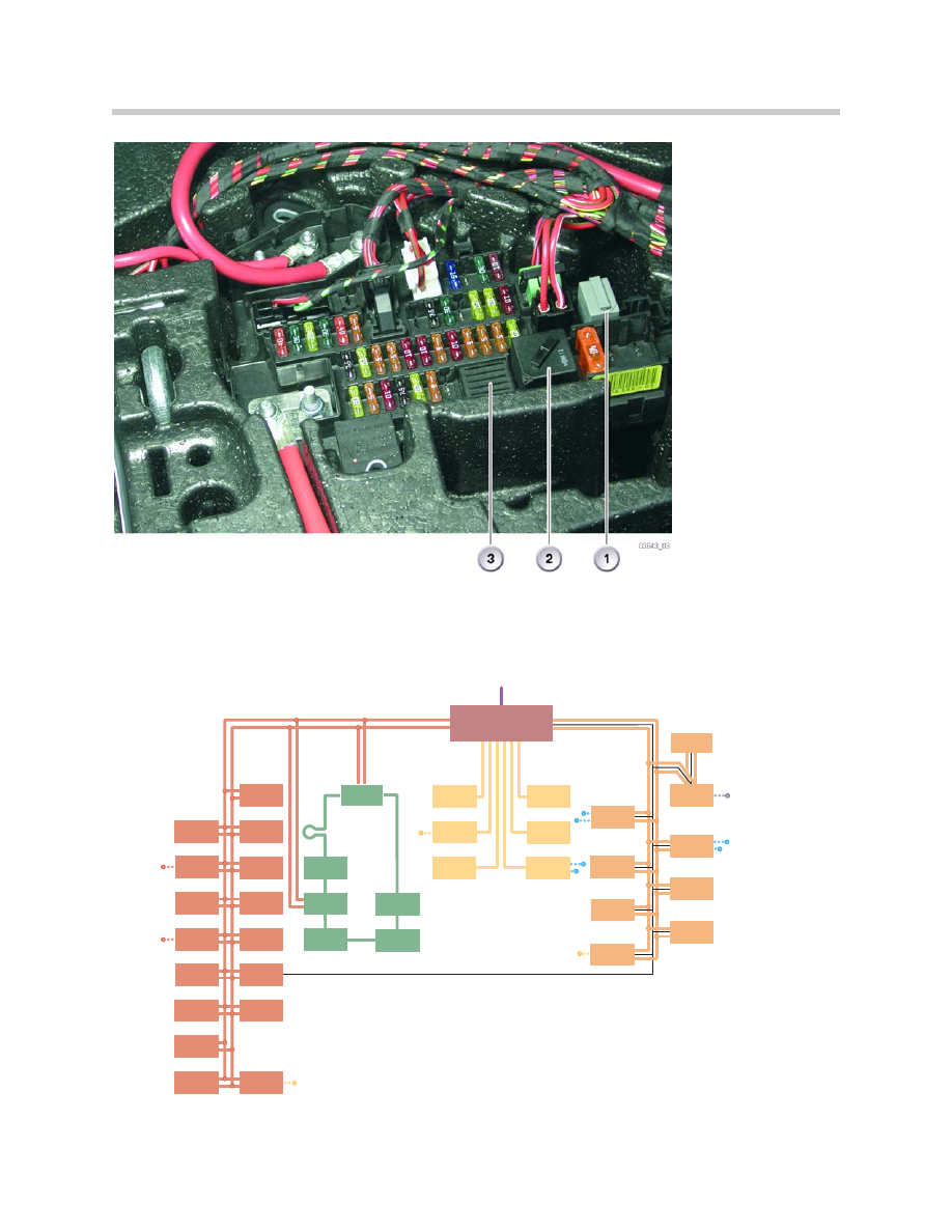
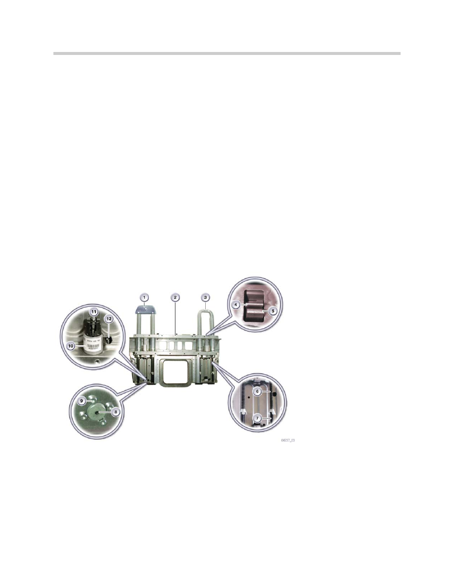
E63/64 Body Electrical
1. Rear window relay
2. Terminal 30g relay
3. Terminal 15 relay,
soldered
MPM
SH
SZM
MDS
PDC
CON
CAN-Sine
CAS2
RLS
KBM
AHM
SMFA
IHKA
LM
SBSL
SBSR
TMFA
TMBF
SFZ
SZL
KOMBI
CID
CCC
CDC
HUD
VM
TEL
TOP-HIFI
AFS
ACC
DSC
EGS
AHL
EKP*
MOST
FS
PT-CAN
SGM
D-Bus
K-CAN
byteflight
ARS
SMG
DME
03694_03c
General Vehicle Electrical System
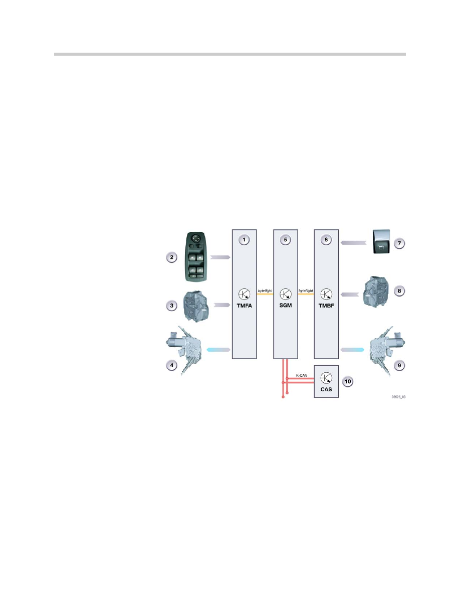
Power Windows
Changes Compared to the E60
The function of the power windows correspond to those of the E60. The rear
windows are fixed. The pins of the KBM for the rear windows are not used.
The following components are not installed in the E63:
• Switches, rear driver's door, rear passenger's door
• Power window motors with incremental sensor, rear driver's and
passenger's side
E63 Glass Tilt Sunroof
Changes Compared to the E60
Instead of the slide/tilt sunroof, the E63 features a glass tilt sunroof. The sunroof visor
is two-piece. Two motors are installed for operating the glass tilt sunroof.
System Components
The following components relating to the glass tilt sunroof are fitted in the vehicle:
• Control button for glass tilt sunroof
• Control unit, multi-drive sunroof MDS, for glass tilt sunroof
6
E63/64 Body Electrical
1. Driver's door module (TMFA)
2. Switch block on driver's door
3. Door contact, driver's door, front
4. Power window regulator, driver's
door, front
5. Safety and gateway module
(SGM)
6. Passenger's door module
(TMBF)
7. Power-window switch,
passenger, front
8. Door contact, passenger door,
front
9. Power window regulator
passenger door, front
10. Car access system (CAS)
11. Basic body module (KBM)
12. Power-window switch, driver,
rear
K-CAN
Bodyshell CAN
byteflight
byteflight
• Motor for glass tilt sunroof
• Motor for sunroof visor
Communication with other users in the vehicle, such as the car access system CAS takes
place via the K-CAN.
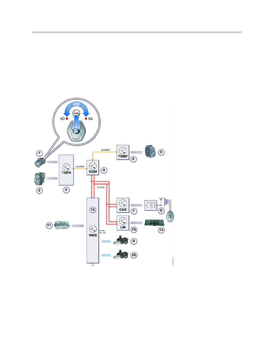
Control Unit MDS
The MDS is installed in the carrier in the glove compartment.
Functions
Control Button
The button functions are described in the Owner's Handbook.
Glass Tilt Sunroof
The functions of the glass tilt sunroof are based on the tilt functions of the E60 slide/tilt
sunroof.
7
E63/64 Body Electrical
1. Lock cylinder, driver's door
2. Door contact, driver's door
3. Driver's door module
(TMFA)
4. Safety and gateway module
(SGM)
5. Passenger door module
(TMBF) sunroof (MDS)
6. Door contact, passenger's
door
7. Car access system (CAS)
8. Remote control
9. Motor for glass tilt sunroof
10. Motor, sunroof visor
11. Glass roof control button
12. Control unit for glass tilt
(MDS)
13. Light module
14. Light module control switch

Sunroof Visor
The functions of the sunroof visor are based on the functions of the sunroof visor for the
panoramic glass sunroof.
Service Information
Initialization
Initialization of the glass tilt sunroof is based on that of the E60. The glass tilt sunroof can
be initialized either via the control button or the tester.
Only full initialization will ensure complete operability of the glass roof.
Manual Initialization with Control Button
The characteristic curve is relearned during every new or reinitialization of the glass tilt
sunroof.
Preconditions
The glass sunroof must be clean and be at room temperature. Terminal 15 ON must be
applied. When the glass tilt sunroof is subsequently initialized using the control button,
this button must remain pressed until the initialization procedure is concluded.
The control button is pressed and held in the lift sunroof direction. The initialization run
starts up approx.15 seconds after pressing the control button.
Glass Tilt Sunroof
The glass tilt sunroof can be replaced only together with the sunroof visor.
The motors and the control unit can be replaced individually. The glass tilt sunroof must
be encoded and initialized after replacing the control unit.
Alarm System
The alarm system detects and warns of any attempts to break in or tamper with the vehi-
cle. The system is installed in various types of vehicles in different country-specific ver-
sions.
The anti-theft alarm system, integrated in the CAN-Sine, communicates with the compo-
nents via the K-CAN or via the DWA bus. The DWA of the E63 is equipped with multiplex
microwave sensors, the CAN-Sine and the DWA LED.
For the first time at BMW, MuW (multiplex microwave sensors) sensors are fitted in
the E63.
8
E63/64 Body Electrical
The advantages of these MuW sensors are:
• Interior protection
• Effective MuW sensor detection during interior monitoring
• No false alarms triggered by MuW sensors during interior monitoring
The processor in the CAN-Sine features diagnostic capabilities and can be encoded.
The MuW sensors assume the secondary functions and the CAN-Sine the main control
unit function.
The E63 is not equipped with the Ultrasonic interior movement detector USIS. The DWA
logic and the emergency current siren with integrated tilt alarm sensor have been com-
bined to form one unit, i.e. the CAN-Sine.
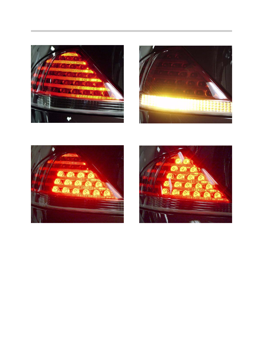
Exterior Lights
Changes Compared to the E60
The E63/64 features 2 lamp bulbs in each directional indicator for the front direction
indicator function.
The marker light of the E63 is fed from below into the light guide. The hotspot is located
at the feed point of the light guide.
The front side markers are equipped with lamp bulbs. LEDs are used for the tail
lights/brake lights.
9
E63/64 Body Electrical
1. Hall sensor, driver's door
2. Driver's door module (TMFA)
3. Safety and gateway module (SGM)
4. Passenger door module (TMBF)
5. Hall sensor, passenger's door
6. DWA LED
7. Multiplex microwave sensor,
passenger's door
8. Multiplex microwave sensor,
rear passenger's side door
9. Multiplex microwave sensor,
rear driver's side door
10. Multiplex microwave sensor,
driver's door
11. Bonnet contact
12. CAN-Sine tilt alarm sensor with
integrated emergency current siren
13. Car access system 2 (CAS 2)
14. Lock, driver's door
10
E63/64 Body Electrical
Brake Force Display
The BFD can currently be used only in the US country-specific version. The upper LEDs
of the rail light are used as the BFD as of a deceleration of 6 m/s2.

E63 Seats
The seats in the E63 have been adapted from the E46/2.
All seats feature a manual head restraint adjustment facility in up and down direction.
The sports seat additionally features a seat depth adjustment.
The seat functions have been adopted from the E46/2.
Steering Column Memory
The memory positions for the steering column are stored and managed in the center
console switch center.
Seat Heating
The seat heating is activated and controlled from the SZM. The seat heating is supplied
with a clocked voltage. The heating output control that is required in order to regulate the
temperature is achieved by pulse width modulation of the heating current. The clocking
frequency is 25 Hz.
11
E63/64 Body Electrical

E63 Advanced Safety Electronics
The advanced safety electronics ASE is the electronic safety system for the 6 Series
Coupe. In principle the ASE is the same as the system in the E60. The ASE has been
correspondingly adapted for the E63
The changes to the ASE system on the E63 have been made in the following areas:
• B-pillar satellites
• AITS I (head airbag)
• Active knee protector (US)
Note:
This Workshop Manual is only a supplement to the E60 Training Reference
manual. Only the changes compared to the E60 are described.
B-Pillar Satellites
The following changes have been made on the E63 to the B-pillar satellites:
• No ignition circuits for the active head restraints
• No ignition circuits for the rear side airbags
• No ignition circuits for the rear seat belt tensioners
The SBSL still controls and monitors the following trigger circuits:
• Head airbag (AITS I) left
• Seat belt tensioner, left
The SBSR still controls and monitors the following trigger circuits:
• Front airbag, passenger
• Head airbag (AITS I) right
• Seat belt tensioner, right
AITS I (Head Airbag)
The advanced inflatable tubular structure (AITS I) is used on the E63. The difference
compared to the AITS II of the E60 is the length adaptation to the body of the 6 Series
Coupe. The AITS I is the head airbag for the driver and passenger side. The AITS I
extends from the A-pillar back to the B-pillar and covers the entire side area of the
driver/passenger.
12
E63/64 Body Electrical
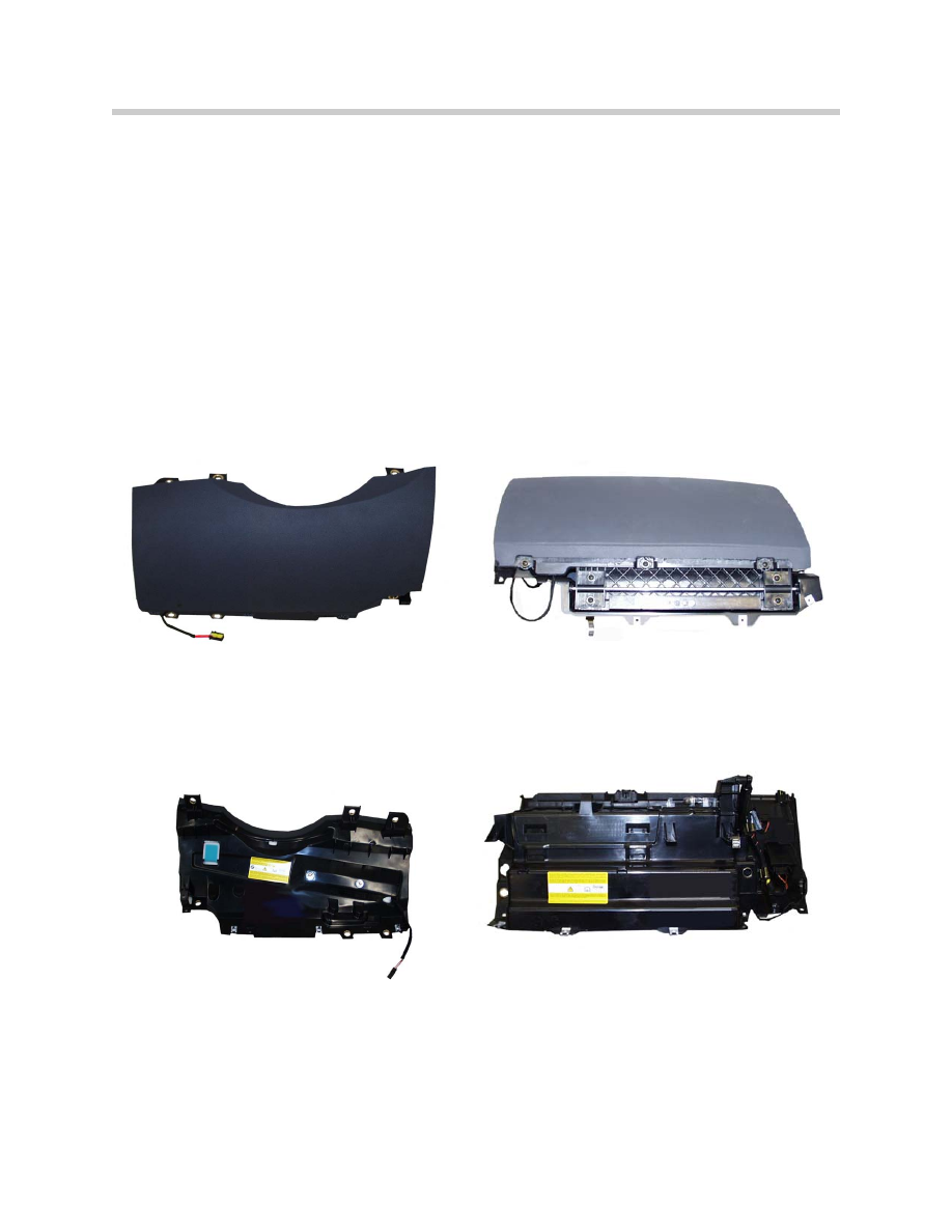
Active Knee Protection
The E63 US features knee airbags on the driver's side and passenger's side.
In the event of a crash, the knee airbag adds additional support for the knees. This initi-
ates a controlled forward shift of the upper body, which is cushioned by the relevant
airbag.
The knee airbag on the driver's side is located behind a cover under the steering column.
The knee airbag on the passenger's side is located behind a cover in the flap of the glove
compartment.
13
E63/64 Body Electrical
14
E63/64 Body Electrical
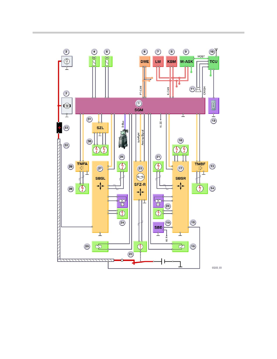
K-C
AN
PT
-C
AN
SGM
G
M
KBM
M-ASK
DME
TCU
CRASH
MOST
D-B
us
Kl. 30
TMFA
SZL
SBSL
TMBF
SBSR
SFZ
by
te
flight
SBE
Kl. R
S
O
S
LM
03261_03
2
1
28
30
29
20
21
19
22
25
16
14
27
18
24
15
26
17
13
31
3
4
11
5
7
8
9
10
6
12
23
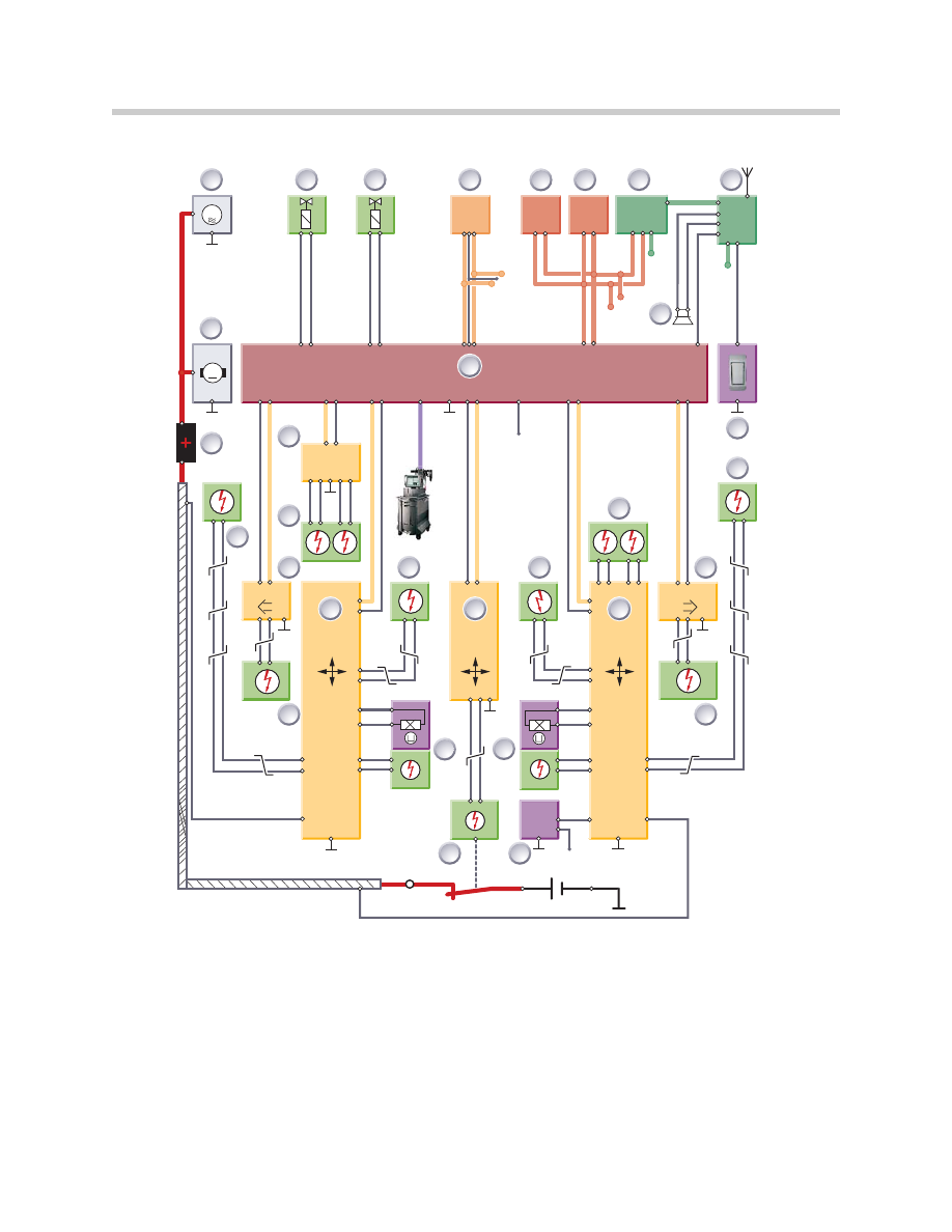
1. Starter
11. SGM
21. BST
2. Generator
12. Emergency Call Button
22. Seat Belt switch/tensioner, Driver
3. ECO valve (AFS Only)
13. Head Airbag AITS II, R/S
23. Vehicle Center Satellite
4. Servotronic Valve (optional)
14. Door Module Passenger Door
24. Knee Airbag, Driver
5. DME
15. Side Airbag, Passenger Door
25. B-Pillar Satellite L/S
6. Light Module
16. B-pillar satellite, R/S
26. Side Airbag Driver
7. KBM
17. Front Airbag, Passenger
27. Door Module Driver Door
8. MASK
18. Knee Airbag, Passenger
28. Head Airbag AITS II, L/S
9. TCU
19. Seat Belt switch/tensioner, Pass
29. Front Airbag, Driver
10. Emergency speaker
20. OC3
30. Steering column switch cluster
31. Main adapter point, eng. com.
E63 ASE Schematic

E64 Advance Safety Electronics
E64 Advance Safety Electronics are based on the systems of the E60/E63.
Changes to E64 ASE
The following charges have been made to the E64 ASE compared to the E60/E63:
• AITS head protection is eliminated
• New rollover protection system URSS added
• Seat-integrated belt system SGS
• New vehicle center satellite, SFZ-R, with Rollover and acceleration sensors
• Updated SGM to include actuators for Rollover protection system
Rollover Protection System
The Rollover protection system for the E64 consists of the following:
•
byteflight, the optical bus system
• SGM
• SBSL with acceleration sensors
• SBSR with acceleration sensors
• TMFA with door pressure sensor
• TMBF with door pressure sensor
• SFZ-R with Rollover sensor and Acceleration Sensors
• satellite switching center steering column SZL
• URSS unit
SFZ-R
The SFZ-R of the E64 includes the additional sensors for rollover protection system acti-
vation. Sensor data is sent via
byteflight to the SGM. The SFZ-R is mounted on the
transmission tunnel.
SFZ-R Sensors
Included in SFZ-R are the following sensors:
• Longitudinal acceleration sensor (x axis)
• Transverse acceleration sensor (y axis)
• Low g sensor (Rollover sensor) (Z-axis)
• Turning rate sensor (turn in the x axis)
15
E63/64 Body Electrical
Function Mode
The SFZ-R contains two processors, the main processor and the auxiliary processor. The
main processor computes an estimated angle of the vehicle based on data received from
the ASE system sensors and information from the Rollover sensor and the turning rate
sensor. The auxiliary processor computes estimated vehicle angle based on data
received for the transverse acceleration sensors, the Rollover sensor and the turning rate
sensor.
Information from both the main and auxiliary processors is constantly compared. If the
processors determine the angle of the vehicle exceeds a fixed threshold the following
sequence is initiated:
• The main processor advises the SGM the vehicle has exceeded threshold limits vi
the
byteflight
• The auxiliary processor activates the arming line (New to the E64) to the SGM
• The SGM evaluated information received from both processors
• The SGM activates both Rollover protection devices and they are driven up by
spring pressure
SBSL
Since there are no Head Airbag AITS devices in the E64, the SBSL is only responsible
for the activation of the driver side knee airbag and seat belt tensioner.
SBSR
The SBSR is responsible for the activation of the passenger front airbag, knee airbag and
seat belt tensioner.
16
E63/64 Body Electrical
1. Cover Rollover Bar
2. Rollover protection carrier
3. Rollover bar
4. Pawl
5. Locking Lever
6. Activation Spring
7. Guide Rod
8. Opening for emergency
release
9. Attaching bolts for actuator
10. Actuator
11. Holding device
12. Electrical Connection
17
E63/64 Body Electrical
1. SGM
12. Emergency Call Button
23. BST
2. Starter
13. Door Module Passenger Door
24. Seat Belt switch/tensioner, Driver
3. Generator
14. Side Airbag, Passenger
25. Knee Airbag, Driver
4. ECO valve (AFS Only)
15. Not Used
26. Rollover Protection L/S
5. Servotronic
16. Rollover protection system R/S
27. B-Pillar Satellite L/S
6. DME
17. B-Pillar Satellite, R/S
28. Side Airbag, Driver
7. Light Module
18. Front Airbag, Passenger
29. Door Module Driver Door
8. KBM
19. OC3
30. Front Airbag, Driver
9. MASK
20. Seat Belt switch/tensioner, Pass
31. Steering Column Switch cluster
10. TCU
21. Knee Airbag Passenger
32. Battery Cable Monitor
11. Emergency speaker
22. Vehicle Center Satellite
33. Main adapter point, eng. com
Rollover System Schematic

URSS Service Information
Activation of the rollover protection devices is possible through a Test Plan of the
DISplus or GT1.
During Test plan activation observe the following safety precautions:
• The convertible top MUST be in the down position (Top Open)
• DO NOT stand over or near the rollover protection devices prior to or during
deployment
Mechanical Deployment (For Service)
Prior to servicing, repairing or removing the URSS the rollbars must be deployed. If it is
not possible to activate the system with the DISplus or GT1, the emergency mechanical
release should be used.
1. Open the Convertible top
2. Trunk open
3. Remove the baggage compartment floor mat and bulkhead cover
4. Insert a hook device into the opening of the crossmember until you reach
the actuator
5. Insert the hook into the hole in the actuator and pull the release lever
E64 Seat Belts SGS
The seat and SGS system of the E64 are identical to those of the E46 Convertible.
18
E63/64 Body Electrical

Workshop Exercise - URSS Deployment
Mechanical Deployment
Prior to servicing, repairing or removing the URSS the rollbars, they must be
deployed. If it is not possible to activate the system with the DISplus or GT1,
the emergency mechanical release should be used.
With the Instructor’s assistance:
1. Open the Convertible Top.
2. Trunk open.
3. Remove the luggage compartment floor mat and bulkhead cover.
4. Insert an “L” shaped device (allen key) into the opening of the bulkhead
cross member until you reach the actuator.
Note: DO NOT stand over or near the rollover protection devices prior to or
during deployment.
5. Insert the tool into the base of the actuator (hole) and push up.
To Reset:
6. Slide the release latch (under the deployed bar) and slowly compress the bar
(approximately half way) remove your hand and fully down seat the bar until it
latches.
DISplus/GT1 Deployment
Activation of the rollover protection devices is possible through
Service Functions > Test Plan in the DISplus or GT1.
During Test plan activation observe the following safety precautions:
1. The convertible top MUST be in the down position (Top Open).
Note: DO NOT stand over or near the rollover protection devices prior to or
during deployment.
2. Slide the release latch (under the deployed bar) and slowly compress the bar
(approximately half way) remove your hand and fully down seat the bar until it
latches.
19
E63/64 Body Electrical
Document Outline
- Main Menu
- E63-64 Complete Vehicle
- E63-64 Body Electrical
- E63-64 CCC
- E63-64 HUD
- E64 Convertible Top
Wyszukiwarka
Podobne podstrony:
21 body electrical system
02 CD P 64
Body Electrical
04a E65 Central Body Electronics
04 E63 64 HUD
Body Electrical
BODY ELECTRICAL TROUBELSHOOTING
08 Body electrical system(BE)
11 Central Body Electronics
03 E63 64 CCC
64 Power Electronics
CHAPTER FIVE THE BODY ELECTR(ON)IC CATCHES COLD VIRUSES AND COMPUTERS
05a E65 Central Body Electronics
01 E63 64 Complete Vehicle
02 x86 vs x86 64
02 Frame Body Panels Exhaust System
02 Arystoteles Polityka Etyka(64)
więcej podobnych podstron