
Initial Print Date: 02/04
Table of Contents
Subject
Page
Car Communication Computer . . . . . . . . . . . . . . . . . . . . . . . . . . . . . . . . .3
Service Concept for the Car Communication Computer . . . . . . . . . .6
Preparatory Work . . . . . . . . . . . . . . . . . . . . . . . . . . . . . . . . . . . . . . . . . . . . .6
Replacement . . . . . . . . . . . . . . . . . . . . . . . . . . . . . . . . . . . . . . . . . . . . . . . .7
Functional Principle of Voice Control System . . . . . . . . . . . . . . . . . . . . . .9
E63/64 Car Communication Computer
Revision Date:

2
E63/64 CCC
Car Communication Computer (CCC)
Model: E63/64
Production: Start of Production MY 2004
After completion of this module you will be able to:
• Recognize the CCC
• Identify the main CCC components
• Disassemble and repair the CCC
• Understand the operation of the CCC
Car Communication Computer
In principle, the structure of the car communication computer corresponds to that of a
personal computer. In the same way as a personal computer, the car communication
computer contains a processor as well as RAM modules and other peripheral compo-
nents. Certain functions such as the voice input control system are integrated in the form
of software in the car communication computer.
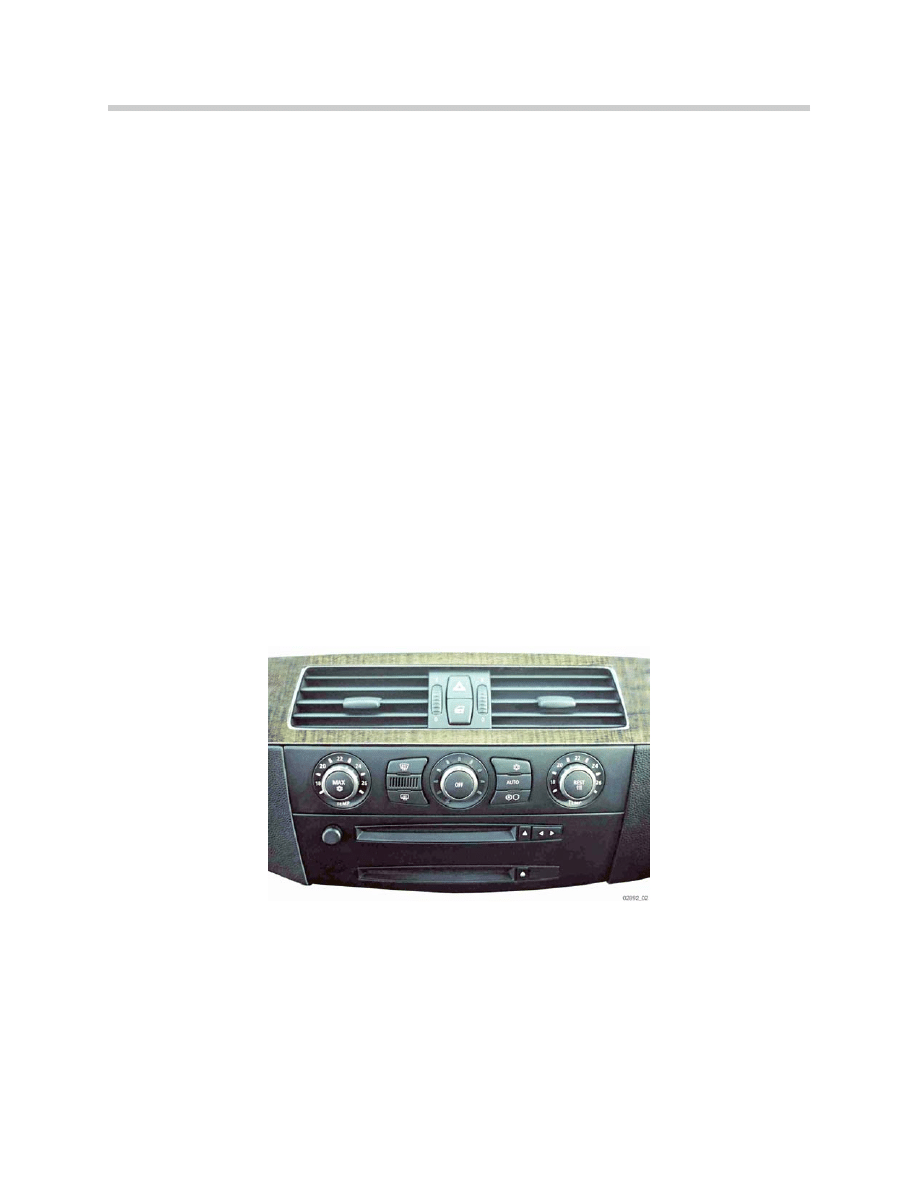
The car communication computer is the central control module for all applications. It is
always coupled with the 8.8" split-screen central information display. The car communi-
cation computer also features the high variant of the controller with haptic feedback.
The car communication computer is based on a modular design, i.e. the main systems of
the communication network are integrated in the form of modules in the car communica-
tion computer. It can be configured and expanded corresponding to requirements. At the
time of market launch, the following modules/functions will be integrated in the car com-
munication computer:
• Radio double tuner
• DVD navigation system, Professional (map presentation)
• Voice control system
• ASK functions
• MOST-CAN gateway functions
The following advantages are achieved by combining several control units in one module:
• Increased functionality by combining several systems
• Easy to expand/upgrade by means of software with corresponding interfaces
• Fewer plug connections therefore fewer potential fault sources
• Reduced package space for control units
3
E63/64 CCC
Components
The car communication computer consists of several components:
Housing
CD-ROM drive
DVD drive
HIP-module
(host independence
positioning module)
Gyro sensor
Tuner module
Main board
Power board
Audio board
Memory module
Front panel
Front panel with Bluetooth
module (not at SOP)
PMC-card 1 for rear
compartment entertainment
(not at SOP)
PMC-card 2 open
PCMCIA-card for memory
expansion (not at SOP)
Electric fan
4
E63/64 CCC
The car communication computer is accommodated in an
aluminium casing. The size of the car communication
computer corresponds to two radio DIN casings.
The following types of CD can be played on the CD-ROM
drive:
- Audio CD
- Audio CD-ROM with MP3 files
The gyro sensor is a separate module that is connect-
ed via plug contacts to the main board and is secured
by a screw.
The ASK functions are located on the audio board.
Two digital sound processors facilitate simultaneous
conditioning of the audio signals and operation of
the voice control system.
The power board is located at the rear of the car
communication computer. The FAKRA main con-
nector for the power supply and the MOST connec-
tor are secured on the power board. The main con-
nector provides the interface to the vehicle electrical
system.
The HIP module contains the GPS receiver that has the
task of converting and decoding the signals received from
the GPS aerial.:
When the navigation system is not in use, the DVD drive
can also be used to play audio CDs or audio CD-ROMs
with MP3 files.
In addition to the CPU (Central Processing Unit) fur-
ther processors and main memories are mounted
on the main board. The main board also contains
plug-in slots for expansion boards.

Rear view of car communication computer
5
E63/64 CCC
1. 12-pin connector, left
7. Cover for expansion card
2. 12-pin connector, right
8. LVDS connector
3. 16-pin connector
9. GPS aerial connector
4. MOST connector
10. Fan motor
5 . Cover for expansion card
11. Radio aerial connector
6. Connection for fan motor
1. Audio Board
2. Power Board
3. Main Board

Service Concept for the Car Communication Computer
The service concept is such that individual modules and parts of the car communication
computer can be replaced in the event of malfunction, thus serving to reduce repair
costs. A differentiation is made between electronic and mechanical parts.
Electronic Parts
Replacement of the following electronic parts is planned:
CD drive
DVD drive
Tuner module
HIP module
Gyro
Front panel
Audio board
Memory module
PMC cards
Electric fan
Mechanical Parts
Following mechanical parts are available:
Top cover
Bottom cover
DVD drive retaining fixture
CD retaining fixture
DVD drive holder
CD drive holder
Cover PMC slot
Cover PCMCIA slo
Rubber mount for electric fan
Particular attention must be paid to electrostatic discharge ESD when working on the car
communication computer. Disregard of the safety requirements may result in damage to
the electronic components in the car communication computer.
Working on Electronic Components
Preparatory Work
The following points must be observed when working on electronic components of the
car communication computer corresponding to the service concept.
All work must be carried out on a conductive and earthed workbench.
The special tool 12 7 192 is additionally used for this purpose.
The earthing cable must be connected to a secure and reliable earthing point (water pipe,
heating pipe, socket outlet earth). Before taking the parts out of their packaging, the per-
son working on the components must first put on the wrist cuff in order to discharge him-
self. The electronic components are placed on the antistatic mat and also connected with
the earthing cable.
6
E63/64 CCC
Replacement
The electronic components must be replaced as described in the repair instructions and
following the procedure described on SIP Electrostatic Fundamentals, while observing
ESD safety measures.
Note: The Antistatic Mat at your Center may look different than the one shown
here or at the training center. Remember the following when using the
Antistatic Mat:
•
Ground the Antistatic Mat to the workbench using the attached lead
•
Attach the Grounding strap to the component being serviced
•
Always wear the wrist cuff.
7
E63/64 CCC
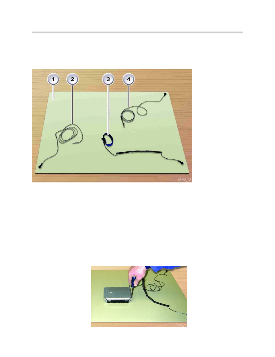
1. Antistatic Mat
2. Ground Strap
Antistatic Mat
3. Wrist Strap
4. Ground Strap
Component

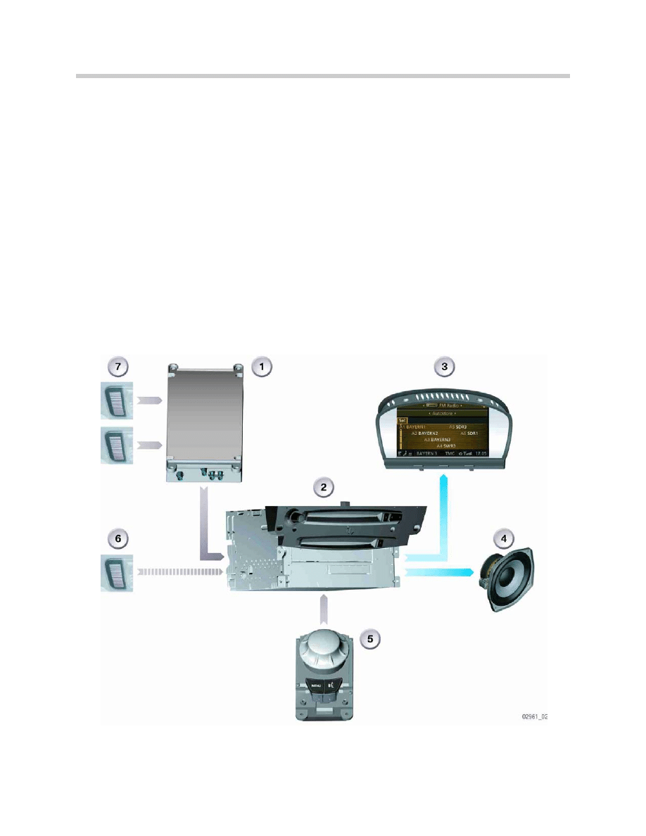
System Functions
The car communication computer comprises the following functions:
• Radio
• DVD navigation, Professional (map presentation)
• Voice control system
• Online platform
• Audio management
• ASK functions
• Driver for central information display
• MOST CAN gateway
Voice Control System
A voice control system High is integrated in the car communication computer. With this
system, all functions shown in the CID can be controlled by voice commands. This sys-
tem has the advantage that the hands need not be taken off the steering wheel while dri-
ving in order to change settings.
The SES can be used to control the following systems:
• Entertainment
• Communication
• Navigation
• Climate
• "5th Menu" setting
The voice control system makes use of specific voice commands. The voice control sys-
tem sets up a dialogue with the user. Repeat requests are issued if the system did not
understand a command.
System Integration
The voice control system is loaded as pure software in the car communication computer.
The voice control system makes use of the memories and processors in the car commu-
nication computers as well as the hardware of other systems (e.g. microphones).
The two hands-free microphones in the front roof console are used in connection with
the voice control system. The hands-free microphones are connected directly to the
telematics control unit (TCU). The TCU sends the microphone signals via MOST to the
car communication computer where they are processed in the DSP in order to execute
the required functions.
8
E63/64 CCC
Functional Principle of Voice Control System
System Start/End
The voice control system is activated/deactivated via the push-to-talk button (PTT) on
the multifunction steering wheel or on the controller. For the first time, the PTT button on
the controller makes it possible for the passenger to use the voice control system (SES).
The SES is activated for the driver by briefly pressing the button and for the passenger by
pressing and holding the button longer.
The SES is deactivated by again pressing one of the PTT buttons. Activation of the SES
is indicated by a graphic display (PTT logo) in the status line of the CID. The system is
active for about 5 seconds. If no input takes place during this period of time, the user is
informed that no voice input was detected and the request for voice input is repeated.
The voice control system is deactivated if again no input is made within 5 seconds.
9
E63/64 CCC
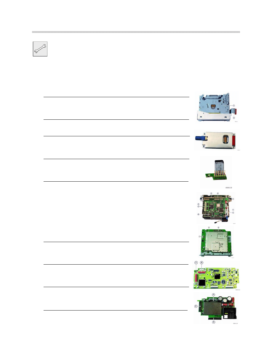
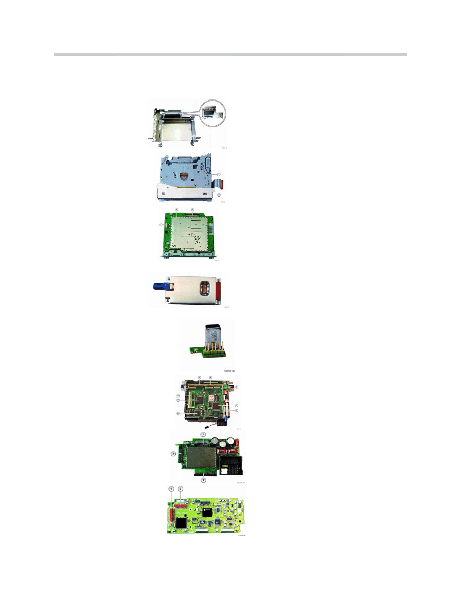
Workshop Exercise - CCC Disassembly
With the Instructor’s assistance, remove and disassemble the CCC mockup using
the Antistatic Mat.
1. Remove CCC face plate
2. Remove housing top plate and Tuner Module (on RH side)
3. Remove CD -ROM drive and disconnect harness
(shown on the right)
4. Turn CCC upside down and remove bottom cover plate
5. Remove HIP module - slide upwards and disconnect harness
(shown on the right)
6. Release single screw and remove the gyro sensor
(shown on the right)
7. Remove the Main Board surface screws
- disconnect top ribbon cables (3)
- disconnect bottom ribbon cables (2)
- release fiber optic connector from rear main plug block
(in housing)
- remove main board (shown on the right)
8. Remove DVD drive from the front
(shown on the right)
9. Remove Audio Board
(shown on the right)
10. Remove the power board by sliding it out of the housing
(shown on the right)
10
E63/64 CCC
Document Outline
- Main Menu
- E63-64 Complete Vehicle
- E63-64 Body Electrical
- E63-64 CCC
- E63-64 HUD
- E64 Convertible Top
Wyszukiwarka
Podobne podstrony:
02 E63 64 Body Electrical
04 E63 64 HUD
01 E63 64 Complete Vehicle
64 MT 03 Gladzica nastawna
03 Sejsmika04 plytkieid 4624 ppt
03 Odświeżanie pamięci DRAMid 4244 ppt
podrecznik 2 18 03 05
od Elwiry, prawo gospodarcze 03
Probl inter i kard 06'03
TT Sem III 14 03
03 skąd Państwo ma pieniądze podatki zus nfzid 4477 ppt
03 PODSTAWY GENETYKI
Wyklad 2 TM 07 03 09
więcej podobnych podstron