INSTRUCTION MANUAL
VHF TRANSCEIVER
UHF TRANSCEIVER
iF40GT/GS
iF30GT/GS
This device complies with Part 15 of the FCC rules. Oper-
ation is subject to the following two conditions: (1) This de-
vice may not cause harmful interference, and (2) this
device must except any interference received, including in-
terference that may cause undesired operation.

i
FOREWORD
Thank you for purchasing the IC-F30GT/GS,IC-F40GT/GS FM
transceiver.
READ ALL INSTRUCTIONS carefully and completely before using
the transceiver.
SAVE THIS INSTRUCTION MANUAL–This instruction manual
contains important operating instructions for the transceiver.
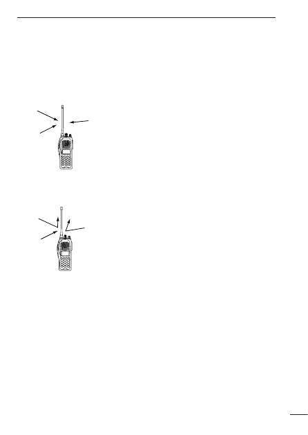
INSTALLATION NOTES
• When transmitting with a portable radio, hold the radio in a vertical
position with its microphone 2.5 to 5 centimeters (1 to 2 in.) away
from your mouth. Keep the antenna at least 2.5 centimeters (1 in.)
from your head and body.
• If you wear a portable two-way radio on your body, ensure that the
antenna is at least 2.5 centimeters (1 in.) from your body when
transmitting.
IMPORTANT
R
CAUTION! NEVER hold the transceiver so that the antenna is
very close to, or touching exposed parts of the body, especially the
face or eyes, while transmitting. The transceiver will perform best if
the microphone is 2 to 4 in. (5 to 10 cm) away from the lips and the
transceiver is vertical.
R
CAUTION! NEVER operate the transceiver with a headset or
other audio accessories at high volume levels.
R
CAUTION! NEVER short the terminals of the battery pack.
DO NOT push the PTT when not actually desiring to transmit.

AVOID using or placing the transceiver in direct sunlight or in areas
with temperatures below +14°F (–10°C) or above +122°F (+50°C).
The basic operations, transmission and reception of the transceiver,
are guaranteed within the specified operating temperature range
(depending on version). However, the LCD display may not be op-
erate correctly, or show an indication in the case of long hours of
operation, or after being placed in extremely cold areas.
DO NOT modify the transceiver for any reason.
KEEP the transceiver from the heavy rain, and Never immerse it in
the water. The transceiver construction is water resistant, not wa-
terproof.
The use of non-Icom battery packs/chargers may impair transceiver
performance and invalidate the warranty.
ii
FCC caution: Changes or modifications to this transceiver, not
expressly approved by Icom Inc., could void your authority to op-
erate this transceiver under FCC regulations.

iii
TABLE OF CONTENTS
FOREWORD . . . . . . . . . . . . . . . . . . . . . . . . . . . . . . . . . . . . . . . . . . . . .i
INSTALLATION NOTES . . . . . . . . . . . . . . . . . . . . . . . . . . . . . . . . . . . .i
IMPORTANT . . . . . . . . . . . . . . . . . . . . . . . . . . . . . . . . . . . . . . . . . . .i–ii
TABLE OF CONTENTS . . . . . . . . . . . . . . . . . . . . . . . . . . . . . . . . . . .iii
1 ACCESSORIES . . . . . . . . . . . . . . . . . . . . . . . . . . . . . . . . . . . . . . . .1
2 PANEL DESCRIPTION . . . . . . . . . . . . . . . . . . . . . . . . . . . . . . . .2–4
‘
Switches, controls, keys and connectors . . . . . . . . . . . . . . . . .2–3
‘
Function display . . . . . . . . . . . . . . . . . . . . . . . . . . . . . . . . . . . . . .4
3 BATTERY PACKS . . . . . . . . . . . . . . . . . . . . . . . . . . . . . . . . . . .5–10
‘
Battery pack replacement . . . . . . . . . . . . . . . . . . . . . . . . . . . . . .5
‘
Battery cautions . . . . . . . . . . . . . . . . . . . . . . . . . . . . . . . . . . . . . .6
‘
Battery charging . . . . . . . . . . . . . . . . . . . . . . . . . . . . . . . . . . .7–8
‘
Charging NOTE . . . . . . . . . . . . . . . . . . . . . . . . . . . . . . . . . . . . .9
‘
Battery case (Option) . . . . . . . . . . . . . . . . . . . . . . . . . . . . . . . .10
4 PROGRAMMABLE FUNCTIONS . . . . . . . . . . . . . . . . . . . . . .11–15
‘
General . . . . . . . . . . . . . . . . . . . . . . . . . . . . . . . . . . . . . . . . . . .11
5 CONVENTIONAL OPERATION . . . . . . . . . . . . . . . . . . . . . . . .16–18
‘
Receiving and transmitting . . . . . . . . . . . . . . . . . . . . . . . . . . . .16
‘
Call procedure . . . . . . . . . . . . . . . . . . . . . . . . . . . . . . . . . . . . . .17
‘
Tx code channel selection . . . . . . . . . . . . . . . . . . . . . . . . . . . . .18
‘
Manual 5-tone codes . . . . . . . . . . . . . . . . . . . . . . . . . . . . . . . . .18
‘
Transmitting notes . . . . . . . . . . . . . . . . . . . . . . . . . . . . . . . . . . .18
6 SmarTrunk II
TM
OPERATION . . . . . . . . . . . . . . . . . . . . . . . . . .19–21
‘
Basic operation . . . . . . . . . . . . . . . . . . . . . . . . . . . . . . . . . . . . .19
7 OTHER FUNCTIONS . . . . . . . . . . . . . . . . . . . . . . . . . . . . . . . . . . .22
‘
DTMF pager/Code squelch . . . . . . . . . . . . . . . . . . . . . . . . . . . .22
8 OPTIONAL UNIT INSTALLATION . . . . . . . . . . . . . . . . . . . . . . . . .23
‘
Installation . . . . . . . . . . . . . . . . . . . . . . . . . . . . . . . . . . . . . . . . .23
9 CLONING . . . . . . . . . . . . . . . . . . . . . . . . . . . . . . . . . . . . . . . . . . . .24
10 OPTIONS . . . . . . . . . . . . . . . . . . . . . . . . . . . . . . . . . . . . . . . .25–26
11 MEMO . . . . . . . . . . . . . . . . . . . . . . . . . . . . . . . . . . . . . . . . . . . . . .27
1
1
ACCESSORIES
‘
‘
Accessory attachment
D
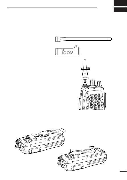
Supplied accessories
The transceiver comes supplied with the following accessories.
q
Flexible antenna (may
differ according to ver-
sion)
w
Belt clip
D
Antenna
The antenna screws onto the transceiver
as illustrated at right.
D
Belt clip
Attach the belt clip to the transceiver as illustrated below.
q
w
To release the belt clip
To attach the belt clip
2
PANEL DESCRIPTION
2
‘
‘
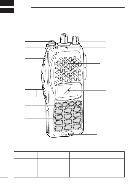
Switches, controls, keys and connectors
D
D
Programmable key reference
q
w
e
r
t
y
u
i
o
!0
!1
Microphone
Speaker
!2
F0 (Red)
F1 (Black)
F2 (Black)
F3 (Black)
P
0
P
1
P
2
P
3

3
2
PANEL DESCRIPTION
q
ANTENNA CONNECTOR
Connects the supplied antenna.
w
DEALER-PROGRAMMABLE KEY [F0 (Red)]
e
DEALER-PROGRAMMABLE KEY [F1 (Black)]
r
PTT SWITCH [PTT]
Push and hold to transmit; release to receive.
t
DEALER-PROGRAMMABLE KEYS [F2 (Black)], [F3 (Black)]
• Push to select the operating channel. Depends on setting.
• Can be programmed as [
✱
]/[ # ]. (SmarTrunk mode only)
y
DEALER-PROGRAMMABLE KEYS [P
0
]/[P
1
]/[P
2
]/[P
3
]
Can each be programmed for one of several functions by your
Icom Dealer.
u
10-KEY PAD (IC-F30GT/IC-F40GT only)
Used to enter DTMF codes, the operating channel, etc.
i
FUNCTION DISPLAY
Displays variety of information such as, operating channel num-
ber/names, 5-tone code, remaining battery power, DTMF num-
bers, transmit output power setting, Audible indication, etc.
NOTE: Above functions depend on pre-setting.
o
MULTI CONNECTOR
Connect optional speaker-microphone, etc..
!0
TRANSMIT/BUSY INDICATOR
Lights red while transmitting; lights green while receiving a sig-
nal, or squelch is open.
!1
VOLUME CONTROL [VOL]
Turns power ON and adjusts the audio level.
!2
ROTARY SELECTOR [SEL]
Selects operating channel or bank. Depends on setting.

PANEL DESCRIPTION
2
4
‘
‘
Function display
q
SIGNAL STRENGTH METER
Indicates relative signal strength level.
w
BANK NUMBER INDICATOR
Indicates operating bank (channel group) number.
e
LOW POWER INDICATOR
Appears when low output power is selected.
r
MULTI-FUNCTION INDICATOR
Indicates operating channel number, channel names, 5-tone
code, etc., according to operating condition.
t
SCRAMBLER INDICATOR
Appears while the voice scrambler function is activated.
y
KEY LOCK INDICATOR
Appears during key lock function ON.
u
BELL INDICATION
Appears or blinks when a 2/5Tone call is received.
i
AUDIBLE INDICATOR
Appears when monitor function is turned ON. (CTCSS and
DTCS mutes are released.)
o
BATTERY INDICATOR
Indicates remaining battery power.
q
w
e
r
t
y
u
i
o
5
3
BATTERY PACKS
‘
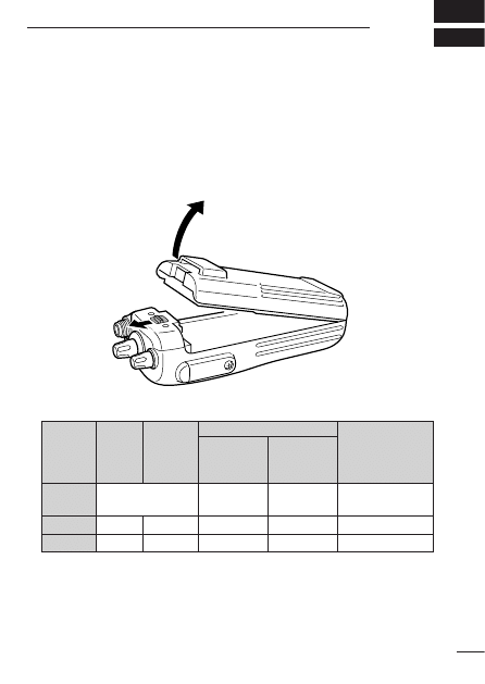
‘
Battery pack replacement
Before replacing the battery pack, the volume control MUST be ro-
tated fully counterclockwise, until a click is heard, to turn the power
OFF.
• Slide the battery release forward, then pull the battery pack up-
ward with the transceiver facing you.
D
D
BATTERY PACKS
*
1
Battery life is calculated under the following conditions;
Tx : Rx : standby =5 : 5 : 90
* Operating period depends on alkaline cells used.
Charging period
Battery
Voltage Capacity
BC-119 or
Battery life*
pack
BC-137
BC-121
with AD-94
BP-208
Battery case for AA
N/A
N/A
—
(R6)
×
6 alkaline
BP-209
7.2 V
1100 mAh
15 hrs.
1.5 hrs.
7 hrs.
BP-210
7.2 V 1650 mAh
15 hrs.
2.0 hrs.
11 hrs

6
3
BATTERY PACKS
‘
‘
Battery cautions
• CAUTION! NEVER short terminals (or charging terminals) of the
battery pack. Also, current may flow into nearby metal objects
such as a necklace, so be careful when placing battery packs (or
the transceiver) in handbags, etc.
Simply carrying with or placing near metal objects such as a neck-
lace, etc. causes shorting. This will damage not only the battery
pack, but also the transceiver.
• NEVER incinerate used battery packs. Internal battery gas may
cause an explosion.
• NEVER immerse the battery pack in water. If the battery pack be-
comes wet, be sure to wipe it dry BEFORE attaching it to the
transceiver.
• Clean the battery terminals to avoid rust or miss contact.
• Keep battery contacts clean. It’s a good idea to clean battery ter-
minals once a week.
If your battery pack seems to have no capacity even after being
charged, completely discharge it by leaving the power ON
overnight. Then, fully charge the battery pack again. If the battery
pack still does not retain a charge (or only very little charge), a new
battery pack must be purchased. (p. 9)
D
D
Recycling information (U.S.A. only)
The product that you have purchased contains a
rechargeable battery. The battery is recyclable. At
the end of its life, under various state and local
laws, it may be illegal to dispose of this battery into
the municipal waste stream. Call 1-800-822-8837
for battery recycling options in your area, or contact
your dealer.
7
3
BATTERY PACKS
‘
‘
Battery charging
D
Rapid charging with the BC-119+AD-94 (#02)
The optional BC-119 provides rapid charging of optional battery
packs.
The following are additionally required:
• One AD-94 (#02).
• An AC adapter (may be supplied with the BC-119 depending on ver-
sion)
.
When using the BC-119 in a vehicle: If the charge indicator
flashes orange, the vehicle battery voltage is low and charging
may not be performed. Check the vehicle battery voltage in this
case. If the charge indicator flashes red, there may be a prob-
lem with the battery pack (or charger). Re-insert the battery pack
or contact your dealer.
BC-119
+ AD-94 #02
Check orientation
for correct charg-
ing. (Insert togeth-
er with charging
adapter.)
Turn power
OFF.
8
3
BATTERY PACKS
D
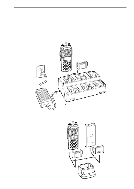
Rapid charging with the BC-121+AD-94 (#02)
The optional BC-121 allows up to 6 battery packs to be charged si-
multaneously. The following are additionally required.
• Six AD-94 (#02).
• An AC adapter (may be supplied with the BC-121 depending on version).
D
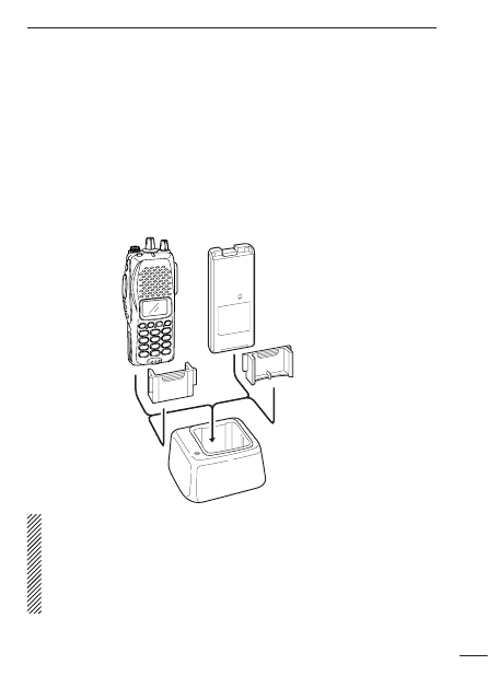
Regular charging with
the BC-137 #02
The optional BC-137 #02
provides regular charging
of optional battery pack
with/ without transceiver.
The following is addition-
ally required:
• An optional AC adapter.
(A charger adapter is sup-
plied with BC-137 #02.)
MULTI-CHARGER
AC adapter
(purchased
separately)
Charge indicator
(each indicator functions independently)
Turn power OFF.
Check orientation
for correct charg-
ing. (Insert togeth-
er with charging
adapter.)
Turn power OFF.
BC-137 #02

9
3
BATTERY PACKS
‘
‘
Charging NOTE
Prior to using the transceiver for the first time, the battery pack must
be fully charged for optimum life and operation.
• Recommended temperature range for charging:
+10°C to +40°C (50°F to 140°F).
• Use the supplied charger or optional charger (BC-119/BC-121 for
rapid charging, BC-137 #02 for regular charging)
only. NEVER use
other manufacturers’ chargers.
The optional BP-209 or BP-210 battery packs include rechargeable
Ni-Cd (Ni-MH: BP-210) batteries and can be charged approx. 300
times. Charge the battery pack before first operating the transceiver
or when the battery pack becomes exhausted.
If you want to charge the battery pack more than 300 times, the fol-
lowing points should be observed:
• Avoid over charging. The charging period should be less than
48 hours.
• Use the battery until it becomes almost completely exhausted
under normal conditions. We recommend battery charging after
transmitting becomes impossible.
D
D
Battery pack life
When the operating period becomes extremely short, even after
charging the battery pack fully, a new battery pack is needed.
10
3
BATTERY PACKS
‘
‘
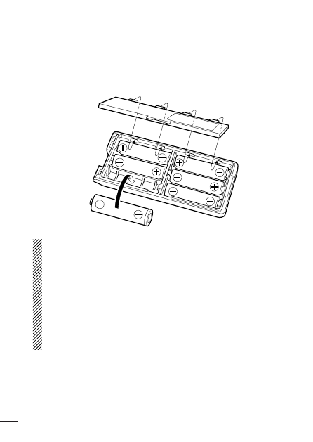
Battery case (Option)
When using an optional BP-208
BATTERY CASE
attached to the
transceiver, install 6 AA (R6) size alkaline batteries as illustrated
below.
D
D
CAUTION
• Use ALKALINE batteries only.
• Make sure all battery cells are the same brand, type and ca-
pacity.
• Never mix old and new batteries.
Either of the above may cause a fire hazard or damage the
transceiver if ignored.
• Never incinerate used battery cells since internal battery gas
may cause them to rupture.
• Never expose a detached battery case to water.
If the battery case gets wet, be sure to wipe it dry before use.

11
4
PROGRAMMABLE FUNCTIONS
‘
‘
General
In the following explanations, programmable function names are
bracketed, the specific switch used to activate the function depends
on programming.
D
D
KEYPAD LOCK FUNCTION
This function locks access to all programmable switches (except
the switch assigned for the lock function).
Push and hold the [Lock] switch for 1 sec. to toggle the lock function
ON and OFF.
• “
”appears while the lock function is ON.
• This function may be inhibited on some channels.
D
D
PRIORITY CHANNEL
This function is used to select a pre-programmed channel at the
push of a switch.
Push the [Priority A/A (Rewrite)/B] switch to select the priority chan-
nel.
• “Prio A” or “Prio B”appears briefly, then the priority channel is auto-
matically selected.
D
D
SCAN FUNCTION
The scan function allows you to search a pre-programmed group
of channels for signals.
Push the [Scan A/B] switch to start/stop scan.
• Scan pauses on a channel when receiving a signal.
• Depending on programming, a message may appear while scanning.
• “Lockout SCAN” (pre-programmed list SCAN) or “Priority SCAN” can
be pre-programmed.
• When the “Power-save function” is activated, the transceiver checks
all pre-programmed channels then returns to the “Power-save func-
tion” again.

12
4
PROGRAMMABLE FUNCTIONS
D
D
HIGH/LOW POWER OUTPUT
This function selects high or low power for a channel.
Push the [High/Low] switch to change transmit output power be-
tween high, low1 and low2 power.
• “
” appears when low1 or low2 output power is selected.
D
D
SCRAMBLER FUNCTION
(optional UT-109 (#02)* or UT-110 (#02)* is required.)
This function provides higher communication security.
UT-109: Non-rolling type. 32 code numbers are available.
UT-110: Rolling type. 1020 (4 groups
×
255) code numbers are
available.
Push the [Scrambler] switch to toggle the function ON and OFF.
NOTE: NEVER use #01 Low AF level versions, as they are not
compatible
13
4
PROGRAMMABLE FUNCTIONS
D
D
MONITOR AUDIBLE FUNCTION
The monitor function allows you to open the transceiver’s squelch
manually to check whether a channel is busy or not. The trans-
ceiver has 2 conditions for receive standby:
Audible condition:
This condition mutes audio ONLY when
no carrier is present. You can receive (or
monitor) any signals on a channel.
• Push and hold the [Moni] (LMR) or
[Moni (Audi)] (PMR) switch to select the
audible condition.
Any audio mute functions are cancelled
while pushing the [Moni] (LMR) or
[Moni (Audi)] (PMR) switch.
Inaudible condition:
This condition mutes ALL signals except
those directed to you. Therefore you
should check a channel’s condition (busy
or not) with the monitor function before
transmitting.
• Push the [Moni] (LMR) or [Moni (Audi)]
(PMR) switch momentarily to select the in-
audible condition.
D
D
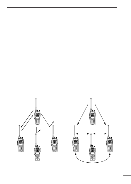
TALK AROUND
The talk around function changes duplex channels to simplex chan-
nels.
• Duplex allows you to contact your base station, repeaters, etc.
• Simplex allows you to contact other portable transceivers directly
(portable-to-portable contact).
Push the [Talk Around] switch to toggle the function ON and OFF.
All signals are received.
Only signals containing the
proper tone are received.

14
4
PROGRAMMABLE FUNCTIONS
D
D
DTMF TRANSMISSION
This function allows you to send a pre-programmed DTMF code to
control a repeater, open another transceiver’s squelch, etc.
Manual transmission:
Push the desired digit keys in sequence while pushing [PTT].
• Pushing [PTT] may not be necessary depending on programming.
Automatic pre-programmed transmission:
q
Push the [DTMF Autodial] switch to select DTMF autodial mode,
then push [CH Up] or [CH Down] to select the desired channel.
w
Push the [DTMF Autodial] switch to send a DTMF code.
D
D
DTMF RE-DIAL FUNCTION
This function allows you to transmit the last-used DTMF code at the
push of a key.
Push the [Re-dial] switch momentarily to activate the function.
• The previously transmitted DTMF code is automatically transmitted.
• If no code has been transmitted since turning the power ON, this func-
tion does not activate.
D
D
EMERGENCY FUNCTION
The emergency function allows you to send an emergency signal
quickly and easily to your Base Station, etc. in case of emergency.
Push and hold the [Emergency Single/Repeat] switch for 1 sec. to
activate the emergency function.
• The transceiver selects a pre-programmed channel, then sends an
emergency signal to your Base Station.
• The pre-programmed channel remains selected until a control signal is
received from the Base Station, or power is turned OFF.
• The emergency call is repeatedly transmitted at pre-programmed in-
tervals.

15
4
PROGRAMMABLE FUNCTIONS
D
D
DISPLAY LIGHTING
The function display has 3 backlight conditions.
ON
: Backlight turns ON continuously.
OFF
: No backlight is available.
AUTO
: When any key, except [PTT], is pushed, the backlight
turns ON for 5 sec. automatically.
D
D
SmarTrunk II
TM
functions
This transceiver provides SmarTrunk II
TM
functions.
(Optional UT-105
SmarTrunk II
TM
Logic Board
is required.)
The optional UT-105 allows communication over conventional
channels or SmarTrunk II
TM
channels. Select a channel bank for
SmarTrunk II
TM
before trunking operation.
To toggle SmarTrunk II
TM
channels and conventional channels, push
the [Bank] switch one or more times.
• Scanning starts when a channel bank for SmarTrunk II
TM
is selected.
• Contact your dealer for channel bank details.
(See p. 19 for more detailed operation.)

16
5
CONVENTIONAL OPERATION
‘
‘
Receiving and transmitting
NOTE: Transmitting without an antenna may damage the trans-
ceiver. See p. 1 for antenna attachment.
Turn power ON as described on p. 3.
Receiving:
q
Push [CH Up]/[CH Down], or rotate the [SEL] to select a chan-
nel.
w
Listen for a transmission and adjust [VOL] to a comfortable lis-
tening level.
• When no transmission is heard, push and hold monitor while ad-
justing [VOL] (your transceiver may not be programmed with the
monitor function).
The transceiver is now set to receive desired calls on the selected
channel.
Transmitting:
Wait for the channel to become clear to avoid interference.
e
While pushing and holding [PTT], speak into the microphone at a
normal voice level.
• When a tone signalling system is used, the call procedure de-
scribed at right may be necessary.
r
Release [PTT] to return to receive.
IMPORTANT: To maximize the readability of your transmitted sig-
nal, pause a few seconds. after pushing [PTT], hold
the microphone 2 to 4 in. (5 to 10 cm) from your
mouth and speak at a normal voice level.
17
5
CONVENTIONAL OPERATION
‘
‘
Call procedure
When your system employs tone signalling (excluding CTCSS and
DTCS)
, the call procedure may be necessary prior to voice trans-
mission. The tone signalling employed may be a selective calling
system which allows you to call specific station(s) only and prevent
unwanted stations from contacting you.
q
Select the desired Tx code channel or 5-tone code according to
your System Operator’s instructions.
• This may not be necessary depending on programming.
• Refer to the next page for selection.
w
Push the call switch (assigned to one of the dealer programma-
ble switches: [P
0
], [P
1
], [P
2
], [P
3
], [F2] and [F3]).
e
After transmitting a 5-tone code, the remainder of your commu-
nication can be carried out in the normal fashion.
Selective calling
Non-selective calling

18
5
CONVENTIONAL OPERATION
‘
‘
Tx code channel selection
Your radio may be programmed for Tx code channel selection. In
this case, you can choose a Tx code channel to be transmitted
when using the call function (p. 17).
Push [Tx Code CH Up/Down] (assigned to one of the dealer-pro-
grammable switches) to select the desired Tx code channel.
• The selected code channel (containing a pre-programmed 5-tone
code) is transmitted when using the call function.
‘
‘
Manual 5-tone codes
Depending on programming, you may be able to send 5-tone codes
manually.
Push [Tx Code] to activate the function, then enter the desired
transmit code (up to 7 digits) using the keypad.
• Activate the call function to transmit the 5-tone code.
• Blinking indicates keypad entry is acceptable.
‘
‘
Transmitting notes
D
D
TIME-OUT TIMER
After continuous transmission for a pre-programmed period, the
time-out timer is activated, causing the transceiver to stop trans-
mitting.
D
D
PENALTY TIMER
Once the time-out timer is activated, transmission is further in-
hibited for a period determined by the penalty timer.

19
6
SmarTrunk II
TM
OPERATION
‘
‘
Basic operation
These features are enabled by your Dealer or System operator and
may not be available in your system. Contact your Dealer for details.
Push the [Bank] switch one or more times to select a channel bank
for conventional channels or SmarTrunk II™ channels.
• Scanning starts when a channel bank for SmarTrunk II
TM
is selected.
D
D
PTT dispatch operation*
1
q
Push [PTT] once (without dialling) to initiate a dispatch call.
w
Begin talking after you hear three beeps (one short, high-
pitched, two very-short, low-pitched).
e
Receiving a dispatch call is indicated by the same three-beep
sequence.
• It is not necessary to push [
M
] to answer a dispatch call.
D
D
System busy indication
If all channels are busy, three low beeps sound after you initiate
a call. Try the call again later.
D
D
Receiving a subscriber-to-subscriber call*
1
When you hear ringing, push [
M
] to answer.
• For a group call, you hear a short ring followed by two short beeps.
You do not have to answer a group call to hear it over the air.
D
D
Receiving a landline-to-subscriber call*
1
When you hear ringing, push [
M
] to answer.
• For a group call, you hear a short ring followed by two short beeps.
You do not have to answer a group call to hear it over the air.
D
D
Terminating a call*
1
After completing a call, push [#] to disconnect (hang up).
IMPORTANT: If one person in the conversation terminates a call,
all participants will be cut off.

20
6
SmarTrunk II
TM
OPERATION
D
D
Last number redial*
1
Push [
M
], [
M
] to automatically redial the last number called.
• A high-pitched beep indicates that the number is accepted.
D
D
Turbo SpeeDial
To automatically dial a commonly used number with one push:
• Push one of the turbo SpeeDial keys.
D
D
Programming memory speed dial
q
Push and hold [
M
] until you hear a high-pitched beep.
w
Enter the memory location (0–9, A, B, C, D), the telephone or
subscriber number, then [1], [
M
] (or [3], [
M
] if for another sys-
tem subscriber).
• A high-pitched beep indicates successful programming.
• Memories [A]–[D] are used for the Turbo SpeeDial.
NOTE: This function is available for the IC-F30GT/IC-F40GT
only.
D
D
Memory speed-dialling*
2
To automatically dial a commonly used number from memory:
• Push [
M
] followed by the memory location (0–9).
D
D
Clear channel alerting*
1
If all channels are busy, the transceiver automatically begins
searching for an open channel and beeps every ten seconds.
When two short beeps (low-pitched, then high-pitched) are
heard, a channel is available. Push [
M
], [
M
] immediately to redial
the last number.
D
D
Emergency call*
2
Push [0], [
M
] to initiate an emergency call.
• Contact your Dealer for details.

21
6
SmarTrunk II
TM
OPERATION
D
D
Placing a telephone call*
2
Enter the phone number followed by [1], [
M
].
• A high-pitched beep indicates that the number is accepted.
• When the called party answers, push the [PTT] switch to talk, and
release it to listen.
D
D
Calling another local system subscriber*
2
Enter the subscriber number followed by [3], [
M
].
• A high-pitched beep indicates that the number is accepted.
• You hear ringing, then two short beeps when the subscriber an-
swers.
• If the other subscriber is on another call or out of range, you hear a
fast busy signal and the call terminates automatically.
*
1
: This function is available for the IC-F30GS/IC-F40GS when the
[F2]/[F3] keys are assigned the [
M
]/[ # ] key functions.
*
2
: This function is available for the IC-F30GT/IC-F40GT only.
Use the Turbo SpeeDial function instead.
For additional operating instructions, contact your Dealer or
System Operator.

22
7
OTHER FUNCTIONS
‘
‘
DTMF PAGER/CODE SQUELCH
D
D
DTMF pager
This function uses DTMF tones for calling and can be used as a
“common pager” to inform you that one of your group has called
even if the operator is temporarily away from the transceiver.
• When the connection code is received, a beep sounds, then “
”
flashes and shows the called stations code number.
• Called stations code number are memorized automatically, and
are
easy to re-call with “ID-MR select function”.
D
D
Code squelch
This conveniently eliminates unwanted audio and is useful in
group activities or security related activities where unwanted out-
put can be a problem. The function is similar to a CTCSS tone
squelch.
In order to use the above functions, cloning is necessary via a
PC using the optional CS-F30G
CLONING SOFTWARE
. Using this
software, the transceiver’s model, individual RX Code CH, TX
Code CH, Special Tone Link2 (must be ‘E’) in 5Tone screen,
5Tone Signaling Form in Memory-CH screen, Log, RX C-No,
Key&Display, Common Auto Reset Timer B, and other settings
related to operation can be set. Refer to the HELP file that comes
with the CS-F30G
CLONING SOFTWARE
for available settings.
23
8
OPTIONAL UNIT INSTALLATION
You can install two of the following optional units in the transceiver.
UT-105
SmarTrunk II
TM
Logic Board
, UT-109/UT-110
VOICE SCRAMBLER
UNIT
,
UT-111
TRUNKING BOARD
,
UT-113
MAN DOWN UNIT
.
‘
‘
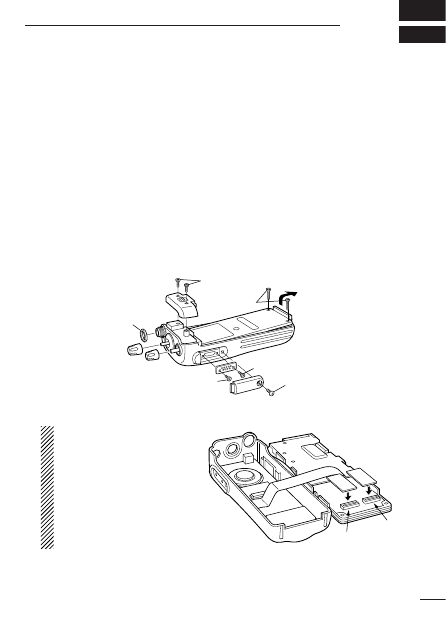
Installation
q
Unscrew nut
a
, and remove the knobs.
w
Unscrew screw
b
, 2 screws
c
then remove multi-connector
cover and rear panel.
e
Unscrew 2 screws
d
, then remove multi-connector.
r
Unscrew 2 screws
e
then separate the chassis from the front
panel in the direction of the arrow.
Be careful!: A flat cable is connected between the MAIN unit on the
chassis and front panel.
t
Install the desired optional unit. Insert tightly to avoid bad contact.
NOTE: When installing
UT-105 or UT-111, the
unit MUST BE plugged
into SLOT 1. Otherwise
the unit will not working
correctly. (Other optional
units can be plugged into
either slot.)
y
Program the necessary information with the cloning software before
operation. Please ask your dealer or system operator for details.
a
b
d
d
c
e
Slot 1
Slot 2

CLONING
24
9
‘
‘
Cloning
Cloning allows you to quickly and easily transfer the programmed
contents or data from PC to a transceiver using the optional CS-
F30G
CLONING SOFTWARE
.
D
D
PC-to-transceiver cloning
Please refer to the HELP file that comes with the CS-F30G
CLONING
SOFTWARE
.
CAUTION: Imprudent cloning operation causes a cloning error.
In such a case, memory contents may be lost. Cloning must
then be repeated.

25
10
OPTIONS
D
D
BATTERY PACKS
• BP-208
BATTERY CASE
Allows a set of Alkaline batteries to operate the handheld when
charging a rechargeable battery or in emergencies, etc. 6 AA (R6)
alkaline cells are required.
• BP-209
Ni-Cd BATTERY PACK
7.2 V/1100 mAh Ni-Cd battery pack, allows more than 7 hours op-
eration.
• BP-210
Ni-MH BATTERY PACK
7.2 V/1650 mAh Ni-MH battery pack, allows approx. 11 hours op-
eration.
D
D
CHARGER
• BC-137
BATTERY CHARGER
For regular charging of battery packs. An AC adapter is addition-
ally required. Charging time: 15 hrs.
• BC-119
DESKTOP CHARGER
+ AD-94 (#02)
CHARGER ADAPTOR
For rapid charging of battery packs. An AC adapter is supplied
with the charger. Charging time: 1.5 to 2 hrs.
• BC-121
MULTI
-
CHARGER
+ AD-94 (#02)
CHARGER ADAPTOR
(6 pcs.)
For rapid charging of up to 6 battery packs (six AD-94’s are re-
quired) simultaneously. An AC adapter may be supplied depend-
ing on version. Charging time: 1.5 to 2 hrs.
D
D
INTERNAL UNITS
• UT-105
SmarTrunk II
TM
Logic Board
Provides SmarTrunk II
TM
capabilities.
• UT-109 (#02)/UT-110 (#02)
SCRAMBLER UNITS
Non-rolling type (UT-109)/Rolling type (UT-110) voice scrambler
unit provides higher communication security.
• UT-111
TRUNKING BOARD
Provides LTR
®
trunking capabilities.
• UT-113
MAN DOWN UNIT
Provides a measure of safety when working in a hazardous envi-
ronment, etc.

26
10
OPTION
D
D
OTHER OPTIONS
• AD-52
EARPHONE JACK ADAPTER
Allows you to connect an earphone, 2-conductor 3.5 (d) mm (
1
⁄
8
″
).
• AD-98FSC
ANTENNA CONNECTOR CONVERTER
Allows you to connect an external antenna with BNC connector.
• EM-80/EM-89
SPEAKER
-
MICROPHONES
Combination speaker-microphone that provides convenient oper-
ation while hanging the transceiver from your belt.
• MB-68
BELT CLIP
Same as that supplied with the transceiver.
• MB-74
BELT CLIP
Exclusive alligator-type belt clip.
SmarTrunk II is a trademark of the SmarTrunk System Corporation. LTR is a reg-
istered trademark of EFJohnson Radio Systems.

27
11
MEMO

1-1-32 Kamiminami, Hirano-ku, Osaka 547-0003 Japan
A-5668H-1EX
Printed in Japan
© 2000 Icom Inc.
Wyszukiwarka
Podobne podstrony:
man ic pcr100
man ic q7a
man ic r75
man ic f1020 2020
man ic r2
man ic pcr100
man ic w32a
man ic f310 320 410 420
gs w07 id 197504 Nieznany
gs w05
GS pytania treningowe 1 0
GS 300 460, od 01 2005
gs w04 id 197501 Nieznany
Monitor Gold Star GS 556
GS~1, teologia skrypty, NAUKI HUMANISTYCZNE, JĘZYKI, J. GRECKI
GS Pytania zaliczenie stacjonarne 11 (1)
więcej podobnych podstron