
INSTRUCTION MANUAL
iC- f1020
VHF LAND MOBILE RADIO
iC- f2020
UHF LAND MOBILE RADIO
This device complies with Part 15 of
the FCC Rules. Operation is subject to
the condition that this device does not
cause harmful interference.

i
R
WARNING! NEVER
connect the transceiver to an
AC outlet. This may pose a fire hazard or result in an electric
shock.
NEVER
connect the transceiver to a power source of more
than 16 V DC such as a 24 V battery. This connection will ruin
the transceiver.
NEVER
cut the DC power cable between the DC plug and
fuse holder. If an incorrect connection is made after cutting,
the transceiver might be damaged.
NEVER
place the transceiver where normal operation of
the vehicle may be hindered or where it could cause bodily
injury.
NEVER
allow children to touch the transceiver.
NEVER
expose the transceiver to rain, snow or any liquids.
DO NOT
connect the transceiver to a power source using
reverse polarity. This connection will not only blow fuses but
also may damage the transceiver.
USE
supplied microphone only. Other microphones have
different pin assignments and may damage the transceiver.
CAUTIONS
IMPORTANT
READ ALL INSTRUCTIONS
carefully and com-
pletely before using the transceiver.
SAVE THIS INSTRUCTION MANUAL —
This
instruction manual contains important operating instructions
for the IC-F1020 and IC-F2020 LMR TRANSCEIVERS.
EXPLICIT DEFINITIONS
The following explicit definitions apply to this manual.
WORD
DEFINITION
R
WARNING
Personal injury, fire hazard or electric shock
may occur.
CAUTION
Equipment damage may occur.
NOTE
If disregarded, inconvenience only. No risk
of personal injury, fire or electric shock.
SmarTrunk II™ is a Trademark of SmarTrunk Systems, Inc.

ii
TABLE OF CONTENTS
IMPORTANT ........................................................................ i
EXPLICIT DEFINITIONS ..................................................... i
CAUTIONS ........................................................................... i
TABLE OF CONTENTS ...................................................... ii
1
PANEL DESCRIPTION ............................................. 1–5
■
Front panel ............................................................................ 1
■
Programmable function keys ................................................ 2
■
Function display .................................................................... 5
2
OPERATION ............................................................. 6–8
■
Turning power ON ................................................................. 6
■
Channel selection ................................................................. 6
■
Receiving and transmitting ................................................... 7
D
Transmitting notes ........................................................... 7
D
DTMF transmission ......................................................... 8
3
CONNECTION AND INSTALLATION .................... 9–12
■
Rear panel and connection ................................................... 9
■
Unpacking ........................................................................... 10
■
Mounting ............................................................................. 11
■
Separation .......................................................................... 11
■
Optional UT-105 installation ................................................ 12
4
OPTIONAL SmarTrunk II™ OPERATION ........... 13–15
■
SmarTrunk II™ and conventional modes ............................ 13
■
SmarTrunk II™ operation .................................................... 13
5
OPTIONS .................................................................... 16
DO NOT
use or place the transceiver in areas with tem-
peratures below –30°C (–22°F) or above +60°C (+140°F) or,
in areas subject to direct sunlight, such as the dashboard.
AVOID
operate the transceiver without running the vehicle’s
engine. The vehicle’s battery will quickly run out if the trans-
ceiver is in transmission while the vehicle’s engine OFF.
AVOID
placing the transceiver in excessively dusty envi-
ronments.
AVOID
placing the transceiver against walls. This will ob-
struct heat dissipation.
AVOID
the use of chemical agents such as benzine or al-
cohol when cleaning, as they damage the transceiver sur-
faces.
BE CAREFUL!
The transceiver will become hot when
operating continuously for long periods.
For U.S.A. only
CAUTION:
Changes or modifications to this transceiver,
not expressly approved by Icom Inc., could void your authority
to operate this transceiver under FCC regulations.
P
0
P
1
P
2
P
3
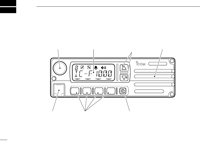
VOLUME CONTROL
MICROPHONE
CONNECTOR
FUNCTION DISPLAY
SPEAKER
POWER SWITCH
PROGRAMMABLE
FUNCTION KEYS
PROGRAMMABLE
FUNCTION KEYS
PANEL DESCRIPTION
1
1
■
Front panel

■
Programmable function keys
The following functions can be assigned to programmable
function keys. Assigned function names can be affixed to the
LCD using supplied stickers.
CHANNEL UP AND DOWN KEYS
• Select an operating channel
• Select a bank after pushing the [
BANK S
] key.
• Select a DTMF channel after pushing the [
DTMF
]
key.
• Select a scan group after pushing and holding the
[
SCAN
] key.
BANK UP AND DOWN KEYS
Select a bank (a group of 16 (or multiples of) chan-
nels).
• This function may be available for the optional 160 chan-
nel type only.
• When the optional UT-105 is installed, push one or more
times to select a channel bank for conventional channels
or SmarTrunk II™ channels.
1
PANEL DESCRIPTION
2
VOLUME CONTROL
Adjusts the audio output level.
• Minimum audio level (when setting control at maximum
counterclockwise) is pre-programmed.
POWER SWITCH
Turns the power ON and OFF.
• The following functions are available at power ON as op-
tions:
• Automatic scan start
• Password prompt
MICROPHONE CONNECTOR
Connects the supplied microphone or optional DTMF micro-
phone for SmarTrunk II™ operation here.
NEVER connect other microphones. The pin assignments
may be different and the transceiver may be damaged.
MICROPHONE
The supplied microphone has a PTT switch and a hanger
hook.
• The following functions are available when the microphone is
hung on or released form the microphone hanger:
• Automatic scan start when hung.
• Automatic priority channel selection when released.
• Turns OFF and ON the monitor function when hung or released
respectively.
CH UP
CH DN
BK UP
BK DN

1
SCAN TAG KEY
Adds or deletes the selected channel to the scan
group.
• “
” appears above the [
TAG
] key when the channel be-
longs to the scan group.
PRIORITY CHANNEL KEY
Selects a priority A or priority B channel with each
push.
LOCK KEY
Electronically locks all programmable keys except
the [
MONI
] and [
EMER
] keys.
MONITOR KEY
Activates the following functions on each channel in-
dependently:
• Push and hold the key to unmute the channel (audio is
emitted).
• Push the key to toggle the monitor function ON and OFF
(or ON only or OFF only depending on the pre-setting).
OUTPUT POWER SELECTION KEY
Selects the transmit output power temporarily or per-
manently depending on the pre-setting.
• Ask your dealer or system operator for the output power
level for each selection.
MONI
3
BANK SELECT KEY
Sets the [
CH UP
] and [
CH DN
] keys as bank up/down
keys.
• Push this key, then push the [
CH UP
] or [
CH DN
] to select
the desired bank.
• When the optional UT-105 is installed, push one or more
times to select a channel bank for conventional channels
or SmarTrunk II™ channels while pushing [
BK S
].
OPERATING CHANNEL KEYS
Select an operating channel directly without the [
CH
UP
] and [
CH DN
] keys.
SCAN START/STOP KEY
Push this key to start scanning; and push again to
stop.
NOTE: Hung the microphone to the microphone
hanger to operate scanning. When release the
microphone, scan will be canceled.
Push and hold this key to indicate the scan group,
then push [
CH UP
] or [
CH DN
] to select the desired
group.
PRI A
PRI B
SCAN
TAG
LOCK
HIGH
LOW2
LOW1
CH 3
CH 4
CH 1
CH 2
PANEL DESCRIPTION
BK S

1
4
TALK AROUND KEY
Turns the talk around function ON and OFF.
• The talk around function equalizes the transmit frequency
to the receive frequency for mobile-to-mobile communica-
tion.
EMERGENCY KEY
Push and hold the key to transmit an emergency call.
• An emergency call is transmitted for a specified period
after the “
” appears.
• If you want to cancel the emergency call, push (or push
and hold) the key again before transmitting the call.
• The emergency call is transmitted one time only or re-
peatedly until receiving a control code depending on the
pre-setting.
DTMF CHANNEL SELECT KEY
Push this key to select a DTMF channel.
• Push this key, then select the desired DTMF channel
using the [
CH UP
] or [
CH DN
] key.
Push and hold this key to transmit the selected
DTMF code.
NOTE: DTMF channels 6 and 7 are used for ID code and
emergency code respectively, depending on your system.
Ask your system operator or Dealer about DTMF channels
6 and 7 before using these DTMF.
T A
EMER
DTMF
PUBLIC ADDRESS KEY
When an optional OPC-617
ACC CABLE
is installed,
the audio output via the cable can be controlled from
the transceiver separately from the [
VOLUME
] control.
• This audio output can be used as a ‘public address’ func-
tion when an external audio amplifier and speaker are
connected additionally.
• Push this key, then speak into the microphone while push-
ing the PTT switch.
• The [
CH UP
] and [
CH DN
] keys allow you to set the audio
output level, from “ ” (minimum) to “
” (maximum).
EXTERNAL SPEAKER SWITCH
When external connections are made for the ‘public
address’ function, the external speaker drive function
is also available simultaneously. The received audio
can be heard via the external speaker when this key
is pushed.
• This function is useful when you are out of the vehicle.
• The audio output level is linked to the transceiver's volume
control.
P A
S P
PANEL DESCRIPTION
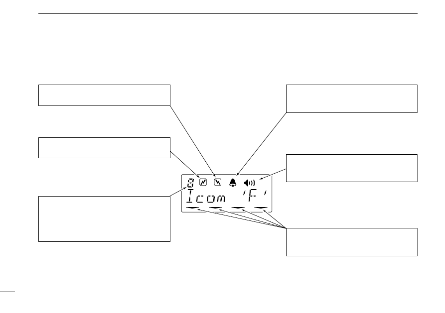
BUSY INDICATOR
Appears while the channel is busy.
TRANSMIT INDICATOR
Appears while transmitting.
AUDIBLE INDICATOR
Appears when monitor function is turned OFF
(CTCSS and DTCS mutes are released).
ACTIVATED KEY INDICATOR
Appears or blinks when the key under this
indicator is activated.
BELL INDICATOR
Appears or blinks when the optional 2-tone call
is received.
BANK NUMBER READOUT
Appears for the ‘Bank’ type and 180 channel
type only.
Shows the selected bank number or a hundred
digit to show more than 100 channels.
1
PANEL DESCRIPTION
5
■
Function display
■
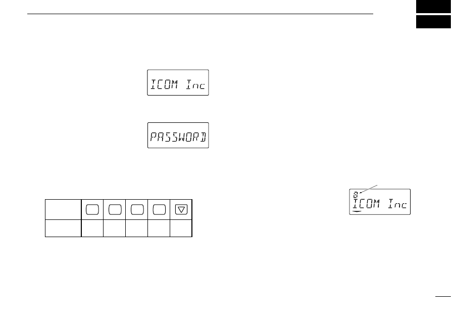
Turning power ON
q
Push
[K
I
]
to turn the power ON.
• A power-up alert tone sounds for
about 1 sec. and an opening mes-
sage may appears.
w
If the transceiver is programmed
for start up passcode, input digit
codes as directed by your sys-
tem operator.
• The following keys can be used for
the password input:
•
The transceiver detects the numbers in the same block as the
same number. Therefore the same effect for “1234” and “6789.”
e
When the “PASSWORD” indication does not clear after 4-
digit input, the input code number may be incorrect. Turn
power off and start over in this case.
■
Channel selection
There are several types are available, and channel selection
method may differ according to your system:
NON-BANK TYPE:
Push the [
CH UP
] or [
CH DN
] keys to select the desired oper-
ating channel, in sequence; or,
push one of the [
CH 1
] to [
CH 4
] keys to select these channels
directly.
BANK-TYPE:
q
Push [
BK S
], then push [
CH UP
] or [
CH DN
] to select the de-
sired bank number; or
Push [
BK UP
] or [
BK DN
] if the
transceiver has these keys.
w
Push [
CH UP
] or [
CH DN
] to select
the desired channel in the selected bank.
AUTOMATIC SCAN TYPE:
Channel setting is not necessary for this type. When turning
the power ON, the transceiver automatically starts scanning.
Scanning stops when receiving a call or taking the micro-
phone off from the microphone hanger.
OPERATION
2
6
Opening message may
differ depending on the
pre-setting.
Input your password if
this display appears.
Bank number
KEY
NUMBER
P
0
P
1
P
2
P
3
0
5
1
6
2
7
3
8
4
9

■
Receiving and transmitting
RECEIVING:
q
Push
[K
I
]
to turn the power ON.
w
Push [
CH UP
] or [
CH DN
] to select a channel.
e
When receiving a signal, adjust the volume to a comfort-
able listening level.
TRANSMITTING:
r
Hung off the microphone from the microphone hanger:
• CTCSS or DTCS may be released (“
” appears).
• A priority channel may be selected automatically.
t
Wait for the channel to become clear.
• The channel is busy when “
” appears.
y
While pushing and holding [PTT], speak into the micro-
phone at your normal voice level.
u
Release [PTT] to receive.
IMPORTANT:
To maximize the readability of your signal:
(1) pause briefly after pushing [PTT], (2) hold the trans-
ceiver 15 to 20 cm from your mouth, then speak into the
microphone with normal voice level.
2
OPERATION
7
D
Transmitting notes
• Transmit inhibit function
The transceiver has several lockout/inhibit functions which re-
stricts the transmission under the following conditions:
• Channel is busy.
• Not matched (or matched) CTCSS or DTCS is receiving.
• The selected channel is a ‘receive only’ channel.
• Time-out timer
After continuous transmission for a pre-programmed period,
the time-out timer is activated causing the transceiver to stop
transmitting and automatically select receive.
• Penalty timer
Once the time-out timer is activated, transmission is further
inhibited for a period determined by the penalty timer.

2
8
D
DTMF transmission
If the transceiver has [
DTMF
] key, the automatic DTMF trans-
mission function is available. Up to 7 DTMF channels may
be available.
q
Push [
DTMF
] to select the display
as at right.
w
Push [
CH UP
] or [
CH DN
] to select
the desired DTMF channel.
e
Push and hold [
DTMF
] to transmit the DTMF code in the
selected DTMF channel.
OPERATION
¤
⁄
‹
›
fi
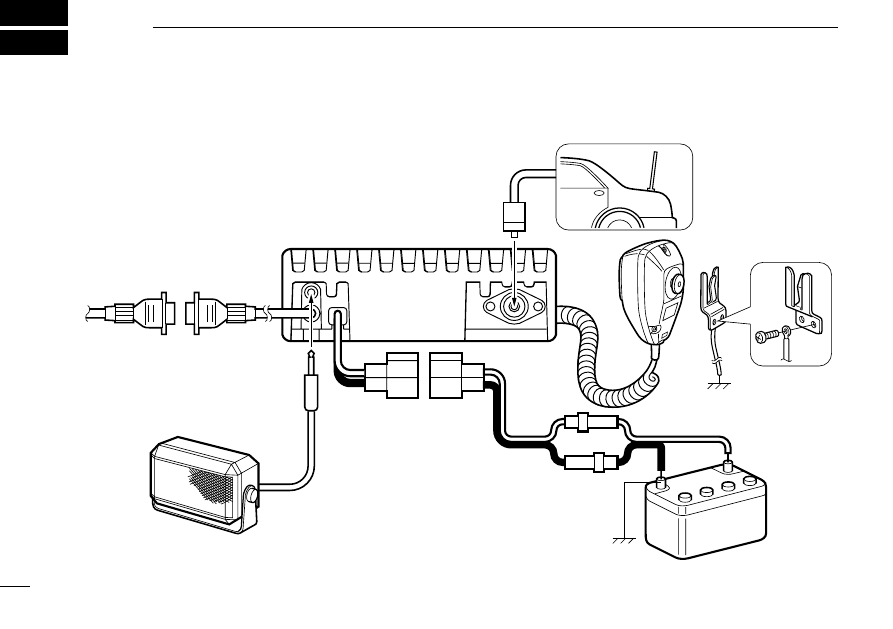
12 V
battery
black:
.
red:
,
Optional speaker
(SP-10)
Optional cable
(OPC-617)
Antenna
Supplied DC
power cable
CONNECTION AND INSTALLATION
3
9
■
Rear panel and connection
3
CONNECTION AND INSTALLATION
10
⁄
ANTENNA CONNECTOR
Connects to an antenna. Ask your dealer about antenna
selection and best installation location.
¤
MICROPHONE HANGER
Connect the supplied microphone hanger to the vehicle’s
ground for hanger function when hanging or releasing the
microphone.
‹
DC POWER RECEPTACLE
Connects to a 12 V DC battery. Pay attention to polarities.
NEVER
connect to a 24 V battery. This could damage the
transceiver.
›
EXTERNAL SPEAKER JACK
Connect a 4–8
Ω
external speaker, if desired.
fi
OPTIONAL CABLE (OPC-617)
Connect an external modem unit, LCD backlight control,
audio amplifier for ‘public address’ function, etc.
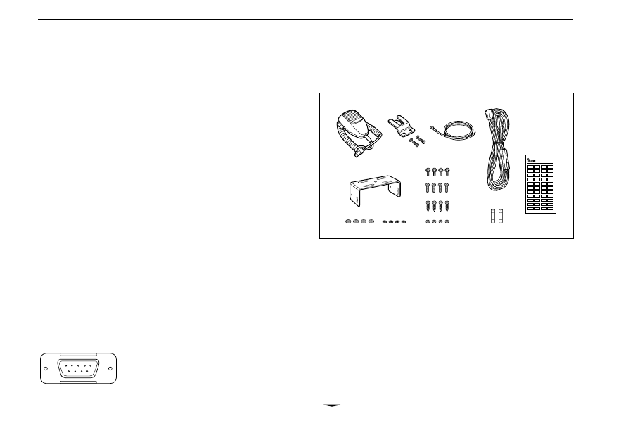
■
Unpacking
q
Microphone (EM-99) ......... 1
w
Microphone hanger and
screw set ..................... 1 set
e
Microphone cable .............. 1
r
DC power cable
(OPC-345) ......................... 1
t
Mounting bracket .............. 1
y
Bracket bolt ....................... 4
u
Mounting screw (M5
×
12) ... 4
i
Self-tapping screw
(M5
×
20) ............................. 4
o
Flat washer ....................... 4
!0
Spring washer ................... 4
!1
Nut .................................... 4
!2
Fuse (15 A) ....................... 2
!3
Function name sticker ....... 1
D
Function name sticker
There are no names on the programmable function keys
since the needed functions can be assigned to these keys.
Therefore, attach the supplied function name sticker on the
“
” indicator.
1
LCD backlit cont. IN
2
P-Adress AF OUT
3
Det. AF OUT
4
Mod. IN
5
PTT conrol IN
6
Horn drive cont. OUT
7
P-Adress AF GND
8
Det. AF GND
9
Mod. GND
54321
9 8 7 6
OPTIONAL CABLE PIN ASSIGNEMENT
1
2
3
4
5
6
7
8
9
0
A
B
C
LCD-STICKER
3
CONNECTION AND INSTALLATION
11
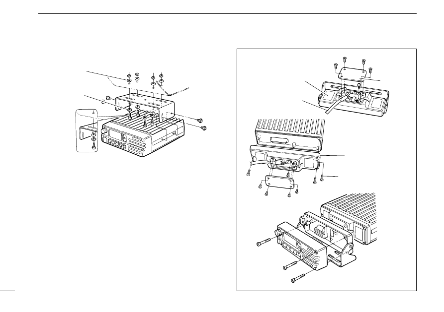
■
Mounting
■
Separation
q
Separate the front panel from the transceiver main unit
using an allen-wrench (1/32 in).
w
Connect the optional separation cable to the both front and
main unit attachments (fig. 1 and 2).
• Remove the rear plate of the attachment.
• Use the supplied screw to connect a cable lug.
• For the main unit attachment, attach to the main unit using sup-
plied screws, in advance.
e
Attach the front panel and attachment with the removed 3
allen socket bolts (fig. 3)
Fig. 1
Fig. 3
Fig. 2
Separation cable
OPC-607, OPC-608,
OPC-609 or OPC-726
Attachment
(for front panel)
Attachment
(for main unit)
Rear plate
Supplied screws
with the RMK-1
Flat washer
Spring washer
When using
self-tapping screws
• Separation (using RMK-1)
3
CONNECTION AND INSTALLATION
12
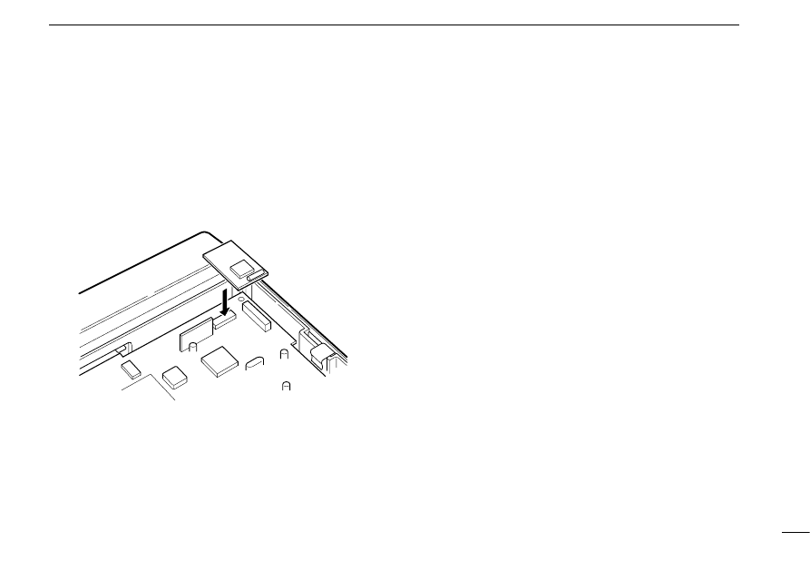
■
Optional UT-105 installation
The optional UT-105 provides SmarTrunk II™ functions. In-
stall the unit as follows:
q
Turn power OFF, then disconnect the DC power cable.
w
Unscrew the 4 screws, then remove the bottom cover.
e
Install the unit as shown in the diagram below.
r
Replace the bottom cover and screws, then the DC power
cable.
NOTE: The sponge supplied with the UT-105 is for the
IC-F30/F40 series transceivers only.

OPTIONAL SmarTrunk II™ OPERATION
4
13
■
SmarTrunk II™ and
conventional modes
This transceiver meets to SmarTrunk II™ functions.
The optional UT-105 allows communication in conventional
channels or SmarTrunk II™ channels. Select a channel bank
for SmarTrunk II™ before trunking operation.
• Push [
BK UP
] or [
BK DN
] one or more times to select a chan-
nel bank for conventional channels or SmarTrunk II™ chan-
nels.
• Pushing [
CH UP
] or [
CH DN
] while pushing [
BK S
] can also select
the channel bank.
• Scanning starts when a channel bank for SmarTrunk II™ is se-
lected.
• Contact your dealer for channel bank details.
NOTE: Connect an optional DTMF microphone. Contact
your dealer for details.
■
SmarTrunk II™ operation
These features are enabled by a dealer or system operator
and may not be available in your system. Contact your dealer
for details.
D
Placing a telephone call
Enter the phone number followed by [1], [
M
].
• A high-pitched beep indicates that the number is accepted.
• When the called party answers, push the [PTT] switch to talk, and
release it to listen.
D
Calling another local system subscriber
Enter the subscriber number followed by [3], [
M
].
• A high-pitched beep indicates that the number is accepted.
• You hear ringing, then two short beeps when the subscriber an-
swers.
• If the other subscriber is on another call or out of range, you hear a
fast busy signal and the call terminates automatically.
D
Receiving a call
When you hear ringing, push [
M
] to answer.
• For a group call, you hear a short ring followed by two short beeps.
You do not have to answer a group call to hear it over the air.

4
OPTIONAL SmarTrunk II™ OPERATION
14
D
Terminating a call
After completing a call, push [#] to disconnect (hang up).
IMPORTANT: If one person in the conversation terminates
a call, all participants will be cut off.
D
Last number redial
Push [
M
], [
M
] to automatically redial the last number called.
• A high-pitched beep indicates that the number is accepted.
D
Memory speed-dialing
To automatically dial a commonly used number from memory:
• Push [
M
] followed by the memory location (0–9).
D
Turbo SpeeDial
To automatically dial a commonly used number with one
push:
• Push one of the turbo SpeeDials ([A], [B], [C] or [D]).
D
Programming memory speed dial
q
Push and hold [
M
] until you hear a high-pitched beep.
w
Enter the memory location (0–9, A, B, C, D), the telephone
or subscriber number, then [1], [
M
] (or [3], [
M
] if for another
system subscriber).
• A high-pitched beep indicates successful programming.
• Memories [A]–[D] are used for the Turbo SpeeDial.
D
System busy indication
If all channels are busy, three low beeps sound after you initi-
ate a call. Try the call again later.
D
PTT dispatch operation
q
Push [PTT] once (without dialing) to initiate a dispatch call.
w
Begin talking after you hear three beeps (one short, high-
pitched, two very-short, low-pitched).
e
Receiving a dispatch call is indicated by the same three-
beep sequence.
• It is not necessary to push [
M
] to answer a dispatch call.
D
Emergency call
Push [0], [
M
] to initiate an emergency call.
• Contact your dealer for details.

4
OPTIONAL SmarTrunk II™ OPERATION
15
D
Clear channel alerting
If all channels are busy, the transceiver automatically begins
searching for an open channel and beeps every ten seconds.
When two short beeps (low-pitched, then high-pitched) are
heard, a channel is available. Push [
M
], [
M
] immediately to re-
dial the last number.
NOTE: For additional operating instructions, contact your
dealer or system operator.
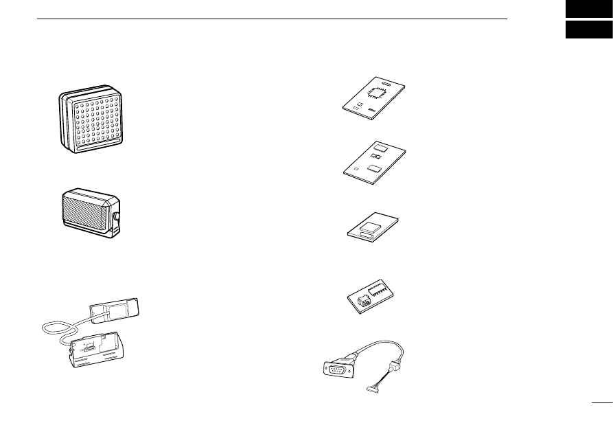
OPTIONS
5
EXTERNAL SPEAKERS
SP-5
Large speaker for good audio
quality.
Input impedance: 4
Ω
Max. input power: 5 W
SP-10
Compact and easy-to-install.
Input impedance: 4
Ω
Max. input power: 5 W
RMK-1 SEPARATION KIT and
SEPARATION CABLE
Allows you for separate installation
of the transceiver main unit and
front panel for easy installation
and good operation convenience.
SEPARATION CABLES:
OPC-607 (3 m), OPC-608 (8 m)
OPC-609 (1.9 m), OPC-726 (5 m)
16
UT-96 5-TONE DECODER UNIT
Provides for the 2-tone decode ca-
pability. The unit has 2 receive
channels with easy PC program-
ming.
UT-80 2-TONE DECODER UNIT
Provides for the 2-tone decode ca-
pability.
UT-105 SmarTrunk II™ Logic
Board
Provides for the SmarTrunk II™
capability.
EX-1761 MEMORY EXPANSION
UNIT
Provides the 160 channels for
large system operation.
OPC-617 ACC CABLE
Allows you to external terminal
connection.

A-5441S-1US
Printed in Japan
Copyright © 1995 by Icom Inc.
6-9-16 Kamihigashi, Hirano-ku, Osaka 547 Japan
Wyszukiwarka
Podobne podstrony:
man ic pcr100
man ic f30gt gs f40gt gs
man ic q7a
man ic r75
man ic r2
man ic pcr100
man ic w32a
man ic f310 320 410 420
400 man
man ar900
IC zamienniki eu ru tomsk id 20 Nieznany
Przegląd układu tłokowo – korbowego silnika MAN B&W – L 2330 H
Procol Harum The Dead Man's Dream
43. de Man, teoria literatury!!!
Raport z negocjacji budżetowych UE 14 2020
Cyberpunk 2020 Slang
więcej podobnych podstron