
CSM CUTTER SOIL MIXING - A NEW TECHNIQUE FOR THE
CONSTRUCTION OF SUBTERRANEAN WALLS
INITIAL EXPERIENCES GAINED ON COMPLETED PROJECTS
E. Stoetzer, F.-W. Gerressen, M. Schoepf, BAUER Maschinen, Schrobenhausen, Germany
Introduction
Bauer Maschinen GmbH developed the CSM
technique in 2003 by drawing on the
experience gained in the production and
deployment of diaphragm wall cutters in the
construction of cut-off and diaphragm retaining
walls.
The CSM System differs essentially from
traditional techniques, in which the existing soil
is mixed in-situ with self-hardening slurry by
mixing tools rotating about a vertical axis, by
using a mixing tool that rotates about a
horizontal axis.
Construction principle
The soil is mixed with self-hardening slurry,
which is simultaneously introduced into the soil
mass, to produce a wall construction material
that takes on the role of a cut-off or structural
retaining wall.
The following construction sequence is
generally adopted:
a) Construction of a good sized open guide
trench for retaining excess slurry.
b) Fluidization of the soil mass during
penetration to the terminal depth as an
appropriate slurry is simultaneously
introduced. Depending on the prevailing
conditions, either bentonite slurry is added to
the mixing and fluidization process or cement
slurry is introduced into the soil during
penetration. The volume of slurry injected is
determined by the rate of cutter penetration.
c) During withdrawal, the precise volume of
slurry required for producing the final wall
construction material is injected.
d) A continuous wall is formed by the
construction of individual panels in an
alternating sequence of overlapping primary
and secondary panels. Secondary panels can
be constructed immediately after completion of
primary panels, i.e. „soft-into-soft“. The cutter
technology does, however, also enable cutting
into panels that have already hardened, i.e.
„soft-into-hard".
e) To utilize the wall as a structural retaining
wall, steel columns (IPB sections) are inserted
into the freshly mixed wall panels.
Plant and equipment
The size of individual panels is determined by
the type and size of equipment being
deployed. Panels can be constructed in
lengths ranging from 2.2 m to 2.8 m and wall
thicknesses of 0.5 m to 1.0 m.
In all known soil mixing processes the existing soil is mixed with self
hardening slurry by mixing tools that rotate about a vertical axis (augers,
mixing paddles). Wall panels are constructed using sets of triple mixing
tools combined into a single unit. These techniques have been developed
on the principle of the rotary drilling technology. In contrast, the new Cutter
Soil Mixing or CSM technique is derived from the cutter technology.
The soil is loosened and broken down by cutter wheels then mixed in-situ
by the rotating cutter wheels with the self-hardening slurry - introduced into
the ground between the two wheels - to form a soil-slurry mortar. The main
area of application lies in the construction of cut-off and retaining walls.
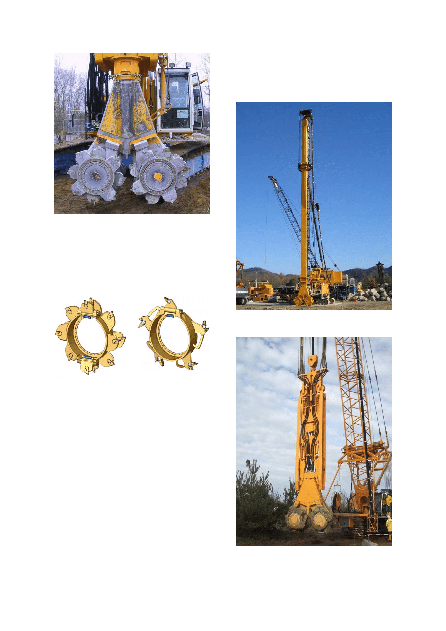
Fig. 1 Mixing wheels and housing for
hydraulic gear drives
The most important elements of the CSM unit
are the cutter gear drives. They are driven by
hydraulic motors which are located in a water-
tight housing.
Fig. 2 Types of wheels
For loosening and mixing the soil different
types of mixing wheels were developed.
Selection of the correct wheel and set of teeth
is the main pre-condition for cost-effective
operation, minimal wear and for obtaining a
homogeneous soil-slurry mixture.
The slurry is introduced into the soil directly
between the mixing wheels. During
construction, the counter-rotating mixing
wheels and vertically mounted plates are
effectively acting like a forced action mixer.
The mixing unit is either mounted on a guided
Kelly bar or on a wire rope-suspended cutter
frame equipped with special steering devices.
The standard set-up is the "Kelly-guided"
variant capable of reaching depths up to 35 m.
"Rope-suspended" systems are particularly
suited for construction of deep soil mix walls.
The greatest depth at which a wire rope-
suspended unit has successfully installed a
soil mix wall to date is 55 m.
Fig. 3 Kelly-guided CSM unit (Japan)
Fig. 4 Wire rope-suspended frame-mounted
CSM unit (Germany)
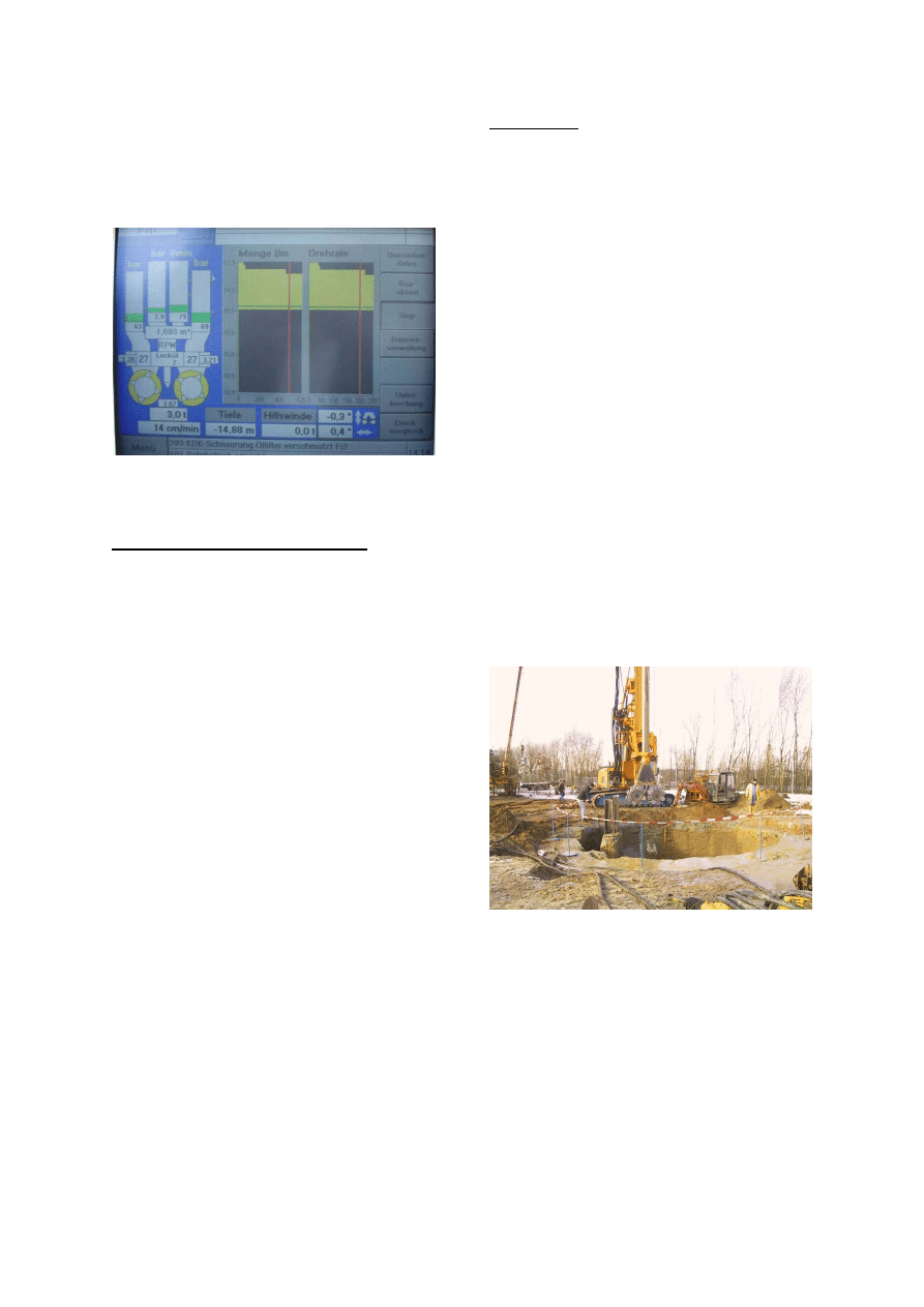
Both systems must be accompanied by an
intensive quality assurance programme. All
process-specific production and plant-specific
operating data are visualised throughout the
construction phase and stored for subsequent
documentation and evaluation.
Fig. 5 Rig operator’s on-board computer
screen
Comparison with other techniques
The CSM process has significant advantages
over conventional techniques:
The existing soil is utilised as construction
material.
Very little spoil material is generated; this
renders the technique particularly suited for
work on contaminated sites.
CSM is an ideal alternative to the "Berlin"
retention wall system in high groundwater
conditions, or to sheet pile walls in soil
formations unsuitable for pile driving or in
close proximity to vibration-sensitive buildings.
Wall depths of 25 m and daily production rates
of 200 m² can be achieved with relatively light
base machines of 70 – 90 tones total
operating weight and installed power outputs
of 260 – 300 kW.
A high degree of verticality of wall panels is
achieved by the counter-rotating cutter wheels.
The cutter principle ensures construction of
clean and trouble-free joints even between
wall panels of different construction age e.g.
after weekend breaks or prolonged stoppages
on site.
Harder soil formations can be easily
penetrated, broken down and mixed by using
the cutter wheels as cutting and mixing tool.
First results
Between December 2003 and January 2004,
feasibility tests were carried out at the BAUER
Maschinen test site in Aresing with the aim to
construct watertight retaining walls to depths
of up to 20 m using a new soil-mixing process.
The soil at the test site consists essentially of
a 6 m thick layer of gravelly sand and an
underlying mass of fine sands and silts. The
ground-water level stands at approx. 3 m
below ground level.
The feasibility tests were carried out in co-
operation with the specialist foundation
contractor Soletanche-Bachy of France.
To develop the technique into a construction
process for full scale production, a quasi
circular wall in the shape of polygon was
constructed with a diameter of 8 m and a
depth of 20 m. The loads imposed by both
earth and hydrostatic pressure are carried
through the circular vault effect. Neither
reinforcement nor steel sections were inserted
into the wall. The shaft was excavated to a
depth of 10 m. All wall panels and joints are
watertight. Compressive strengths of 6-10
MPa were attained.
Fig. 6 Test site Aresing CSM rig and
completed shaft
The CSM system was showcased at BAUMA
2004 in Munich, Germany, where it received
the "Innovation Price of the German
Construction Machinery Day 2004"
(Innovationspreis des Deutschen Bau-
maschinentages 2004). At BAUMA 2004, the
system was immediately taken up by a
Japanese client, who subsequently carried out
a series of feasibility tests with the technical
support of BAUER Maschinen to examine
possible applications under Japanese
conditions.
The soil conditions in which these tests were
carried out were typical for Greater Tokyo:
a 7 m thick very soft clay layer underlain by
loose (interbedded layers of medium dense)
silty fully saturated fine sands.
The work was carried out based on criteria
commonly applied in Japan (mix with a high
w/c ratio, high pump volumes with high
proportion of return flow). The results show
that the requirements were clearly satisfied:
High soil mixing outputs were achieved (up to
40 m³/h).
Steel sections were inserted without difficulty
to the design depth of 15 m.
The clay layer resulted in a much more
homogenous mix when compared with other
techniques commonly used in Japan.
Fig. 7 Soil-cement slurry whirled up by the
addition of air during penetration phase
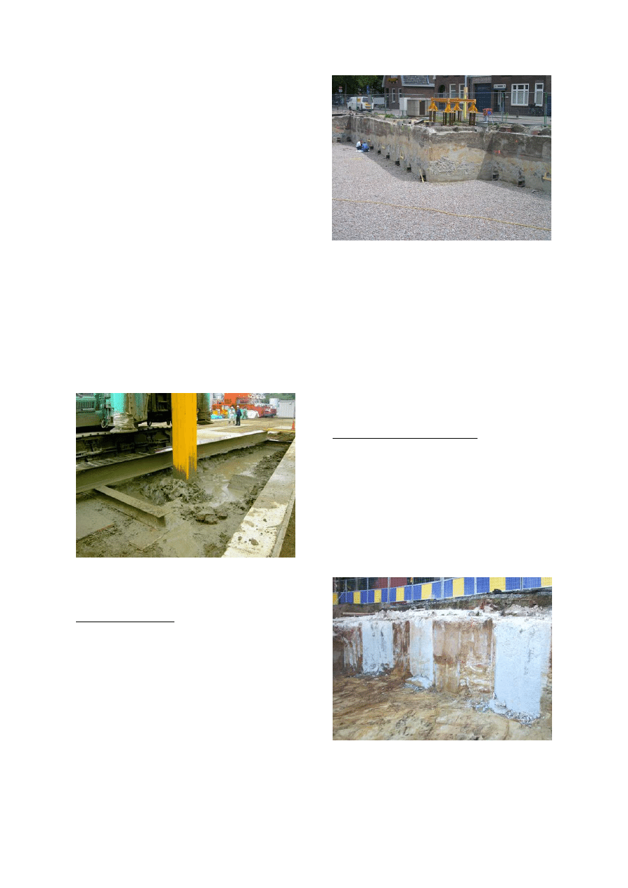
Completed projects
After the initial experience gained in 2004, a
total of 25 projects were carried out world-wide
in 2005.
The projects were concentrated in the Benelux
countries (Fig 8), Italy and the classic soil mix
country, Japan. Here, the most diverse
applications were found for the CSM process,
whereby the clients of Bauer Maschinen
GmbH showed also a high degree of creativity.
Fig. 8 Retaining wall constructed by
the CSM process (The Netherlands)
Besides the classic application of the
technique as retaining and cut-off wall, CSM
panels were also deployed as foundation
elements. A further test was to show, whether
soils, which are unsuitable for vibratory pile
driving techniques, can be treated in-situ by
the CSM system to facilitate subsequent
driving of sheet piles. The wire rope-
suspended CSM unit provided positive results
for soil mixing at depths of up to 55 m.
CSM as foundation elements
On several building projects CSM panels were
used as foundation elements. Apart from the
main advantages of the CSM process, such as
the use of the existing subsoil as construction
material and the minimized spoil removal, a
further advantage results from the fact that the
same equipment can be deployed to construct
first the retaining wall for the excavation and
then the foundation elements.
Fig. 9 Wall panels with integrated foundation
elements
To date, the technique has been used in
different variations. On one of the projects, for
example, foundation elements were
constructed concurrently with the retaining wall
and connected with each other in such a way
that the retaining wall was subsequently also
capable of carrying vertical loads. (Fig. 9)
On another project, CSM panels reinforced
with tension bars were used as uplift anchors
to tie-down a raft foundation in adverse
groundwater conditions.
Fig 10 CSM wall and CSM panels reinforced
with tension bars used as uplift anchors
CSM as ground treatment technique
As part of a proposed scheme to prevent
contaminants escaping from a refinery in
Sicily
,
a sheet pile wall was to be installed to a
depth of 18 m. Construction of the seepage
prevention scheme by way of conventional
cut-off techniques was not possible, as the
highly contaminated subsoil could not be
removed off site.
The ground conditions were not suitable,
however, for conventional sheet pile wall
installation:
0 - 5m
sandy fill (made ground)
5m - 10m
cemented sands
below 10 m
clay
The cemented sand layers proved to be a
significant obstacle to pile driving. The largely
weathered formation was interbedded with
non-weathered bands with unconfined
compressive strength values of up to 40 MPa.
The task of the CSM process was to prepare
the soil to the top of the clay layer in-situ so
that (a) excavation of the soil would be
avoided, and (b) subsequent installation of the
sheet pile wall would be assured.
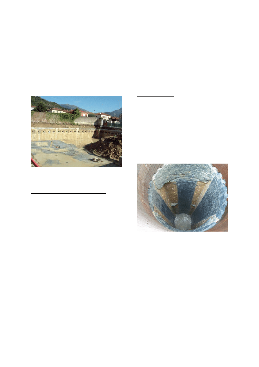
Deep CSM panels
After a series of trials in Germany and Japan
using the wire rope-suspended CSM method
for greater depths, a shaft was constructed for
the Quality Assurance Department of Bauer
Maschinen. The shaft is to provide a facility for
testing Kelly bars from our own production line
under site conditions. For this purpose, four
CSM panels were constructed to a depth of 55
m to form a rectangular shaft, the inside of
which was subsequently drilled out to a depth
of 50 m.
Fig.11 Excavated shaft (depth 55 m)
supported by four CSM panels
Construction of the shaft was carried out by
the two-stage technique. During penetration of
the mixing tool the soil is fluidized and mixed
with bentonite slurry (Fig. 12).
During withdrawal of the mixing tool the final
wall construction material is product by the
introduction of cement slurry (Fig. 13).
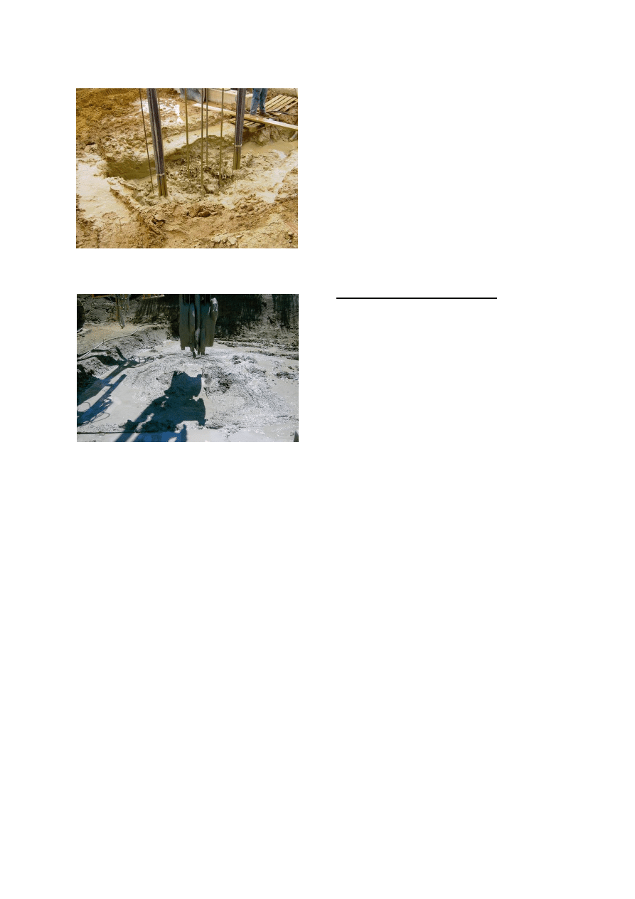
Fig. 12 Fluid soil-bentonite backflow
Fig. 13 Finished panel (overflow soil-cement)
The main advantage of the two-stage
construction technique is the fact that
production of a panel can be interrupted during
penetration without any problem, i.e. for a shift
change, and subsequently be resumed by re-
entering the pre-mixed trench. Only after
having reached the terminal depth and
switched to cement slurry the completion of
the panel in a single operation is
advisable.Treatment of the discharged soil-
bentonite mud is facilitated by the additional
deployment of a mud regeneration plant. The
cleaned bentonite can be re-cycled for reuse
and the extracted soil particles can be
removed off site.
Conclusions and future outlook
The above examples have demonstrated that
a new construction technique, which combines
the advantages of the cutter and soil mixing
technology has been successfully established
in the market. The technique offers a great
diversity of possible applications, such as cut-
off walls, structural retaining walls foundation
elements and numerous others.
The capacity to reach great depths offers an
enormous potential for the construction of
deep cut-off walls for dams or the en-
capsulation of contaminated sites.
Wyszukiwarka
Podobne podstrony:
Analysis of soil fertility and its anomalies using an objective model
8956 8957 Cave Cutter
Concrete Mixing
2a Soil compaction USDA NRCS 96
Compost Soil 847 1538 1 PB
THE IMPORTANCE OF SOIL ECOLOGY IN SUSTAINABLE AGRICULTURE
Fog Cutter
soil
Analysis of soil fertility and its anomalies using an objective model
8956 8957 Cave Cutter
Concrete Mixing
Ecological effects of soil compaction and initial recovery dynamics a preliminary study
Mixing It Up2
mixing the punch
Mixing it Up
Concrete Mixing
The Native Soil Alan E Nourse
980359 001A Cutter UG en
więcej podobnych podstron