Lecture Notes: Introduction to Finite Element Method
Chapter 2. Bar and Beam Elements
© 1998 Yijun Liu, University of Cincinnati
58
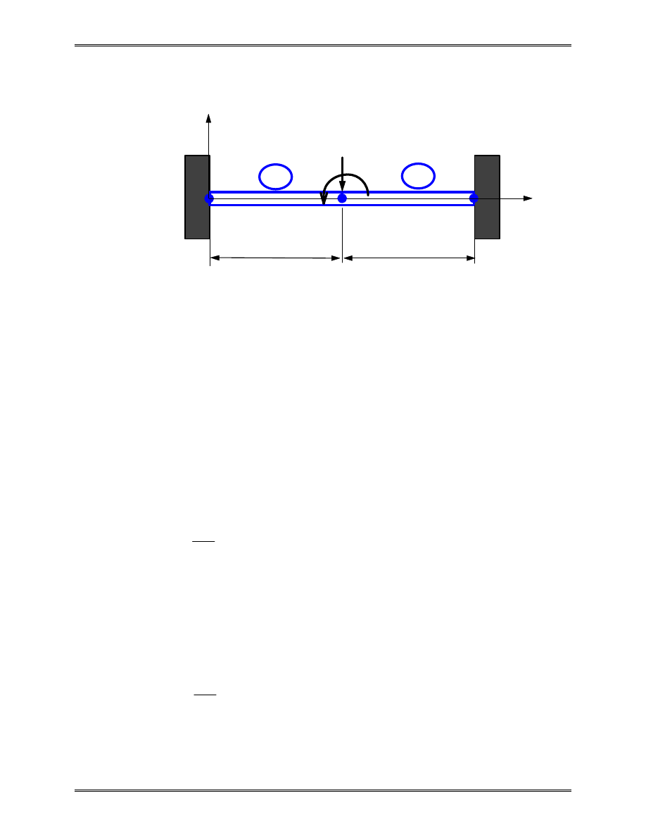
Example 2.5
Given:
The beam shown above is clamped at the two ends and
acted upon by the force P and moment M in the mid-
span.
Find:
The deflection and rotation at the center node and the
reaction forces and moments at the two ends.
Solution: Element stiffness matrices are,
v
v
EI
L
L
L
L
L
L
L
L
L
L
L
L
L
1
1
2
2
1
3
2
2
2
2
12
6
12
6
6
4
6
2
12
6
12
6
6
2
6
4
θ
θ
k
=
−
−
−
−
−
−
v
v
EI
L
L
L
L
L
L
L
L
L
L
L
L
L
2
2
3
3
2
3
2
2
2
2
12
6
12
6
6
4
6
2
12
6
12
6
6
2
6
4
θ
θ
k
=
−
−
−
−
−
−
L
X
1
2
P
E,I
Y
L
3
M
1
2
Lecture Notes: Introduction to Finite Element Method
Chapter 2. Bar and Beam Elements
© 1998 Yijun Liu, University of Cincinnati
59
Global FE equation is,
v
v
v
EI
L
L
L
L
L
L
L
L
L
L
L
L
L
L
L
L
L
L
L
L
v
v
v
F
M
F
M
F
M
Y
Y
Y
1
1
2
2
3
3
3
2
2
2
2
2
2
2
1
1
2
2
3
3
1
1
2
2
3
3
12
6
12
6
0
0
6
4
6
2
0
0
12
6
24
0
12
6
6
2
0
8
6
2
0
0
12
6
12
6
0
0
6
2
6
4
θ
θ
θ
θ
θ
θ
−
−
−
−
−
−
−
−
−
−
=
Loads and constraints (BC’s) are,
F
P
M
M
v
v
Y
2
2
1
3
1
3
0
= −
=
=
=
=
=
,
,
θ θ
Reduced FE equation,
EI
L
L
v
P
M
3
2
2
2
24
0
0
8
=
−
θ
Solving this we obtain,
v
L
EI
PL
M
2
2
2
24
3
θ
=
−
From global FE equation, we obtain the reaction forces and
moments,

Lecture Notes: Introduction to Finite Element Method
Chapter 2. Bar and Beam Elements
© 1998 Yijun Liu, University of Cincinnati
60
F
M
F
M
EI
L
L
L
L
L
L
L
v
P
M L
PL
M
P
M L
PL
M
Y
Y
1
1
3
3
3
2
2
2
2
12
6
6
2
12
6
6
2
1
4
2
3
2
3
=
−
−
−
−
=
+
+
−
−
+
θ
/
/
Stresses in the beam at the two ends can be calculated using the
formula,
σ σ
=
= −
x
My
I
Note that the FE solution is exact according to the simple beam
theory, since no distributed load is present between the nodes.
Recall that,
EI
d v
dx
M x
2
2
=
( )
and
dM
dx
V
V
dV
dx
q
q
=
=
(
(
- shear force in the beam)
- distributed load on the beam)
Thus,
EI
d v
dx
q x
4
4
=
( )
If q(x)=0, then exact solution for the deflection v is a cubic
function of x, which is what described by our shape functions.
Lecture Notes: Introduction to Finite Element Method
Chapter 2. Bar and Beam Elements
© 1998 Yijun Liu, University of Cincinnati
61
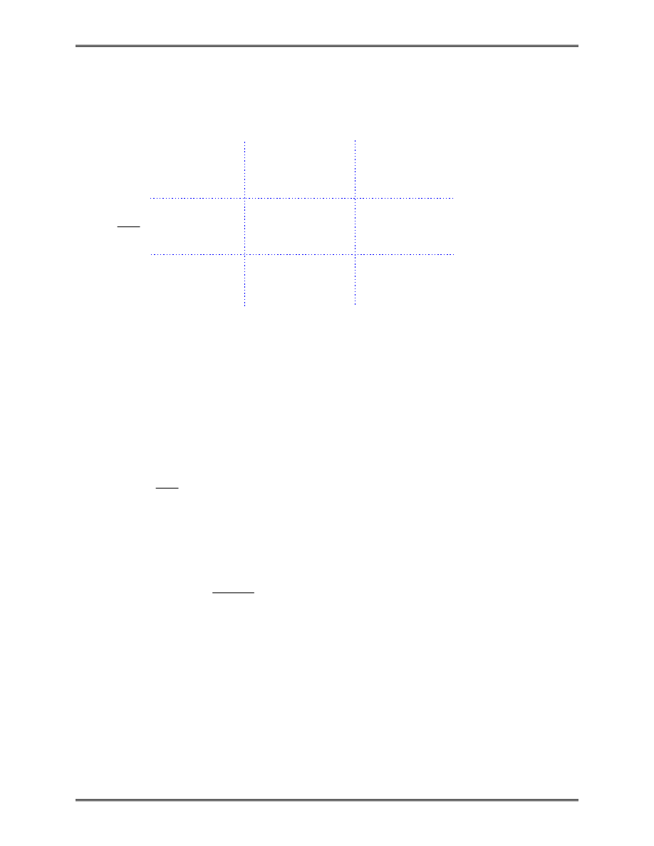
Equivalent Nodal Loads of Distributed Transverse Load
This can be verified by considering the work done by the
distributed load q.
x
i
j
q
qL/2
i
j
qL/2
L
qL
2
/12
qL
2
/12
L
q
L
L
qL
L
qL/2
qL
2
/12
Lecture Notes: Introduction to Finite Element Method
Chapter 2. Bar and Beam Elements
© 1998 Yijun Liu, University of Cincinnati
62
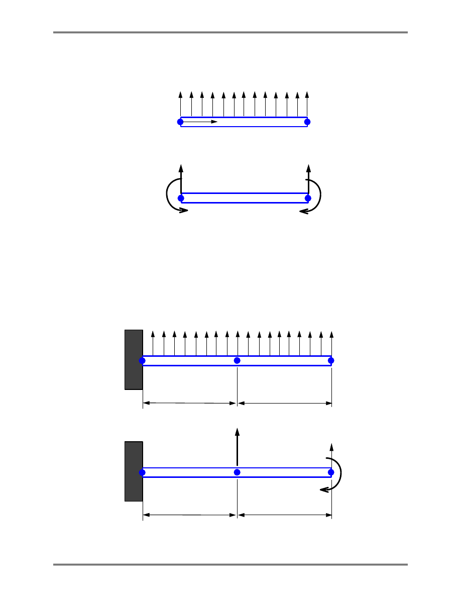
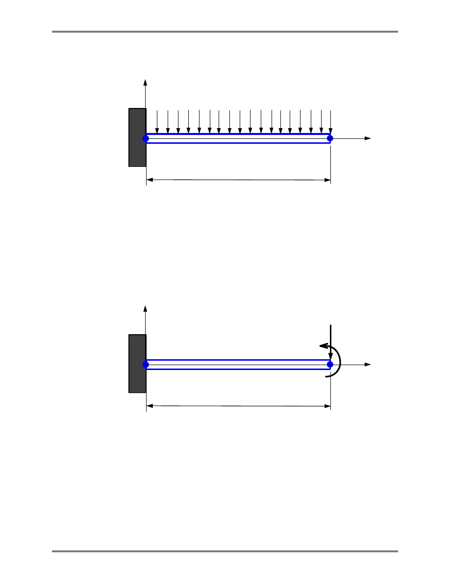
Example 2.6
Given:
A cantilever beam with distributed lateral load p as
shown above.
Find:
The deflection and rotation at the right end, the
reaction force and moment at the left end.
Solution: The work-equivalent nodal loads are shown below,
where
f
pL
m
pL
=
=
/ ,
/
2
12
2
Applying the FE equation, we have
L
x
1
2
p
E,I
y
L
x
1
2
f
E,I
y
m

Lecture Notes: Introduction to Finite Element Method
Chapter 2. Bar and Beam Elements
© 1998 Yijun Liu, University of Cincinnati
63
EI
L
L
L
L
L
L
L
L
L
L
L
L
L
v
v
F
M
F
M
Y
Y
3
2
2
2
2
1
1
2
2
1
1
2
2
12
6
12
6
6
4
6
2
12
6
12
6
6
2
6
4
−
−
−
−
−
−
=
θ
θ
Load and constraints (BC’s) are,
F
f
M
m
v
Y
2
2
1
1
0
= −
=
=
=
,
θ
Reduced equation is,
EI
L
L
L
L
v
f
m
3
2
2
2
12
6
6
4
−
−
=
−
θ
Solving this, we obtain,
v
L
EI
L f
Lm
Lf
m
pL
EI
pL
EI
2
2
2
4
3
6
2
3
3
6
8
6
θ
=
−
+
−
+
=
−
−
/
/
(A)
These nodal values are the same as the exact solution.
Note that the deflection v(x) (for 0 < x< 0) in the beam by the
FEM is, however, different from that by the exact solution. The
exact solution by the simple beam theory is a 4
th
order
polynomial of x, while the FE solution of v is only a 3
rd
order
polynomial of x.
If the equivalent moment m is ignored, we have,
v
L
EI
L f
Lf
pL
EI
pL
EI
2
2
2
4
3
6
2
3
6
4
θ
=
−
−
=
−
−
/
/
(B)

Lecture Notes: Introduction to Finite Element Method
Chapter 2. Bar and Beam Elements
© 1998 Yijun Liu, University of Cincinnati
64
The errors in (B) will decrease if more elements are used. The
equivalent moment m is often ignored in the FEM applications.
The FE solutions still converge as more elements are applied.
From the FE equation, we can calculate the reaction force
and moment as,
F
M
L
EI
L
L
L
v
pL
pL
Y
1
1
3
2
2
2
2
12
6
6
2
2
5
12
=
−
−
=
θ
/
/
where the result in (A) is used. This force vector gives the total
effective nodal forces which include the equivalent nodal forces
for the distributed lateral load p given by,
−
−
pL
pL
/
/
2
12
2
The correct reaction forces can be obtained as follows,
F
M
pL
pL
pL
pL
pL
pL
Y
1
1
2
2
2
2
5
12
2
12
2
=
−
−
−
=
/
/
/
/
/
Check the results!
Wyszukiwarka
Podobne podstrony:
Chapt 02 Lect08
Chapt 02 Lect02
Chapt 02 Lect05
Chapt 02 Lect01
Chapt 02 Lect07
Chapt 02 Lect03
Chapt 02 Lect04
Chapt 02 Lect08
Chapt 02 Lect02
Chapt 02 Lect05
Chapt 02
Wyk 02 Pneumatyczne elementy
02 OperowanieDanymiid 3913 ppt
02 Boża radość Ne MSZA ŚWIĘTAid 3583 ppt
OC 02
więcej podobnych podstron