Lecture Notes: Introduction to Finite Element Method
Chapter 2. Bar and Beam Elements
© 1998 Yijun Liu, University of Cincinnati
65
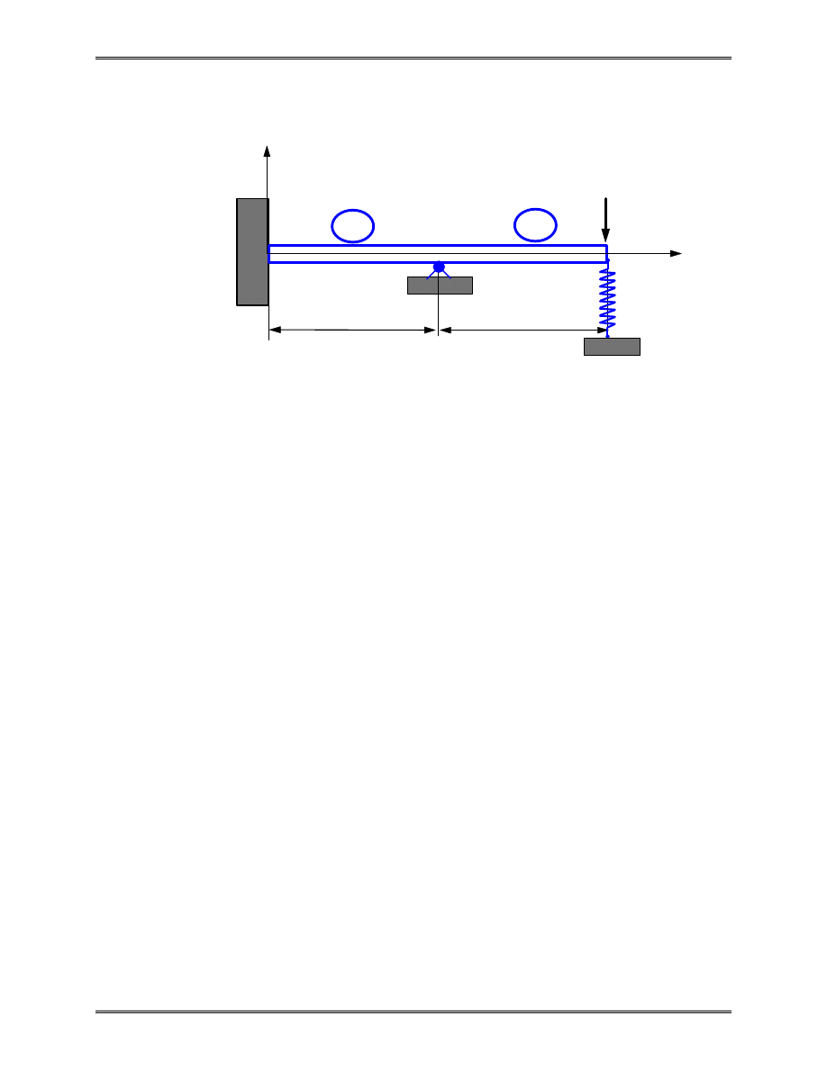
Example 2.7
Given:
P = 50 kN, k = 200 kN/m, L = 3 m,
E = 210 GPa, I = 2
×
10
-4
m
4
.
Find:
Deflections, rotations and reaction forces.
Solution:
The beam has a roller (or hinge) support at node 2 and a
spring support at node 3. We use two beam elements and one
spring element to solve this problem.
The spring stiffness matrix is given by,
v
v
k
k
k
k
s
3
4
k
=
−
−
Adding this stiffness matrix to the global FE equation (see
Example 2.5), we have
L
X
1
2
P
E,I
Y
L
3
1
2
k
4

Lecture Notes: Introduction to Finite Element Method
Chapter 2. Bar and Beam Elements
© 1998 Yijun Liu, University of Cincinnati
66
v
v
v
v
EI
L
L
L
L
L
L
L
L
L
L
k
L
L
k
Symmetry
k
v
v
v
v
F
M
F
M
F
M
F
Y
Y
Y
Y
1
1
2
2
3
3
4
3
2
2
2
2
2
1
1
2
2
3
3
4
1
1
2
2
3
3
4
12
6
12
6
0
0
4
6
2
0
0
24
0
12
6
8
6
2
12
6
4
0
0
0
0
0
θ
θ
θ
θ
θ
θ
−
−
−
−
+
−
−
=
'
'
'
in which
k
L
EI
k
'
=
3
is used to simply the notation.
We now apply the boundary conditions,
v
v
v
M
M
F
P
Y
1
1
2
4
2
3
3
0
0
=
=
=
=
=
=
= −
θ
,
,
‘Deleting’ the first three and seventh equations (rows and
columns), we have the following reduced equation,
EI
L
L
L
L
L
k
L
L
L
L
v
P
3
2
2
2
2
2
3
3
8
6
2
6
12
6
2
6
4
0
0
−
−
+
−
−
= −
'
θ
θ
Solving this equation, we obtain the deflection and rotations at
node 2 and node 3,
Lecture Notes: Introduction to Finite Element Method
Chapter 2. Bar and Beam Elements
© 1998 Yijun Liu, University of Cincinnati
67
θ
θ
2
3
3
2
12
7
3
7
9
v
PL
EI
k
L
= −
+
(
' )
The influence of the spring k is easily seen from this result.
Plugging in the given numbers, we can calculate
θ
θ
2
3
3
0 002492
0 01744
0 007475
v
=
−
−
−
.
.
.
rad
m
rad
From the global FE equation, we obtain the nodal reaction
forces as,
F
M
F
F
Y
Y
Y
1
1
2
4
69 78
69 78
116 2
3 488
=
−
−
⋅
.
.
.
.
kN
kN m
kN
kN
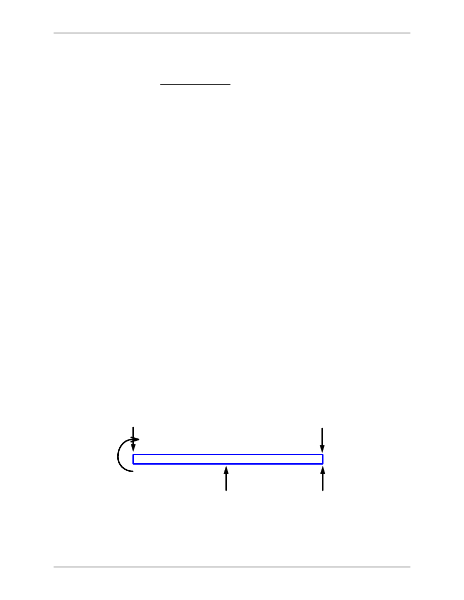
Checking the results: Draw free body diagram of the beam
1
2
50 kN
3
3.488 kN
116.2 kN
69.78 kN
69.78 kN
⋅
m
Wyszukiwarka
Podobne podstrony:
Chapt 02 Lect08
Chapt 02 Lect02
Chapt 02 Lect05
Chapt 02 Lect01
Chapt 02 Lect03
Chapt 02 Lect06
Chapt 02 Lect04
Chapt 02 Lect08
Chapt 02 Lect02
Chapt 02 Lect05
Chapt 02
Wyk 02 Pneumatyczne elementy
02 OperowanieDanymiid 3913 ppt
02 Boża radość Ne MSZA ŚWIĘTAid 3583 ppt
OC 02
więcej podobnych podstron