http://www.instructables.com/id/35mm-51-Surround-Sound-Switch-Splitter-Box/
Intro:
3.5mm 5.1 Surround Sound Switch / Splitter Box
I had a problem which needed solving.
which takes DVI and has 5.1 output using the standard PC solution of three 3.5mm jacks, coloured Green, Orange and Black. I had
hooked up my Xbox 360 via HDMI to the monitor, and the sound comes out of these (unfortunately only in Stereo since it's in Dolby Digital, but that's another story). This
would be great, however there is no similar input, meaning that I have the issue that I had to keep swapping the jacks on my subwoofer if I wanted to get any sound from
my PC or the Monitor. Having carried out much searching on the internet, I was unable to find a box that does this, and while many people seem to have similar
problems, very few people have a solution.
My first test was to simply try a headphone splitter in reverse on each individual subwoofer channel. This didnt work, since the computer's output always took presedence
over the monitor's output. It was then that I came across the following article on
- 5.1 Audio Switch. It's at this point that I decided to contact Joey Hazlett, the
owner of the site to get some information and increase my knowledge on building such a device, with a mind to do it myself. I have to say that Joey was masses of help
and the following guide wouldn't be possible without him.
So, I was going to build a splitter box which takes two 3 x 3.5mm Inputs and allows you to switch between them to one similar output.
This would be suitable for connecting two 5.1 surround sound PC cards / PC's to the same subwoofer.
Step 1:
Tools and Parts
To complete this project you will need the following tools:
Soldering Iron
Insulating tape
Drill and various sized bits
Stanley knife
Ruler
You will also need the following parts:
Speaker Wire (I already had this)
1 x
Thanks to Rapidonline.com for the parts - I really struggled to find these in the UK!
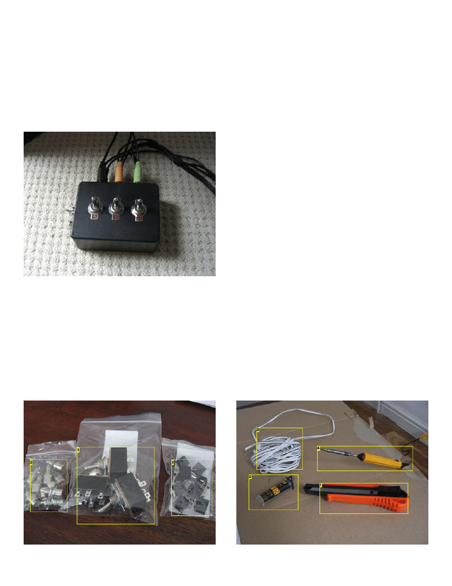
Image Notes
Image Notes
http://www.instructables.com/id/35mm-51-Surround-Sound-Switch-Splitter-Box/
1. 3 x DPDT Switches
2. Phono Connectors - you do not need this for the main bit of the build
3. 9 x 3.5mm Sockets
1. Stanley Knife
2. Solder
3. Speaker Wire
4. Soldering Iron
Image Notes
1. For reference, the sticking out side is ground, the pin closes to that is the right
channel and the other pin is the left channel
Step 2:
Designing the circuit
Initially, I wanted to do ths project with a single switch, but after not being able to find one big enough, I decided to separate the channels out. This turned out to be a
better solution anyway, since i can have two different audio sources on at the same time.
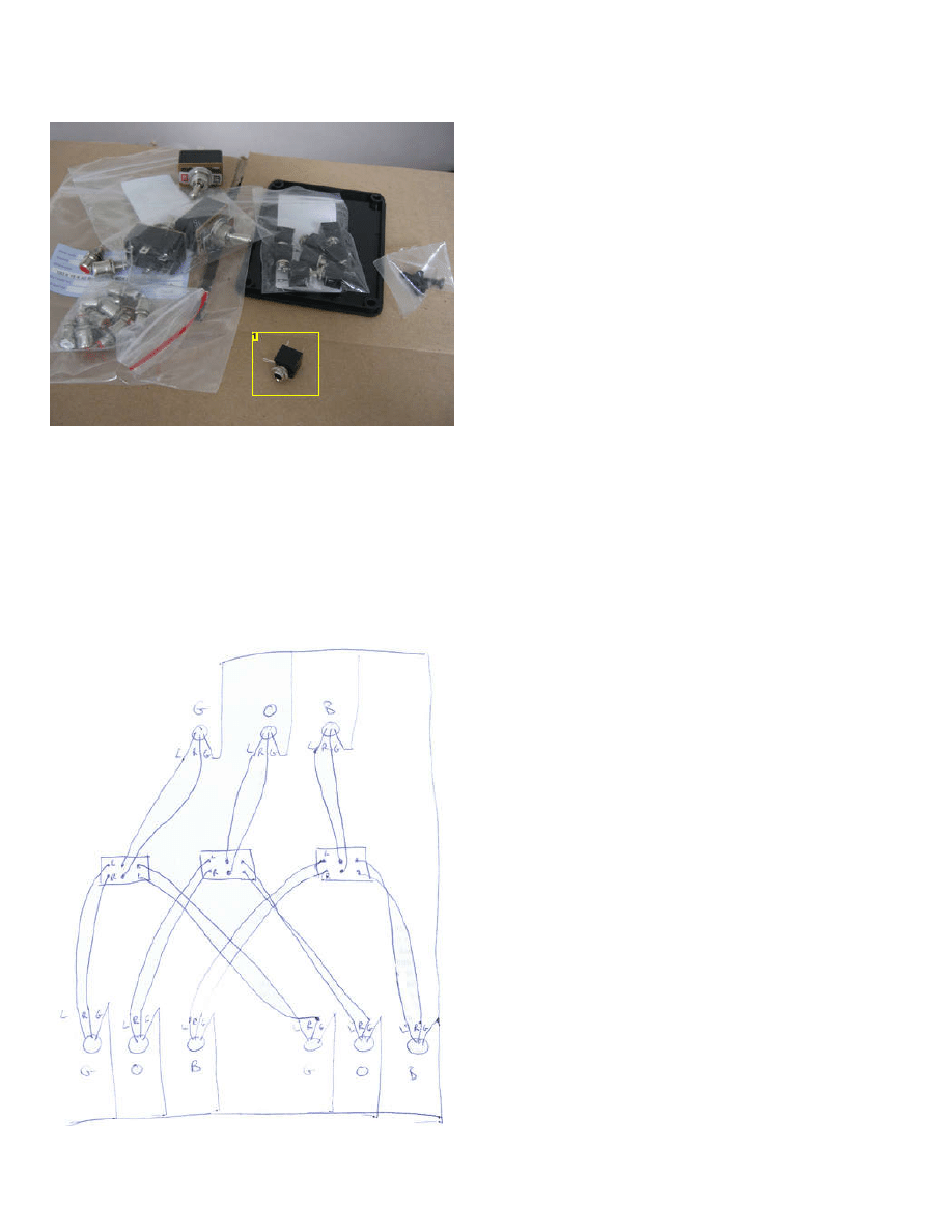
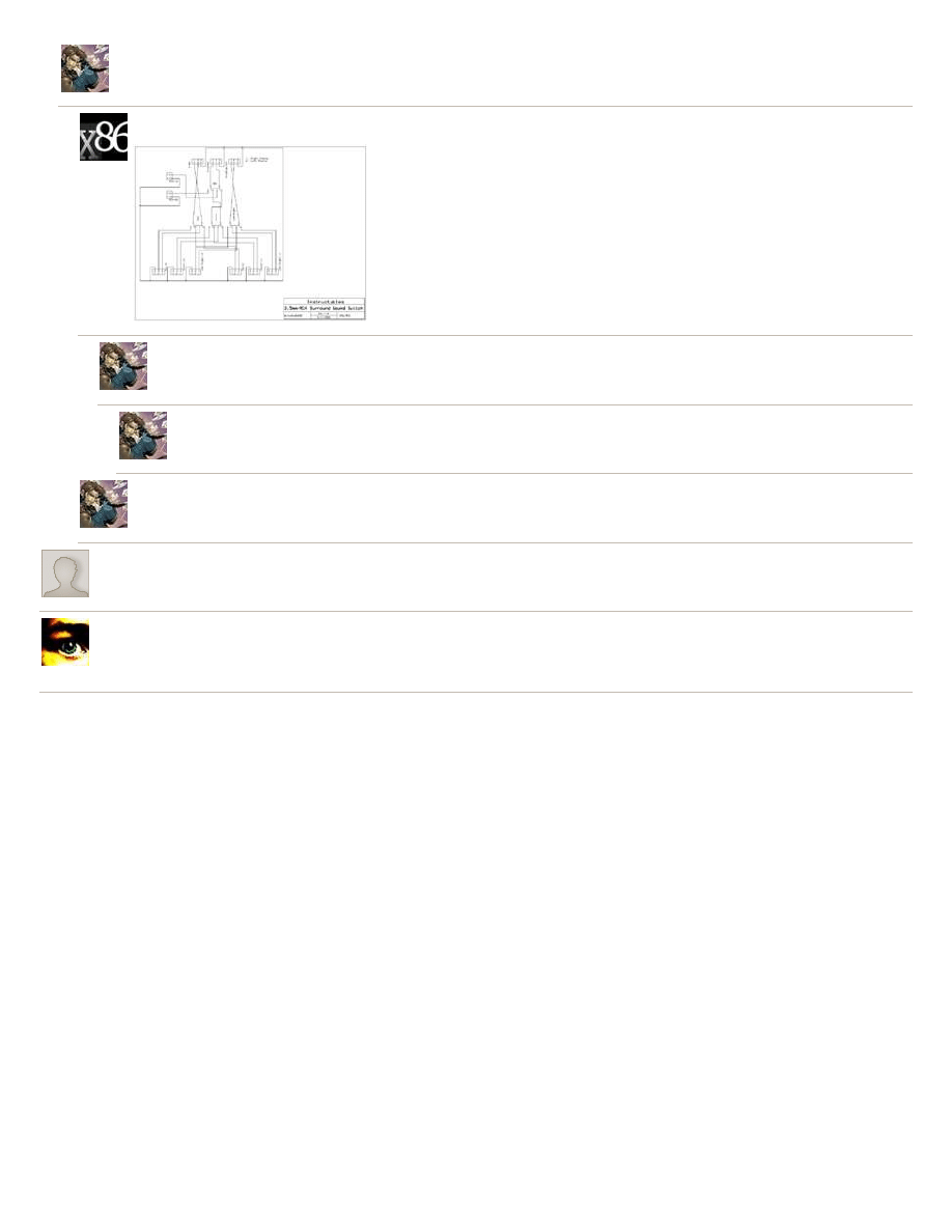
So, in the end I came up with this circuit.
G, O, B stand for Green Orange and Black, the three channels, and L, R, G stand for Left, Right and Ground. The things in the middle are three DPDT switches (Double
Pole, Double Throw), which basically allow you to take two sets of 2 contact inputs and join them to an output.
http://www.instructables.com/id/35mm-51-Surround-Sound-Switch-Splitter-Box/
Step 3:
Making the box
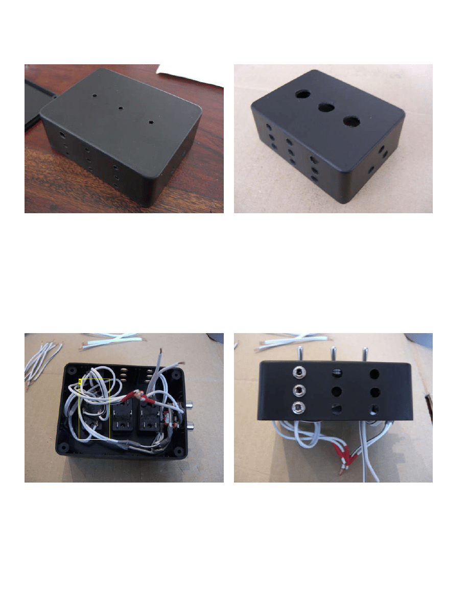
The next step is to actually drill the holes for the box.
This is fairly simple, just make sure you measure everything to lay them out neatly and start with a smaller hole and work bigger so as not to crack the plastic.
I didnt have a large enough bit for the switch holes (and if i had it wouldn't have fitted in the drill!), so I needed to drill smaller holes and file out the remainder.
Step 4:
Building the Circuit
Basically, all that happens now is that you solder everything together, fit them into the box and it works! The only thing that is tricky is making sure the wires all match up
on the correct channels.
The only place that this gets particularally difficult is on the 3.5mm socket. You need to look at this and work out which is which. On a 3.5mm jack, the tip is the left
channel, the shaft is the right, so look at the connector and you can work out which point is which.
Also, when looking at the switches, think of them as two sets of 4 points (with the middle 2 being in both set), and that each side of 3 is independent. When the switch
faces one way, you are getting those 4 points connected, and when it faces the other, the other 4. This will help you to work it out.
The final thing to remember is that every single one of the grounds needs to be joined together in one big clump! My grounds were all labelled with insulation tape so i
knew which they were.
Mostly, it's a doddle, if a little fiddly...
Image Notes
1. Lots of really neat wires ;o)
http://www.instructables.com/id/35mm-51-Surround-Sound-Switch-Splitter-Box/
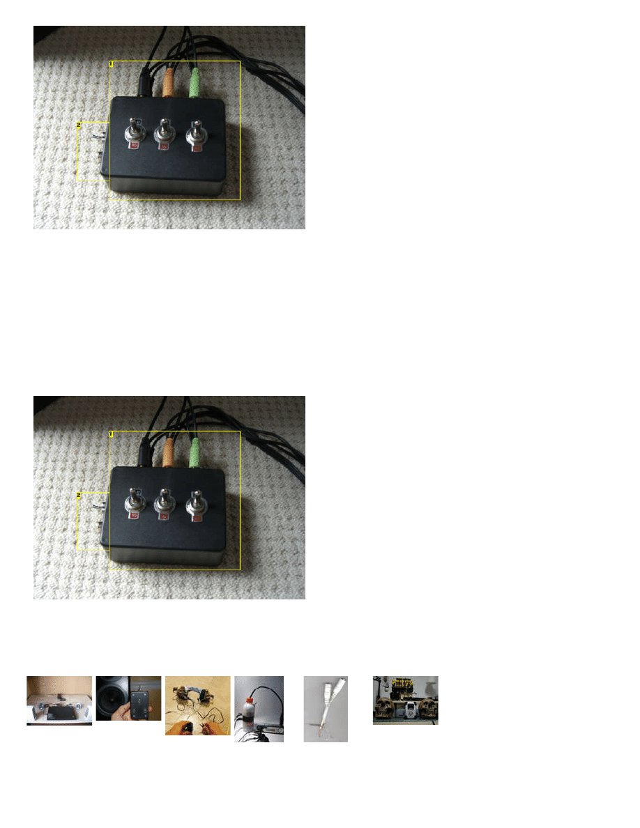
Image Notes
1. The Finished Product!
2. Optional Extra Step
Step 5:
Optional extra step
In addition to the initial premise, I also decided to take a dual phono connector in. This was to allow my Wii to connect into the same box. I also wanted this to duplicate
the front channels on the rear (with the option of turning the rear off). This in fact turned out to be the hardest part. A phono connector looks like this, with simply one wire
and the ground coming out, so after buying some phono sockets from ebay and another DPDT switch from Maplin (although I'll only use one side of it), I did the following
I had to split each phono cable into two - one for the back channel and one for the front. I then took the back channel ones (one from left (white), one from right (red)) and
attached them to one side of the DPDT switch. The middle of the switch went directly to the back channel switch on the side of input 2 - this allowed for the breaking of
the back channel for just this input. The reason I went to input 2 is because this is coming from the Monitor (i.e Xbox) and I will not be using the Wii and Xbox together.
The other two leads went directly to the switch for the front channel.
Once again, join the grounds with everything else.
Image Notes
1. The Finished Product!
2. Optional Extra Step
Related Instructables
Surround
Sound from 3.5
mm stereo
by
How to Make a
3.5mm Audio
Switch (diy)
by
by
computer
speaker
surround sound
How To Make A
Headphone
by

http://www.instructables.com/id/35mm-51-Surround-Sound-Switch-Splitter-Box/
by
Comments
40 comments
says:
Jun 14, 2011. 3:09 AM
Hi there,
I wanted to try using Y splitters first to connect my 2 computers. Would I run the risk of damaging my sound cards or the speakers if I had both systems on at
the same time? Would this setup work only if only 1 system was powered at a time? Any help is appreciated. Thanks.
says:
Jun 14, 2011. 4:07 AM
This was my first attempt, but one system always too prescience, so it didnt work. You may be luckier, but for me it was a no go...
says:
Hi, thanks so much for this instructable. I have a media center with a small media PC hooked up, and I'm thinking of getting some 5.1 speakers. However, I
also have several devices that take the old Phono switch as well as a larger computer for more serious gaming. At first I was going to ask you what
modifications I would have to make to have a 3 in 1 out. I was going to do that with this little connector: http://www.amazon.com/Logitech-Console-Adapter-
Convert-Single-Pc/dp/B0006U3ACY/
However now that I see your optional step, am I to believe that this does the same thing?? So it takes 2 real 5.1 inputs and one RCA input that just gets
cloned to the other speakers? Or are you saying that it just takes over input 2? I wouldn't ever be using two of these devices at once, however what signal
takes precedence? The two computers would almost always be hooked up and on and I'm afraid that would take over the phono input.
I guess the two questions I have are: Does this step eliminate the need for the gaming adapter? And: If I have two switching inputs that are always on, how
do I make sure I can use the phono in as well?
If this requires 3 inputs do you have any ideas on how to modify this instructable to do that?
says:
The optional extra step means it takes 2 5.1 and 2 RCA, yes, effectively taking over input two. Regarding precedence, I havent really tested it - one is my
xbox and one is my Wii, so these was never any chance they would both be on at the same time (because my monitor turns the sound off from the xbox
channel if it's not set to that video channel...
So, yes, i would say the extra step eliminated the need for the gaming adaptor, in theory. In practice, it's been a little temperamental - it works 100% fine
if i just have it going to the front two channels - trying to get it to the rear channels hasn't really worked, although i suspect this may be due to my bad
wiring!
3 inputs would be an extension of this, but you'd need a three way switch, making it significantly more complicated in wiring, and I suspect you'd need a
bigger box... (since mine is crammed as it is!)
says:
Love this instructable, and I'm having a crack at one myself using a single 6PDT switch. Two things to clarify if I may impose:
Firstly, you say "just bunch all the ground wires together". Do they actually need to go anywhere, or just solder all the ground ends into a single point?
Second, I see your switches are rated for 3A - is that required, or just what the switches can handle? I've not found a 6PDT switch yet that goes above 1A
(most of them are about 500mA), so I didn't want to go ahead and burn the switch out or something!
Thanks in advance.
says:
Hi there.
To answer your questions - nope, the grounds dont need to go anywhere at all - just bunch them up and tape over them for insulation.
As for the switches, the rating just happens to be what mine were - as far as i'm aware it shouldnt really matter what the rating is - would have thought
500mA would be fine!
Hope that helps,
Andy
says:
Thanks dude.
I don't need any special speaker wire do I. I've found some cheap lengths that have polarity marks on them, but I assume that'll just be for a
reference to ensure you wire things up properly - in our instance, I'd just need to make sure the "marked" wire connects both (for example) the left
channels.
I ask because my sound card can do polarity checks on the speakers to ensure they're wired properly, but short of miswiring something I can see
how I could reverse the polarity on the speaker output.
Thanks again

http://www.instructables.com/id/35mm-51-Surround-Sound-Switch-Splitter-Box/
says:
I used the cheapest wire possible and it's still holding up. I suspect better wire may = better sound quality, but to be honest my ears aren't good
enough to pick it up!!
says:
Jan 31, 2011. 9:24 AM
This is a great Instructable! I'm going to build a slightly modified version to switch between my computer speakers and headphones, so there's less wear
from plugging in and unplugging. (I have a laptop, but I'm using better external speakers)
says:
Dec 24, 2010. 9:41 AM
this is really cool, im making something like this right now so i don't have to unplug my speakers to plug in headphones.
(the front panel audio doesn't work right on my computer)
says:
What would be involved in making this into an actual mixer, so you could get sound from each simultaneously? That's the thing I'd *really* like to have.
Why did the PC dominate? Is it just because it was louder? Or is sound transmitted from the monitor dumped because the PC's sucking it to ground or
something?
says:
I wish I could help, but I really don't know! I think it's probably simply a power issue, but I actually don't know, and since it could be fixed for what I
wanted, I just didnt look into it further! Sorry!
says:
Jul 30, 2010. 4:13 PM
First off, I really like this idea, thanks for posting it! I've been trying to find a way to switch audio from my 5.1 Logitech speaker system between my computer
and my iPod for when I want to listen to music but don't feel like having my computer on. I'm trying to make something after your model, but since one input
is my 2-channel iPod, I don't really need another set of 3x3.5mm jacks. Would I be safe just splitting the wires from each channel of the iPod input itself and
running them to each switch? Also, have you stumbled upon a single switch since you first posted this? I'd like to avoid having three separate switches if
possible.
says:
Fraid I havent run across a single switch, no! What you'd need to do for your iPod is exactly what I did with my Wii - just run the wires to the switches for
front (and rear if you need...)
says:
Jan 13, 2010. 7:52 AM
I have just made something like this, that has one input and two outputs so i can have both my 5.1 surround speakers and my 5.1 headset plugged into the
switch box to pc and switch between the two. Someone rly needs to make these comercially they could make a killing, its so simple. Nice instructable btw
because splitters suck! switch boxes are the way forward.
says:
Awesome, I was using 3 y splitters, and thought about making something like this myself, because the splitters ruin the audio on both. Its funny i drew up
almost the exact same diagram on a napkin. Though you think someone would make a commercial product like this already...
says:
Nov 18, 2009. 8:43 AM
There is something similar that's commercially available, designed for all RCA and S-Video jacks for connecting multiple devices to your TV/amplifier...
says:
Dec 2, 2008. 10:07 AM
Too right, although it was nice to have another little project to hack away at!
says:
Aug 29, 2008. 9:19 AM
http://www.turtlebeach.com/products/cables.aspx
There are 2 options already created for this.
says:
Aug 29, 2008. 9:28 AM
Yes, and no.
Initially, i tried to use 3 headphone splitters to do the same job. The trouble is, there is clearly a more powerful signal coming from the PC even when not
in use, as it always took precedence - when connected via the splitter, whichever way, i couldnt get the monitor sound to output, even with the
soundcard disabled!
says:
Jul 24, 2009. 6:20 AM
Hey, I just had this problem and got a Surround Sound Splitter Cable and I too had the same problem you had (One channel stronger than the other)
I just put a switch inline on each of one lot of the 3 inputs so it basically shuts it off

http://www.instructables.com/id/35mm-51-Surround-Sound-Switch-Splitter-Box/
says:
what is the optional extra step for?
says:
Jun 13, 2009. 8:58 AM
It's to allow my Wii (or any phono output) to also connect via the same box, and be expanded onto all 4 speakers, rather than just the front ones.
says:
Jan 23, 2009. 3:40 PM
says:
Jan 23, 2009. 2:47 PM
BL3ND.com » Blog Archive » 5.1 Audio Switch
is
says:
First of all, thank you for the instructable, now for my question. You weren't very clear about what to do with the ground leads, i was just planning on leaving
them empty, but it would appear from your drawing that they are all connected. Is that right? I will only be making one with 2 stereo inputs, so basically just
1/3 or yours, if that matters at all. Jarrod
says:
Jan 6, 2009. 11:40 PM
Just bunch all the grounds together. That's all you need to do - just make sure they are touching! I just wrapped them in some insulating tape :)
says:
ok, thanks Jarrod
says:
wow wonderful tutorial ! Thank You. Actually who is best LCD TV or LCD monitor ? What all advantages and disadvantages for both of them ?
says:
Aug 19, 2008. 5:25 PM
Wow, this is the exact project I have been working on. I did a review on the 2709W monitor in Dell's website a few weeks back (BTW, what do you think of
the monitor :p). I just had to signup on this website to leave a comment, nicely done. I also came across Joey Hazlett's website with his 6PDT design and
feel your solution yield greater application when stereo audio is all you need.
says:
Hey mate, glad you liked the Instructable! I really like the monitor on the whole - there are a few little niggles - mostly that it doesn't decode dolby digital
5.1, so can only get stereo out of my xbox, and that it doesn't auto switch between inputs when one is turned off. Other than that, I'm very happy with it!
How about you? Have you built your audio box yet?
says:
Aug 20, 2008. 9:57 AM
I have a new niggles with my whole setup with the 2709W as well. I use a monoprice 4x2 matrix to hook everything up, and I always run into a little
problem here and there to get everything startup correctly. Overall though, I am happy with the screen and intend on keeping it. I am in the process of
getting some PCB made to complete the audio box, slowly but surely I will complete the project.
says:
Aug 11, 2008. 3:13 PM
Could you possibly post a schematic of the optional step. I think I have it worked out, but wanted to know if this is essentially how you did it.
http://www.instructables.com/id/35mm-51-Surround-Sound-Switch-Splitter-Box/
says:
Aug 11, 2008. 3:34 PM
That's not quite right - it'll work if you want to turn the phono's totally off or totally on, but wont if you only want to be able to turn the back speaker off. I'm
just off to bed, but i'll try post the schematic tomorrow...
says:
Aug 11, 2008. 5:23 PM
Fixed the schematic. I believe this is what you were trying to say...
says:
Again, not quite right - you have nothing going from the phono's to the front channel. Also, you don't want the standard inputs going into that
switch. I'll do a sketch of it this evening and scan it in...
says:
Bad news... my scanner seems to have packed in :( If i ever get it running i'll do this for you!
says:
Aug 11, 2008. 3:36 PM
Probably should have said, to do what i did and only turn the rear off, you need to split the phono before the switch, then take one of each straight to
the front connectors, and one of each via the switch
says:
Aug 10, 2008. 7:49 PM
awesome! i've been thinking about making one of these so i can switch my pc between surround headphone output, and outputting to my amp (via it's 5.1ch
inputs) but have never been bothered to work out the wiring :) now you've done it for me i'm going to make one soon :)
says:
Aug 10, 2008. 5:27 PM
I had the exact same experience with trying to find an audio contraption! I ended up having to make a switchbox because I just couldn't find one anywhere. I
would have made an Instructable, but I glued the durn thing shut and don't have the need or motivation to make another one. Maybe later... Good
documentation!
Wyszukiwarka
Podobne podstrony:
Angelo Farina Real time partitioned convolution for Ambiophonics Surround Sound
Automatic headlight switching Surround lighting coming leaving home from 2004
instrukcja obsługi VIVANCO SBX 3 3 AUTO AUTOMATIC AV SCART SWITCH BOX
51 Wypowiedzenie zmieniające
2009 06 15 21;42;51
49 51
Document (51)
51 Kodeks Etyki Sluzby Cywilnej
Conan 51 Conan Pan czarnej rzeki
Cw 10 (51) Pomiar ładunku właściwego e m elektronu
51 54
Dance, Shield Modelling of sound ®elds in enclosed spaces with absorbent room surfaces
51
Page153 Model 2491 2492 2493 Digital Switchboard meter c
picket window box
Baumer Inductive proximity switch IFFM 08P17A6 KS35L
51 54
11 2003 51 52
więcej podobnych podstron