We reserve the right to make changes in design or add improvements without incur-
ring the obligation to make such changes in equipment previously manufactured.
PARTS-SERVICE
GRAM
FF00050
September, 1996
E30-50FR
Subject: Sticking Horn Button
During normal operation, the horn button occasionally sticks in the actuated position. This will cause
the horn to remain on after the horn button is released. It can also create difficulties in calibrating and
programmmg the features of the truck.
The opening in the control handle assembly is too narrow to accommodate the width of the button. This
restricts the movement of the horn button.
The following steps should be performed to increase the width of the horn button opening in the
control handle.
Disconnect the battery and discharge the capacitor bank
Note: Discharge the capacitor bank by turning the key on after disconnecting the battery. The
display will come on and then go out, indicating the capacitor bank is discharged.
Inspect the horn button in the control handle for rubbing or chafing. Note the position of the rub-
bing. If possible, listen to the actuation of the switch. A slight clicking sound should be heard when
the switch actuates and again when the switch de-actuates. It is possible for the switch to actuate
properly but not de-actuate.
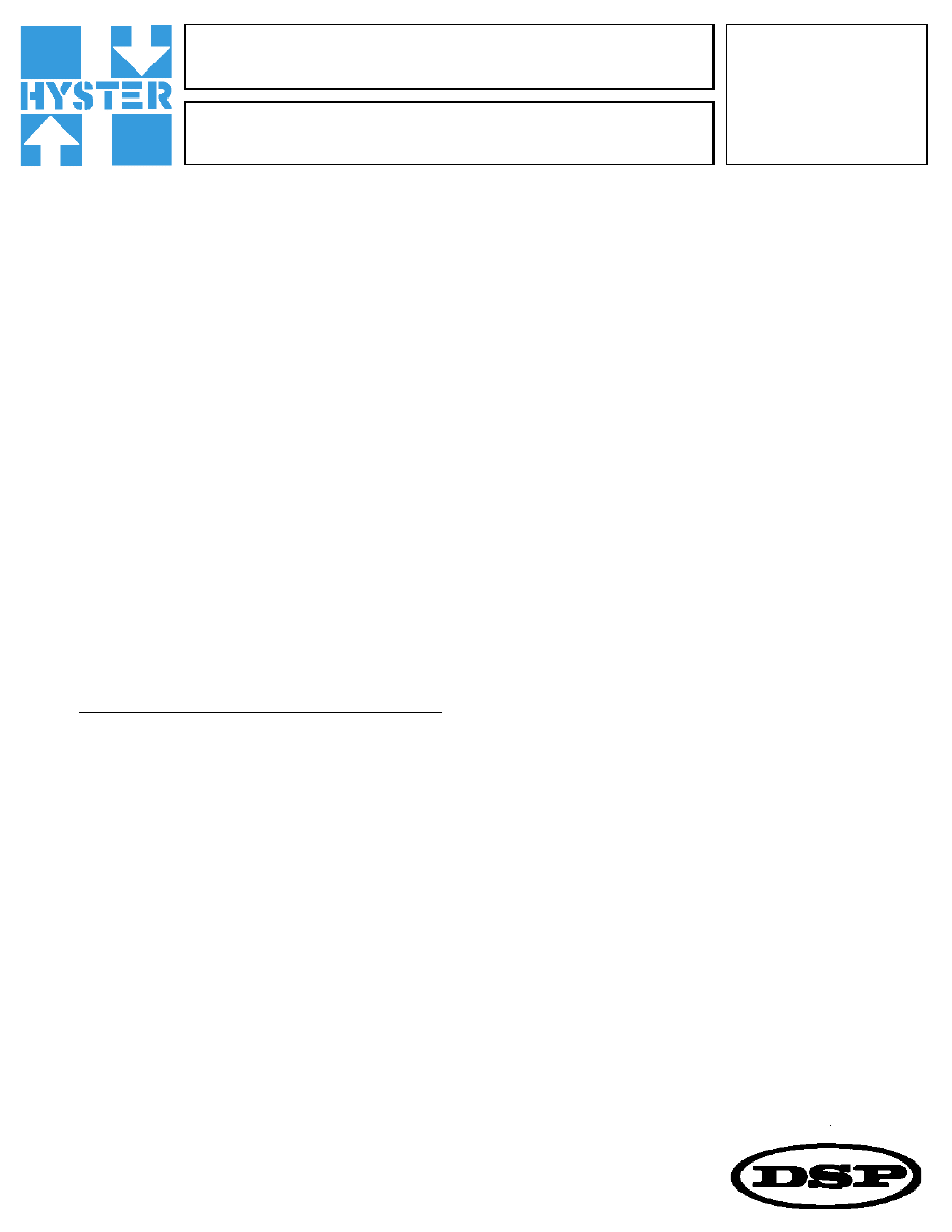
For Steps 3 through 8 refer to Figure 1 on page 2.
Using a 5/64" Allen wrench, remove the two screws (Item 1f) securinf the bezel to the top of the
control handle.
Remove the bezel (Item la) Rom the control handle.
Remove the rocker (Item lb).
Remove the keypad switch (Item 1c).
...continued
1.
2.
3.
4.
5.
6.
FF00050
Page 2
Using a pair of small needle nose pliers, carefully remove the horn button spring (Item le).
Note: Use extreme care when removing the horn button. The switch actuator on the horn switch can
be damaged if the button is not removed properly.
Carefully remove the horn button (Item ld).
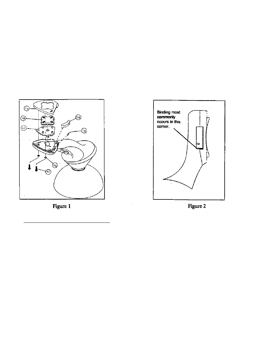
Note: The most common area where interference occurs is in the corner of the opening closest to
the horn button spring mounting post (see Figure 2).
Using a fine cut flat needle file or sharp knife, carefully remove the material interfering with the
movement of the button.
For Steps 10 through 14 refer to Figure l.
10. Install the horn button.
1 l. Install the horn button spring.
12. Install the keypad switch.
13. Install the rocker.
14. Install the bezel and secure in place with two screws.
15. Test the movement of the horn button.
16. Connect the battery.
7.
8.
9.
Wyszukiwarka
Podobne podstrony:
P27 050
2010 03, str 050 052
mat bud 050 (Kopiowanie) (Kopiowanie)
p40 050
p09 050
P28 050
p37 050
p34 050
p07 050
Koło zębate 42 L 050 2F EBMiA
P26 050
050
polNP 050 ac
050 Początek
03 2005 050 052
p02 050
p41 050
p12 050
więcej podobnych podstron