1
INTRODUCTION
GENERAL
This section has a description and the repair and adjust-
ment procedures for the different battery indicators used
on electric lift trucks.
CAUTION
Do not operate an electric lift truck with a
discharged battery. Continued operation can
damage contactors, motors and the battery.
WARNING
If the lift truck has been operated using a low
battery, check all contactors for welded contacts
BEFORE connecting a charged battery. Lift truck
operation cannot be controlled if the contacts are
welded.
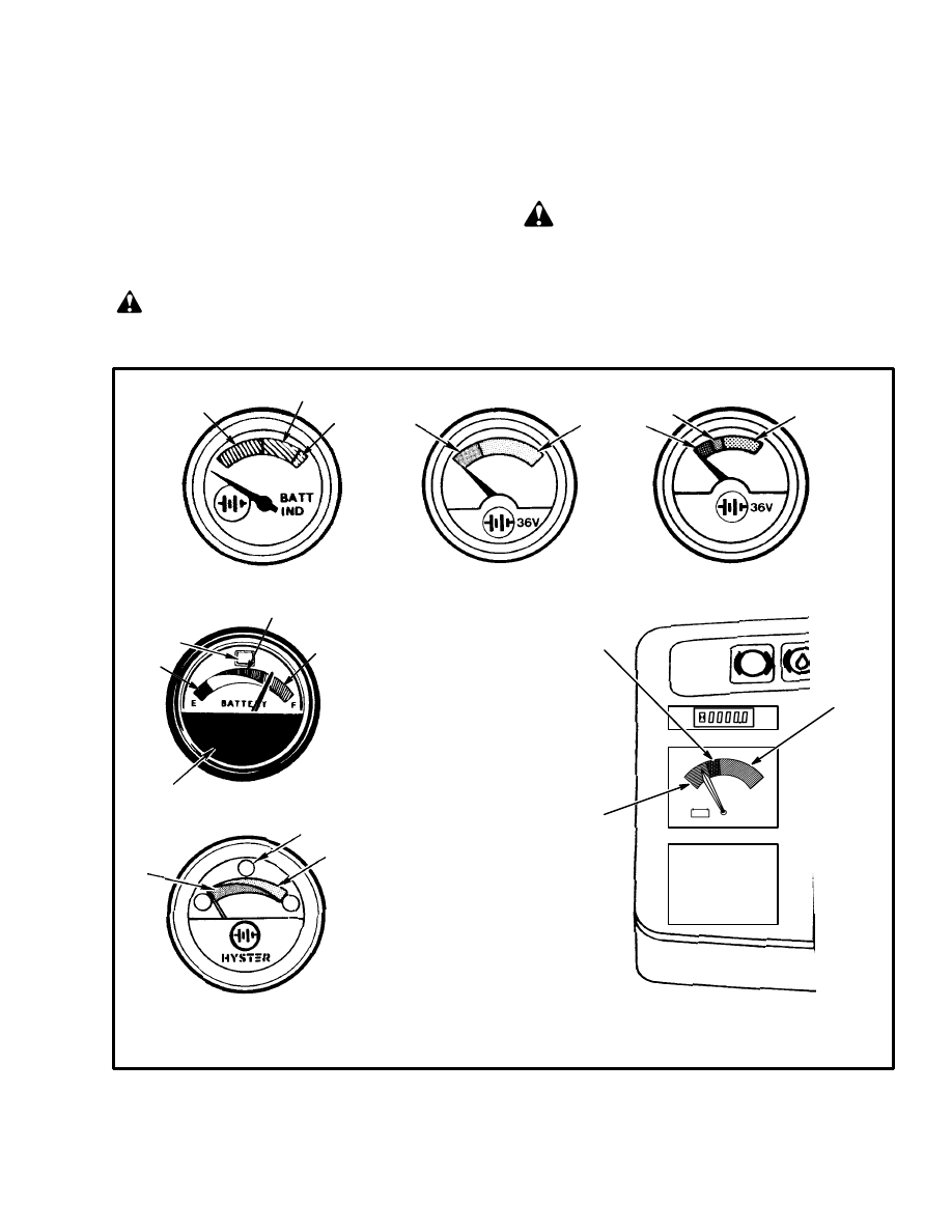
BATTERY INDICATORS WITHOUT LIFT INTERRUPT
3
1
2
FIGURE 1. BATTERY INDICATORS WITH METER MOVEMENTS
5499
1. RED BAND
2. YELLOW BAND
3. GREEN BAND
4. LIGHT (LIFT INTERRUPT
INDICATOR)
1
2
4
1
3
*LOWER METER FACE CAN BE
DIFFERENT THAN SHOWN
5499
*
4
5499
1
2
3
1
2
3
BATTERY INDICATORS WITH
LIFT INTERRUPT
1364435
1
2
3
BATTERY INDICATOR
WITHOUT LIFT INTERRUPT
A
B
C
D
E
F
2
BATTERY INDICATOR, EARLY MODELS
(WITH LIFT INTERRUPT)
BATTERY INDICATOR, LATER MODELS
(WITH LIFT INTERRUPT)
BATTERY INDICATOR
(WITHOUT LIFT INTERRUPT)
6449
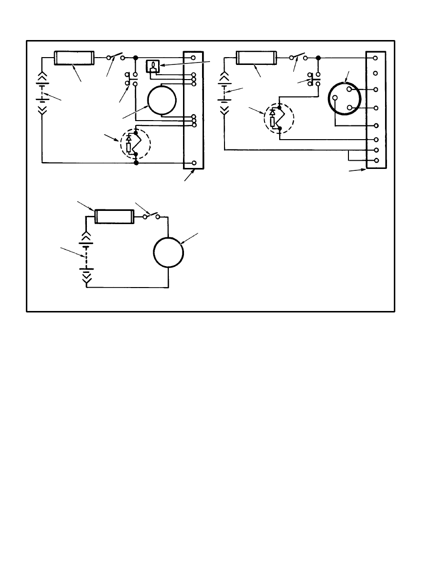
1. FUSE
2. KEY SWITCH
3. LIGHT, LIFT INTERRUPT INDICATOR
4. BATTERY INDICATOR
5. BATTERY
6. SWITCH, PUMP MOTOR
7. CONTACTOR, PUMP MOTOR
8. TERMINAL STRIP, CONTROLLER
1
2
4
5
6
7
8
1
2
4
5
6
7
8
1
2
4
5
1
2
3
4
5
6
7
8
+
–
+
–
1
2
3
4
5
6
7
8
FIGURE 2. ELECTRICAL CIRCUITS FOR BATTERY INDICATORS WITH METER MOVEMENTS
3
INDICATORS WITH METER MOVEMENTS
(See FIGURE 1. and FIGURE 2.)
The lift truck can have one of two types of battery indi-
cators. One type of indicator does NOT have Lift Inter-
rupt and is not adjustable. The other type of battery indi-
cator HAS Lift Interrupt and is adjustable for different
batteries or operating conditions. The indicator that
does not have Lift Interrupt is a voltmeter. The face of
the meter has a green and red band. Some meters also
have a yellow band between the red and green bands.
During operation, the indicator needle moves from the
green to the red band to indicate a discharged battery.
When the battery is fully charged, the needle is in the
green band.
The early (D of FIGURE 1.) battery indicator with Lift
Interrupt automatically measures the charge of the bat-
tery. A separate controller for the meter has an electronic
circuit. This circuit controls the meter movement, a
warning light (early units only) and an electronic switch
for the main hydraulic pump. The circuit can remember
the charge on the battery when the battery is discon-
nected and connected. The meter face has a band that is
red at the left end and green at the right. Some indicators
have a split area with green on top and yellow on the bot-
tom. Some other meters have a yellow band between the
red and green bands. The needle location indicates the
battery charge level. When the needle is at the edge of
the red area of the band, the warning light illuminates if
the indicator has one. At this point, the battery has ap-
proximately 5% (reserve) capacity remaining. If the re-
serve is used, the needle enters the red band and power to
the hydraulic pump motor is interrupted until the battery
is charged or replaced. Normally there is enough battery
power to move the lift truck to a battery charger or to a
place where a charged battery can be installed. When the
needle of the indicator is in the red band, the battery
3
must be charged or changed. Continued operation will
damage the battery, contactors or motors.
Another of the battery indicators WITH Lift Interrupt is
also a gauge type instrument (E of FIGURE 1.). A sepa-
rate controller for this indicator has an electronic circuit
that controls the indicator needle, a red warning light
and an electronic switch for the main hydraulic pump.
The circuit can remember the charge on the battery
when the battery is disconnected and connected. This
gauge indicator has a band that is a split area with green
on the top and red on the bottom. The needle location in-
dicates the battery charge level. When the battery has
been discharged so that the warning light illuminates,
there is still some capacity in the battery. If operation is
continued, power to the main hydraulic pump circuit is
interrupted (specific gravity is approximately 1.140).
This action prevents the operation of the main hydraulic
pump. Normally there is enough battery power to move
the lift truck to a battery charger or to a place where a
charged battery can be installed. When the warning light
illuminates, the battery must be charged or changed.
Continued operation will damage the battery, contactors
or motors.
BATTERY INDICATORS WITH LCD OR
LED DISPLAYS (See FIGURE 4.)
NOTE: The Lift Interrupt function on lift trucks that
have the EV–100ZX or the EV–T100 motor controllers,
is part of the control card. These lift trucks also have one
of two display panels. The Standard Display Panel has a
mechanical meter for a battery indicator (voltmeter).
See FIGURE 1. The Enhanced Display Panel has a bar
scale of Light Emitting Diodes (LED’s) for a battery in-
dicator. See FIGURE 4. The battery indicators dis-
cussed here do not use mechanical meters to show the
battery charge.
There are battery indicators that are parts of display pan-
els or meter faces that include other indicators. See the
section INSTRUMENT PANEL INDICATORS
AND SENDERS, 2200 SRM 143 for these other indi-
cators.
Some of these battery indicators also have the Lift Inter-
rupt function to help prevent damage to motors, contac-
tors and batteries. Lift Interrupt prevents motor opera-
tion of the main (lift) hydraulic pump when the battery
discharges to a value too low for continued operation.
Some of the battery indicators have a Liquid Crystal
Display (LCD) to show the state of charge of the battery.
Others have red, yellow and green Light Emitting
Diodes (LED’s) to show the state of charge.
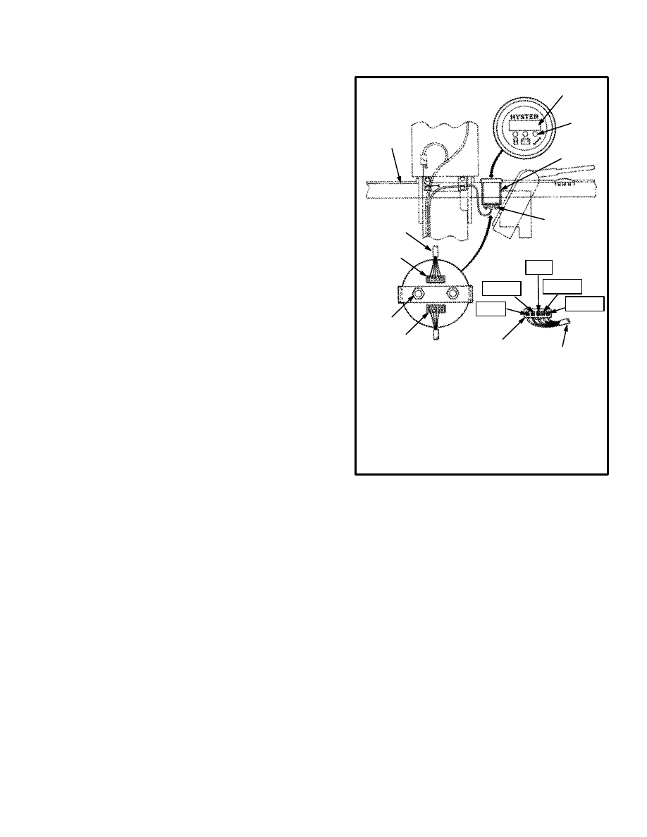
*TRACTION PLUG ONLY
12667
1. FOUR DIGIT DISPLAY
2. GREEN FUNCTION INDICATORS
3. MOUNT BRACKET
4. MOUNT NUTS
5. TRACTION PLUG
6. PUMP PLUG
7. INSTRUMENT PANEL
8. TO CONTROL CARD
BARE
GRN
BLK
NTRL
RED*
1
2
3
4
5
6
7
8
P
T
4
5
6
8
FIGURE 3. “LX” SERIES INSTRUMENT PANEL
DISPLAY BATTERY INDICATOR
Liquid Crystal Displays
These battery indicators use Liquid Crystal Displays
(LCDs) using numerical digits to show the battery
condition. This same LCD also shows other functions.
See the section INSTRUMENT PANEL INDICA-
TORS AND SENDERS, 2200 SRM 143 for the other
functions. The function that is being displayed is indi-
cated by a light at the symbol for that function. The sym-
bol for the battery indicator function is a battery.
The EV–100/200 “LX” Series motor controller can
have a display panel that includes the Battery Indicator
Function. There can also be a round (meter style) indica-
tor that includes the Battery Indicator Function. The bat-
tery indicator reading is shown on the four digit LCD
display when the function LED indicator at the battery
symbol is illuminated. See FIGURE 4. Also see
FIGURE 3.

4
There is one indicator that has a round face, green LED
function indicators for the hourmeter, service and bat-
tery indicator as well as an LCD display. See
FIGURE 3. The LCD display shows the value for each
of the three functions when that function’s LED is illu-
minated. This battery indicator is a voltmeter without
LIFT interrupt and is installed on some lift trucks with
the “LX” series of motor controller.
This battery indicator uses the traction control shunt to
measure the current during operation. This current and
battery voltage are checked at the same time for an accu-
rate reading of battery voltage with a load (during use).
This method is much more accurate than other battery
indicators used on earlier lift trucks. This method can
also make operation of the lift truck different when the
battery is low or a different battery is connected. This
method allows more usage of the battery
The battery indicator function shows the battery charge
represented by the numbers between 0 and 100. The
digital display will flash when the digital display reads
19. At a display of 9 (80% discharged), the control will
disable the lift pump circuit. After the circuit has dis-
abled the lift pump, charge or change the battery.
The control also checks the battery voltage each time a
battery is connected. The traction control will prevent
lift truck operation if the battery voltage is not correct as
set by traction function of the control card. The battery
voltage can be too high or too low. A status code of –16
(too high) or –15 (too low) will show on the instrument
panel display. A battery with the correct voltage can also
be over discharged from use or other reasons and have a
voltage that is less than the minimum rated range.
Batteries that have different amp hour ratings or are of
different ages can sometimes be used in the same lift
truck. It can be necessary to adjust traction function 14
so that the weakest battery is not damaged.
Adjustment of the battery indicator is part of the other
adjustments of the control card. These adjustments must
be made using the hand set for the “LX” Series motor
controllers. The operation of the hand set and the adjust-
ment of this and other functions is in the section
EV–100/200 LX SERIES DIAGNOSTIC MOTOR
CONTROLLER AND HAND SET, 2200 SRM 460.
CAUTION
Do NOT try to adjust the battery indicator function
or any other function without following the
procedures in section EV–100/200 LX SERIES
DIAGNOSTIC MOTOR CONTROLLER AND
HAND SET, 2200 SRM 460. Damage to the control
card or battery can occur if the hand set is not
connected and used correctly.
Light Emitting Diode Displays
These battery indicators use Light Emitting Diodes
(LED’s) of different colors to show the battery condi-
tion. There can be a round (meter style) indicator that in-
cludes the Battery Indicator Function and separate hour-
meter function. See E of FIGURE 4. There can also be
several styles of display panels that include the battery
indicator function. These display panels are used on the
“XL” and “XM” series of lift trucks with the
EV–100/200 “LX”, EV–100 “ZX” and EV–“T”100ZX
motor controllers. The control card of the “ZX” motor
controllers have the Lift Interrupt feature which can be
programmed on or off by qualified personnel using the
correct equipment.
DESCRIPTION “LX” SERIES
This battery indicator has a band of LED’s that operate
when the battery is connected. See F of FIGURE 4. If
the LED at the far right is the only LED illuminated, the
battery has a full charge. As the battery discharges, the
next LED to the left will go ON and the previous LED
will go off. When the battery needs charging, the next–
to–last LED will flash. If the last two LED’s are flashing
alternately, the battery is discharged to the point where
damage can occur. Continued operation with the LED’s
flashing can damage the battery, motors, or the contac-
tors. The system will automatically reset when a
charged battery is connected.
The display panel with the horizontal LED display is
installed on some lift trucks with the “LX” series of mo-
tor controller. This battery indicator is a scale with a se-
ries of 10 LED’s in three colors (green, yellow, red). As
the battery voltage decreases during operation, different
LED’s illuminate to indicate a discharged battery. No
more than two LED’s are illuminated at one time. When
the battery is fully charged, the two green LED’s at the
end of the scale are illuminated. When the battery dis-
charges during operation, the LED’s illuminate from
right to left (green to red). All lift trucks with this type of
5
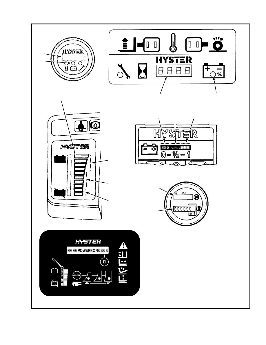
1. BATTERY INDICATOR LED DISPLAY
2. HOURMETER DISPLAY
3. RED LED’s
4. YELLOW LED’s
5. GREEN LED’s
6. LIQUID CRYSTAL DISPLAY
7. LIGHT TO INDICATE DISPLAY
IS FOR BATTERY
FIGURE 4. BATTERY INDICATORS WITH LCD OR LED DISPLAYS
11452
BATTERY INDICATORS WITH LIGHT EMITTING DIODES (LED’s)
3
4
5
12713
1340960
11508
1
2
BATTERY INDICATORS WITH LIQUID CRYSTAL DISPLAYS (LCD)
6
6
7
3
4
5
7
12667
1
A
B
C
D
E
F
1

6
warning indicator display have a lift interrupt. When the
battery is discharged to the red section of the battery dis-
charge indicator, the last two LED’s begin to flash just
before the “lift interrupt” is enabled. When the last two
LED’s are illuminated continuously, the controller for
the battery discharge indicator stops the power to the hy-
draulic pump motor. This action prevents the lift truck
from lifting. Enough battery power is normally avail-
able to move the lift truck to a battery charger or to a
place where a charged battery can be installed.
With a fully charged battery, the controller provides ap-
proximately a 5 volt signal at terminal 4 to the display.
As the battery discharges, the signal at terminal 4 de-
creases toward zero voltage. When the last red LED be-
gins to flash, the battery is approximately 70% dis-
charged (specific gravity is approximately 1.150). The
controller for the battery indicator opens the circuit to
the hydraulic pump when the battery is 80% discharged
(specific gravity is approximately 1.140).
The controller for the battery discharge indicator for this
LED display panel is in the same case as the controllers
used for other Hyster Company lift trucks, but will not
operate the same. The adjustments for the controller are
set by the manufacturer and normally are not changed. If
adjustments are required, see the REPAIRS section is
for the instructions on adjustments. The adjustment pro-
cedure for this controller is the same as the other control-
lers used in Hyster Company lift trucks.
NOTE: If the controller must be replaced, make sure
that Hyster part number 372036 is used. Controllers
with other part numbers will not operate correctly.
DESCRIPTION, “ZX” SERIES DISPLAY PANELS
The EV–100 “ZX” Series motor controller can have an
instrument panel display that includes two types of Bat-
tery Indicators. See C of FIGURE 4. The Standard Dis-
play Panel has a battery indicator without lift interrupt
(voltmeter). This meter has a green, yellow and red band
on the meter face to indicate the voltage of the battery.
The Enhanced Display Panel has a battery discharge in-
dicator with lift interrupt. This indicator shows the bat-
tery charge with a LED bar graph.
There are four green bars, four orange bars, and two red
bars. When the battery is discharged during operation,
the LED bar that is illuminated decreases sequentially
from the top green bar through the orange bars to the red
bars. When the battery is discharged to approximately
70 to 75%, the red LED bars are illuminated and the lift
interrupt function will not permit operation of the hy-
draulic motor. The battery must be charged or a charged
battery must be installed before lift truck operation can
continue. The top green bar will be illuminated when the
battery is more than 90% charged.
The battery charge indicator uses the traction control
shunt to measure the current during operation. This cur-
rent and battery voltage are checked at the same time for
an accurate reading of battery voltage with a load (dur-
ing use). This method permits better use of the battery
charge.
The controller also checks the battery voltage each time
a battery is connected. The traction control will prevent
lift truck operation if the battery voltage is not correct as
set by traction Function 15. The battery voltage can be
too high or too low. A status code of –16 (voltage too
high) or –15 (voltage too low) will indicate on the digital
display. A battery with the correct voltage can also be
deeply discharged from use or other reasons and have a
voltage that is less than the minimum rated range.
Batteries that have different ampere hour ratings or are
of different ages can sometimes be used in the same lift
truck. It can be necessary to adjust traction Function 14
of the EV–100ZX motor controller so that the weakest
battery is not damaged. Follow the procedure for adjust-
ing traction Function 14 in one of the following: the sec-
tion EV–100ZX
MOTOR CONTROLLER, 2200
SRM 557 or the section EV–T100
MOTOR CON-
TROLLER, 2200 SRM 581.
DESCRIPTION CURTIS 1215 DISPLAY PANEL
This display panel has a LED bar graph to show the bat-
tery charge that is very similar to the “ZX” display pan-
el. See D of FIGURE 4. This panel is used exclusively
with the Curtis 1215 TRACTION MOTOR CON-
TROLLER for the N30–45XMR, N25–30XMDR and
N50XMA lift trucks. See the section, Curtis
1215–9102 TRACTION MOTOR CONTROLLER
AND HAND SET, 2200 SRM 608 for additional in-
formation.
The battery indicator has a 10 bar multicolor LED dis-
play to indicate the battery charge status. The bars are
green, yellow and red. As power is used, the LED’s will
turn off, starting with green then yellow, then red. The
7
red LED second from the bottom will flash indicating a
nearly discharged battery. The bottom red Led will alter-
nately flash with the LO–Battery indicator LED (a
crossed battery symbol), indicating a discharged bat-
tery. The lift function will be disabled at this point. Con-
tinued operation with a discharged battery can damage
the battery, motor or the contactors. The battery must be
charged or a charged battery must be installed before lift
truck operation can continue. The top green bar will be
illuminated when the battery is more than 90% charged.
The controller also checks the battery voltage each time
a battery is connected. The traction control will prevent
lift truck operation if the battery voltage is not correct as
set by traction Function 15. A status code of –16 (volt-
age too high) or –15 (voltage too low) will indicate on
the digital display. The battery can have a voltage that is
too high or too low. A battery with the correct voltage
can also be deeply discharged from use or other reasons
and have a voltage that is less than the minimum of the
voltage range.
Batteries that have different ampere hour ratings or are
of different ages can sometimes be used in the same lift
truck. It can be necessary to adjust the controller to pre-
vent battery damage. Follow the adjustment procedures
in the section Curtis 1215–9102 TRACTION MO-
TOR CONTROLLER AND HAND SET, 2200 SRM
608.
CHECKS AND ADJUSTMENTS
BATTERY INDICATORS WITHOUT LIFT
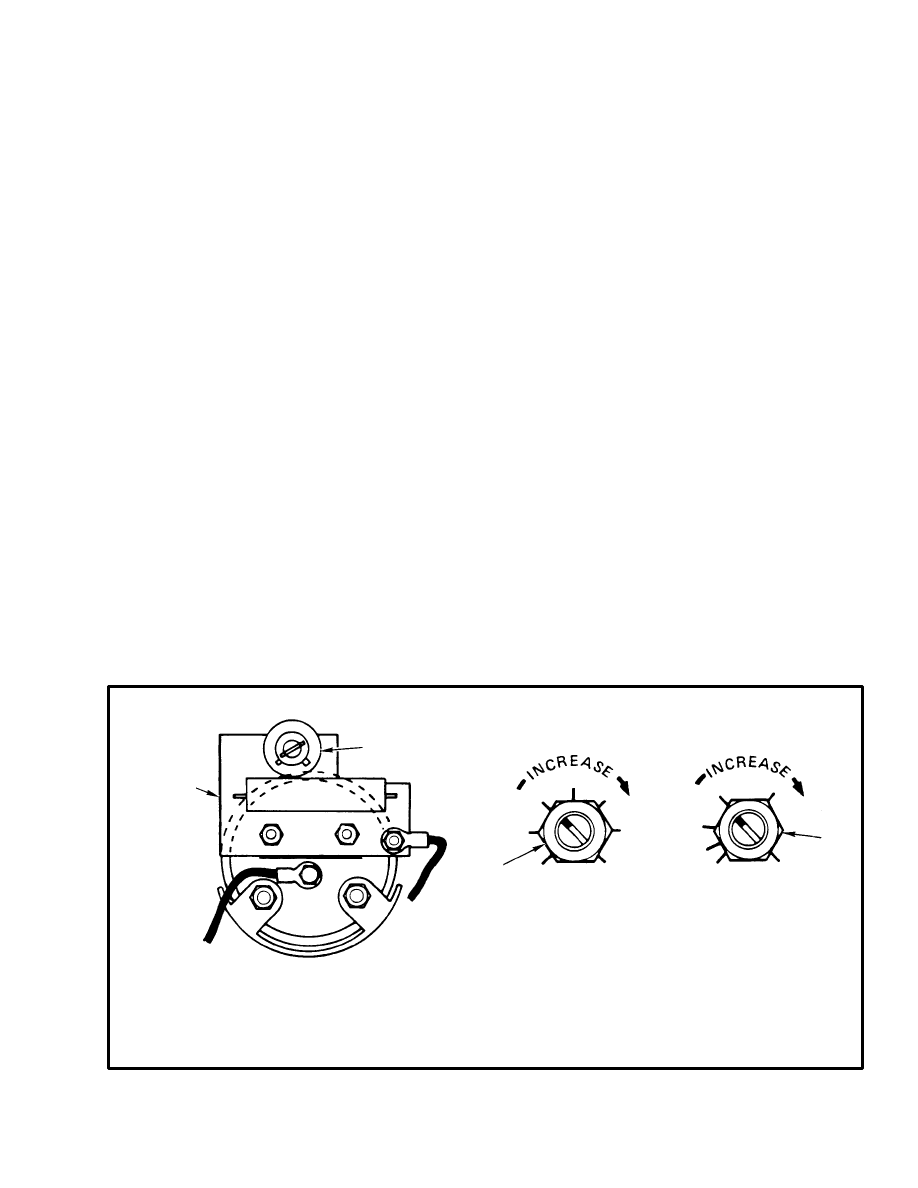
INTERRUPT, EARLY MODELS
(See FIGURE 5.)
The indicator is set at the factory for a specific gravity.
This reference voltage is for a battery discharged to a
specific gravity of approximately 1.130. This voltage
will be different for different batteries, conditions, ca-
pacity or temperature. Specific applications can cause
different settings. The setting must not be below the dis-
charge point. See the battery manufacturer for the dis-
charge point. Adjust the indicator as follows:
1. Check the specific gravity of the battery during opera-
tion of the lift truck until the battery discharges to 1.130
(or value needed).
NOTE: It is important that the battery is at the exact spe-
cific gravity for adjustment. This setting is the reference
voltage for indicator adjustment.
2. Find the screwdriver slot on the printed circuit board
for the calibration potentiometer. See FIGURE 5.
3. Operate the hydraulic system at the relief setting and
hold at this position.
*NOT USED ON ALL INDICATORS
1. PRINTED CIRCUIT BOARD
2. CALIBRATION POTENTIOMETER
3. RESET POTENTIOMETER
4. POTENTIOMETER, SPECIFIC GRAVITY ALARM
BATTERY INDICATOR
WITHOUT LIFT INTERRUPT
CONTROLLER
FOR INDICATORS WITH
LIFT INTERRUPT
RESET
LEVEL
SPECIFIC GRAVITY
ALARM
2
3
4
1*
FIGURE 5. BATTERY INDICATOR, EARLY MODELS
8
4. Adjust the calibration potentiometer (item 2) so that
the needle is in the center of the red band.
BATTERY INDICATORS WITH LIFT
INTERRUPT, EARLY MODELS
(See FIGURE 5.)
The controller for the battery indicator has two factory
set adjustments. The adjustments are made with the RE-
SET potentiometer and the SPECIFIC GRAVITY
ALARM potentiometer.
Reset Potentiometer
The RESET potentiometer determines the level to
which the battery must be charged before the indicator
indicates fully charged. The RESET potentiometer is set
at the factory to C. The RESET function operates only
when a battery has been disconnected for at least 15 sec-
onds and another battery connected. The replacement
battery must be charged to at least 90% of its capacity.
Turning the RESET potentiometer from C toward G
(clockwise) increases the voltage at which the battery is
accepted. The specific gravity of the battery must be
more than 1.245.
Turning the RESET potentiometer from C toward A de-
creases the voltage at which the battery is accepted. The
specific gravity of the battery is less than 1.245.
If a battery that is connected does not have the correct
specific gravity, the indicator will remain in its original
position.
Specific Gravity Alarm
The SPECIFIC GRAVITY ALARM potentiometer de-
termines the level at which the LIFT interrupt function
occurs. The potentiometer is set at the factory to N. The
N setting is equal to 1.73 volts per cell.
Turning the SPECIFIC GRAVITY ALARM potenti-
ometer from N toward K lets the battery discharge
MORE before LIFT interrupt occurs.
Turning the SPECIFIC GRAVITY ALARM potenti-
ometer from N toward P lets the battery discharge LESS
before LIFT interrupt occurs.
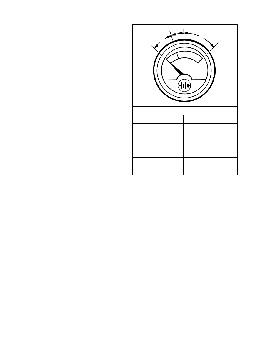
TYPE
VOLTAGE RANGE
A
B
C
12V
24V
36V
48V
72V
80V
8.5 VOLTS 10 VOLTS
13 VOLTS
17 VOLTS
20 VOLTS
26 VOLTS
25 VOLTS
30 VOLTS
40 VOLTS
34 VOLTS
40 VOLTS
52 VOLTS
51 VOLTS
60 VOLTS
78 VOLTS
57 VOLTS
67 VOLTS
87 VOLTS
11508
FIGURE 6. BATTERY INDICATOR,
LATER MODELS
A
B
C
36V
BATTERY INDICATORS WITHOUT LIFT
INTERRUPT, LATER MODELS
(See FIGURE 6.)
There is no adjustment for these indicators. The voltage
range, however, can be checked. Check the voltage set-
tings as shown in FIGURE 6. When the hydraulic sys-
tem is at the relief setting, the indicator is set to indicate a
specific gravity of 1.150. At this time the needle is in the
middle of the red band. Replace the indicator if it does
not operate correctly.
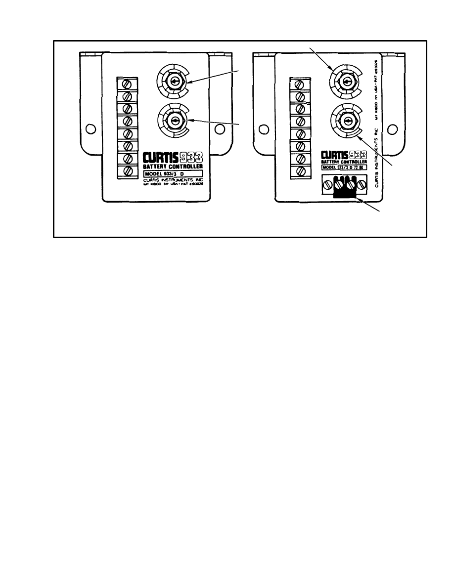
BATTERY INDICATORS WITH LIFT
INTERRUPT, LATER MODELS
(See FIGURE 7.)
The following procedures for the battery indicator apply
to both the gauge type LED indicator and the LED dis-
play indicator shown as
E
and
F
in FIGURE 4.
The controller for the battery indicators has two factory
set adjustments. The adjustments are made with the RE-
SET potentiometer and the DISCHARGE potentiome-
ter.
9
11507
1. RESET POTENTIOMETER
2. DISCHARGE POTENTIOMETER
3. JUMPER (REMOVED FOR
80 VOLT OPERATION)
DISCHARGE
DISCHARGE
A
B
C
D
E
A
B
C
D
E
K
L
M
N
O
P
K
L
M
N
O
P
1
2
3
4
5
6
7
8
1
2
3
4
5
6
7
8
36/48 VOLT
72/80 VOLT
1
1
2
2
3
FIGURE 7. BATTERY INDICATOR CONTROLLER, LATER MODELS
Reset Potentiometer
The RESET potentiometer determines the level to
which the battery must be charged before the indicator
indicates fully charged. The RESET potentiometer is set
at the factory to C. The RESET function operates only
when a battery has been disconnected for at least 15 sec-
onds and another battery connected. The replacement
battery must be charged to at least 90% of its capacity.
The RESET potentiometer increases the voltage at
which the battery is accepted when turned from C to-
ward G (clockwise). The specific gravity of the battery
must be more than 1.245.
The RESET potentiometer decreases the voltage at
which the battery is accepted when turned from C to-
ward A . The specific gravity of the battery is less than
1.245.
If a battery that is connected does not have the correct
specific gravity, the indicator will remain in its original
position.
Discharge Potentiometer
The DISCHARGE potentiometer determines the level
at which the LIFT interrupt function occurs. The poten-
tiometer is set at the factory to N. The N setting is equal
to 1.73 volts per cell.
Turning the DISCHARGE potentiometer from N to-
ward K lets the battery discharge MORE before LIFT
interrupt occurs.
Turning the DISCHARGE potentiometer from N to-
ward P lets the battery discharge LESS before LIFT in-
terrupt occurs.
LED DISPLAY WITH LIFT INTERRUPT
NOTE: If battery negative and battery positive are not
connected, the display will not operate.
To check the LED’s of the display (
F
in FIGURE 4.),
connect battery negative to terminal 13B, battery posi-
tive to terminal to 71 then connect two volts to terminal
72. The second yellow LED will illuminate. Connect
four volts to terminal 72. The second green LED will il-
luminate. With zero volts or an open at wire 72, the first
red LED will flash.
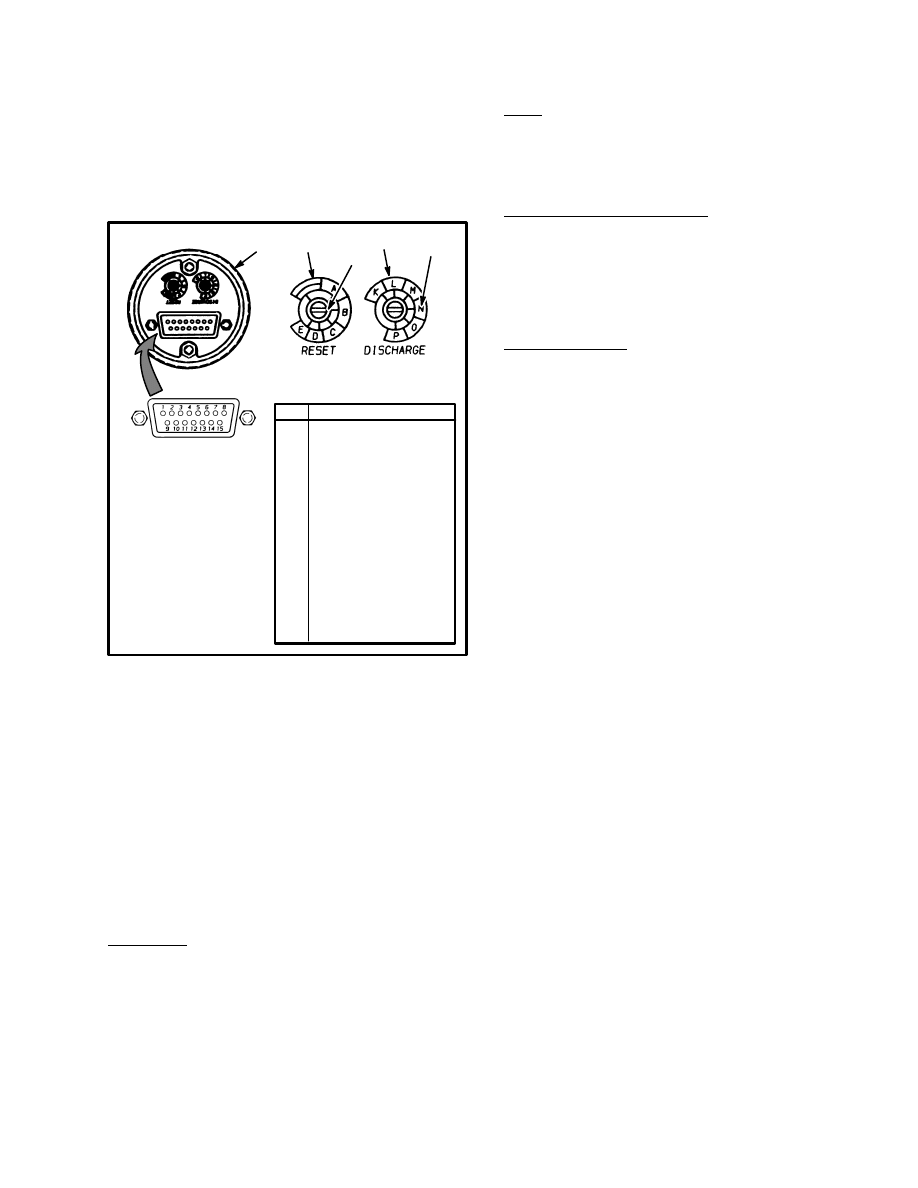
CHECKING CURTIS 933–1 METER
(
See FIGURE 4. and FIGURE 8.)
NOTE: This meter has several functions and internal
electronic circuits. See
A
of FIGURE 4. To make sure
the meter is correctly connected and operating correctly,
it is necessary to do the following checks. It is ONLY
necessary to do these checks IF THE METER OPERA-
TION IS NOT CORRECT when the adjustments are
correctly set. Make sure RESET is set to B and DIS-

10
CHARGE is set to N. Also make sure that there is NO
jumper installed at the 15 pin meter connector for 48 volt
units. There MUST be a jumper wire connected be-
tween pins 15 and 4 for 36 volt units.
It is necessary to remove the meter assembly from the
display panel to do most of the following checks. Re-
move the display panel and meter assembly as described
earlier in “Replace A Display Panel” of this section.
Hold or fasten the meter and display panel so that dam-
age does not occur to the devices or electrical connec-
tions. Connect the 15 pin connector to the back of the
meter. Connect the 18 pin connector to the back of the
display panel.
Access to the connector pins is at the back of the 15 pin
connector. The front view of the connector is shown in
FIGURE 8. Make sure the voltmeter probes are touch-
ing the correct connector pins.
Reset Check
This check will find out if the meter will reset to “Full”
after a charged battery is connected. Two different
checks can be used; Open Circuit (used with a partially
charged battery) or High Voltage (used with a fully
charged battery). Make sure the meter “RESET” adjust-
ment is set to “B” before doing either check. See
FIGURE 8.
CAUTION
Make sure the meter probes do not damage the
connector pins or other components. Make sure that
the meter probes touch ONLY the correct connector
pins.
Open Circuit
Disconnect the battery at the battery connector. Then,
connect the battery again. Measure the voltage between
pins 1 and 8 using a digital voltmeter. This voltage must
be 2.09 volts minimum per cell.
Example – 36V battery: 18 cell truck battery X 2.09
volts
= 37.62 volts minimum
Example – 48V battery: 24 cell truck battery X 2.09
volts
= 50.16 volts minimum
If the voltage is less than the minimum, the meter must
NOT reset. Do the check again using a battery with a
higher charge. If the voltage measured is more than the
minimum voltage and the meter will not reset, the meter
has a malfunction.
If the voltage is less than the minimum and the meter
does reset to “Full”, the internal battery (memory bat-
tery) of the meter can be discharged. The meter will still
show a correct discharge condition IF a charged battery
is connected and is not disconnected during the life of
that battery’s charge.
NOTE: New meters have a “Full” reading in their me-
mories. The first connection to a battery will always
show a “Full” charge. After the first connection, the me-
ter will indicate normally according to the battery that is
connected.
High Voltage
The meter must reset to “Full” if the voltage between
pins 1 and 8 is 2.35 volts per cell for six minutes or more
continuously.
Example – 36V battery: 18 cell truck battery X 2.35
volts
= 42.3 volts minimum
Example – 48V battery: 24 cell truck battery X 2.35
volts
= 56.4 volts minimum
The voltage must be above the minimum voltage contin-
uously for at least six minutes. If the meter will not reset
to “Full”, the meter has a malfunction.
Discharge Check
This check will find out if the meter correctly shows the
discharge of the battery. The meter checks the charge
condition of the battery when the battery is supplying
power (in use). It takes a minimum of 30 minutes for the
meter to change from “Full” to “Empty”. Connect a bat-
tery that has less than the minimum voltage shown in the
example. Operate the tilt circuit to use power from the
battery.
The voltage between pins 1 and 8 must be less than 2.0
volts per cell to make the meter indicate “empty”. Check
that the voltage is less than 2.0 volts per cell.
Example – 36V battery: 18 cell truck battery X 2.0 volts
= 36.0 volts maximum
11
Example – 48V battery: 24 cell truck battery X 2.0 volts
= 56.0 volts maximum
If the voltage is less than the maximum voltage for 30
minutes and the meter does not indicate “Empty”, the
meter has a malfunction.
1. BACK OF METER
2. RESET
ADJUSTMENT
3. DISCHARGE
ADJUSTMENT
4. SLOT
15 PIN CONNECTOR*
(circuit board to meter)
1
Battery Positive (B+)
2
Key Switch
3
No Connection
4
Jumper from #15
5
No Connection
6
Lockout (+)
7
Lockout (–)
8
Battery Negative (–)
9–11 Hourmeter
12
No Connection
13
No Connection
14
No Connection
15
Jumper to #4 for 36
or 72 volt operation
No Jumper for 12,
48 or 80 volt operation
PIN
FUNCTION
FIGURE 8. CURTIS 933–1 METER RESET AND
DISCHARGE ADJUSTMENTS
1
518966600
3
2
4
4
* 15 PIN CONNECTOR
AND WIRES FOR THE
METER CONNECTOR
ARE PART OF THE CIR-
CUIT BOARD OF THE
DISPLAY PANEL.
518966600
Lockout Check
This check will find out if the lockout function is cor-
rect. Lockout prevents operation of the lift circuit when
a battery is discharged too far. Lockout will not occur
until the two left LED’s (Light Emitting Diodes) illumi-
nate alternately. A short–circuit between pins 6 and 7 of
the 15 pin connector is the correct condition for a
charged battery. There must be an open circuit between
pins 6 and 7 during lockout.
No Lockout
If the lift circuit will still operate when the two left
LED’s illuminate alternately, disconnect the battery
connector. Disconnect the 15 pin connector from the
back of the meter. Use an ohmmeter to check for a short–
circuit between pins 6 and 7 at the display panel half of
the 15 pin connector. Make sure to measure between the
correct pins. The connector shown in FIGURE 8. is the
meter half of the connector. If there is a short circuit, the
display panel or truck wiring has a short circuit. If there
is no short–circuit, the meter must have a malfunction
causing a short–circuit.
Lockout With Charged Battery
If the lift circuit will not operate even when the two left
LED’s are NOT illuminated alternately, check for a
short–circuit between pins 6 and 7. If there is NO short–
circuit, the meter has a malfunction.
Lockout Too Soon
Check for less than a 1% drop in battery voltage at the
meter. Use a digital voltmeter to check the voltage be-
tween pin 1 (–) of the 15 pin connector and the positive
terminal of the battery. Operate the tilt system and re-
cord the voltage. Check the voltage between pin 8 (+) of
the 15 pin connector and the negative terminal of the
battery. Operate the tilt system and record the voltage.
Add the two recorded voltage readings. Check the volt-
age between the battery terminals. The sum of the re-
corded voltages MUST be less than 1% of the measured
battery voltage. If the battery voltage is 38 volts the re-
corded voltage must be less than 0.38 volt.
LED’s Do Not Illuminate
The discharge LED’s are illuminated by voltage through
the key switch at pin 2. Check for truck voltage between
pin 2 (+) and pin 8 with the key switch ON and the bat-
tery connected. If there is truck voltage and the LED’s
are not illuminated, the meter has a malfunction.
Hourmeter Check
The LCD (Liquid Crystal Display) of the hourmeter will
illuminate when there is power at pins 1 and 8. Use a dig-
ital voltmeter to check for voltage between pins 1 (+)
and 8. If there is truck voltage, and the LCD is not illumi-
nated, the meter has a malfunction.
Hour Glass Icon
The icon flashes when the hourmeter is operating. Make
sure the key is ON and the battery is connected. Check
for truck voltage between pin 1 (+) and 8 and between
pin 2 (+) and 8. There must also be truck voltage be-
tween pins 9, 10 or 11 and pin 8 (–). If the icon is not
flashing, the meter has a malfunction.
12
Install the meter and display panel as described in “Re-
place A Display Panel” of this section.
ADJUSTMENT OF CURTIS 933–1 METER
(See FIGURE 8.)
There are two adjustments for the Curtis 933–1 meter.
The adjustments are made on the back of the meter.
There is one adjustment screw for setting the reset level
and one adjustment screw for setting the discharge level.
Adjust the Curtis 933–1 meter as follows:
1. Disconnect the battery and remove the key from the
key switch.
2. Look at the back of the Curtis meter. Use a screwdriv-
er to rotate both adjustment screws of the meter anti–
clockwise against the stop.
3. The slot in each adjustment screw will be aligned near
the first letter. Use the screwdriver to turn the RESET
adjustment screw so that the slot is aligned near the cen-
ter of area B. See FIGURE 8.
4. Use the screwdriver to turn the DISCHARGE adjust-
ment screw so that the slot is aligned near the center of
area N.
CHECKING CURTIS 1215 BATTERY
INDICATOR
(See FIGURE 4. and FIGURE 10.)
NOTE: The Curtis 1215 Battery Indicator is part of the
display panel for the N30–45XMR, N25–30XMDR and
N50XMA lift trucks. See
D
of FIGURE 4. A Program-
mer Hand Set is available for checking and setting the
motor controller and display panel, but the following
procedure uses a digital volt ohmmeter. See the follow-
ing SERVICE MANUAL sections for more informa-
tion, troubleshooting and repair of the parts of the dis-
play panel:
1215–9102 TRACTION MOTOR CONTROLLER
AND HAND SET, 2200 SRM 608
ELECTRICAL SYSTEM, 2200 SRM 609
INSTRUMENT PANEL INDICATORS AND
SENDERS, 2200 SRM 143
NOTE: If the display panel is blank (no LCD display or
LED’s) with the key in the ON position and the main
contactor energized, there is a major malfunction. See
the section ELECTRICAL SYSTEM, 2200 SRM 609
of your SERVICE MANUAL for additional informa-
tion.
CAUTION
Only use a digital volt ohmmeter during this test
procedure. Use of other test equipment can damage
the internal components of the display panel and/or
traction motor controller
NOTE: Do not disconnect the wire harness at the dis-
play panel or the motor controller. Voltage checks must
be done with all connections in place.
X-15A JUMPER ASSEMBLY
USED 24 VOLT TRUCKS ONLY
DISPLAY WIRE HARNESS
TO DISPLAY
X-15 CONNECTOR
X-6
X-4
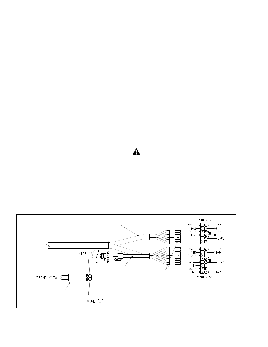
FIGURE 9. CURTIS 1215 DISPLAY PANEL CONNECTIONS AND WIRE LOCATIONS
13
Check the lift interrupt signal at the connector on the
back of the display panel. See FIGURE 9. Wire 85 car-
ries the lift interrupt signal from the display panel to the
control card of the motor controller. Normally, this sig-
nal is low (less than +5.0 volts) when the bottom red
LED is not flashing. When this LED is flashing (Lift In-
terrupt), the voltage at wire 85 will be high (greater than
+10 volts).
If the lift pump will not operate when the bottom red
LED is not flashing, you can bypass the lift interrupt
function of the display. Connect a jumper wire from bat-
tery negative to the wire 85 pin (7) of the X–6 connector
shown in FIGURE 9.
If the lift circuit still does not operate, disconnect the
battery, remove the jumper and check the continuity of
wire 85. Check from pin 7 of the X–6 connector to the J1
connector of the control card of the motor controller. See
the section ELECTRICAL SYSTEM, 2200 SRM 609
of the SERVICE MANUAL for your lift truck. If there
is continuity between the connectors pins,wire 85 is
good. Check the status codes and the motor controller as
described in 2200 SRM 609.
If lift interrupt will not prevent lift pump operation when
the bottom red LED is flashing, wire 85 can have a short
circuit to battery negative or another wire. This short–
circuit will prevent the +10 volt signal from getting to
the control card of the motor controller. If wire 85 does
not have a short–circuit, check the status codes and the
motor controller as described in 2200 SRM 609.
ADJUSTING CURTIS 1215 BATTERY
INDICATOR
(See FIGURE 4. and FIGURE 10.)
The display panel (
D
of FIGURE 4.) has two adjust-
ment pots. The pots are located on the back of the assem-
bly between the connectors. See FIGURE 10. Lift
trucks are shipped from the factory with the pots ad-
justed as follows:
RESET
“B”
DISCHARGE
“L”
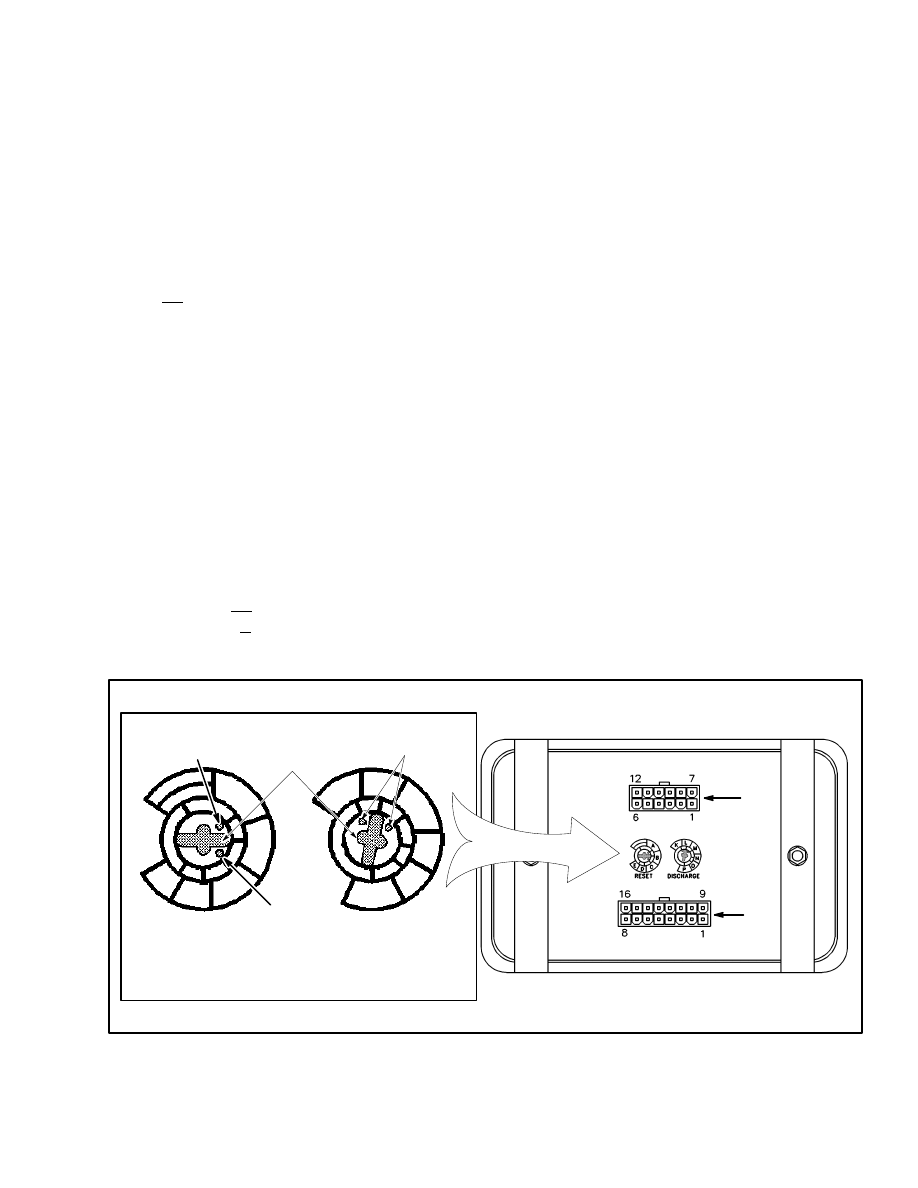
Adjustment is performed by inserting a small screw-
driver through the access hole in the rear of the display
and into the long slot of the adjustment screw. See
FIGURE 10. Rotate the screwdriver fully clockwise to
align the blade with E (reset pot) or P (discharge pot).
Rotate the pot counterclockwise to the desired setting.
Dots on one end of the screwdriver slot indicate which
end should be aligned with the appropriate setting.
SCREWDRIVER
SLOT
DOT
DOT
DOT
EXPLODED VIEW
RESET
DISCHARGE
E
D
A
B
C
K
L
M
N
O
P
X-6
X-4
FIGURE 10. BATTERY INDICATOR ADJUSTMENT

14
TABLE 1. BATTERY INDICATOR RESET
ADJUSTMENT
Reset Pot Position
Approximate Average
Volts per Cell Required
for Reset
–
2.00
A
2.06
B
2.09
C
2.12
D
2.15
E
2.18
The shaded row in the table indicates the factory setting.
The RESET potentiometer determines the level to
which the battery must be charged before the indicator
will reset to display a charged battery. The RESET po-
tentiometer is set at the factory to B. Batteries with open
circuit voltages greater than 2.09 volts per cell will
cause the battery indicator to read fully charged. The
RESET function operates only when a battery has been
disconnected for at least 15 seconds and another battery
connected. The replacement battery must be charged to
at least 90% of its capacity.
The RESET potentiometer increases the voltage at
which the battery is accepted when turned from B to-
ward E (clockwise). The specific gravity of the battery
must be more than 1.245.
The RESET potentiometer decreases the voltage at
which the battery is accepted (indicator resets to display
a charged battery) when turned from B toward A. The
specific gravity of the battery is less than 1.245. See
TABLE 1. for alternate settings.
If a battery that is connected does not have the correct
specific gravity, the battery indicator will remain in its
original position.
The DISCHARGE potentiometer determines the level
at which the LIFT interrupt function occurs. The poten-
tiometer is set at the factory to L. The L setting is equal to
1.63 volts per cell.
Turning the DISCHARGE potentiometer from L to-
ward K lets the battery discharge MORE before LIFT
interrupt occurs.
Turning the DISCHARGE potentiometer from L to-
ward P lets the battery discharge LESS before LIFT in-
terrupt occurs. See TABLE 2. for alternate settings.
TABLE 2. BATTERY INDICATOR DISCHARGE
ADJUSTMENT
Discharge Pot Position
Approximate Average
Volts per Cell at Lift
Interrupt
K
1.56
L
1.63
M
1.68
N
1.73
O
1.78
P
1.82
The shaded row in the table indicates the factory setting.
Voltage Selection
Voltage selection (24 or 36 volt battery) is achieved by
means of an “X-15A” jumper assembly. The “X-15A”
jumper assembly is plugged into the “X-15” connector
for 24 volt battery operation only. No jumper is used for
36 volt battery operation. The jumper assembly, when
used, is located in the main truck wire harness beneath
the display panel. See FIGURE 9.

15
REPAIRS
BATTERY INDICATORS
Replacement
1. Disconnect the battery connector from the battery.
2. Put tags on the meter wires for correct connection dur-
ing installation. Remove the printed circuit board (early
models) from the indicator. Remove the bracket, then
remove the indicator.
3. Install the replacement indicator in the panel. Install
the bracket and the printed circuit board.
4. Connect the wires according to the tags made during
removal and check for proper operation. Adjust the bat-
tery indicator as described in CHECKS AND ADJUST-
MENTS.
CONTROLLER FOR THE BATTERY
INDICATOR
Replacement
To replace the controller, disconnect the battery connec-
tor from the battery. Put tags on the wires and disconnect
them from the controller. Install the replacement con-
troller and connect the wires. Check for proper opera-
tion. Adjust the controller as described in CHECKS
AND ADJUSTMENTS.
DISPLAY PANEL COMPONENTS
Each of the display panel assemblies, Standard, En-
hanced and Curtis 1215 for the N30–45XMR,
N25–30XMDR and N50XMA lift trucks, can be re-
placed as a unit.
NOTE: Most parts of the Standard display panel can be
replaced. However, the LED indicators cannot be re-
placed separately. The LED’s are part of the circuit
board assembly.
NOTE: The only replaceable parts of the Enhanced dis-
play panel are the O–ring seal, key switch, wires to the
key switch and the housing that fastens to the steering
column. All other parts of the panel must be replaced as
a single unit. See Replacing Display Panel Assembly of
this section.
See the section INSTRUMENT PANEL INDICA-
TORS AND SENDERS, 2200 SRM 143 to replace any
of the panels or the replaceable parts. Adjust the panels
as described in CHECKS AND ADJUSTMENTS.
Document Outline
- INTRODUCTION
- CHECKS AND ADJUSTMENTS
- BATTERY INDICATORS WITHOUT LIFT INTERRUPT, EARYLY MODELS
- BATTERY INDICATORS WITH LIFT INTERRUPT, EARLY MODELS
- BATTERY INDICATORS WITHOUT LIFT INTERRUPT, LATER MODELS
- BATTERY INDICATORS WITH LIFT INTERRUPT, LATER MODELS
- LED DISPLAY WITH LIFT INTERRUPT
- CHECKING CURTIS 933-1 METER
- ADJUSTMENT OF CURTIS 933-1 METER
- CHECKING CURTIS 1215 BATTERY INDICATOR
- ADJUSTING CURTIS 1215 BATTERY INDICATOR
- REPAIRS
- BATTERY INDICATORS
- CONTROLLER FOR THE BATTERY INDICATOR
- DISPLAY PANEL COMPONENTS
Wyszukiwarka
Podobne podstrony:
1510478 8000SRM0988 (06 2005) UK EN
1554635 8000SRM1079 (06 2004) UK EN
1452930 8000SRM0680 (12 2002) UK EN
1565454 8000SRM1113 (06 2004) UK EN
1526432 8000SRM1041 (07 2002) UK EN
897066 0100SRM0284 (10 2002) UK EN
1453608 1600SRM0687 (03 2002) UK EN
1554632 2000SRM1086 (06 2004) UK EN
1466217 1900SRM0743 (06 2005) UK EN
897983 1600SRM0655 (03 2002) UK EN
1580518 2200SRM1130 (06 2005) UK EN
897494 1900SRM0513 (06 2004) UK EN
1554626 0100SRM1073 (06 2004) UK EN
1554630 1900SRM1077 (06 2004) UK EN
897559 0100SRM0545 (06 2004) UK EN
897880 1400SRM0618 (06 2004) UK EN
897994 1900SRM0666 (09 2002) UK EN
więcej podobnych podstron