
Spread the Wealth
the power of microcontrollers continues to
increase while their package size and cost
system’s processing tasks becomes much more palatable.
Just as the advent of the personal computer has shifted the balance of
power from the mainframe to the desktop, so will the microcontroller
distribute the nitty-gritty details of control tasks away from the central unit
and onto independent subsystems scattered throughout the installation.
Witness the increased interest in the various
and
processors from Motorola (when you can get them, anyway) and the
Microchip PIC. These chips offer some combination of CPU, RAM, PROM,
EEPROM, timers, serial ports, interrupts, A/D converters, and digital that
make it possible to put an entire control system into a chip or two with
minimal cost. Suddenly you can control a group of points remotely for less
than the cost of the wire necessary to run those points all the way back to a
central location.
Our first feature this month doesn’t try to maintain communications
between a central controller and the slave unit, but instead the slave is
programmed beforehand and is expected to perform independently over a
fixed period of time. The Aero-PIX APS uses a PIC processor to control a
camera that is flown aloft without a means of communicating with the
ground. If you’ve ever wanted an aerial view of your neighborhood without
having to chatter a plane, here’s your ticket.
Next, Russ Reiss looks at the latest offering from Microchip-the
shows what’s necessary to program the processor’s
internal EEPROM while it’s still in the application circuit. It’s possible to make
a truly hands-off remote unit that can have its complete memory reloaded
remotely.
Now that you’ve finished the prototype of your latest whiz-bang circuit,
how do you present it in a professional manner that doesn’t break the bank?
Our next feature article describes some clever tricks for creating custom
labels, keypads, and enclosures that can truly make your project stand out.
Finally, I recently took a trip to Dallas to check out Habitech94, the
home automation industry’s only trade show, and I report back on what
people were showing and saying.
In our columns, Ed takes a break from wiring and coding to build
himself a new development system. Even though he stayed far from the
bleeding edge, he couldn’t avoid getting some paper cuts along the way. Jeff
presents part one of an exoskeletal input device (if the name sounds
impressive, check out the project). Tom gets into the spirit of Los Angeles
with a report from Digital Hollywood (he promises to be back to normal next
month). Lastly, John continues
his embedded controller project with a
networking interface using his favorite
S-ART chip.
2
Issue
June 1994
The
Computer Applications Journal
CIRCUIT CELLAR
THE COMPUTER
APPLICATIONS
JOURNAL
FOUNDER/EDITORIAL DIRECTOR
Steve Ciarcia
EDITOR-IN-CHIEF
Ken Davidson
TECHNICAL EDITOR
Michael Swarlzendruber
ASSOCIATE EDITOR
Rob Rojas
ENGINEERING STAFF
Jeff Bachiochi Ed Nisley
WEST COAST EDITOR
Tom Cantrell
CONTRIBUTING EDITORS
John Dybowski Russ Reiss
NEW PRODUCTS EDITOR
Weiner
PUBLISHER
Daniel Rodrigues
PUBLISHER’S ASSISTANT
Sue Hodge
CIRCULATION COORDINATOR
Rose
CIRCULATION ASSISTANT
Barbara
CIRCULATION CONSULTANT
Gregory Spitzfaden
BUSINESS MANAGER
Jeannette Walters
ADVERTISING COORDINATOR
Dan Gorsky
CIRCUIT CELLAR INK, THE COMPUTER
JOURNAL (ISSN
published
monthly by
Cellar Incorporated, 4 Park Street.
ART DIRECTOR
Lisa Ferry
Suite 20, Vernon. CT 06066 (203)
Second
Vernon,
One-year (12 issues) subscription rate
A. and
GRAPHIC ARTIST
Joseph Quinlan
tries $49.95. All subscriptton orders payable in US.
funds only, via international postal money order or
check drawn on U.S. bank.
orders
and subscription related questions to The Computer
Applications Journal
P.O. Box 7694,
NJ 08077 call (609)
POSTMASTER: Please send address changes The
CONTRIBUTORS:
Jon Elson
Tim
Frank Kuechmann
Computer Applications Journal, Circulation Dept., P.O.
Kaskinen
7694,
NJ 06077.
Cover Illustration by Bob Schuchman
PRINTED IN THE UNITED STATES
ASSOCIATES
NATIONAL ADVERTISING REPRESENTATIVES
NORTHEAST
SOUTHEAST
Debra Andersen
Collins
WEST COAST
Barbara Jones
(617)
Fax: (617) 769-8982
MID-ATLANTIC
Barbara Best
(305) 966-3939
Fax: (305) 985-8457
MIDWEST
Nanette Traetow
Shelley Rainey
(714) 540-3554
Fax: (714) 540-7103
(908) 741-7744
Fax: (908) 741-6823
(708) 789-3080
Fax: (708) 789-3082
4k bps.6 bits, noparity, 1 stop bit,
24001
9600 bps Courier HST, (203)
All programs and
in
Circuit
been carefully
ensure their performance
by
responsibility
of any
in these
programs or
or for the consequences of any such errors. Furthermore, because possible
the quality and condition of
and workmanship reader-assembled projects, Circuit Cellar
INK
disclaims any
the safe and proper
of reader-assembled projects based upon or from
plans,
or
published in
Cellar
INK
Entire contents copyright 1994 by
Cellar Incorporated. All
reserved.
of
whole or part
consent from
Cellar Inc prohibited.
1 4
Aero-Pix Aerial Photography System
by Ken Pergola
2 2
Programming
on a Budget
by Russ Reiss
3 4
Prototyping-Beyond the Electronics and Software
by Dan Hopping
4 6
Home Automation Industry’s
Own Trade Show
by Ken Davidson
5
q
What’s in the Box Still Counts: A New PC
6 2
q
From the Bench
Virtual Reality Requires Real Data/
Part l-Collecting Data with an Exoskeleton
Bachiochi
6 8
q
Silicon Update
Fear Loathing in L.A.
Tom Can
7 4
q
Embedded Techniques
Reach Out with
Dybowski
Letters to the Editor
New Product News
edited by
Weiner
Steve’s Own INK
The Computer Applications Journal
Issue
June 1994
3

More VBI Data
Concerning the article by Mike Barnes on “Explor-
ing the Vertical Blanking Interval” (issue
I found it
to be accurate and very informative. I have been
involved in captioning and teletext data transmission is
the U.S. nearly since its inception and there has been
an obvious lack of information available to the experi-
menter. Mike’s article has taken up the slack quite a
bit.
As always, though, I’d like to add a bit of informa-
tion to what was discussed in the article. Additional
caption data is now starting to appear on line field 2.
This data is known as EDS (Extended Data Services). It
is composed of additional caption information (second
language perhaps), local time, channel, station call
letters, and perhaps brief show descriptions. PBS will be
one of the first to transmit this information on a
regular basis.
Has anyone thought why the run-in clock for the
closed-caption waveform is a sine wave as opposed to a
square wave, much like what is used for teletext?
Given, the data is filtered to “smooth” out the sharp
edges of the data, but the run-in clock is pure sine
wave. Believe it or not, back in the ’70s when the
standards for the caption waveform were being devel-
oped, it was thought that it would be easier to generate
a sine wave than a square wave. I have this on good
authority from one of the engineers at PBS who helped
develop the standard.
As far as the actual preparation of the captions,
they often will not match the dialog verbatim. This is
done for several reasons: the captions for a particular
show are edited down to the reading level of the
intended audience. Tune in to Sesame Street or Barney
and you’ll see what I mean. Also, if the dialog is
exceptionally rapid, the captions will need to be edited
down so they have time to “build up” and so the
audience has enough time to read them.
I can see why Mike did not go into great detail
with the decoding of teletext data. There is not a whole
lot out there that can be “viewed” by the experimenter.
PBS transmits a great deal of teletext data. But, due to
forward error correction and encryption, the data is
nearly impossible to decode. Also, teletext data will not
record reliably on a VCR; the bandwidth of the ma-
chine just does not permit reliable reproduction of the
waveform. Caption data, of course, can be reliably
recorded on a VCR. It will also still be able to be
decoded when the picture becomes very noisy and
ghosty-if you have good sync separation and slicing
techniques, that is.
Lastly, a couple of comments on the 1881 sync
separator that Mike used. While a nice chip, I have
found it not to work well under noisy video conditions.
If you are having trouble decoding data, don’t overlook
the sync separator as a potential problem. Mike also
mentioned that the burst gate output of the 188 1 runs
into the caption data run-in clock. I have used (and am
using) the 1881’s burst gate many times for clamping,
and the width of the pulse always seems to be right
around color burst. I also noticed that he was feeding 1
V p-p to the 1881.
I
believe the
for the 1881 is 1.3-
1.8 V p-p. I have found that while 1 V p-p may work
with some
it can fail on others. A level of 1.5 V
p-p seems to keep them happy.
All in all a good, timely article. I trust that in the
very near future, everyone will be seeing more and more
data in the VBI.
Timothy G. Taylor
Soft Touch, Inc.
Alexandria, Va.
Information Traffic Jam?
The notion of information empowering “the
people” is nothing new. In the
it was storefront
computer terminals. In the
the personal com-
puter. In the
access to computer bulletin boards.
And now, for the
the Information Highway. Ho
hum!
Theodore Ruszak, in his book The Cult of Informa-
tion, debunks the nonsense of information as liberator.
It was written during the hoopla of the “fifth genera-
tion” computer revolution attempted by the Japanese
during the 1980s.
Part of the reason, as you discovered, is that too
much information eventually leads to cerebral gridlock.
Ruszak noted that to hide information, the government
need not invoke great attempts at secrecy, but simply
bury it in an avalanche of conflicting data.
Ruszak also points out that much of what we
usually call “information” is in fact just raw data. He
demonstrates the progressive abstraction that leads us
from data, to information, to understanding, to wisdom.
Each level answers a different question, those being in
order, that?, what!, how!, and why? This abstraction
occurs by filtering a lower level through an idea. To
progress, you must first have an idea, and this requires
thought.
6
Issue
June 1994
The Computer Applications Journal
If the past is
to the future, I’d suspect that
most of the traffic on the Information Highway will be
raw data, primarily mindless gossip, opinion, and
entertainment.
Walter J. Rottenkolber
Mariposa,
Correction
In the April issue
page 22, Figure 7, the
capacitor on the input of the LM7905 and the
capacitor and
diode on the output of the
LM7905 are shown backwards. We regret any problems
this error may have caused.
Contacting Circuit Cellar
We at the Computer
Applications Journal encourage
communication between our readers and our staff, so have made
every effort to make contacting us easy. We prefer electronic
communications, but feel free to use any of the following:
Mail: Letters to the Editor may be sent to: Editor, The Computer
Applications Journal, 4 Park St., Vernon, CT 06066.
Phone: Direct all subscription inquiries to (609)
Contact our editorial offices at (203) 875-2199.
Fax: All faxes may be sent to (203) 872-2204.
BBS: All of our editors and regular authors frequent the Circuit
Cellar BBS and are available to answer questions. Call
(203) 871-1988 with your modem
bps,
Internet: Electronic mail may also be sent to our editors and
regular authors via the Internet. To determine a particular
person’s Internet address, use their name as it appears in
the masthead or by-line, insert a period between their first
and last names, and append
to the end.
For example, to send Internet
to Jeff Bachiochi,
address it to
For more
information, send
to
Lowest Prices
FREECATALOG
(800-762-7846)
2 4 h r s
_
Ho-find home control products you can install
music,
heating/AC, lighting,
and more. No
New or existing
Affordable systems start at under $20. Catalog
detailed explanations and amazing project ideas.
151
Dr., Suite M6, Costa Mesa, CA 92626
Questions (714) 708-0610 Fax (714) 708-0614
Embedded
P C
with on-board
Ethernet
and
Super VGA
l
25
MHz
CPU; including u
to 10 MByte DRA
l
On-board Super VGA
LCD/Video controller
l
On-board Ethernet, Featuring
AUI and 10 BASE-T interfaces
l
On-board SCSI, floppy controllers and
2 MByte Flash Eprom Solid State Disk
l
3 Serial Ports,
Parallel/Printer port
4 “x 4 Small
Rugged Format
For more information call:
Megatel Computer Corporation
125 Wendell Ave., Weston, Ont.
Fax: (416)
megatel”
The Computer Applications Journal
Issue
June 1994
7
Edited by Harv Weiner
SERIAL CAPABILITY SOFTWARE
so
serial input and output buffers can be placed directly
The professional version of Software Wedge adds
in other Windows or OS/2 applications. Serial data can
complete two-way serial I/O capability to any DOS,
also be logged directly to a disk file in the background
Windows,
or NT application. It allows
while working with other programs in the foreground.
cation with any serial device directly from within a
This allows the elimination of manual data entry,
favorite PC program.
expensive hardware additions, or custom programming.
The Software Wedge can be used for interfacing
The Professional Editions of Software Wedge feature
devices such as electronic scales, measuring tools,
the ability to parse and filter incoming data as well as
laboratory instruments, bar code readers, or any other
include additional keystrokes or time stamps. This
type of data
allows control of how and when data appears in other
collection
application programs. Other features include timed
instrument to
automatic output strings, hot key activated output
any PC
strings, input data translation tables, support for 16550
gram. The
and full control over all COM parameters and
program works
serial hardware lines.
by converting
The DOS and Windows versions both include serial
incoming serial
I/O diagnostic utilities for debugging communications
data to
problems. A configuration program with intuitive menus
strokes so data
and dialog boxes makes setup and installation easy. The
appears as if it
Professional Edition for DOS sells for $295 and for
were being
Windows is $395. Both include a user’s manual and
typed. The
unlimited free phone support.
Windows
version
T.A.L. Enterprises
ports Dynamic
2022 Wallace St.
l
Philadelphia, PA 19130
Data Exchange
(215) 763-2620
l
Fax: (215) 763-9711
HIGH-RESOLUTION SVGA CONTROLLER
Real Time Devices has announced a Super VGA
Controller
that offers a new level of
performance for embedded applications. The CM106
features simultaneous CRT and LCD operation,
resolution graphics, full-color display, and intelligent
power management.
The
VGA-compatible module
supports fixed and multifrequency analog CRTs, passive
matrix monochrome and color STN LCD panels, and
active matrix color TFT LCD panels. The CM106
displays 16 colors at 1024x768 pixels or 256 colors at
640x480 pixels.
The CM106 uses a programmable flash BIOS to
interface to a wide range of single- and dual-drive flat
panels, including models from Citizen, Epson, Fujitsu,
Hitachi, Matsushita, NEC, Sanyo, Seiko, Sharp, and
Toshiba. Drivers for popular text and graphics programs
interface cable. A soldertail bus connector is available on
are included with the module.
request. The CM106 Super VGA Controller
In normal operation, the CM106 uses just 1 watt of
sells for $395.
power. Intelligent power management reduces power
consumption to as little as 150 milliwatts. The module
Real Time Devices, Inc.
comes with a standard stack-through bus connector
200 Innovation Blvd.
l
P.O. Box 906
l
State College, PA 1680
which supports an or 16-bit
bus and a CRT
(814) 234-8087
l
Fax: (814) 234-5218
8
June 1994
The Computer Applications Journal
ULTRASONIC LEVEL/DISTANCE
SENSOR
ible personal computer.
Users can set over 60
An ultrasonic sensor that offers
features including analog
noncontact distance measurement for level
span, measurement rate,
monitoring/control, motion control,
averaging, and switching
dimensioning, and many other industrial
setpoints to suit their
and scientific applications has been
applications.
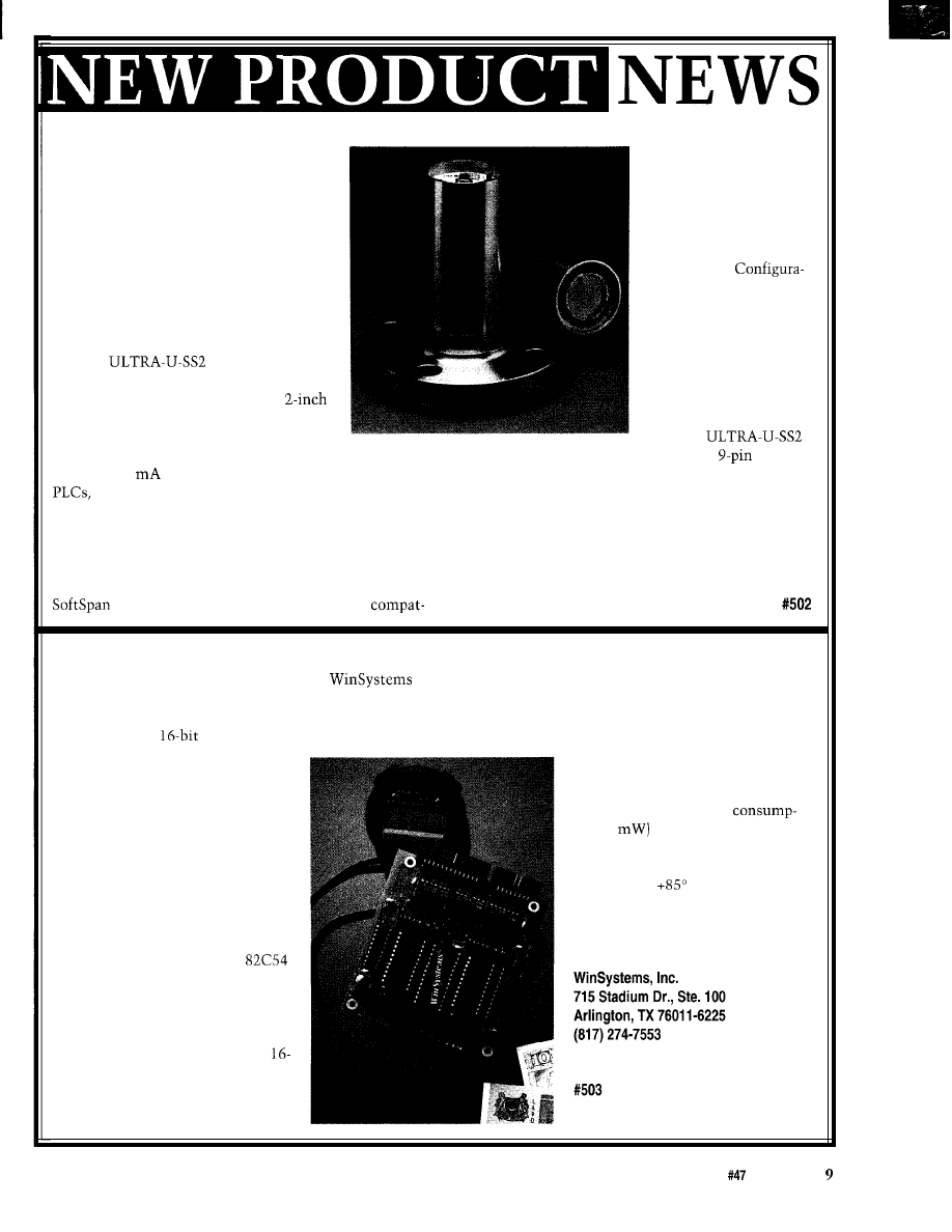
announced by Senix. The ULTRA-U-SS2
tions are permanently
can measure distances from 2 inches to 37
stored in the sensor and
feet with a repeatability of 0.1% of range
can also be stored on
and a resolution of 0.004 inches.
computer disk for future
The
is self contained
reference or duplication.
and housed in a 2.35” diameter by 5.5” long
Some adjustments are
cylindrical stainless steel case with
also provided by a rear
NPT male threads so the sensor can be
push button.
threaded directly into a 2” NPT flange. The
The
sensor communicates measured data in
includes a
female
analog (4-20
and O-10 VDC) or serial RS-232 data to
interface/power connector, alternate power jack, SET
displays, computers, and other equipment.
adjustment push button, gain adjustment, and four LED
Multisensor networks can be wired using the RS-232
indicators for Power, Target (echo], Switch 1 On, and
data communications. The sensor also includes two
Switch 2 On.
switch outputs for setpoints.
The ULTRA-U-SS2 features the ability to configure
Senix Corp.
measurement characteristics using the company’s
52 Maple St.
l
Bristol, VT 05443-1022
program, which runs on any IBM PC or
(802) 453-5522
l
Fax: (802) 453-2549
PC/l 04 COUNTER/TIMER
Output are configured by the selection of modes stored
A low-cost, 16-bit counter/timer from
in the Control Word Register. The status of the contents
has been designed to solve the common timing problems
of each counter is available to the computer for event
found in embedded system design. The PCM-CTC has
counting applications. Special logic is included so the
six independent
channels which are capable of
contents can be read “on the fly” without having to
frequency/event counting from DC
inhibit the clock input.
to 10 MHz, pulse marker or square
The PCM-CTC operates with a
wave generation, time interval
high degree of noise immunity and
measurements, and one-shot
requires very low power
simulation. All six channels are
tion (5
because it is designed
independent from each other and
using CMOS logic devices. Its
each has a buffered Clock, Gate, and
operational temperature range is
Output available to the user. The
from -40” to
Celsius, so the
individual channels can be cascaded
unit is ideal for outdoor applications
for longer count sequences, allowing
or harsh industrial environments.
maximum configuration flexibility.
The PCM-CTC sells for $125.
The PCM-CTC uses two
programmable interval timers, each
containing three independent
software programmable counter/
timers. Each counter is identical in
operation and consists of a single
Fax: (817) 548-l 358
bit, presettable down counter. The
counter can operate in either binary
or BCD and its Input, Gate, and
The Computer Applications Journal
issue
June 1994

LOW COST CAN ADAPTER
A low-cost, ISA-compatible Controller Area Net-
work (CAN) interface has been introduced by D.I.P. The
DIP051 is based on the Signetics
CAN controller
and provides a galvanically isolated interface to the CAN
through ISO/DIS
transceivers. The
adapter supports full packet management, error contain-
ment, and buffered I/O, providing both physical and data
link layer functions.
The CAN, originally introduced by Bosch for use in
automotive applications, is gaining acceptance within
the industrial control marketplace as a low-cost, me-
dium-speed interface for distributed I/O and control
solutions. A CAN operates at data rates up to Mbps and offers equal peer access between nodes. Several semicon-
ductor vendors, including Signetics, Motorola, Intel, and Siemens provide interface components and microcontrollers
which support
The DIP05 1 is supplied with sample driver software (C source code) for both interrupt and polled applications. A
low-level network monitor operating under DOS allows the user to access a CAN and to monitor bus traffic. The
DIP051 sells for $195.
D.I.P., Inc.
P.O. Box 9550
l
Valley, CA 92552-9550
l
(909) 924-1730
l
Fax: (909) 924-3359
C PROGRAMMABLE
CONTROLLER
Z-World Engineering
has introduced a low-cost
miniature controller that
features a complete
operator interface and C
programmability. The
Little Star is a simple but
powerful development
system that is well suited
for manufacturing
automation and OEM
control applications.
The Little Star
inputs and high-voltage/
high-current outputs. A
processor driven by a
system clock is
standard, with the option of
a high-speed, 1
system clock available. Two
serial ports
support asynchronous
communication at baud
rates between 300 and
57,600 (115,200
on
the
MHz version) bits per
second. Also included is
RAM and real-time clock,
EPROM, EEPROM, and an
expansion bus for additional
I/O.
The Little Star is
programmed with a power-
ful and easy-to-use Dynamic
C development system
which runs on a PC. This
interactive compiler, editor,
and debugger includes an
extensive source-code
library with many sample
programs. Dynamic C
an integrated
,
_ backed
environment consisting of a
series of windows and
menus. A separate
linker is not required since
Dynamic C links and
downloads to the target
system as it compiles.
The 4” by 5” Little
Star includes an
closure with a built-in
2x20 LCD, power supply,
and a 12-kev kevnad. The
operator interface allows the
operator to scan multiple
menus and change sys-
tem parameters using
only five keys. The op-
erator can specify only
values that are acceptable
to the control program.
The Little Star sells
for $295, including
enclosure, LCD display,
keypad, cable, manual,
schematic, and a 24-V
wall transformer. A
board-only version (no
enclosure, LCD, or
keypad) sells for $195.
The Dynamic C develop-
ment system sells for
$195. A free Dynamic C
demo disk is available.
Z-World Engineering
1724 Picasso Ave.
Davis, CA 95616
(916) 757-3737
Fax: (916) 753-5141
10
Issue
The Computer Applications Journal
NEWS
FLAT-PANEL DISPLAY
WITH TOUCHSCREEN
INTERFACE
Technolo-
gies has introduced a
system of components
that simplify flat-panel
display and touchscreen
interfacing to any
compatible computer.
The components consist
of a flat-panel controller,
flat-panel interface,
touchscreen controller
module, and touchscreen.
The
Flat-Panel Controller
supports color TFT, STN,
mono FSTN, EL, and gas
plasma panels with
resolutions up to
1280x1024. The
compatible card is
available with 256 KB of
VRAM and
VRAM
frame buffer or 5 12 KB for
higher performance. An
optional serial I/O function
can be added for touch-
screen controller communi-
cation. The card occupies
only one slot in the back-
plane and requires only one
cable for complete flat-panel
display and touchscreen
interface.
The
Interface Card simplifies the
controller to flat-panel
interconnections. It in-
cludes display cable harness,
CCFL backlight inverter,
and LCD bias supply with
brightness and contrast
controls. Power and data
sequencing are optimized
for LCD displays. A power
save mode can be activated
when the display in not in
use. The
display cable length can be
extended over 50 feet.
The
Analog Resistive
screen and Controller has a
resolution of 1024x1024
points and provides a
sample rate of 160 points
per second. This touch-
screen controller module
communicates to the PC via
a COM port in the flat-panel
display controller. The
controller sells for
$289. The
interface card sells for $79,
and the touchscreen and
controller module starts at
$249.
Inc.
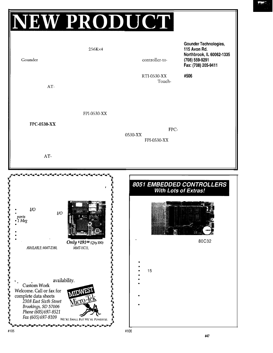
MMT-188
EB
2 serial
ports
3 programmable parallel
RAM/ROM capable
powerfail detect interrupt
and reset
We’re Small,We’re Powerful,
And We’re Cheaper.
counter- timers
watch dog timer
expansion connector
ALSO
MMT-196,
MMT-EXP
In fact, you’ll get the best product for about
half the price. If you’re interested in getting the
most out of your project, put the most into it.
For the least amount of money.
Call us today for complete data sheets, CPU
options, prices and
W e offer a full
line of low cost
e m b e d d e d
controllers and software tools which are ideal
f o r
developing products, test fixtures and prototypes.
Features Include:
Low power CMOS design
Up to 60K of code space and up to 60K of data space
5 to
volt operation
Small form factor (3.5”
l
6.5”) with prototyping area
System diskette includes application notes
Start at $100
Available Options:
Multifunction Board adds A/D, 24 I/O lines and more!
l
BASIC-52 or Monitor/Debugger in EPROM,
C Compiler $100 or BASIC Compiler for $300
Iota Systems, Inc.
POB 8987
l
Incline Village, NV 89452
PH: 702-831-6302
l
FAX: 702 831-4629
The Computer Applications Journal
Issue
June 1994
11
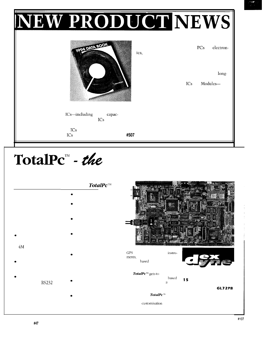
1994 DATA BOOK
The 600-page 1994
Data Book
is available
free of charge from
Benchmarq. It includes
cross-reference guides
and application notes, as
well as detailed device
specifications, quality
methodology, and
packaging and ordering
information. The new
data book describes
Benchmarq’s product focus in four categories:
users to make inexpensive SRAM nonvolatile for
EISA/MCA bus systems, portable
and
and other applications;
Nonvolatile Static and Pseudo-Static Random
Access Memory Modules-integrating, in a single
DIP package, extremely low standby power SRAM
or PSRAM, nonvolatile control circuitry, and
life lithium cells;
Nonvolatile Controller
and
providing power monitoring, write protection, and
supply switching to convert standard SRAM or
PSRAM and a backup battery into a reliable,
predictable nonvolatile memory.
Battery Management
battery
Benchmarq Microelectronics, Inc.
ity monitors and single and dual fast charge
for
2611
Westgrove Dr., Ste. 109
l
Carrollton, TX 75006
battery operated systems;
(214) 407-0011
l
Fax: (214) 407-9845
Real-Time Clock (RTC)
and Modules-including
3-V RTC for PCs and RTC
and modules that allow
embedded system
High integration compact PC controller.
STANDARD FEATURES OF
l
14 MHz PC CPU with
CGA interface for
LCD/CRT display
l
Standard PC keyboard
I/F and 12 x 8 matrix
keypad interface
Memory space for up
to 2M byte EPROM,
byte of RAM and
4MBytes of FLASH
Watchdog timer, Time
of Day clock
Floppy, IDE, Printer
and
5
serial
interfaces, two with
optional isolated
If you are making POS terminals,
systems, field portable
factory data terminals,
Ethernet
outstations or plain
process control systems for indus-
trial environments you will find
D E X D Y N E L I M I T E D
that
the heart of
your problem. Our EPROM
Version
5.0 DOS
provides
Market Place
known and proven development
Cirencester
environment for your application
Gloucestershire
software on the
England
OEM and
enquiries
Tel: 0285 658122
welcomed
Fax: 0285 655644
12
Issue
June 1994
The Computer Applications Journal

ANSI X3T9.3 specification
either
or
information like optical
for Fiber Channel and
with multiple splices or
power transmitted,
includes the open
connectors. It is supplied
optical power received,
with either duplex SC or ST
drive currents, bias
optical connectors.
voltages, and transmitter
The transceiver will
temperature. This
transmit any data stream
information allows users
from 100 Mb/s to 1.5
to diagnose network link
It can be attached to a
problems without having
receiver, and link controller
circuit board either by
FIBER OPTIC
to depend on a service
into a single 1
soldering or socketing. The
technician. The
TRANSCEIVER
package. Power
electrical pin-out is a single
85 10 sells for $660.
A fiber optic
tion is minimized because
row of 28 pins located
ceiver from Finisar drives
the transceiver uses 0.8
across the rear of the
Finisar Corp.
down the cost of gigabit
watts total operating power.
module.
3515 Edison Way
optical links by
The unit is simple to use,
A built-in link control
Menlo Park, CA 94025
ing three previously
requiring only a +5-V power
system simplifies setup and
(415) 364-2722
separate components into
supply and virtually any
maintenance of the optical
Fax: (415)
a
single, compact
differential signal input
link. It provides built-in
module. The FTR-8510
(ECL or PECL), while
optical test equipment for
Integrated Optical
operating over standard
self-test and diagnostics. In
Transceiver is fully
multimode fiber. The
addition, it can
compatible with the
optical link can operate over
report link status
EXPRESS CIRCUITS
MANUFACTURERS OF PROTOTYPE PRINTED CIRCUITS FROM YOUR CAD DESIGNS
TURN AROUND TIMES AVAILABLE FROM 24 HRS
2 WEEKS
Special Support For:
l
TANGO.PCB
l
FULL TIME MODEM
l
TANGO SERIES II
l
GERBER PHOTO PLOTTING
l
TANGO PLUS
l
PROTEL AUTOTRAX
WE CAN NOW WORK FROM
l
PROTEL EASYTRAX
YOUR EXISTING ARTWORK BY
SCANNING. CALL FOR
l
DETAILS!
l
l
II
l
EE DESIGNER I
Express
l
EE DESIGNER III
l
ALL GERBER FORMATS
0
Circuits
Quotes:
1150 Foster Street
l
Box 58
l-800-426-5396
Industrial Park Road
Phone: (910) 667-2100
Wilkesboro, NC 28697
Fax: (910) 667-0487
The Computer Applications Journal
13

FEATURES
Aero-Pix Aerial
Photography System
Programming
on a Budget
Prototyping-Beyond the
Electronics and Software
Habitech94
Ken Pergola
Aero-Pix Aerial
Photography System
I was
young, I’ve always
enjoyed flying kites
and launching model
rockets, and longed for the ability to
take pictures from the sky. When I was
in sixth grade, Estes Industries (a
model rocket company) introduced the
Astrocam 110 model rocket. This very
inexpensive rocket took a single photo
per flight from a tiny 110 film camera
embedded in the nose cone.
Launching my prized-possession
was a lot of fun, but it was always
risky and nerve racking-each launch
had the chance of being the last! It was
very easy to lose the rocket or have it
land in the most inaccessible tree
branch, only to lose all of those pic-
tures. Yes, I learned Murphy’s Law at a
very early age! My Astrocam 110’s last
flight landed in a tree; the body tube
was damaged, but luckily I was able to
retrieve the camera assembly (which I
still have today). The pictures I took
from that camera, albeit grainy, piqued
my interest in aerial photography.
Ever since, I’ve desired to take
aerial pictures with a much higher
quality camera. However, there were
always problems with that idea. For
14
Issue
June 1994
The Computer Applications Journal
R e s e r v e d
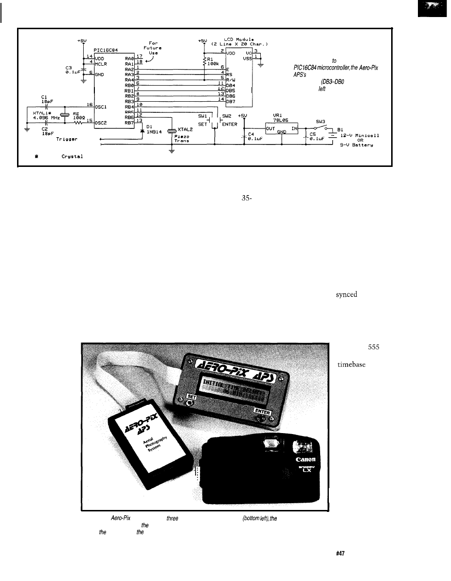
Figure l--Thanks a Microchip
circuitry requires on/y a
handful of
components
on the LCD
module are unconnected).
C a m e r a
O u t p u t
To Camera Ground4
G r o u n d
C a s e
instance, cameras in those days had
mechanically controlled shutters and a
manual film advance mechanism. The
idea of triggering the shutter remotely
became a mechanical headache. In
addition, the camera could only take
one picture at a time due to its manual
film advance. In an aerial photography
system, this would mean after each
picture was taken, the camera would
have to be reeled in, the film advanced,
and then launched back in the air. We
are talking about a lot of work here!
Therefore, the inherent lack of camera
features coupled with the engineering
problems of triggering the camera’s
shutter were the major roadblocks in
implementing a cost-effective aerial
photography
triggered shutter. The breakthrough for
me was when I stumbled across a
Canon Snappy LX camera. This
mm camera, unlike most other
inexpensive models, has its shutter
controlled by an electronic switch.
What tipped me off was the rubber
membrane switch (used as the shutter
button), much like those found in
myriad consumer electronic devices
such as infrared remote controls. This
was just what I was looking for! Best of
all, this was the least-expensive
camera in its class. I knew this was
definitely a “hackable” camera, and in
one evening I modified the camera to
be triggered externally by an electronic
signal (much like I’ve modified
stopwatches). I was quickly realizing
my dream of aerial photography!
After finding the perfect camera
solution for my project, my next step
was to design an intelligent camera
controller. I toyed with the idea of
camera triggering by an RC transmit-
ter/receiver system, but that turned
out to be too cost-prohibitive for an
entry-level aerial photography system.
The inexpensive answer was to take
pictures at a specific time interval
generated by a precise timer. A
stopwatch would be
to this
timer so the user would know when to
take pictures once the system became
airborne.
system. Thus, I
quietly aban-
doned the idea of
aerial photogra-
phy for years.
THE BIRTH OF
AERO-PIX APS
With the
advent of elec-
tronic hybrid
cameras, the
aforementioned
engineering
problems started
to quickly vanish.
Many cameras
now have auto-
matic film
advance, but most
still have a
mechanically
I quickly abandoned the thought
of using the
venerable
timer as a
for
triggering the
camera at
specific time
intervals. It was
too difficult to
generate precise
time delays;
component
tolerances of
resistors and
capacitors were
just too loose. In
addition, having
the ability to
change time
delays and the
Photo l--The
APS consists of
elements: the main controller
programming interface
number of
(fop center), and, of course, camera. The programming interface is removed from the main controller before
pictures taken
sending controller and camera a/off.
involved more
The Computer Applications Journal
Issue
June 1994
1 5
components, and system flexibility
cheapest reprogrammable chip in the
just wasn’t there. A microprocessor
Microchip PIC family.
I
don’t
was a step in the right direction, but
mend an OTP (one-time program-
would have involved support chips and
mable) PIC chip in this project because
“glue logic.” A single-chip
it would inhibit future firmware
troller was the only way to go!
updates or changes. The Aero-Pix APS
In May 1993, I saw an
is a flexible system and I want the user
ment for the PICSTART-
program-
to take advantage of this without
mer for Microchip Technology’s PIC
having to buy a new chip each time
microcontrollers. This was the second
the firmware needs to be modified.
breakthrough for this project: a perfect
one-chip solution for a camera control-
ler! I ordered the board and quickly
decided to learn about PIC microcon-
trollers and their RISC-based assembly
language. I decided that my first PIC
project would be to implement the
actual camera controller for the Canon
Snappy LX camera.
After some careful planning, I
designed the low-cost Aero-Pix Aerial
Photography System (Aero-Pix APS for
short). In this article, I’ll discuss the
simple steps necessary to build the
elegant Aero-Pix APS. This system
Tether string
enables you to take aerial pictures at a
Camera
user-programmed time delay via
(mounted in
helium balloons, large kites, or large
Styrofoam shell)
RC aircraft. The camera automatically
advances the film so multiple pictures
can be taken in one flight-just the
ticket for aerial photography!
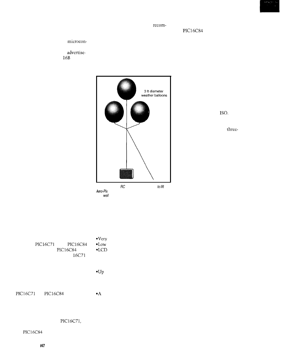
Figure
2-Kites or
airplanes may be used the
APS into the
air,
but weather balloons a/so
work
and are easy to control.
PIC AND CHOOSE
My main focus was to create an
economical and flexible camera
controller. The flexibility comes from
the use of a Microchip PIC microcon-
troller, where system upgrades and
changes can be easily implemented in
firmware. The user has the option of
using the
or the
microcontroller. The
is
more economical, but the PIC
has an on-board A/D converter for
those wanting to dabble with meteoro-
logical data acquisition in addition to
taking pictures. The Aero-Pix APS
source and executable code files are
available on the Circuit Cellar BBS in
and
formats. The
source files can be compiled with
Microchip’s MPALC or MPASM
compiler (which supercedes MPALC).
SYSTEM OVERVIEW
The Aero-Pix APS has the follow-
ing features:
l
Low-cost introduction to aerial
photography
easy to build
battery drain
user interface
*Easy programming (2 switches) with
audible feedback
*Turbo Mode for faster programming
to 36 pictures can be taken in one
flight
*Programmable delay of 1 to 99
minutes before first picture is taken
single delay of 1 to 99 minutes can
be selected between the time each
subsequent picture is taken
Even though my design contest
The Aero-Pix APS is made up of
entry was based on the
I’ve
two units: the main board and the
decided to focus this article solely on
programmer board. The programmer
the
version because it is the
board consists of the LCD module,
keypad switches, and ribbon cable and
connector. The main board consists of
the
and some auxiliary
components. The two boards are
connected via ribbon cable for pro-
gramming. After programming the
system time delays, the main board is
separated from the programmer board
so that only the main board is airlifted,
thus reducing payload weight. The
complete setup is shown in Photo 1.
The camera used in Aero-Pix APS
is the Canon Snappy LX, and can be
bought for under $60. This low-cost
camera packs many features which are
ideal for the project. The camera
automatically sets the film speed to
either 100, 200, or 400
It has a
fully automatic lens shutter and
exposure control and weighs only 7.35
ounces. The f/4.5 lens is a
element, fixed-focus, glass type. The
camera also has a lo-second self-timer.
THE CAMERA MOD
Modifying consumer electronics
can sometimes be tricky, especially
with today’s electronic hybrid cam-
eras. Fortunately the camera mod is
actually quite simple and does not
take very long to perform. Basically,
what I’m doing is bringing the various
camera switch contacts to the outside
world via a connector for external
control of certain camera functions.
Care should be taken when
working with this camera, so please
take your time and heed the upcoming
precautions. The camera mod is
actually very straightforward and does
not involve tampering with too much
inside the camera. In fact, a nice
benefit of my modification is that it
does not alter the functionality of the
camera in any way. When not taking
aerial photographs, the camera can
still be used as a regular personal
camera. The only change occurs in the
realm of ergonomics and aesthetics.
An external connector is attached to
the side of the camera. The user must
realize, however, that this modifica-
tion will void the manufacturer’s
warranty. The camera is very reliable,
though, and I’ve had it for over a year
with no problems whatsoever.
First, the camera has to be opened.
This involves removing the five small
16
Issue
June 1994
The Computer Applications Journal
screws found at various locations on
the outside of the camera, and one
screw found inside the film compart-
ment where the film is reeled in. (Do
not remove the screw that is located in
the compartment where you place the
film roll.) It is a good idea to use a good
jewelry-type screwdriver. Once the
screws are removed, it helps to keep
them together with a small magnet. It
is very easy to lose these tiny screws
and finding replacements in local
hardware stores is extremely difficult.
Next, carefully pry the two
camera halves apart. Try not to touch
the circuit board adjacent to the flash
unit. You could get a small shock from
the photoflash capacitor. If that idea
makes you nervous, you may discharge
this large electrolytic capacitor
(located at the bottom of the camera)
through a low-value resistor. Photo
shows the area of the modification.
Adjacent to the frame counter
wheel you’ll find a small board with
printed foil patterns for the carbon
membrane switches. Remove the
screw on this board and carefully lift
the board upward. Underneath you
will see the battery compartment
connectors. Solder a red wire to the
positive battery strip and a black wire
to the negative battery strip. Solder the
wires to the existing solder joints, not
to the bare metal connectors. These
connections will enable you to power
the camera externally so AAA cell
batteries can be used instead of the
heavier AA cells that the Canon
Snappy LX holds. It would be superflu-
ous to use AA cells during a flight
because the Canon Snappy LX can
shoot rolls of film on one set of AA
batteries alone, and this value is worst
case: 100% flash use. Using AAA
batteries is more than adequate. They
are lightweight and will be able to
power the camera for many rolls of
film. In addition, not using the
camera’s internal battery compartment
eliminates the chance of long-term
battery leakage, and we all know about
the perils of forgetting to remove the
batteries from consumer electronics!
As a final note, make sure you use
alkaline batteries for the camera; no
or carbon-zinc batteries please!
The switch foil pattern board is
connected to the main camera circuit
board via five right-angle pins. Some of
these pins will be tapped for external
interfacing. These pins, oriented with
the camera lens facing you, have the
following functions (from left to right):
Pin
1:
Film rewind
Photo
camera
involves simply soldering some wires onto the shutter release button contacts
and routing the wires out a small hole to an external connector. Keep in mind
such a modification voids any
manufacturer warranties, though
prevent the camera from being used to take normal snapshots.
TO
ADC-16 A/D
A/D CONVERTER” (6
Input voltage, amperage, pressure, energy
joysticks and a wide variety of other types of analog
signals.
available (lengths to 4,000’).
Call for info on other AID configurations and 12 bit
converters (terminal block and cable sold separately).
TEMPERATURE
Includes term. block temp. sensors
to 146’ F).
STA-6 DIGITAL INTERFACE’ (6
Input on/off status of relays, switches, HVAC equipment,
security devices, smoke detectors, and other devices.
STA-6D TOUCH TONE INTERFACE’................ 134.91
Allows callers to select control functions from any phone
PORT SELECTOR (4 channels
Converts an RS-232 port into 4 selectable AS-422 ports
CO-465 (RS-232 lo
l
EXPANDABLE...expand your interface to control and
monitor up to 512 relays, up to 576 digital inputs, up to
126 analog inputs or up to 126 temperature inputs using
the PS-4, EX-16, ST-32 AD-16 expansion cards.
FULL TECHNICAL
over the
telephone by our staff. Technical reference disk
including test software programming examples
C and assembly are
with each order.
HIGH
for
24
hour
applications with 10 years of proven
performance in the energy management
CONNECTS TO RS-232, RS-422 or
with
IBM and
Mac and most computers. All
standard baud rates and protocols (50 to 19.200 baud)
Use our 600 number to order FREE INFORMATION
PACKET. Technical Information (614) 464.4470
24 HOUR ORDER LINE (800) 842-7714
Express-COD
International Domestic FAX (614) 464-9656
Use for
support orders
ELECTRONIC ENERGY CONTROL, INC.
380 South
Street,
604
Columbus,
43215.5436
The Computer Applications Journal
1 7
Pin 2: Battery
reduction
lamp (when shutter button is
pressed halfway)
Pin 3: Trigger shutter (shutter button
fully depressed]
Pin 4: Common ground (for switches)
Pin 5: Self-timer
controlling the Battery Test\Red-Eye
Reduction Lamp function. These
functions are not needed for aerial
photography. It is assumed that the
user will ascertain whether the
batteries are fresh before using the
Aero-Pix APS. Nevertheless, both pins
must be asserted in order to take a
picture. Asserting the Trigger Shutter
pin alone will not take a picture. Thus,
shown as a composite, but remember
that the LCD and keypad switches are
separated from the rest of the circuit
via a connector and 16-conductor
ribbon cable. Two I/O pins (RAO and
on the
are reserved for
future use in order to have plug-in
compatibility with the
(which uses those pins for two analog
input channels for its on-board A/D
converter) if you
choose to use that
particular chip for
A/D operations. As
it stands now, the
RAO and
pins
are unconnected and
are defined as
M i c r o c h i p
Camera
LX
5u
camera
A
The Film Rewind contact (pin 1) is
not used in this project, so there is no
need to solder a lead
to it. Likewise, the
Common Ground for
the switches (pin 4)
is left alone because
we have already
tapped into the
camera ground via
the negative battery
connector. The
remaining pins will
be brought out to the
connector, however.
It would be wise to
color code the wires
and write down their
function before
closing the camera.
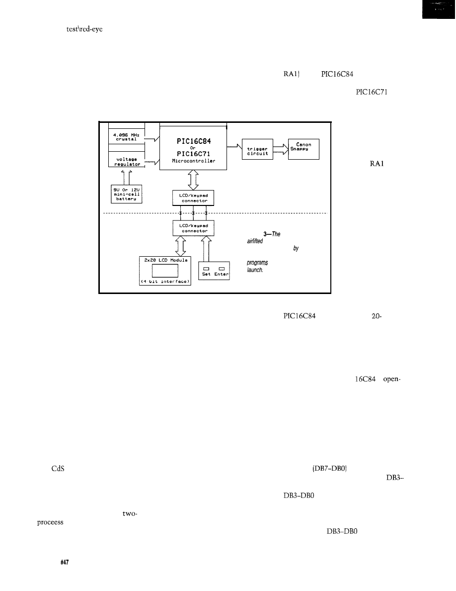
Figure
main board (top) is
and takes pictures at a time
interval programmed the user.
The programmer board (bottom)
the main board before
To reduce weight, this
board is not airlifted.
outputs for one
reason: reduced
power consumption.
If they were config-
ured as inputs,
power consumption
could be greater due
to switching
currents caused by
possible spurious
oscillation of the
floating CMOS
inputs.
A small hole
will have to be
drilled in the camera
case
to feed the wires. If you drill the
hole small enough so the five leads
just fit, there will be no need to use an
opaque epoxy to block light from
entering the camera. I strategically
drilled my hole in the battery compart-
ment in such a way that it does not
interfere with its use. Another location
for drilling a hole and routing the
wires externally is under the foil
pattern board near the external hinge.
Let me stress one important point:
as far as the shutter button is con-
cerned, taking a picture is a two-step
process. When you press the button
halfway, a green LED should light in
the viewfinder to indicate good
batteries. As a second function, if the
camera’s
cell sensor suggests flash
use, the red-eye reduction lamp will
light. Pressing the button further will
take a picture. Things change when we
automate the camera, however.
There does not have to be a
step
when the camera is
triggered by external means, mainly
because you would waste an I/O pin
in the camera interface cable that
plugs into the camera connector, the
Batery Test\Red-Eye Reduction Lamp
lead and the Trigger Shutter lead must
be connected together externally. In
this manner, you can take a picture
with just one I/O pin from the micro-
Before reassembling the camera,
make sure the lens cover latch is
controller. (Important: Do not connect
closed. Don’t forget to insert the
battery holder latch if it fell out. Now
these pins together internally in the
mate the two camera halves together.
Have patience and don’t force things
too much. If at first you don’t succeed,
camera. This will alter the functional-
you’ll get it right on the third time.
Insert all screws, but don’t overtighten
ity of the camera when not used for
them! I use Velcro to hold the camera
this project.)
connector to the camera.
CIRCUIT DESCRIPTION
Figure 1 shows the schematic of
the Aero-Pix APS. The circuit is
To conserve I/O pins, the
drives a 2-line by
character dot-matrix LCD module in
4-bit mode. The R/W line of the LCD
module could be tied low to conserve
an additional I/O pin, but I decided the
For the sake of economics, I did
benefits of reading from the LCD was
not include a potentiometer-driven
LCD contrast control. The contrast pin
well worth using the R/W line. Since
of the LCD (VO) is tied low, which
results in good LCD screen contrast for
the RA4 pin of the PIC
is
this application. Since the LCD’s data
bus lines
have internal
pull-up resistors, I opted to leave
collector when configured as an
DBO unconnected. You could also tie
directly to Vcc; from my
output, I’m using a weak pull-up
own experimentation, this would
resistor on it.
slightly reduce current consumption of
the LCD module. Whatever you do,
don’t connect
to ground; I’ve
found that current consumption will
18
Issue
June 1994
The Computer Applications Journal
significantly increase-which is
exactly what we don’t want in a
power system.
For audible user feedback of
keypresses and system operation, the
Aero-Pix APS uses a piezoelectric disc
connected to RB6 of the
Cementing the piezo disc to the inside
of the case creates a soundboard that
will amplify the sound somewhat.
The PIC
uses a crystal for a
which affords the system
precise timing control. The compo-
nents centered around the
crystal were based upon the
manufacturer’s specifications. Since it
is always a good idea to heed the
crystal manufacturer’s design guide-
lines, the values of the series resistor
and the loading capacitors will vary
depending on the brand of crystal you
choose. Otherwise, you can run the
risk of overdriving the crystal and/or
sacrificing frequency stability. Also,
make sure you ground the metal case
of the crystal. The 4.096 MHz crystal
is a pretty common part and I chose it
to simplify the
RTCC
interrupt operation.
My initial prototype uses an
inexpensive TO-92 case
voltage
regulator; its quiescent current is
significant compared to that of the
entire system. However, if lowest
possible battery drain is paramount, a
low drop-out, low-quiescent-current
V regulator can be used.
I’ve chosen to use 0.1
capaci-
tors on the input and output of the
voltage regulator to improve stability,
transient response, and to avoid the
chance of oscillation. You can never be
too careful when designing with
microcontrollers, so I firmly believe
that preventative maintenance is good
design practice. Moreover, the
power pins are bypassed
with a
capacitor.
The keypad switches are con-
nected to the PIC
without
external pull-up resistors since I
enabled weak pull-ups on port B via
firmware. Having user-configured
internal pull-ups is a very nice feature
to have on a microcontroller.
The camera trigger component is
simply a standard silicon diode
or equivalent), which also provides
isolation between the camera and the
PIC
The cathode connects to
port B pin RB7, and the anode is
connected to the Trigger Shutter pin
and the Battery
Reduc-
tion Lamp pin from the modified
camera. Normally, RB7 is at 5 volts,
but when a picture is taken,
goes
low for one second, which grounds the
cathode of the diode, allowing the
current path necessary to trigger the
camera’s shutter.
The Aero-Pix APS has two
separate supplies: 3V for the camera
and for the
and the LCD
module. For proper operation, make
sure the camera ground is connected to
the PIC
system ground. This is
sometimes overlooked when intercon-
necting various
got to have a ground to stand on! The
main board is powered by a 9-V
battery, before voltage regulation,
through a 9-V battery connector. To
accommodate a 12-V mini-cell (MN21)
battery, simply connect another 9-V
battery connector to a mini-cell
battery holder. In this way, the
battery will be retrofitted with 9-V
battery type connectors. I found that a
Radio Shack N-cell holder works fine.
Just remember to watch polarity; the
red lead of the 9-V connector will
connect to the negative terminal of the
N-cell holder, and the black lead of the
9-V connector will connect to the
positive terminal of the N-cell holder.
This seemingly reverse polarity
strategy will correct itself when you
snap the two 9-V connectors together.
The 12-V mini-cell won’t last as long
as a 9-V battery, but it sure is a heck of
a lot lighter!
THE FIRMWARE
The Aero-Pix APS firmware is my
first major programming experience
with the PIC family of microcontrol-
lers. However, I’ve tried to make the
code fairly modular so certain routines
can be ported to other PIC projects I’m
planning. I’m not an expert program-
mer, but I like to write code that uses
a lot of subroutines. This enables you
to create a “toolbox“ for future
programming endeavors. As a result,
for
C, Borland C, Borland/Turbo Pascal
Develop Real-Time Multitasking Applications under MS-DOS with
is a professional, high-performance real-time
runs under MS-DOS or in ROM
and supports
C,
Borland
Pascal,
Brook Pascal+.
is a
library you can link to your
lets you run several C
Pascal procedures as parallel
tasks.
offers the following advanced features:
preemptive,
of
only
by
RAM
up
time of appmx. 6 s
486)
.
is
of
of
full
chip
up to 64
to control your tasks
emulator
using Novell’s IPX
at run-lime
3.0 6.x,
or
system
DR-DOS,
can
interrupt rata
ms)
from
tasks
or
tasks
interrupt
and Turbo
ham disk, and
by
tasks
interrupt handlers for
available
network interrupts
with
International
add $30 shipping and handling.
Pascal
$375
Vi,
bank transfer accepted.
Programming
On Time
88
Avenue
l
NY 11733. USA
on lime
73313.3177
The
Applications Journal
Issue
1994
19
the main program portion of code is
much shorter and easier to follow.
In a nutshell, the Aero-Pix APS
firmware is based upon an
driven routine that keeps track of real
time. The main program drives the
user interface, and collects the user
programmed variables: the number of
pictures to be taken and the various
system time delays. The main program
also polls the current time and deter-
mines when a picture should be taken.
SYSTEM OPERATION
The Aero-Pix APS incorporates an
LCD module for a user interface,
which makes programming the unit
very easy. Programming involves two
switches: a SET key and an ENTER
key. Fast incrementing of parameters
is obtained by holding down the SET
key; this is what I call Turbo Mode.
The user selects the number of
pictures to take
the initial time
delay before the first picture is taken
(l-99 minutes), and a constant time
delay between each subsequent picture
(l-99 minutes). Since the Aero-Pix
APS uses a crystal-controlled
timebase, very accurate time delays
are realized. Operating the Aero-Pix
APS is very simple:
1) Make sure power is turned off and
the camera’s lens cover is closed.
2) Plug the camera trigger connector
into the Aero-Pix APS main board.
Plug the programmer board into the
main board via the ribbon cable
connector.
Switch on the power. If everything
is working properly, a series of three
short beeps should be heard. A title
screen should appear on the display
and disappear after three seconds.
5) Set the desired number of pictures
to be taken using the SET key.
(Hold down the SET key for fast
selection.)
6) When the desired value is reached,
press the ENTER key.
7) Set the desired initial time delay (in
minutes) using the SET key. (Hold
down the SET key for fast selec-
tion.) The initial time delay is the
time interval between when the
Aero-Pix APS is activated and the
first picture is taken. This delay
allows you as much time as you
need to get the system in the air
without having to worry about
wasting film on the ground.
8) When the desired value is reached,
press the ENTER key.
9) Set the desired interpicture delay (in
minutes) using the SET key. (Hold
down the SET key for fast selec-
tion.) The interpicture delay is the
time interval between when each
subsequent picture is taken. (Note:
There is no interpicture delay if
only one picture is programmed to
be taken.)
10) When the desired value is reached,
press the ENTER key. The system
is now activated. It helps to sync a
stopwatch with this last keypress.
Thus, you will know when the
pictures will be taken.
11) Disconnect the ribbon cable
connector from the Aero-Pix APS
main board, open the camera lens
cover, and launch the helium
balloons, kite, or model aircraft.
The BCC52 controller continues to be
Micromint’s best selling single-board com-
puter. Its cost-effective architecture needs
only a power supply and terminal to become
a complete development system or single
board solution in an end-use system. The
BCC52 is programmable in BASIC-52, (a
fast, full floating point interpreted BASIC), or
assembly language.
The BCC52 contains five RAM/ROM
sockets, an “intelligent”
EPROM
programmer, three
parallel ports, an
auto-baud rate detect serial console port, a serial printer port, and much more.
abii CMOS
.
Line
.
EXPANDABLE!
12
B C C 5 2
board
BASIC-52 and
$189.88
CMOS
of me
$199.88
temperature
$ 2 9 4 . 8 8
C
M
OS. expanded
$ 2 5 9 . 8 8
CALL
FOR OEM PRICING
INC.
I”
Australia:
20
June
The Computer Applications Journal

After the initial time delay has
expired, the first picture will be taken.
Subsequent pictures will be taken at
the interpicture delay interval pro-
grammed by the user.
UP, UP, AND AWAY
The medium I use to airlift the
Aero-Pix APS is three helium weather
balloons. The balloons are 3 feet in
diameter if fully inflated. On the
maiden voyage, I used a 600-foot tether
string to take pictures of the houses on
our street. I had my camera encased in
a Styrofoam shell to protect it just in
case good old Mr. Murphy and his law
were around.
The camera was set up for vertical
shots, but it can be adjusted for
oblique shots as well. Just be sure you
pick a nice still day. It’s really awe
inspiring to see the camera and
balloons float upward! If you decide to
take very high altitude shots, it might
not be a bad idea to contact your local
airport or FAA office.
I’m still in the experimental stage,
but I’m very pleased with the pictures
I’ve taken so far. The maiden voyage
occurred on an overcast day, but the
pictures were excellent. Interestingly,
the day was dark enough to trigger the
flash, which proved my stopwatch was
in sync with the Aero-Pix APS. (For
the curious, some of my aerial photos
will be available in scanned GIF
format on the Circuit Cellar BBS.) I
recently dug out those nostalgic old
pictures that my Astrocam 110 rocket
took. Hmm, maybe in 15 years I’ll be
designing a rocket for Estes that uses a
tiny CCD camera!
THE SKY IS NOT THE LIMIT!
The Aero-Pix APS is highly
flexible and can also be used for
applications other than aerial photog-
raphy. Let your imagination run wild!
The Aero-Pix APS can be used in any
application (except stop-action
photography) that requires an elec-
tronically triggered camera.
such application could be home
security in which a motion detector
could theoretically capture an intruder
on film. Another application could
be for wild animal tracking and
research.
The Aero-Pix APS is a
effective way to enter the realm of
aerial photography. And best of all, it
is simply a fun project! After spending
many hours inside designing this
project, it is great to enjoy the fruits of
my labor outdoors.
Ken Pergola holds a B.S. in Electrical
Engineering Technology from S. N. Y
Institute of Technology, and dedicates
this project to his beloved brother
Steven.
For further information, please
contact Ken Pergola on the
Circuit Cellar BBS or at 2088
Swamp Rd., Richmond, MA
(413) 698-3167.
A preprogrammed PIC
microcontroller may be ordered
from the above address for $25
(shipping included in price).
Canon Snappy/LX camera:
Service Merchandise, Wal-Mart,
Ritz Camera
crystal, LCD module,
voltage regulator: B.G.
Micro
or
Project cases: Radio Shack.
Meteorological weather balloons:
Edmund Scientific
8880), part
they also
sell cheaper, nonweather
balloons, part
Safesport
Mfg. Co.
part
3 ft. diameter (Safesport
will not sell directly, but you can
call to obtain local distributor)
Software for this article is avail-
able from the Circuit Cellar BBS
and on Software On Disk for this
issue. Please see the end of
in this issue for
downloading and ordering
information.
401
Very Useful
402 Moderately Useful
403 Not Useful
it’s a high integration, 9951 with:
8
10 bit A/D
2 PWM outputs
registers 16
lines
RS-232 port
Watchdog
made the
adding:
multi-drop ports
24 more
Real-time Clock
EEPROM
l-ROM
Battery Backup Power Regulation
Power Fail
Expansion Bus
Start
the
all the
peripherals, power
manual and a
debug monitor for
$949. Download
Your code and debug it right on this
Then use the $149 and up OEM boards
for production. or have us make a custom
board for
Call now for a brochure!
Intel
Two 1 meg Flash/ ROM sockets
Four battery backed, 1 meg RAM
16 channel, 12 or 16 bit A/D
channel, 12 bit D/A
2
serial, 1
24 bits of opto rack compatible
20 bits of digital
Real-time clock
Interrupt and DMA controller
8 bit,
expansion ISA
on the quiet, 4 layer board is
a switcher with watchdog and
fail interrupt circuitry
is also available with
Extended interface Emulation of I/O a
and a breadboard area. You can now
define and design nearly any extra interface
you need.
prices start at $299.
for a brochure!
$ 1 4 9 8 0 3 2 I C E
Still A vailable!
8031 SBC
as
as
S i n c e 1 9 8 3
(619) 566-l 892
70662.1241
The Computer Applications Journal
Issue
June
21

Russ
Reiss
Programming
on a Budget
to start using PIC
your applications, but
were put off by the cost of the pro-
gramming tools? Or have you wanted
the ability to program a microcontrol-
ler without having to first remove it
from the circuit and erase it? If you
answered “yes” to either of these
questions, then consider using the new
Microchip PIC
This EEPROM-
based microcontroller offers many
benefits to the embedded system
designer. As with previous PIC
devices, one tiny package contains the
CPU, program memory, working
RAM, a real-time clock/counter
(RTCC), and I/O bits.
The use of EEPROM makes the
powerful, flexible, and
simple to use. One device may be used
both for development and production.
Since no UV light source is required
for erasure, it has a lower cost than its
quartz-windowed
package)
cousins. The user-data EEPROM space
eliminates the need for a separate
EEPROM package in the design. But
more importantly, the device may be
programmed on board without
removal. This allows newly manufac-
tured boards to be programmed after
assembly. It also permits systems to be
field upgraded and eliminates potential
problems from static discharge and
bent pins. The only catch here is that
the system must be designed to permit
access to the programming pins. But,
as you shall see, this is a relatively
simple matter.
Now that you are sold on the
merits of the EEPROM-based
PIC
how do you go about
accessing its programming pins and
actually getting one programmed?
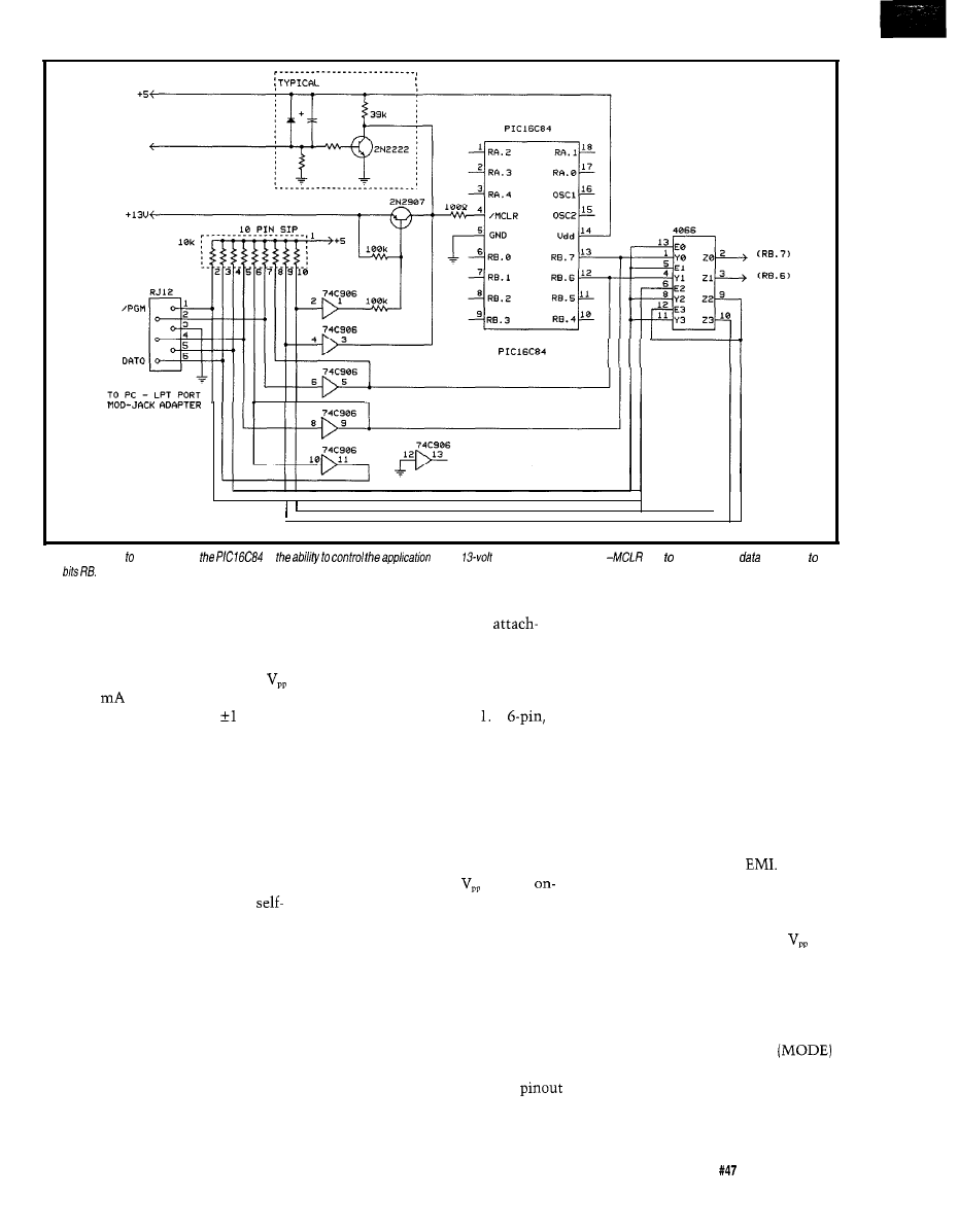
SERIAL PROGRAMMING THE PIC
After becoming intrigued by the
The
is very similar to
the
but without an A/D
converter. It is housed in an 18-pin
package and contains
words of
program space, 36 bytes of RAM, plus
13 (RA and RB) bidirectional I/O bits.
It also supports various interrupt
sources and has an
stack.
many possibilities the PIC
had
to offer, I soon realized that it also
offers one other benefit: truly low-cost
programming. So, I set out to develop
means by which a conventional
compatible PC could be used as a
development programmer. The result
is a PIC programmer which costs less
than a cheap
erasing light-which,
of course, is no longer even required.
The
program
The PIC
may be pro-
memory is in the form of EEPROM
grammed in two ways: serial or
rather than EPROM. In addition to the
parallel. For simplicity, on-board
normal working RAM, there are 64
programming using the serial method
bytes of nonvolatile EEPROM space
is the way to go. Only three pins (RB.7,
for storing setup information, system
RB.6, and
need to be
configuration options, user data, or
accessed. Program/test mode is entered
real-time data. The device configura-
by raising
to a
tion bits that set protection mode,
voltage programming level
of 13
power-on timer enables, watchdog
timer, RTCC modes, and oscillator
type are also implemented in
EEPROM, although they are only
accessible in program/test mode.
Nevertheless, it is no longer necessary
to stock different devices when both
RC and crystal oscillators are required
in different applications.
22
Issue
1994
The Computer Applications Journal
USER CIRCUITRY
RESET
CLK
GND
DATI
MODE
NOTE:
ALL UNCONNECTED PINS
OF
GO TO
USER CIRCUITRY
TO USER
CIRCUITRY
Figure l--The key
programming
is
of the
programming voltage fo
and provide serial
and clock
porf
7 and RB.6.
volts while holding RB.7 and RB.6 low.
In this mode, RB.7 serves as a bidirec-
tional data line while RB.6 accepts a
user-generated clock.
While the current drawn from
is only 1
worst case, this voltage
must be accurate to within volt,
and it must have a rise time of less
than 1 us. The clock rate, which
determines how fast programming
commands are sent to the PIC, may be
anything from DC to 5 MHz. How-
ever, since the EEPROM requires 10
ms per byte for its internal program
cycle, there is little to be gained by
pushing the clock rate to extremes. As
you will see later, this internally
paced timing reduces the requirements
on the PC programming software.
All we need to do is to supply
these signals in the proper format in
order to send programming commands
and data to the device. However, first
we must isolate the three pins from
other on-board circuitry.
DIVIDE AND CONQUER
In new designs, it is possible to
incorporate all the circuitry necessary
for programming right on the target PC
ment of the “programmer,” which is
simply a few bits from the parallel port
board. A connector permits
of a conventional PC. A schematic of
typical on-board programming cir-
cuitry is shown in Figure A
modular RJ-12 “telephone” connector
is used for interconnection. A standard
6-conductor, telephone-type, modular
cable connects to the PC’s parallel port
via a modular-jack adapter. The rest of
the programmer is composed simply of
software running on the PC. Note,
however, that this design assumes you
either have a source of
already
board or can supply it externally
through a connector.
adapter. The color code for wires is the
for the RJ-12 on the target board.
typical standard for the telephone
market. Be certain, though, that you
use the convention of pin 1 being the
Figure 2 shows the wiring of the
first one on the left when the “contact
fingers” are at the top of the jack.
Signals are arranged on the cable in
such a manner that dynamic signals
are interspersed with static (or
pseudostatic) signals. This improves
the high-frequency transmission-line
properties of the cable and also
minimizes any potential
Returning to the circuitry of
Figure 1, its purpose is to isolate the
programming pins, to interface with
the PC, and to drive -MCLR to
level during programming. The
switchover from normal operation to
programming mode is achieved
automatically (once the programming
cable is attached) by the PC placing a
low level (zero volts] on pin 5
of the interface connector. Operating
power is supplied as it normally would
be to the target system. Ensure that
the PC is powered up whenever the
A few words about RJ-12 connec-
tors and “telephone-style” modular
cables are in order. When a modular
plug is crimped onto a flat cable with
the same orientation at each end, a
reversal in pin assignments occurs.
This is typical of stock modular cable
assemblies you might purchase for use
with telephones. Therefore, the
of the RJ-12 on the adapter will appear
to be (and is) reversed from that shown
The Computer Applications Journal
Issue
June 1994
2 3
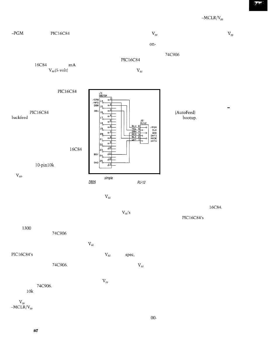
programming cable is attached and the
target board is running. Otherwise, the
PC could present a low on MODE and
and
cause
the
to
enter programming mode. However,
when the PC is powered up or when
the cable is removed, you can operate
the target board normally (whenever
MODE is high).
The PIC
requires 20
maximum from the
source
in program/test mode. If desired, the
rest of the on-board circuitry can be
left unpowered during programming by
segmenting power to the
and incorporating a removable jumper.
This is not mandatory since the
peripheral circuitry is only powered
when the
is too, and cannot
power through the I/O lines
as often occurs with CMOS devices.
In the design in Figure 1, a CMOS
4066 analog switch is used to isolate
RB.7 and RB.6 from internal circuitry
during programming. Since internal
“weak pull-ups” within the PIC
on the RB.7 and RB.6 pins are not
activated in program/test mode, two
sections of a
SIP resistor
network are used to pull up these pins
to
The extra sink current required
by these resistors usually has no effect
on the on-board circuitry driving these
pins, but should be taken into account
in the design. When not in program/
test mode, these analog switches
establish connection to the on-board
circuitry. Keep in mind when design-
ing on-board circuitry, however, that
maximum on resistance of these can
reach
ohms worst case.
Two sections of a
hex
open-drain level translator chip are
employed to drive these pins from the
PC’s TTL signals. Data from the
bidirectional RB.7 data pin
is buffered and fed back to the PC by
another section of the
Its
output is also pulled up since this is an
open-drain device. The CLK signal is
buffered and fed to RB.6 by another
section of the
The pull-up
value of
is needed to establish
reasonable rise time of these signals.
must be switched onto the
pin during programming.
Since the 4066 cannot withstand this
high potential, it cannot be used for
isolation as was done above. Also,
special consideration must be given to
the on-board circuitry attached to this
pin. We must ensure that the high
level does not feed back and have
undesirable consequences for the
board -MCLR circuitry.
Luckily, -MCLR circuitry is often
quite simple. The
generates
its own power-on-reset (POR) signal as
long as the supply voltage
rises
rapidly enough (faster than 50 volts/
second). When this is the case, -MCLR
Figure
2-A
adapter is used to go between the
connector on most PCs and the
jack used
on fhe programmer board.
is tied to
through a resistor of less
than 40k (to meet the leakage specs for
this pin). External circuitry is required
on -MCLR only if
rise time is
slower than that required for auto-
matic POR or if the microcontroller
needs external reset capability.
In these cases, a transistor is often
used to hold -MCLR active low until
is fully on (or to generate a reset],
as is shown in the dotted area of Figure
1. When
is up to
this transis-
tor turns off, which allows the pull-up
resistor to bring -MCLR to
level,
releasing the reset to the chip. Using
the circuitry shown, presence of the
13-volt
level at -MCLR has no
deleterious effects. Should more
complex on-board -MCLR circuitry be
required in some application, the
simplest approach is to incorporate a
jumper that can be removed to isolate
this circuitry while programming. As
is recommended by Microchip, a 1
ohm resistor on the
input
should be included to protect this pin
against ESD transients.
As you can see from Figure 1,
is switched onto the -MCLR pin
during programming by a conventional
PNP pass transistor. A section of the
holds -MCLR active low when
the program voltage is removed. The
extra circuitry involving the bottom
two sections of the 4066 is some logic
which guarantees that the program-
ming circuitry stays “out of the way”
when no programming cable is
attached. When the cable is attached,
however, the MODE pin should be at
a high level initially. Since this signal
is driven by the PC parallel port’s
AFD
signal, that is the case
just after
It is also initialized
(and returned) to a high level by the
programming software. It is brought
low (MODE=O) only during program-
ming. If the programming cable is left
attached when the PC is powered
down, however, this signal can pull
low and interfere with normal opera-
tion of the target board.
When the circuitry shown here is
incorporated in a microcontroller
design, programming is a very simple
matter. Simply attach the cable
between the target board and the PC
(via the modular jack adapter) and
apply power. Then run the program-
ming software (discussed below) to
read or program the PIC
Since
this interface permits the PC to read or
write the
user data
EEPROM area, a laptop computer
could be used to access real-time data
from units in the field.
THE “KISS” APPROACH!
Often it is not possible or desir-
able to incorporate the programming
circuitry on-board. This might be the
case when size is of great importance
or when the board is already laid out.
It is also costly in some cases to
incorporate programming circuitry on
every board when it will be used only
occasionally. In these cases, a simpler
approach is desirable. It is possible to
move the programming circuitry to an
external adapter board, leaving just a
simple programming header on the
target board. Often such a simple
24
Issue
June 1994
The Computer Applications Journal
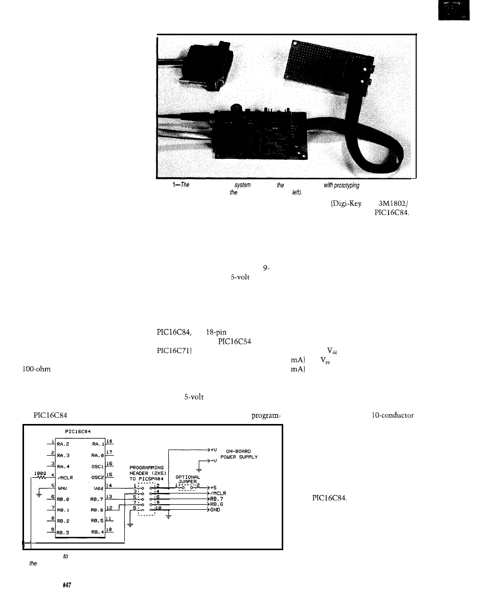
addition can be retrofitted even on
existing boards.
The organization of the program-
ming header is important if simple and
convenient use is desired. The layout
shown in Figure 3 has proven to be
very appropriate. A small 2x5 header is
used. Signals are arranged so that a
multiposition “shunt” (or individual
jumpers) can be placed over the header
pins during normal operation. This
arrangement passes the signals on one
side of the header to the other side. In
this mode, the circuit behaves nor-
mally. When you want to program the
microcontroller, the shunt is removed
and a plug with ribbon cable is
attached in its place. Removing the
shunt isolates the programming pins
from on-board circuitry.
This cable connects to a Serial
Programming Adapter (SPA) which
also connects to the PC’s parallel port
via the modular jack adapter. The use
of ribbon cable also permits in-line
DE9 IDC connectors to be inserted in
the run if panel mounting is required.
In that case, the extra ground on pin 10
would be omitted from the DE9
connector. It is obvious from Figure 3
that this represents the simplest
possible approach. No changes to the
existing circuit design are required
since the programming pins are
completely isolated from on-board
circuitry in programming mode. The
ESD protection resistor
recommended by Microchip should be
located where shown so it is in the
circuit at all times.
If you wish to experiment with
the
and serial programming,
Photo
basic
development
consists of application board
area (upper right), the
programmer board (center), and modular adapter (upper
you need a board with a serial pro-
gramming header on it. While you can
retrofit an existing board, I designed a
prototyping board (PICPR084) which
incorporates the serial programming
header and everything else needed for
simple applications. As shown in
Figure 4, this board also includes
volt battery clips and a
regula-
tor, provision for RC or crystal
oscillator, connection points for all RA
and RB port signals, and a 1.5” square
prototyping area. Although geared
specifically toward the EEPROM
any
PIC microcon-
troller (such as the
or
may be used on the
prototyping board. If battery power is
not your thing, an external power
connector and jumpers are incorpo-
rated which permit use of either an
external
source or an unregu-
lated supply up to 25 volts. Sufficient
room is allowed so that a ZIF
TO ON-BOARD
USER CIRCUIT
Figure 3-/n
order minimize recurring expenses on production boards, a programming header may be included
on board and an external programming board plugged in only when needed.
ming socket
P/N
1805) may be used for the
This way, microcontrollers may be
programmed on the PICPR084 and
then used elsewhere.
HARDWARE FOR THE SPA
The PICSPA84 (Serial Program-
ming Adapter) design, as shown in
Figure 5, is a simplified version of the
on-board circuitry presented earlier. It
is simpler because the analog switches
are not needed for isolation. That
function is provided by the program-
ming header and removable shunt. The
SPA also includes provision for
generating
(5 volts at more than 25
and
(13 volts at more than 50
from a low-cost wall-pack
transformer. As you can see from the
schematic, a 2x5 header-identical to
the layout used on the target or
prototype board-permits interconnec-
tion via a short length of
ribbon cable. On the other side of the
SPA, connection to the PC’s parallel
port is via the standard RJ- 12 6-pin
“telephone connector.” The SPA is an
external block which inserts between
the PC and the target board and
contains everything necessary to
interface with the programming pins
of the
A word or two about the power
supply section is in order. To keep
cost low, an external wall-pack AC
transformer (or DC supply) is nor-
mally used. Any type of supply will
work so long as it produces greater
than 13 VAC or 16 VDC. The Radio
26
Issue
June 1994
The Computer Applications Journal
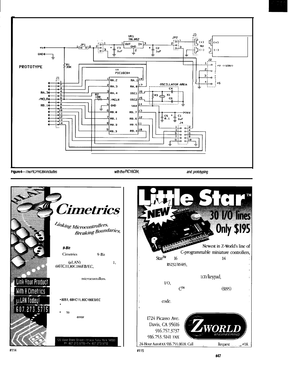
TO
AREA
JP3
NINE-UOLT
BATTERY
RF1.O
RFI.l
RC1.2
RA.4
RB.O
RB.2
RB.3
REJ.4
RB.5
RB.6
REI.7
GNC
GND
everything necessary for experimenting
including a programming header
area.
T
E
C
H
N
O
L
O
G
Y
The
Solution
The
Technology
Solution is a complete microcontroller
network
that supports the 805
and many other
popular processors. The Y-Bit Solution
takes full advantage of microprocessor
modes built in to
The Y-Bit Solution allows simple and
inexpensive development of master/slave
multidrop embedded controller networks.
compatible
A full range of other processors
supported
Up
250 nodes
. 16 Bit CRC
checking with
sequence numbers
. Complete source code included
the Little
has protected digital inputs, high-current
driver outputs,
battery-backed
RAM
and real-time
clock, programmable timers, watchdog, and more. The Little Star
is also available with enclosure and
expansion cards
for additional
and optional
18
MHZ
clock. Our easy-to-use,
yet powerful Dynamic
development system
integrates
an editor, compiler, debugger, and dozens of software libraries
all in source
The Little Star is ideal for
OEM
control appli-
cations, manufacturing automation, test and data acquisition.
from vour FAX.
catalog
The Computer Applications Journal
Issue
June 1994
2 7
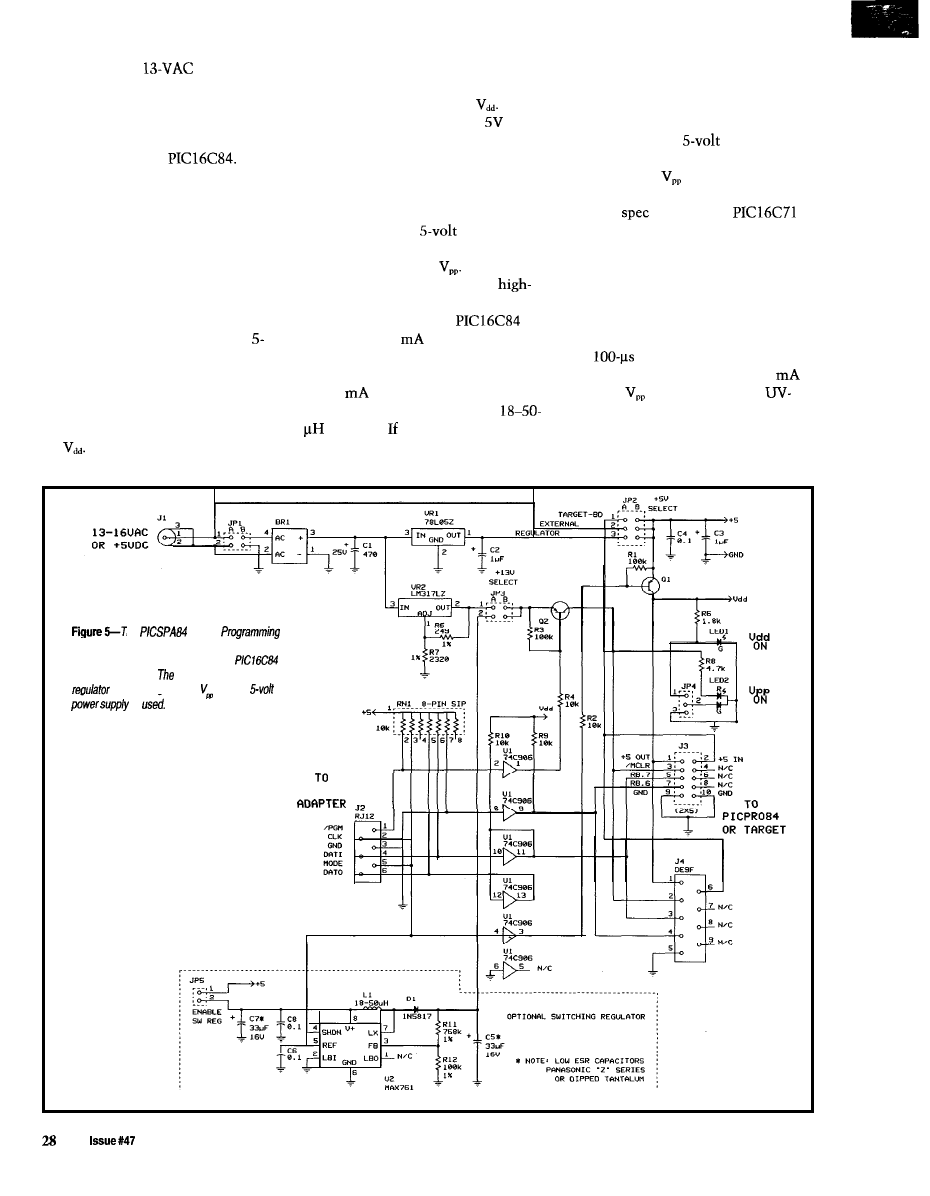
Shack 273-1610
pack is
selects the output of the 5-V regulator.
and also ensure that the target system
suitable.
The third position uses the external
(or regulated source connected to the
The supply feeds a bridge rectifier
power jack as the source of
With
power jack) can supply the extra
and low-power linear 5-V regulator for
this third option, a regulated
supply
current the switching regulator
powering both the PICSPA84 circuitry
must be connected in place of the
demands from the
supply.
as well as the target
wall-pack transformer and jumper JP 1
The desirability of using this
Programming voltage is generated by a
must be moved to its alternate
higher-current
source might not be
separate LM3 17LZ adjustable regulator
set to provide a 13-volt output. The
DC voltage at the output of the bridge
should be restricted to less than 25
volts in order not to exceed the rating
of the filter capacitor and the power
dissipation capability of the regulators.
In some cases, the user might
wish to power the setup from the
volt power source in the target system.
This voltage is fed over the program-
ming ribbon cable to the PICSPA84
and is available for use. Jumper JP2
selects one of three possible sources
for
One position picks up 5 V from
the target system. A second setting
position so it grounds one side of the
power jack and isolates the bridge.
When using a
source with
sufficient capacity, we have another
option for generating
An area of
the PICSPA84 is set aside for a
efficiency, low-power, step-up switch-
ing regulator. While the
requires only 1
from this supply
during programming, I use a “beefier”
MAX761 regulator. It is capable of up
to 120
output, yet uses only nine
components, including a small
inductor. this option is chosen,
the user must install these extra
components, reconfigure the jumpers,
immediately apparent. But should you
read the
sheet for the
device, you will see that the same
serial programming approach may be
used for it as well. Timings are
different, however. In fact, they are
much more stringent since program-
ming is not internally self-timed (as it
is with the EEPROM devices). Accu-
rate
programming pulses are
needed. Also, it requires up to 50
from the
source since it is a
erasable device. But with suitable
modification to the software, both
devices can be handled with the same
SPA design. Besides, there are few
he
(Serial
Adapter) plugs into the programming header of
the board in Figure 4 to program the
while on the board.
optional switching
is used to generate when a
is
PC LPT
June 1994
The Computer Applications Journal
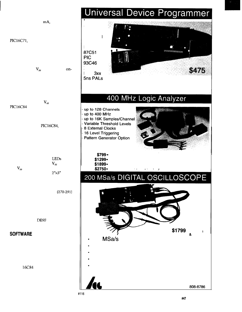
single-chip switching regulators that
put out less than 50
and they are
neither smaller, simpler, nor signifi-
cantly less expensive than the
MAX761 used here. When using a
however, don’t forget that
while a blank chip can be programmed
in the target system, you may need to
remove it for erasure. Also, of course,
the user data EEPROM doesn’t exist.
On the PICSPA84, the -PGM
signal switches
as it did in the
board design. An active pull-down is
not needed, however, since we have
isolated all user circuitry, including
the -MCLR pull-up, by removing the
shunt. The MODE signal serves a
slightly different, but compatible,
purpose. It switches
to the
since on-board power is
isolated by the shunt. To eliminate
any possibility of “backfeed” of power
from the target board circuitry through
the I/O pins of the
power to
the target board should be left off (or
disconnected by the optional jumper
shown in Figure 3) whenever the SPA
cable is attached. MODE is also used
to activate the switching regulator (if
used] whenever the PICSPA84 is put in
programming mode. Two
indicate to the user when
(Green)
and
(Red) are applied to the PIC.
I’ve designed a small
PC
board for building the adapter and am
making a kit available (see the sources
section). The board is designed to fit
into a modified Radio Shack
small plastic box. Since this box has
one predrilled hole located close to the
position of LED2, I made provision on
the PCB to use a single bicolor LED as
a dual-mode indicator. The board also
permits use of a
connector in
place of the 2x5 header.
IS THE KEY
As is so often the case, simplifica-
tion of the hardware often results in
the need for specialized software to
drive it. This is true here, too. The
parallel port is not used in its normal
manner, but to “bit bang” signals to
the PIC
via the SPA. However,
the effort that went into developing
the programming software involved
much more than just generating the
parallel-port signals with proper
PAL
GAL
EPROM
EEPROM
FLASH
MICRO
XC1 736
PSD
Free
software updates on BBS
Powerful menu driven software
LA12100
(100
MHz, 24
Ch)
LA32200 (200 MHz, 32
Ch)
LA32400 (400 MHz, 32
Ch)
LA64400 (400 MHz, 64
Ch)
Price is Complete
Pods and Software
included
- S t a r t i n g a t
With Pods
Software
200
sampling Rate
2 Analog Channels (2 ch. Digital Oscilloscope)
8 Digital Channels (8 ch. Logic Analyzer)
125 MHz Single Shot Bandwidth
up to 128K Samples/Channel
Call (201) 808-8990
Link Instruments
369 Passaic Ave, Suite 100, Fairfield, NJ 07004 fax:
The Computer Applications Journal
Issue
June 1994
29

format and timing. Most of the effort
went into reading and writing object
files produced by assemblers/compilers
in various formats, providing capabil-
ity for editing data, and creating a
convenient user interface. The result-
ing program,
P I C P GM84 E X E,
achieves
these results. A basic version of this
program is available for downloading
from the Circuit Cellar BBS. A regis-
tered version with more features,
including support for the
is
available on disk.
The “simple” part of the software
is talking to the SPA (or, equivalently,
to the on-board programming circuitry,
since they look identical to the
software). Since the rate of the
PIC
programming clock
permits operation at DC to 5 MHz,
there is nothing critical about the
banging” used to generate the data and
clock signals fed to RB.7 and RB.6.
Required setup and hold times of 100
ns are easily achieved through normal
program delays, even on the fastest of
PCs. The required intercommand gap
of 1 minimum is also achieved
through program delays.
As I mentioned previously, there
is no need for special efforts to push
the clock rate. As implemented, the
time needed to send a typical com-
mand and its data is around 1 ms. This
is small compared to the 10 ms per
byte required by the
internal timer. Be sure to note that the
programming period is a target
value, but early chips did not meet this
To allow for slower (and future,
faster) devices, the software permits
the user to specify any duration in
increments of 1 ms. A side benefit of
slower clock rates is that cable length
becomes much less critical, permitting
more convenient location of the
adapter. Use of Schmitt-trigger inputs
by the
on RB.7 and RB.6 in
programming mode ensures clean
operation.
Since the
in serial
program mode does not possess a
“bulk erase” capability (although it is
available in parallel mode), we nor-
mally program the full 1 K program
memory to ensure that any old data is
completely overwritten. This opera-
tion takes typically less than 15
The Data Format Quandary
Intel hex formats have been used for years as the standard for object
files sent to device programmers. Probably the most popular one is
Merged). This is a byte-oriented protocol and
requires special definition to support the
PIC program data. All
characters in the file are ASCII characters, which makes it simple to
inspect and process the data. The format is:
Here,
is a lead-in character which says that a block of data follows.
is a byte count,
is a starting address for the data in the block,
is a two hex-digit (ASCII) field which specifies the type of data. It is
always 00 except for the end-of-file terminator where it is 01. Each pair of
ASCII characters XX specifies one data byte, and CC is a one-byte
checksum. A typical block might look like:
This line specifies that 16 (decimal) bytes are contained in the block.
The starting address for data is
The next 00 is the flag that says this
is normal data. The following 32 ASCII characters specify 16 bytes of data
to
The last pair of characters is a checksum.
Even though the characters in the file are ASCII, the checksum is
performed on the hex digits they represent. The sum of all bytes (including
the checksum, but not including the
must add up to zero. The
checksum is chosen to make this happen. the above example, the sum of
all the bytes preceding the checksum is 84E (hex). We drop all but the two
least-significant digits, which gives 4E. The checksum must then be B2,
since when we add this to 4E we get 00 (ignoring the carry).
A typical terminator line looks like:
This signifies that we have no data bytes, a dummy address of 0000,
the terminator flag 01, and the checksum FF. The special block produced
by the Parallax PASM71 assembler for ID and configuration information
might look like:
This indicates five bytes of data at a starting location of OFFB. The data
bytes 41-44 represent ASCII characters “A” through “D” for the ID code.
The fifth byte, 13, is configuration bit data. The checksum is D4. Only a
program which recognizes that address OFFB represents configuration
information (and that
I
D bytes occupy only the low seven bits with the
high seven filled with ones) would be able to make proper use of this block.
Certainly not a very universal approach to life.
Note that
is a byte-oriented format. Addresses are byte
addresses and data are individual bytes. How do these data relate to the
bit word of the
(and others)? The
word is assumed to be
right-justified in a 16-bit word. This word is split into two bytes with the
low-order byte coming first in the line of data followed by the high-order
byte. They thus appear swapped. The four-digit addresses, however, do not
have their bytes swapped. Note that these are byte addresses and, hence,
are double the word addresses of the program.
30
Issue
June 1994
The Computer Applications Journal
seconds. For special situations in
which only a portion of the EEPROM
needs to be modified, the programming
software permits the user to specify a
partial region. Additionally, any region
of the user EEPROM area as well as
the ID and configuration bits may be
read or programmed. Data read from
the
may be saved as a hex
file.
One thing I soon learned is that
there is not complete standardization
with respect to object (hex) file
structure. While Microchip often
specifies
Merged) format for data (see the
sidebar), 16-bit formats and even
binary files are sometimes employed.
This makes some sense since the
actually uses
data
words. However, rather than compli-
cate the programming software unduly
and restrict ultimate compatibility,
only the popular
format is
used by PICPGM84. Conversion
programs are available or may be
written to translate other formats into
this standard.
Another area of incompatibility
that arose during development is in
specifying user-data EEPROM, ID
codes, and configuration bit data.
Microchip encourages this information
to be included in object files, but the
actual means is not totally standard-
ized. User-data EEPROM is a
wide area, thus
is a natural
format to use for it. ID codes are
actually bits in size, although they
recommend using only the low-order 7
bits so ID information may be verified
even if the code protection bit is
programmed. The configuration bit
word is 14 bits wide, but only the
least-significant 5 bits are used. As an
example of the incompatibility that
exists, the Parallax
assem-
bler, for example, produces a special
byte block in the hex file for ID and
configuration bit data, and assigns it to
address
as shown in the
following sample block:
ID = “ABCD” FUSES = h
This approach restricts ID codes to
single bytes.
Intel
hex format
is similar, but the high and the low
data bytes are not swapped nor are the addresses doubled. This format
would seem to be more natural for the
PIC. However, recall that the
user data EEPROM area is only byte wide.
Binary format is a file (usually with a .BIN extension) which contains
pure
binary numbers with no markers, addresses, or checksums. It
represents a block of data which could reside anywhere in memory. Thus,
we need to know the starting location, which for most purposes is usually
taken to be 0000. For large amounts of data, the file is more compact, but
it lacks useful information for a programmer. It also implies that an entire
memory map is supplied, which can be wasteful if program data, user
memory, and configuration information are mapped to disjoint areas as
with the PIC. Furthermore, not being an ASCII file, it is difficult to read or
edit using simple tools.
The most straightforward ap-
to follow is the address
ping suggested by Microchip. This
places program data at
user data at
ID codes at
and configuration bit
data at
If the object file follows
these conventions, PICPGM84 will
properly read all this information
automatically. If not specified,
PICPGM84 sets all unused program
memory to
data memory to
and ID codes to
just as a
blank chip would look. It leaves all
configuration bits unprogrammed
This configures the
for no code protection, power-up and
watchdog timers enabled, and RC-type
oscillator.
mentioned earlier, this offers a lot of
flexibility for the user.
I
wrote the PICPGM84 software in
C to run on any IBM-compatible PC
regardless of its speed. It calibrates
delay loops based on the CPU’s speed.
When programming PIC
(with
their internally timed EEPROM
program cycle), operation under
Windows or OS/2 with other activities
generating interrupts should be
possible. But if used to program the
(with its tight program
pulse requirements), it should run as a
stand-alone program with
and
other devices inactive. In all cases, no
other devices should attempt to use
the
port whenever the SPA is
attached. Otherwise, inadvertent
programming could take place.
If the assembler or compiler
produces object code for these special
areas using a different convention (as
I
found with the Parallax PASM71
assembler), either the object file must
be passed through a translator to
produce a file meeting standard
convention, or the data may be
patched by hand using
editing capabilities.
The program occupies around
and requires EGA or better video
operating in
mode.
As with most software, PICPGM84 is
an evolving program, and if there is
interest, I will make more advanced
versions available in the future.
CONCLUSION
PICPGM84 also permits the
With the PIC
Serial Pro-
reading of just the user-data EEPROM
gramming Adapter
and configuration bit data from a file.
Prototyping Board
and
This capability is useful in at least two
PICPGM84 software, getting started in
situations. At times, the user data and
the fun of applying
to embedded
bit data may be fine and only the
applications just got a whole lot
program needs changing. Other times,
simpler and less expensive. No more
the program is cast in concrete and
expensive windowed/erasable chips,
only the user data needs reprogram-
no more UV erasers, no more program-
ming, for example to load calibration
mers costing over $100, and no more
data or serial numbers. Combined with
removing chips from the board for
the partial programming capability
reprogramming.
q
32
The Computer Applications Journal
Russ Reiss holds a Ph.D. in
and
has been active in electronics for over
years
as
industry consultant,
designer, college professor,
neur, and company president. He may
be reached at
or
All components needed to build the
circuits presented here
(except
are available from standard suppliers
such as
and Mouser.
The following are available from
HOPCO, P.O. Box 2425, Vernon, CT
06066:
1. Complete parts kit for the
PICSPA84 including PC board, all
components, and three-foot pro-
gramming ribbon-cable assembly
(switching regulator components
not included] . . . . .
$35.00
2. Above unit assembled and tested
. . . . . . . . . . . . . . . . . . . . . . . . . . . . . . . . . . . . . . . . . . . . .$65.00
3.
PC parallel port
adapter, modular telephone cable
assembly, and wall-pack
former (PICACC84)
$15.00
4. Parts kit for PICPR084, including
PC board, serial programming
header, 9-V battery clips, 5-V regu-
lator,
RC oscillator, and
position shunt . . . . .
$15.00
5. Registered version of PICPGM84
software (on 5.25” disk only), plus
format conversion programs, addi-
tional hardware support, and one
year of free updates . . . . . . . . . . . . . . $20.00
6.
DIP) CMOS
microcontrollers [with any order
for the above items) . . . . . . . . . . . . . . . $9.00
Check or
money order accepted. In-
clude $3.50 postage and handling per
order. CT residents add 6% sales tax.
Software for this article is avail-
able from the Circuit Cellar BBS
and on Software On Disk for this
issue. Please see the end of
in this issue for
downloading and ordering
information.
.
404
Very Useful
405 Moderately Useful
406 Not Useful
Real-time Emulator
Introducing
a real-time, non-intrusive in-circuit
emulator for the
family microcontrollers:
an affordable, feature-filled
development system for only
U.S.
Real-time Emulation to
Non-intrusive Operation
PC-Hosted via Parallel Port
Program Memory
by
real-time Trace Buffer
Source Level Debugging
Unlimited Breakpoints
Trigger Break with either
“AND/OR” with Breakpoints
Trigger Outputs on any Address Range
12 External Logic
Probes
User-Selectable Internal Clock from
frequencies or External Clock
Support
and
with
Optional Probe
(3rd quarter ‘94)
. Easy-to-use Windowed Software
Step, Multiple Step, To Cursor,
Step over Call, Return
Caller, etc.
Comes Complete with
Macro
Assembler, Emulation
Power
On-line Assembler for patching
Adapter, Parallel Adapter Cable and
instruction
Guide
Search Capability in
Source Window,
Money Back Guarantee
Program and Trace Memory
Made in the LJ.5.A.
Gang Programmers
Advanced Transdata Corp. also
QUALITY
gang programmers for the different PIC microcontrollers.
Sand-alone COPY mode from a master device PC-hosted mode
for single unit programming High throughput Checksum verification
on master device Code protection
n
Verify at
and
n
Each
program cycle includes blank check, program and verify eight devices
Prices
at
family
4
(8
10
PGM47: for
10
15
13
Call
980-2960
for our new catalog.
Advanced Transdata Corporation
Tel (214)
14330 Midway
104, Dallas. Texas 75244 Fax (214)
The Computer Applications Journal
Issue
June 1994
33
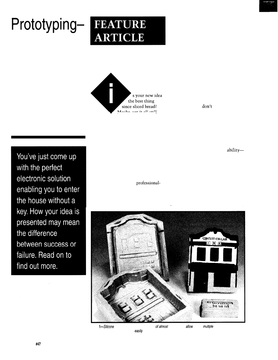
Beyond the
Electronics
and
Software
Dan Hopping
Maybe, yet it all still
seems to come down to the bottom
line: Can you sell it? How can a small
company or consultant be expected to
compete with those large, well-funded
design firms? Why is it that even the
best implementation of a great idea
seems impossible to sell to those with
the capital to fund it? If you represent
a small company, it is especially
important for your product to take on
that polished image look that big
company products have. And the best
part is that displaying a
looking product idea can be accom-
plished at a fraction of the cost it
takes most big corporations to build
prototypes. You can, using a little
ingenuity, produce very professional
results.
ALL GO AND NO SHOW DOESN’T
CUT IT EITHER
Over the years, I have noticed one
marked shortcoming that people with
wonderfully inventive minds [like
those who subscribe to
Circuit Cellar
INK)
have in common. Creative people
seem to suffer from the delusion that
everyone else in the world thinks as
they do. A common thread that most
of us, who pride ourselves in being
creative, have is the capability to look
past the obvious and envision the
possibilities. We
necessarily look
at what something is, but we try to see
what it might become. Think of it this
way: to the untrained observer, a
typical laboratory prototype appears, at
first glance, to be nothing more than
another jumble of wires, chips, screws,
and maybe an aluminum case. Some
people have an innate natural
while others of us have trained
ourselves-to look past the way things
appear and envision the many possible
applications it might have. If you don’t
hear anything else I say in this article,
please hear this: Don’t believe every-
one views the world the same way you
do, especially those who are good in
the business world. They have an
entirely different method of perceiving
Photo
rubber
molds
may be
made
any mode/ to
casting
polyurethane shells and
enclosures for project prototypes
and inexpensively.
34
Issue
June 1994
The Computer Applications Journal
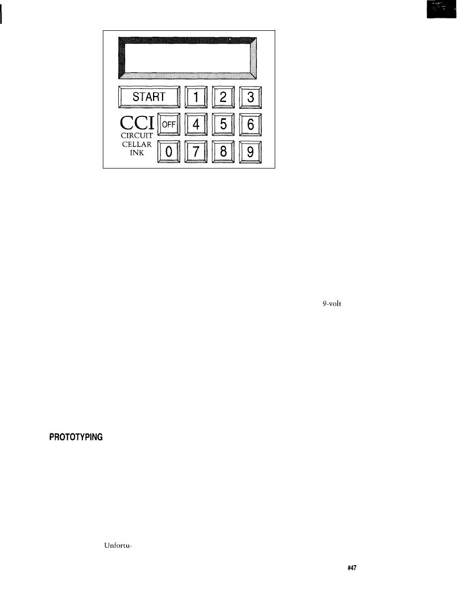
Figure l-Graphic artwork
for
creating a custom membrane
pane/ can be done using any
PC drawing program.
objectives, situations,
and other people.
That’s what makes
them good at what
they do [and rich to
boot).
I am sure you
have heard of all that
left brain/right brain
stuff. Believe it! If you
show many of them a
prototype made of
them on a tour of your idea in their
own world. Show them your idea (that
will, of course, make them even richer)
exactly as it might appear as a finished
product.
bent aluminum held together with
sheet metal screws, don’t be surprised
if you get a bit of a cold response and
more than a few blank stares. Your
goal, as someone trying to sell them
your idea, is to enter their world.
Don’t ask them to enter your world of
the laboratory and test bench. Escort
The biggest single advantage large
companies have over small companies
and garage shop operations is that big
companies have deep pockets when it
comes to making prototype evaluation
models that look exactly like the final
product. They spend many thousands
of dollars to make that first prototype
look like a finished “injection molded”
product, complete with custom
keypads, displays, and the like. It
really is the only way to evaluate a
product in the consumer world, and
large companies know it well.
tricks and a bit of common sense, you
can turn out a wonderful looking
prototype enclosure in short order and
at a very modest cost. My goal is to
give you the tools to allow you to take
your idea from an ugly [relatively
speaking) laboratory prototype to a
full-blown “custom” marketing
prototype.
nately, things like this tend to be
somewhat intimidating to those of us
who are electrodigitally bent, but that
need not be the case. Taken one step at
a time, it is actually quite simple.
Even those of us who are, how shall
we say, “artistically challenged” are
not without hope. Armed with a few
SUPER
A variant of this “finished prod-
uct” prototyping is not nearly as
complicated as you might imagine. It
actually lends itself to use by small
companies because it is far less
expensive than traditional approaches
such as Stereo Lithography. What
I
will attempt to explain in this article
are solutions that I have gleaned over
the years from some very creative
people I have worked with, augmented
by a few ideas of my own.
I believe the easiest way to show
you how to do this is to go through a
small product prototyping process step
by step. I will, however, go off on a few
tangents to cover important topics that
aren’t covered by my small example.
The product is going to be a small
scrolling alphanumeric LED advertis-
ing display assembled into a custom
enclosure. The display housing is
somewhat of an odd enclosure which
demonstrates that almost any form of
enclosure can be duplicated using
these techniques.
Because my emphasis is mainly on
prototyping for electronic projects, I
will not delve into the electronics of
this application. The intent of this
article has nothing to do with elec-
tronic systems design (which I dearly
love) but if all of you electroverts
manage to wade through this article, I
think you will be rewarded for your
diligence.
THE ADVENTURE BEGINS
The first thing we have to do is
spend some time defining product
requirements. When designing any
new product, either for yourself or
someone else, it is your job to make
sure the requirement specifications
really are complete. Our device
requirements will be somewhat
loosely defined because this is a
learning endeavor and it allows us the
flexibility to explore a few alternative
routes to meeting each requirement. A
typical requirements document might
have an entire chapter for each of the
following needs, but authoring
requirements documents is a bit
beyond the scope of this article.
PRODUCT REQUIREMENTS
1. A keypad that an average
customer can use to enter alphanu-
meric advertising messages (I have
included a separate keypad example).
2. An alphanumeric LED display
that presents a scrolling advertising
message.
3. The prototype must be capable
of operating from a typical 9-volt
battery (at least for a few hours) or an
unregulated
“wall wart” type
power supply.
4. The display must be able to
mount on the wall or stand on a
desktop with the message being visible
in either case.
5. The display will be contained in
a custom-molded enclosure that
allows a “theme,” as well as reduces
the final product cost (since we will, of
course, make and sell a million units,
right?).
6. Finally, a number of marketing
prototypes of the finished product will
be required.
THE BIG MARKETING QUESTION:
HOW WILL IT LOOK?
Big companies have the luxury of
investing lots of dollars in structured
market research. Most of us, of course,
cannot afford that indulgence. But, to
give your product the best chance of
success, you must spend some time
here. A great way I have found to get
ideas on how a new product might
look is to peruse catalog store show-
rooms or study consumer product
The Computer Applications Journal
Issue
June 1994
3 5

catalogs. Look closely at other compa-
nies’ product designs. Get into the
habit of asking yourself, “Why did
they do it that way?” I am always
amazed at the clever tricks I discover
just by closely examining other
people’s designs. Look closely at
everything from your toothbrush to
your car. File clever ideas away in a
notebook and you will soon start
generating your own ideas for the
future. Keep in mind that a small
plagiaristic bend in this area isn’t all
that bad. Why reinvent the wheel?
Many helpful ideas exist on expired
patents and they are free for the
taking. Work Smarter, Not Harder.
The beginning of the design is the
single best time to change the way
your product will look forever. Once
you start cutting material, it gets
harder to change with each cut. Work
at finding that right design before you
start. When you do find a product that
really says “WOW!” follow its lead. It
doesn’t even have to be the same kind
of product. What you want is for your
product to make a statement (usually
“buy me!“). Show it, or a picture of it,
to some of your nontechnical friends.
Does it say the same thing to them?
Don’t sell this part of the job short.
The buying public can’t see the hours
of effort put into the software, PC
board layout, microprocessor compo-
nent selection, and so forth. When you
unveil your masterpiece, the first thing
everyone will see is the front view of
the container your product is housed
in. Like those Head ‘n Shoulders
commercials tout-“First Impressions
Count.”
Assuming you have done your
homework, you now have some idea of
the style you want. Now comes what I
call the “shoehorn” portion of the
design. You have to fit all of your
components inside the proposed
container. If you have only small
components and a large enclosure, you
are home free. Usually the device must
be as small as possible, so this be-
comes somewhat of an iterative
process. Sometimes you can get away
with building a case, then laying out
your circuit boards around those
dimensions. When you aren’t sure
about your components fitting, then
Figure
use
ofphotographic negatives as
membrane panels
you to incorporate such
features as c/ear windows, dead front annunciators, and
colored logos.
lay out all of the required components
on graph paper in top, front, and
angle views. Then, using the final
overall dimensions, draw an isometric
perspective view of the box without all
of the insides.
You now have the minimum
package to design around. If there are
any odd-shaped components (e.g.,
relays, large capacitors, etc.), now is a
good time to give some real consider-
ation to their placement. Sometimes it
even makes sense to leave them off the
PC board. This usually increases
production costs, but might allow you
to get away with a smaller package.
Packaging size versus component
placement tradeoffs are sometimes
inevitable. Just remain aware of your
end goal and give more than one
layout some logical consideration.
ME, AN ARTIST? SURELY
YOU JEST
It’s
now time to draw a few
sketches to show what your product
might look like.
I used to think you had to be a
super artist to generate all those
beautiful proposal sketches used in
product demonstrations until I worked
on a design project along side a very
talented Industrial Designer. He was
able to sketch design after design
almost as quickly as we could think. I
even joined in the fun. I was produc-
tive within minutes. I was amazed at
the realistic-looking products I was
sketching almost effortlessly (I am by
no means an artist, either).
A roll of tracing paper and a few
markers are your next super
prototyping tools. Lay the tracing
paper over the isometric view of your
component layout (that you generated
earlier) and start drawing an enclosure
that will cover everything. Draw
doors, lines, knobs, dials, keypads,
displays, wherever they are needed,
using your isometric component
drawing as a guide. You only want to
sketch. Don’t worry about perfectly
straight lines. Right now you are just
thinking on paper.
If you have a design you are
“borrowing from, it is even easier. I
almost always use this approach. Place
the drawing of your original under the
tracing paper and trace the major
outlines of the existing product with a
heavy marker. Then include some of
the secondary lines with a thin
marker. One trick is to use a copy
machine to enlarge small catalog
pictures to a good working size which
can be used as your initial tracing
master. Use this master as a stepping
stone to draw a “first pass” at your
new product. This way it’s all a matter
of being able to trace, and even I can
do that.
With each revision, trace most of
the original lines only changing a
small portion of the design. I like to
change the drawing I am using as a
master often, using the last iteration as
the new master. This allows the design
to evolve naturally. The trick is to
only change a little bit each time so
you don’t have to spend time dimen-
sioning each new sketch. Strangely
enough, the final design often looks
nothing like the original. What the
original product design provides for
you is something other than a blank
piece of paper to start from, and
starting is always the hardest part.
You will be amazed at just how
easy this technique is. It’s the method
36
Issue
June 1994
The Computer Applications Journal

Dome Switch
Scotch Tape
Membrane Panel
all connections
Vector Prototyping Board
with plate through holes
Figure
for creating full custom membrane switch panels is to use dome switches attached to
doubled-sided plated
most professional industrial designers
use. Once you have a few good
sketches, show them to your friends
again. When you decide on the final
design, you may or may not want to
get a professional rendering done. Use
good judgment here. If you are trying
for supplemental venture capital, then
it’s probably a good investment. If not,
often just coloring a Xerox copy of
your final sketch can create quite a
striking piece of artwork.
brane panel can be highlighted with
accenting colors that match the case.
A dark background provides good
contrast for characters, lines, graphics,
and so forth. It also allows you to get
away with some neat tricks like “dead
front” annunciators. Each of the first
methods I will discuss will end up
with color graphics on a black back-
ground.
CUSTOM MEMBRANE PANELS
One of the easiest ways to make a
plain, off-the-shelf, metal or plastic
enclosure look like a customized
product is to add a custom membrane
panel. A nice example of this was
presented by Sanjaya Vatuk in his
EPROM Emulator article
(Circuit
Cellar
INK,
Issue
There are
differing levels of complexity available
here. From a simple panel with your
company logo and a few LED identifi-
ers on it all the way up to full-color
graphic panels with membrane keys,
displays, and dead front annunciators. I
will discuss membrane keypads and
deadfront annunciators later, so I’ll
start with the prototype membrane
itself. I will present three levels of cost
and complexity so you can choose the
most appropriate application for your
need.
Let’s talk about some methods of
making membrane panels. I generally
use black for my membrane panel
backgrounds. Two very good reasons
for this are film negatives and copier
toner are both usually black. Black
also goes with (or at least doesn’t clash
with) any color scheme. The
There are a couple of ways to
generate the original artwork. The
easiest way is to draw the front-panel
graphics using a computer graphics
drawing program such as Core1 Draw
(see Figure 1). When you have the
artwork complete, simply reverse the
black and white so the letters and lines
appear white and the background
appears black. Print this using a laser
printer with good black toner onto a
piece of clear overhead transparency
film instead of paper. You now have a
black background with clear letters
and lines. This will actually become
the base for your membrane panel. It is
now a simple matter of masking off
the appropriate areas from the back of
the panel and spray painting the
desired color from behind. The color
shows through only where the panel
was clear. You can make graphics,
letters, and names any colors you
choose. To make translucent windows
(LED or lamp indicators), just rub
some translucent “Zip-a-tone color
rub-on film” onto the back of the clear
indicator area. Zip-a-tone makes a
wide variety of colors in varying
capacities.
If the membrane panel will see
more than just prototype use, it is a
good idea to mirror image of the
original artwork with your graphics
program. This way the toner ends up
on the back side of the film where
fingers won’t touch it during use. If
you choose not to reverse the image,
printing it toner side out requires a few
coats of spray polyurethane for
durability. If applied in a few light
“dusting” coats, the polyurethane
gives your membrane panel a very nice
textured look as well as protecting it
from the elements. If you have any
areas in your panel that you want left
clear, such as panel meter fronts, be
sure to mask these areas before you
texture with the polyurethane.
If you don’t have access to a
computer with a good laser printer, all
is not lost. You can always paste up
the artwork by hand. Trust me, it’s
easier than it sounds. Start with a
sheet of good-quality black paper
which you can get from an art supply
store. Using white Zip-a-tone rub-on
lines and letters, generate the
on-black artwork for the original. Copy
the artwork onto an overhead transpar-
ency using a good copy machine. The
rest of the process is identical to that
above. Although I have never used one,
I hear there are some copy machines
that will invert black and white,
allowing you to use a regular
white original.
A much better, although a little
more expensive, membrane panel can
be produced by using film negative.
One advantage is that the artwork is
easier to produce if you are using a
hand-generated rather than
generated original because you use
standard black-on-white rub-ons and
paste-ups instead of the
black normally required using a copier.
When your original is complete. take
your artwork to a commercial photo
house like the places that do PC board
artwork filming. Get a negative shot
with the emulsion on the backside of
the film. This gives you essentially the
same thing as the transparency, but
the black is absolutely opaque, which
means back lighting will not show
through and the graphic and charac-
ters’ edges are much more defined (see
Figure 2). For the ten dollars or so it
costs for the negative, it is usually
worth the extra to use film. I use this
The Computer Applications Journal
Issue
June 1994
37
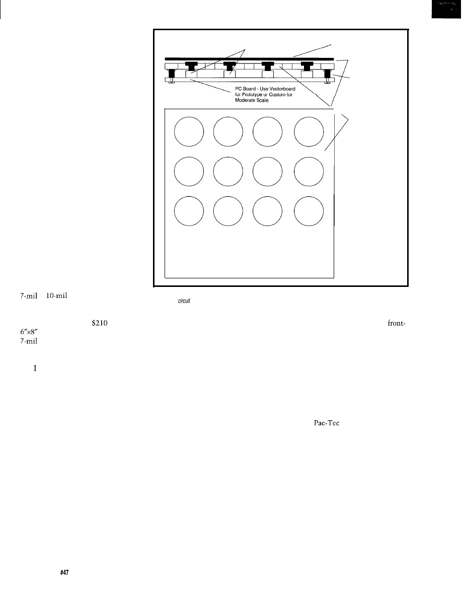
method whenever I have backlit
displays.
One very advanced looking feature
you may want to add to your mem-
brane panel product is called a “dead
front” annunciator. During normal
operating conditions, the alarm
message is invisible, appearing as a
part of the normal black background
until some alarm is detected. At this
point, it is backlit with a lamp to show
a predefined text message announcing
the condition (see Figure 2). A trick to
help you effectively produce a dead
front annunciator is to keep the
transparent alarm message text as thin
as possible. Also use a dark (red works
best) Zip-a-tone translucent rub-on and
affix it the back side of the panel
behind the message. This will hide the
words when they are not backlit. You
can help make the unlit characters
disappear by adding some “texture” to
the front panel, as discussed above,
using the spray polyurethane.
One final method that makes
beautiful color panels is to generate
layer drawings for each color and have
the colors silk-screened onto a piece of
or
polyester or
polycarbonite film. The final results
look wonderful, but you will pay. The
last job I had done ran
for ten
three-color membrane panels on
polyester.
ADDING KEYBOARDS
have outlined a few ways to
produce membrane panels. Now let’s
give them some life by adding func-
tional membrane key switches.
Custom integrated membrane keypads
are very inexpensive in large quantities
(not surprising) and have many
advantages over discrete component
keyboards. What you may find surpris-
ing is that they can also be relatively
inexpensive and easy to produce in
small and moderate, quantities. If
designed properly, they can easily be
transitioned to an integrated custom
membrane keypad when your project
hits the big time.
Membrane keypads consist of two
basic sections. First is the overlay or
membrane panel with the graphic
outlines of keys on it which we have
just discussed how to make. The other
Momentary Contact Switches
(PC Board Mount)
Membrane Panel
Production
Spray Adhesive
PC Board Mounting
Studs (epoxy mounted)
Drilled Panel or
Enclosure for
Mounting Membrane
Panel
Figure
4-PC board-mount
momentary contact switches can
be used to create
membrane
switch
panels right on
your system
board.
is the electromechanical switch itself.
So let’s go through the steps to create
the functional switches that will be
located under the graphic overlay and
integrate the two portions into a
functional custom keypad.
I normally use 0.1” grid tracing
paper to lay out the membrane overlay
in pencil. When I have finished
positioning the keys where I think
they will fit best, I ink over the pencil
lines with an indelible marker. With
the key positions now defined, you can
use this paper mockup of the keypad
to see if it fits well on your enclosure.
If everything looks good, you can use
the paper overlays as a guide to locate
the dome switch positions on the
prototype perfboard.
Normally this paper keyboard
overlay will become my functioning
front panel during the remainder of the
electronics development (sort of a
prototype of the final prototype). As I
near the end of the development
process and I begin to feel confident
that I haven’t forgotten a key or
display indicator, only then am I ready
to do a final photo or silk screen
panel graphic overlay.
Using the following simple
techniques, you can have as few or as
many functional keys as you want.
The best part is you can locate the key
switches anywhere you want on your
display panel. Even if you decide that
the custom-molded enclosures I will
present later are too difficult or time
consuming, you can still make an
ordinary
style enclosure look
like a custom box by adding a custom
overlay with membrane key switches.
There are quite a few ways to
inexpensively create custom key-
boards, but my favorite is to use
individual dome switches mounted
over PC board copper traces. Actuating
the dome with your finger provides a
switch closure by shorting the traces,
thus completing the circuit (see Figure
3). I like this method for a number of
reasons. Dome switches provide you
with a defined click for tactile feed-
back of each keypress. You can have as
38
Issue
June 1994
The Computer Applications Journal
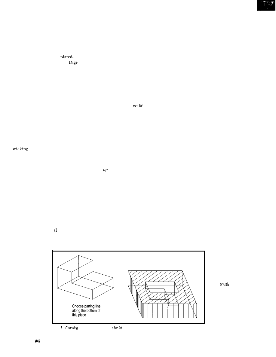
many key switches as needed and they
can be located any place you desire.
Membrane keypads are inherently
water resistant and therefore easy to
clean.
To make a prototype “custom”
keypad, use 0.1” center double-sided
prototype perfboard with
through holes (available from
Key). Locate the dome center over a
single pad. The edges of the stainless
steel dome will then make contact
with some of the adjacent pads. Since
the perfboard has plated-through holes,
tack soldering leads to the back side of
these pads creates a functional proto-
type key switch. To accomplish this,
tack solder 30-gauge wires onto the
back of the appropriate plated-through
perfboard holes as shown in Figure 3.
Make sure the solder does not wick up
through any of the holes and cause a
solder bubble under the dome switch.
If you have trouble with the solder
through, your soldering iron is
probably too hot. Try heat sinking the
switch side of the pad with aluminum
foil. You might try rubbing a bar of
soap against the dome switch side to
fill the holes with soap before you
solder. If you do soap it, be sure to
wash the soap off thoroughly before
you mount the dome switches.
With all of the switches mounted
in their proper locations, you can now
finish the keyboard by covering it with
a custom membrane panel. To accom-
plish this, spray the PC board and the
backside of the overlay membrane
with a spray adhesive have actually
used rubber cement in a pinch). When
you spray the back of the membrane,
remember to
mask any areas
you want left
clear for displays
or meter move-
ments so they
will clearly show
behind the
display panel.
Position the
graphic overlay
correctly over the
switches and
displays. Press
the two pieces
there you have it: a custom membrane
keypad complete with graphics.
Another way to make a quick
custom keyboard is to use a surplus
membrane keypad from an existing
product as the functional keys. Often
times you can find them at local
electronic surplus stores or in surplus
catalogs. When designing your custom
membrane overlay, locate each key
graphic directly over an existing key
on the surplus keypad. You may not
need to use all of the existing keys.
Glue your custom membrane panel
over the surplus keypad. Run the
output of the surplus keypad to your
decoder circuitry and
You now
have a quick “custom” keypad.
Here’s yet another super keypad
idea. This one I inherited from a friend
at work. This one works well if your
enclosure has a flat surface with room
to mount a PC board directly under-
neath using standoffs. Drill holes in
the case corresponding to your key
positions on your custom overlay,
large enough that the actuator buttons
of a micro switch fit through with
about clearance on each side.
Mount the switches on a piece of
perfboard, then mount the perfboard
with standoffs so the switches just
peek (about 0.02”) above the holes in
the case as shown in Figure 4. Glue
your custom overlay to the case such
that the switches are aligned properly
with your graphic and you have a great
tactile feedback keyboard. Be sure to
affix the standoffs securely as you will
be pressing against them with each
keypress. You can easily transition
this method into low-to-moderate
volume production by designing a
A fancy twist you may want to
add to your membrane keyboard is
custom PC board for the switches.
now possible because of a new product
by Interlink Electronics called Force
Sensing Resistors. They are membrane
keys that change resistance as force is
applied to them. These neat little
gadgets can be used for a variety of
applications. I like the idea of having a
variable-speed scroll on a display. If I
want it to scroll faster, I just press a
little harder. To slow the scroll down,
just release some pressure. Four of
these could be used together to form a
flat membrane “mouse” controller for
cursor positioning on a CRT display.
CUSTOM PROTOTYPE
ENCLOSURES
The last area of Super Prototyping
I want to share with you is actually
constructing custom prototype
enclosures. An entire book could be
written about this subject, but I don’t
know of one that exists. If you do,
please share it with the rest of us on
the Circuit Cellar BBS. Depending on
the intended use of your prototype,
there are either one or two major steps
to construction. If you only need a
great-looking prototype (i.e., you will
always be there to tell people “careful,
it is only a prototype”), you can get
away with a lot less robust enclosure
than if you intend to let a customer
use the prototype on his own. Some-
times you must let customers use
prototypes for marketing and/or
product development. Often when this
is the case, you need a few very sturdy
prototypes
This allows for a single
piece mold as shown.
together and
Figure
parting lines carefully can
you
get away with
a sing/e-piece mold.
4 0
Issue
June 1994
The Computer Applications Journal
(sometimes 20 or
30) that are
exactly the same.
The problem is
that you probably
are not ready to
drop
or
more to make a
custom mold yet.
After all, the
reason you need
the prototypes is
to see if your
product is really
ready for the big

time. So what’s a designer to do? Since
you will have to construct at least one
enclosure no matter what, let’s address
the single prototype solution first.
I like this more than any other
facet of prototyping since this is the
area that takes the most creativity.
Your goal is to make a single
looking enclosure that will hold up to
at least a minimum of abuse. Here are
a few tricks that may help you Don’t
be afraid to develop a few of your own.
Remember-creativity is the rule.
The easiest is to “borrow” from
other enclosures. You might take part
of an enclosure used to house a toaster
and part of another used to enclose a
computer front panel and glue them
together to create a new custom
enclosure for your product. Drill and
cut new holes as needed. You may also
want to epoxy standoffs to mount the
PC boards and components. A little
filler at the seams and a fresh coat of
paint will typically produce a
looking enclosure.
A Dremel tool with an assortment
of bits is an indispensable aid during
this portion of your project. A few
other tools I find handy to have around
are an assortment of Xacto knives,
assorted glues, tapes, clay, automobile
body puddy, files, sandpaper, coping
saw, band saw, and a dedicated
vacuum cleaner for the mess. You
don’t want to give the wife’s new
Kirby back to her with model paint
and glue all over it. There are lots of
other tools you may want to add to
your own prototyping library. Be
resourceful, but if you do need your
wife’s only Rubbermaid spatula at 3:00
A
.
M
.,
be courteous (if not intelligent)
and replace it first chance you get.
If there is nothing available to use
as a master and you do have to create
your own from scratch, a trip to your
local professional modeler isn’t your
only hope. There is a great prototyping
medium that architects use to create
very intricate building fronts for their
presentation models. It’s called
MFP, or Balsafoam. The
stuff is very dimensionally stable,
nontoxic, and can be shaped and
formed with almost anything.
A product that can be used for
models that require a higher degree of
structural integrity is called Sentra. As
far as I can tell, it appears to be a very
low density polyvinylchloride (plastic
plumbing pipes are made of PVC). It
solvent bonds quickly and is relatively
easy to cut and sand. Curved edges can
be routed out of thick pieces or from
built-up layers. It has about the same
weight and characteristics as struc-
tural foam, so it’s a good choice if you
are prototyping large items.
Finally, you might get away with
using a portion of an existing product
and gluing custom pieces of Balsafoam
or Sentra where required. Remember,
paint and putty can make any number
of joints look seamless.
WHEN ONE IS JUST NOT
ENOUGH
So, you
now have some ideas of
how you might construct a single
prototype enclosure. But what do you
do if you need more? Easy, just make a
bunch of exact copies of the original
you have just constructed (yeah,
right!). You could have a steel molding
tool cut if you owned sufficient equity
in your house and didn’t mind hocking
it, or you could try the following: I will
detail one of the most common
methods used by professional proto-
type houses to duplicate low volumes
of an original item. In the industry it’s
called a “rubber mold.” It is not all
that difficult-and actually quite
to create molds using a special form of
silicone rubber and the techniques I
will discuss.
There are quite a number of room
temperature vulcanizing
silicone rubber mold-making materials
available, but the one that I would
recommend you use, at least until you
get used to working with them, is Dow
Corning RTV Silicone Rubber
110.
This comes in two parts: the liquid
silicone rubber and the catalyst.
Although it is not as strong as the
other silicone rubber mold materials
that Dow offers, the RTV
110 can
be
cast fairly reliably without the require-
ment of a vacuum chamber. Vacuum
chambers that can pull a vacuum of
about 29 inches of mercury are
required by most other mold com-
pounds typically used to degas the
rubber so tiny air bubbles don’t form
on the face of the rubber mold. The
two-part compound is mixed and
poured over your original model or
pattern. The low viscosity and high
creep of this material allow it to get in
between even the smallest of cracks.
To actually cast a part, you must
first analyze the possible places where
a parting line should be located (Figure
5). Things to consider are how will this
allow the mold to be removed from the
part, where will you locate the fill hole
and air vents so the molding material
can be poured into the completed
mold, and how might the parting line
affect the appearance of the part?
Putting a little extra effort into this
one step will help you immensely in
some of the other steps.
For this advertising display
project, I am going to make a
piece mold. First we need to build a
container, or dam, around our master.
This will retain the excess rubber
molding material. Seal around the
edges of the master using wax or an
inhibitor-free modeling clay. If there
are any small holes, fill them also with
clay; these can be drilled as a second-
ary operation later. Paint the entire
inside of the box and the face master
enclosure with a mold-release agent
using a small artist paintbrush.
Next, mix the silicone rubber with
the catalyst using a hard rubber
spatula. Make sure there is no un-
mixed material in the corners of the
container you are using. The RTV
compound will be a uniform color
when mixing is complete. Place the
pattern and the mold box on a level
surface. When positioning the master,
make sure it is oriented in such a way
that no air bubbles or air pockets can
be trapped. It is a good idea to brush a
coat of the liquid mold material over
any intricate areas of the master to
make sure no air bubbles form. Then
pour the rest of the liquid RTV into
the mold casing. It is a good rule of
thumb to pour enough RTV to leave at
least
of extra RTV over the highest
point of the master.
After the rubber has cured, which
typically takes one day, remove the
dam or the mold box. If this were a
one-sided mold, you could remove the
master from the mold now. However,
42
Issue
June 1994
The Computer Applications Journal
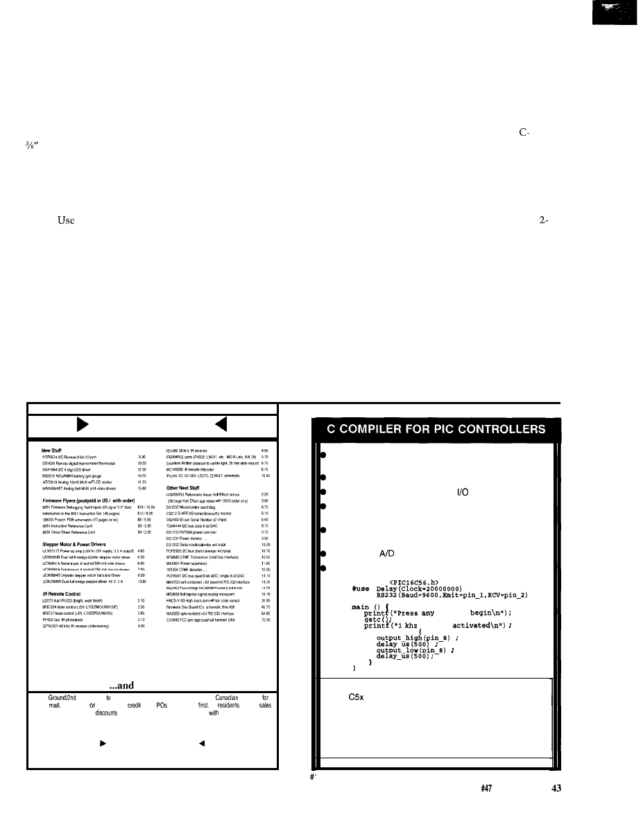
since this project requires a two-piece
mold, do not remove the rubber from
the master yet since it may not be
possible to replace it precisely back
into the mold.
Now invert the box and build
another square dam around the back
side of the part, again making a mark
from the highest point on this side
of the piece. You may also want to cut
a couple of locating keys into the
cured rubber surface to aid in the
alignment when you are putting it
together to actually cast prototype
pieces.
either a circular piece of
clay or rubber tubing to make a fill
hole so you can pour the molding
plastic into the mold after it is com-
pleted.
With the sprue hole of the master
located correctly, again build a dam or
box retainer and seal any joints that
are left with modeling clay. Apply a
coat of mold release over the entire
surface. Repeat the steps to mix the
catalyst with RTV rubber then pour it
in as before. After the RTV has cured,
you may disassemble the box and
remove the mold from the master.
When removing the master from the
mold, never take the master (or
product] out from the mold; instead,
slowly peel the mold away from the
master. If you try to remove the
model from the mold it may cause the
rubber to rip. Go slowly, especially if
it is an intricate model. If all went
well, congratulations are in order:
you now have a two-part mold for
your product and you still own your
house.
YOU
can now make quite a few
polyurethane parts identical to the
master, only much stronger. The new
cast pieces will be one solid piece of
polyurethane plastic, which is pretty
tough stuff. One quick-set urethane is
called Alumilite made by the
Alumilite Corporation. It sets up in
about three minutes, so it is important
that you are set up and ready to go
before you start. Because this polyure-
thane sets up so quickly, it is only
appropriate for smaller molds that do
not have a lot of intricate areas to fill.
Ciba-Geigy’s Formulated Systems
Group makes some overnight cure
plastics for producing some very large
and intricate models.
To actually cast a urethane part,
you lightly clamp the two halves of
the mold together. I like to hold the
two rubber mold pieces together with
two pieces of wood and some
clamps, but rubber bands work well
also. This holds the mold firmly in
position and, as long as you don’t put
too much pressure on the clamps, will
not distort it. Place a funnel into the
sprue hole so you can pour the mold-
ing material in quickly. Using the
part Alumilite, mix part A into part B
and stir vigorously for 2030 seconds
until the Alumilite is uniform in color.
With the mold in a vertical position,
quickly pour the Alumilite into the
sprue hole until in comes up out of the
air vent hole. It helps to have a small
vibrator (an aquarium filter pump
works well) or someone to tap the
mold gently as you are pouring to get
any air bubbles out of the mold and to
make sure the Alumilite gets into all
the crevices and cracks.
Project
Part5
much more...
UPS
day $6.5019 48 US states, COD add $4.50. PO Boxes and
orders $6
USPS
Check, MO, COD only, no
cards.
add $50. call
NC
add 6%
tax. Quantity
start at five parts. Data sheets included
all parts
Call/write/fax for serious/y tempting catalog...
Pure Unobtainium
Your
unusual parts source
13109 Old Creedmoor Road
l
Raleigh, NC 27613
FAX/voice (91916764525
Integrated software development environment including an
editor with interactive error detection/correction.
Access to all hardware features from C.
Includes libraries for RS232 serial
and precision delays,
Efficient function invocation mechanism allowing call trees
deeper than the hardware stack.
Special built-in features such as bit variables optimized to
take advantage of unique hardware capabilities.
Interrupt and
built-in functions for the C71.
Easy to use high level constructs:
#include
# u s e
key to
signal
while (TRUE)
compiler $99
2 day shipping
$5
C71 compiler $99
Next day shipping $12
COD additional $5
CCS, PO Box 11191, Milwaukee WI 53211
414-78 l-2794 x30
The Computer Applications Journal
Issue
June 1994

Wait about ten minutes. After the
Alumilite has cured, remove the mold
from the part and cut off any runners
and spurs. Sand any rough edges and
remaining spurs which might appear
around the parting lines. If done
correctly, you will have an exact
replica of your original piece. It can be
painted, drilled, or machined. Almost
anything you can do with thermoplas-
tics you can do with the new part.
Urethane has high impact resistance
and good thermal resistance.
With 3 1
rubber molds, you
can usually make 10 to 15 models
before the mold starts to deteriorate or
rip. You can also fix small rips in the
mold using some Sylastic 732-RTV
adhesive sealant. More detailed
information on the polyurethane
plastics can be obtained from
Geigy or Alumilite. Additional
information on mold materials as well
as step-by-step instructions on how to
create molds can be obtained from
Dow Corning.
Well, there you have it. Now all
that remains is to paint your master-
piece, put it together with your new
membrane panel or keyboard, stuff it
full of electronics, and head for the
trade show.
Dan Hopping has been doing medical
device product development for the
past 12 years. He also owns a video
production company that specializes
in “How-To” videos. He may be
reached at
or
407
Very Useful
408 Moderately Useful
409 Not Useful
Rubber stamp making equipment
or photo cure polymers
Grantham’s
418 Central Ave. N.E.
East Grand Forks, MN 56721
(218)
Sintra [foamed, closed cell PVC
sheets), Fome-Cor and Formable
Fome-Cor, and many other foam
center prototyping materials
Fomebords Co.
6750 Jones Mill Ct. N.W.
Norcross, GA 30092
(404)
for information
(800) 362-6267 for sales
3-minute cure modeling plastic,
rubber mold-making supplies
Alumilite
225 Parsons St.
Kalamazoo, MI 49007
(616) 342-1259
Silicone mold-making supplies
Dow Corning
Regional Sales Office
Atlanta, GA
(404) 751-7979
Polyurethane resins for molded
parts
REN Plastics
Ciba-Geigy Corp.
49 17 Dawn Ave.
East Lansing, MI 48823
(800)
Cook Composites Polymers
2 17 Freeman Dr.
P.O. Box 996
Port Washington, WI 53074
(414) 284-5541
P.D.L.
212 West Taft Ave.
Orange, CA 92665
(714)
Dimensionally stable cement and
U.S. Gypsum Products
101 South
Dr.
Chicago, IL 60606
(3 12) 606-4000
Mold release coatings
National Engineering
Products, Inc.
5110 Ridgefield Rd., Ste. 411
Bethesda, MD 208 16
(301) 656-1688
Mold barrier coatings
Dexter Corp.
Hysol Division, Frekote Products
One Dexter Dr.
Seabrook, NH 03874
(603) 474-5541
Plastics
P.O. Box 855
Woodside, NY 11377
(718) 672-8300
Vacuum chambers and pumps
Ace Glass, Inc.
P.O. Box 688
1430 Northwest Blvd.
Vineland, NJ 08360
(609) 692-3333
Modeling clay for RTV rubber molds,
Permaplast X28, X29, and X30
American Art Clay Co.
4717 West 16th St.
Indianapolis, IN 46222
(317) 244-6871
Snap dome switches
Square-D Co.
Data Entry Products Division
302 3rd St. SE.
Loveland, CO 80537
(303) 663-7337
Dimensionally stable modeling
material, lexathane, balsa foam
Jiffy Foam, Inc.
P.O. Box 3609
221 Third St.
Newport, RI 02840
(401)
Laser printer specialties
Inc.
Riddle Pond Rd.
West
VT 05086
(800) 252-2599
Color decals
Systems
3535 Stillmeadow La.
Lancaster, CA 93536
(805) 943-4746
44
Issue
June 1994
The Computer Applications Journal

Habitech94
The Home
Automation
Industry’s
Own Trade
show
Ken Davidson
involved in or
closely follows the
industry knows, Habitech is virtually
the only industry trade show designed
specifically for the home automation
arena. Only in its second year,
Habitech94 (held April 13-16) was a
resounding success.
Parks of
Parks Associates makes it her business
to know the home automation
industry, so it’s only natural that her
firm would sponsor the show. I
represented Circuit Cellar Inc. and the
Computer
at
both shows, so let me give you a taste
of this year’s shindig and what new
products the players had to offer.
BIGGER AND BETTER
Experience is a great teacher, and
judging by the improvements over last
year’s show, Parks is a quick learner.
Last year the exhibits ran four full days
and the seminars overlapped the
exhibit hours. Exhibitors chained to
their booths ended up missing the
talks and classes, plus the show floor
was deathly quiet during much of the
show. This year, though, the seminars
ran primarily in the morning during
four days, while the exhibits were
confined to just the afternoon and to
just three days.
One other key difference was that
last year, two of the show days were
for trade only while the other two
were for consumers as well. It’s rather
difficult to tailor show material to
both trade and consumers, so this year
the show was confined to just trade.
Held at Dallas’s Infomart
tacular in and of itself), the show floor
this year was twice the size of last
year’s, and the displays were bigger
and better than ever.
CEBUS
One of the big marketing points of
the show was the promise of a CEBus
pavilion, replete with companies
offering
products.
I’ll cut right to the chase and start
with the pavilion.
In the center of the pavilion was a
small house mockup, including a front
door, living room, bedroom, and utility
room. Packed with equipment from
several different and independent
companies, a rather fake-sounding
narrator (wielding cue cards) guided
the showgoers through an average day
in the CEBus house. It wasn’t quite as
complete as the Bright Home (see
“Take a Tour of the Bright Home,”
issue
but effective just the same. A
key point of the exhibit was that the
devices being shown were produced by
different companies, were using real
CEBus interfaces, and all talked with
one another.
Surrounding the house were
booths for the companies showing
products in the pavilion, including
Panasonic (TV, VCR, laserdisc, CD
player, receiver), Ademco (security
system),
(lighting control
system), Trane (HVAC), and US
(wiring and wall plates). Other compa-
nies with
products
included Intellon (power line and RF
Photo l-cabling
and
plate
offerings from US
are ideal for
prewire
installations. The wire
bundle includes two coax cab/es and four Level 3
fwisfed pairs. The
plate accomodafes a standard
AC outlet,
fwo coax cab/es, and an
connector.
4 6
Issue
June 1994
The Computer Applications Journal
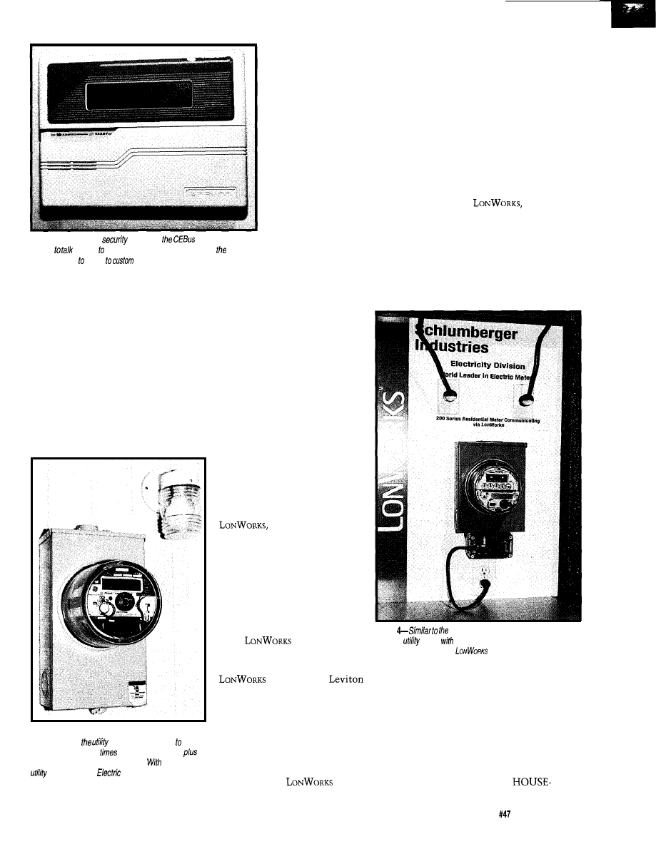
without having resort
or special interfaces.
interface products), The Training
Department (offering CEBus classes),
Diablo Research (custom development
services), and the CEBus Industry
Council (charged with publicity and
conformance testing). General Electric
also had a service entrance meter set
up, but it wasn’t talking to the rest of
the pavilion.
Intellon was showing Decora-style
CEBus wall switches that should
appear shortly at a price well under
$100 and within a year should be
competitive with Leviton’s
X-10 wall switches. My
own guess was that such
switches would initially
show up at around $150, so
I was pleasantly surprised.
They also had companion
plug-in control modules
that can be used in a
manner similar to X-10
modules.
Photo
2-The Ademco
sysfem in
pavilion used
CEBus
directly lights, drapes, and other devices in
house
All the companies
showing products except
Panasonic are either in
production right now or
will be shortly. Panasonic,
unfortunately, was only
testing the waters with
prototypes and has no plans right now
Photo
3-Power line communications is being pursued
very actively by
companies as a way effect
load shedding during
ofpeakpower usage
do automated remote meter reading.
their CEBus
meter, Genera/
was one of fhe first to
incorporate a CEBus interface in a production device.
for production units. Apparently those
While most of the products were
talking to each other, there was no
orchestrated demo for the masses
passing through, so unless you were
“fortunate” enough to be personally
ushered through, it was difficult to see
how things worked together.
SMART HOUSE
While SMART HOUSE may have
hit the ground running, and its
development has been active longer
than CEBus or
it certainly
wasn’t well represented. AMP had a
full-size truck trailer tucked in one
corner of the exhibition hall contain-
ing some SMART HOUSE equipment,
but you had to be lucky enough to
time your visit just right to be brought
through the trailer by a tour guide The
in a position to give the green
light need to see some evidence
of high-volume potential, so, at
least for the short term, it’s an
up-hill battle.
Things are finally looking
up for a CEBus home, though
we still have a wait before we
see lots of products that are
reasonably priced. At least some
products are finally into
production.
LONWORKS
While we’re talking about
communications systems, we
have to include Echelon’s
the prime contender
facing off against CEBus for the,
home’s communications
backbone. Sporting a rather
impressive carpentry and paint
job, the Echelon “pavilion”
included individual kiosks
displaying the wares of
14
companies that have incorpo-
rated
in their
products.
Schlumberger showed a
Photo
GE meter in Photo 3, Schlumberger a/so
makes a
meter
a power line communications interface,
though they
chose to use
rather than
CEBus.
utility meter;
had
lights, switches, and motion detectors;
Residential Control Systems (RCS)
makes thermostats; Thomson Con-
sumer Electronics showed a television;
Silverthorn showed a voice annuncia-
tor; and Toshiba and Motorola were
showing their neuron chips, which are
the core of any
design.
casual passerby didn’t have much to
look at. Our booth was just down the
aisle from the trailer, yet I couldn’t
seem to happen by at the right time
during any of the three days the show
floor was open to get inside the
behemoth.
Lennox, the HVAC people, were
also showing a SMART
The Computer Applications Journal
Issue
June 1994
47
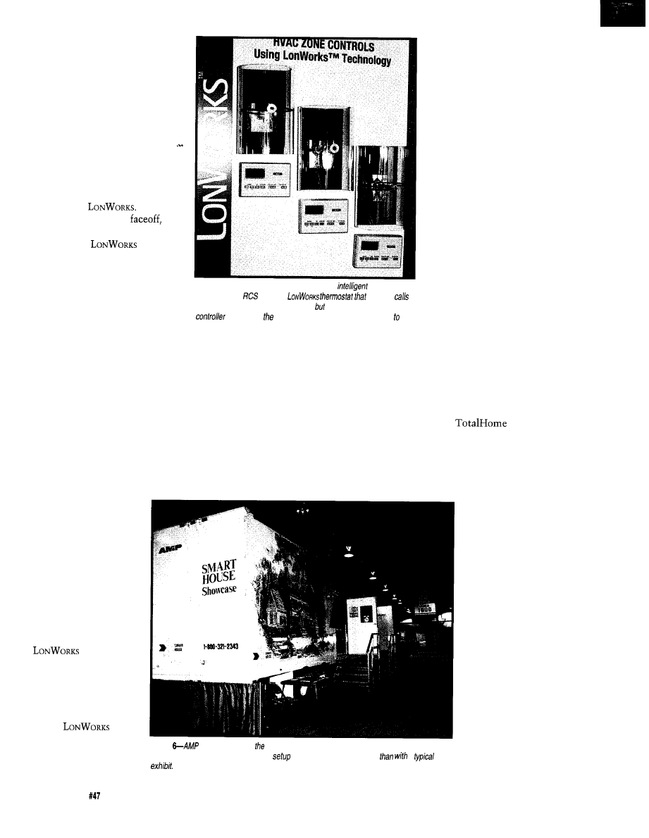
compatible environmental
control system. No other
SMART HOUSE manufacturers
were at the show, however.
PERSONAL ASSESSMENT
The natural question out of
everybody’s mouth is, “Which
standard is going to ‘win’!” I tend
to agree with the sentiments of
one of the seminar leaders. I
don’t think you’ll see a clear
winner of the battle between
CEBus and
Rather
than a VHS/Betamax
I
think you’ll see an Apple/IBM
coexistence.
is
fantastic at doing purely control
tasks in an industrial setting.
However, its biggest downfall is
its lack of provision to allow
information distribution
throughout the house. Here,
since it was designed specifically
Photo 5-A
thermostat is a natural for a more
communica-
tions interface.
makes a
not on/y
for heat or cooling at fhe proper times, a/so allows a central
fo query for current femperafure and sefpoinfs and
change those sefpoinfs.
just too expensive and, in the
long run, won’t be supported by
enough manufacturers.
PRODUCTS FOR THE REST
OF US
Communications standards
may be fine for some high-end
products just starting to hit the
market, but what about the rest
of us who want to automate
now? There was no lack of
products being shown to fill the
bill.
Starting at the high end,
AMX, Interior Systems Design,
and a few others were showing
their custom whole-house
solutions aimed primarily at
houses in the $1+ million range.
While their displays were quite
impressive, and it’s always fun to
dream, these systems just aren’t
for the common man. Each
for home control, CEBus has the edge.
Any audio or video device made by one
manufacturer can send data to a device
made by another because the standard
covers data channels in addition to
control. Echelon’s answer to the data
question was that you could come up
with your own scheme, but that
doesn’t help the interoperability issue.
companies decided they didn’t want to
be involved in a battle of the stan-
dards, so developed the same product
twice, once using each standard. They
leave it up to the utilities who will be
buying the system to decide which
they want to use. Free enterprise in
action.
company custom configures the
system for each client (or provides
extensive training for installers), so
they aren’t aimed at end user installa-
tions by any means.
Some of the larger companies
aren’t jumping in bed with one or the
other, either. While in the Echelon
booth, I was shown a
diagram detailing a
system developed by
Honeywell and FPN
(First Pacific Networks)
to allow utilities to
communicate with
devices in the house for
energy management
purposes. The Echelon
rep was only too happy
to point out the use of
in the setup.
A little later, while at
the Intellon booth in
the CEBus pavilion, I
saw exactly the same
diagram, though now
all the
references were
replaced by CEBus.
As I’ve always contended, SMART
HOUSE is fine for new construction in
a limited number of circumstances,
but for the average homeowner, it’s
One step down in price is the
Honeywell
system. While
not new, they are continually working
on adding new options to the system.
Since Honeywell already has a whole
network of sales representatives, they
rely on that network for sales and
Apparently, the
Photo
makes spreading SMART HOUSE gospel easier with their portable show
house. Their approach certainly makes
and breakdown much faster
a
50
Issue
June 1994
The Computer Applications Journal
installation support.
Again, not the system
for the do-it-yourselfer.
Rounding out the
whole-house control
systems and bringing up
the lower end include
offerings from Home
Automation Inc., whose
somewhat dated system
concentrates mostly on
security functions but
can also do some home
control; the Integrated
Control System (ICS)
from Off The Shelf,
which tries to integrate
separate subsystems
located throughout the
house [though they will
sell only to dealers); a
new offering from an

Australian company called Jeeves,
which handles direct inputs, direct
outputs, analog, optional X-IO, and a
PC interface; and finally Circuit
Cellar’s
2000, which
consists of the original HCS II core
components combined onto a single
board and packaged in a steel enclo-
sure for the dealer/installer market.
The main controller includes 24 digital
inputs, 24 digital outputs, 8 analog
inputs with selectable gain, two-way
X-10 interface, telephone interface,
expansion connectors, plus support for
all the HCS in-house network modules
and the XPRESS programming lan-
guage.
PARTIAL SOLUTIONS
Most of the rest of the exhibitors
were showing independent subsystems
designed to perform a specific kind of
control in the house. The audio/video
guys were present in force, sporting all
kinds of methods for distributing A/V
signals and their companion controls
throughout the house for the ultimate
in home entertainment. A booming
stereo demo wasn’t far away no matter
where you were on the show floor.
For those intent on having
complete control over their home’s
lighting, there were several
house lighting control systems that
relied on hardwiring all the lights to
central controllers. Obviously, such a
system is only feasible in new con-
struction.
Security systems were also well
represented, as were HVAC systems,
window covering (drapes, shades, etc.)
controls, and window controls.
The main problem with all these
independent subsystems is they can’t
talk to one another or to a central
controller. Products shown in the
pavilion and by Echelon are
taking steps in the right direction to
solve the interoperability problem, and
is why the adoption of some commu-
nications standard is so important for
the future of the industry.
NEXT YEAR?
As I’ve already said, Habitech is
getting better with age, both because
the organizers are learning from their
mistakes and the industry is slowly
maturing. There is still a long way to
go, though, so future Habitech shows
should continue to be events not to be
missed.
Ken Davidson is the Editor-in-Chief
and a member of the Computer
Applications
engineering
staff. He holds a B.S. in computer
engineering and an M.S. in computer
science from Rensselaer Polytechnic
Institute. He may be reached at
Parks Associates
5310 Harvest Hill Rd., Ste. 235
Dallas, TX 75230
(214) 490-l 113
Panasonic Technologies, Inc.
Communications Systems Rd.
Princeton, NJ 08540
(609) 734-7589
Ademco
165 Eileen Way
Syosset, NY 11791
(516) 921-6704
Inc.
3550 South 700 West
Salt Lake City, UT 84119
(801) 268-8668
The Trane Company
6200 Troup Hwy.
Tyler, TX 75711-9010
(903) 581-3624
US
Inc.
470 South Pearl St.
Canandaigua, NY 14424
(716)
Intellon Corp.
5100 W. Silver Spring Blvd.
Ocala, FL 34482
(904) 237-7416
The Training Department
5755 SW Natchez
Tualatin, OR 97062
(503) 692-8296
Diablo Research Corp.
130 Kifer Ct.
Sunnyvale, CA 94086-5120
(408) 730-9555
Industry Council
4405 Massachusetts Ave
Indianapolis, IN 46218
(317) 545-6239
General Electric Meter
130 Main St.
Summersworth, NH 03878
(603)
Echelon Corp.
40 15 Miranda Ave.
Palo Alto, CA 94304
855-7400
Manufacturing Company
59-25 Little Neck Pkwy.
Little Neck, NY 11362
(718)
Residential Control Systems
3983 South
Blvd., Ste. 190
Reno, NV 89502
(800) 952-2425
The Silverthorn Group, Inc.
P.O. Box 8
Brinklow. MD 20862
(301)
Toshiba America Electronic Components
(714) 4552000
AMP, Inc.
Building Systems
939 East Park Dr.
Harrisburg, PA 171053608
Lennox Industries
2400 Lake Side Blvd.. Ste. 200
Richardson, TX 75082
497-5082
AMX, Inc.
11995 Forestgate Dr.
Dallas, TX 75243
644-3048
Interior Systems Design
9860
Blvd.
Sun Valley, CA 91352
(818) 767-3162
Honeywell, Inc.
1985 Douglas Dr. N
Minneapolis, MN 55422-3992
(612)
Home Automation, Inc.
2709 Ridgelake Dr.
70055-9310
(504) 833-7256
Off the Shelf
14181 313th NE
Arlington, WA 98223
(206)
The Smart Company Pty. Ltd.
5 Mouat St.
P.O. Box 127
Fremantle 6 160
Western Australia
430 8887
Circuit Cellar, Inc.
4 Park St.
Vernon, CT 06066
(203) 875-2751
410
Useful
411 Moderately Useful
412 Not Useful
The Computer Applications Journal
Issue
June
1994

able multitasking to get
the job done.
In this column, I’ll
describe a scratch-built
system that meets those
requirements. As you’ll
see, the topics covered in
the Embedded ‘386SX
series are relevant here,
too. Pay attention and
you may avoid some
hassles when you
upgrade your worn-out
system.
THE BASICS
2
3
4
5
6
7
8
9
10
11
12
13
14
15
Function
Timer
Keyboard
Chain
COM2
LPT2
Diskette
Clock
PAS16
COM3
Mouse
Math coproc
Hard disk
COM4
System board
System board
Secondary 8259 controller
Shared with other COM ports on
systems
Generally not shared
Default
On Adaptec 2742T
OS/2 can share for ports 3BC and 378
System board
Part of Pro Audio Spectrum 16
Pro Audio Spectrum 16
Ent system board
System board
Adaptec 2742T SCSI interface
Each part of a PC
system communicates
with the CPU through
memory locations, I/O
ports, interrupts, or
Figure
l-Assigning
lines in a stuffed system can be a challenge. These are
what
on for my system
after a few days jockeying around. The
conflicts
the secondary
interrupt changed
SB and
interrupts
info
this system. Af some point have share all four COM
interrupts free up three
lines for additional
cards.
DMA channels. In practical terms,
these resources cannot be shared: each
device must have a unique address,
interrupt, or DMA channel. The first
step is reading manuals and READ.ME
files to discover what resources each
card uses. The second step is resolving
the inevitable conflicts.
Simply plugging in the
configured cards would have produced
an unbootable system because many of
the default assignments overlapped
each other. Figure 1 shows the final
interrupt request line assignments for
my system: every available IRQ is
used!
Under DOS you can get away with
conflicts because some of the inter-
rupts aren’t used. For example, DOS
printing uses polled I/O, so the
collision between a
and
the secondary printer port (either LPT2
or LPT3) may never cause a problem.
on the other hand, requires that
you set up the hardware correctly.
Figure 2 shows the DMA channel
assignments. The situation here isn’t
as desperate, but still requires some
thought. The Pro Audio Spectrum
needs a 16-bit DMA channel (num-
bered between 4 and 7) to handle
quality audio data, while the
Blaster-compatible part of the card is
hardwired for DMA channel 1. The
Adaptec 2742T SCSI controller
transfers data as an EISA bus master,
so it doesn’t use a DMA channel.
SCSI device addressing was easier,
as shown in Figure 3, because I don’t
have a full roster of devices. Apart
from assigning hard disks to ID
numbers starting with 0, there are few
standards; the values shown work in
my system. Several folks on the BBS
were surprised that all these widgets
worked together from the same SCSI
controller, but that’s one of the nice
things about
To be fair, I chose these devices
because I knew they worked well in
this situation. You can probably do the
same for a DOS box, but, if not,
stuffing several SCSI controllers in the
same system should pose some
interesting interrupt and DMA
conflicts. Keep your pencils sharp!
With those tables written down, I
could start unpacking cards, twiddling
jumpers, and running the myriad setup
programs.
THE BOX
Your situation
may be different, but 1
have enough stuff on
my
desktop that
I don’t need a PC
adding to the clutter.
All my monitors are
on home-built bridges
that provide clearance
for keyboards under-
neath. Except for the
Embedded ‘386SX
development system,
which hovers over the
desk on a cantilevered
platform so I can probe
the prototype card, the
PCs are banished to
deskside. The new
system had to use a
tower case, not a desktop
box.
I picked a Jinco
Model 780 because it fits
neatly under the
desktop’s side overhang
and it has a door cover-
ing the drive bays,
switches, and
Although the door keeps
dust out of the drives, it
may also slow down
Baby Karen’s attempts to
stash
sandwiches in the tape
deck. She’s excluded from the office
for now, but neither Mary nor I expect
that to last for long.
The case included a
slim-line power supply with a 3”
thermostatically controlled fan behind
a perforated sheet metal plate. I am a
big fan of air flow (sorry), so I chopped
enough metal out of the back panel to
install a full-size PC Power Cooling
Silencer 270 AT supply. It has a 3.5”
fan behind an open wire grill, which
means it can move much more air at
the same fan speed. This is so effective
that I must turn off the monitor in
order to hear the system unit.
The Jinco 780’s stylish grill
openings taper to slits that barely
admit a business card; my guesstimate
is these are 6 mils each. The total air
inlet area across the whole front of the
Function
0
Chain
Secondary 16-bit DMA controller
1
Cannot be changed
2
Diskette
3
4
5
6
7
PAS16
For 1
sound data
Figure
channels aren’t in
such
sad shape as
lines,
particularly because Adapfec
uses
bus
mastering transfer
to memory. These assigments work well in my
system. The PAS
card must use a
DMA channel transfer
qualify audio
The Computer Applications Journal
Issue
June 1994
53
case
was thus about 0.25
I
have seen dumber designs, but
this is 95th percentile
work..
fan must draw air
from somewhere and the grill
is the only logical place!
I cut out the grill, leaving
three big holes with a com-
bined area of just under 10
That matches the free flow
area around the fan motor and
produces an inlet draft you can
feel.
A chunk of air condi-
tioner filter behind the new
Device
0
Fujitsu
Boot disk, partitions C, E, F
1
Fujitsu
Partitions D, G, H
2
Toshiba 3401
CD-ROM drive
3
4
Archive
Tape drive
5
6
7
Adaptec 2742T
Default host adapter ID
Figure
Adaptec 2742J SCSI controller has two separate SCSI
channels. of the devices on my system use the infernal channel, so the A
channel is available for additional external devices such
as a scanner.
address assignments are arbitrary, although hard disks genera//y start at and
the host adapter is
openings traps the inevitable dust and
fuzz, so, with any luck, the system
should stay clean forever.
My automatic pop-up calendar has
“check the filter” every three months
from now until forever, so there’s a
faint hope the system won’t strangle
on self-inflicted dust bunnies.
Inside the case the system board
mounts on five 0.25” standoffs that
leave vast areas completely unsup-
ported. I don’t like the way system
boards flex when you install I/O cards,
so I
three 0.20” wood slats
and taped them to the chassis under-
neath the I/O bus slots. The cards now
seat with a satisfyingly solid
The back-panel openings needed a bit
of tweaking to align them with the
card slots.
I bundled all the miscellaneous
wires with cable ties, routed them
along the case struts, and lavished
more cable ties to hold everything in
place. I took the case apart twice,
clipping ties as
I
went, but it was still
worth it. Call me compulsive.
Many of those wires go to the
system status panel, which includes a
dopey three-digit (!) LED display that
reminds you how much CPU you
bought. No, it doesn’t measure the
clock, it depends on the Turbo Switch
to select the right LED segments.
I wanted an
Switch that
is pressed for
and released for
66-MHz operation. The Turbo switch
has SPDT contacts and a three-wire
cable, so my perversion is just a matter
of flipping the connector end-for-end at
the system board. The LED display is
hardwired to the switch, which meant
I had to modify the hardware to show
66 as “normal” and 8 as “turbo.”
Unfortunately, I don’t have room to
get into the particulars here.
The status panel also included
three
Turbo Mode (yellow),
Power Indicator (green), and Hard
Drive (red). The first two are superflu-
ous because the numeric display tells
you all you need to know about Turbo
Mode and power. I replaced the first
two with green
connected to the
hard drives so I can see which one is
active.
The Hard Drive indicator was
somewhat dim because the Adaptec
2742T SCSI controller has a
circuit-protected low-current output. I
added a PNP transistor to drive the
LED from the 5-V supply, then
replaced the LED with a super high
efficiency HP LED driven at about 50
Now the green
look dim..
THE BOARD
The system board is an AM1
Enterprise III
with a
CPU. This is a full-size AT
system board with eight EISA
master slots, two of which have Video
Local Bus connectors. It’s amusing
that the VLB uses
connectors. Maybe they weren’t such a
bad idea after all?
Although a 50-MHz 486DX is
slightly faster than a clock-doubling
DX2 because it runs the
external bus faster, the VLB cycle is
locked to the CPU speed. Most VLB
cards can’t handle anything more than
33 MHz, so a marginal improvement
wasn’t worth the potential headache.
The Enterprise III can hold up to
256 MB of
DRAM in four banks.
The external CPU cache, 256 KB of
ns static
RAM, handles only the first
64
MB of DRAM. According to
the
users’ forum,
you can really tell when the
cache doesn’t include all the
RAM: add more memory and
the system slows down! I
decided to stick with 32 MB
for now; another factor of two
and I’m out of luck.
According to the Intel
databook, a
dissipates something like 6 W
under worst-case conditions.
lists 5-8 W for
MHz and
units and they
include a black anodized
to
keep the chip temperature under
control. I added a dollop of thermal
compound to improve the
thermal coefficient. It still
ran too hot for me, so I mounted a
small fan on the chassis to direct
cooling air over the heatsink. Yes, I
know the
are rated for 85°C
operation, but cooler is better. Now
it’s barely warm to the touch.
The Enterprise III has a
style
mouse port, which means you needn’t
squander a serial port or a bus slot on
the mouse. The bad news is that no
case I’ve ever seen has a mouse hole:
the
780 sports a critical screw
precisely at the spot marked X. The
good news is that
engineers
must’ve realized this could happen,
and put a IO-pin header in parallel
with the mouse port, and included an
adapter cable.
The bad news is that the AM1
adapter is a male DE-9 instead of a
female
mouse connector. The
good news is that the mouse on my
Model 80 has a female DE-9
connector that worked on either a
serial port or, with an adapter, a
port. I swapped the mice between the
systems and all was well.
But I also built a female DE-9 to
female
adapter so I’ll be ready
when This Old Mouse coughs up its
last hairball.
PACKED PERIPHERALS
My Model 80 started life with a
1
ESDI hard disk. A few years
later I added a 300-MB drive and, by
now, the two are pretty much full. For
this system I decided to err on the high
54
Issue June 1994
The Computer Applications Journal
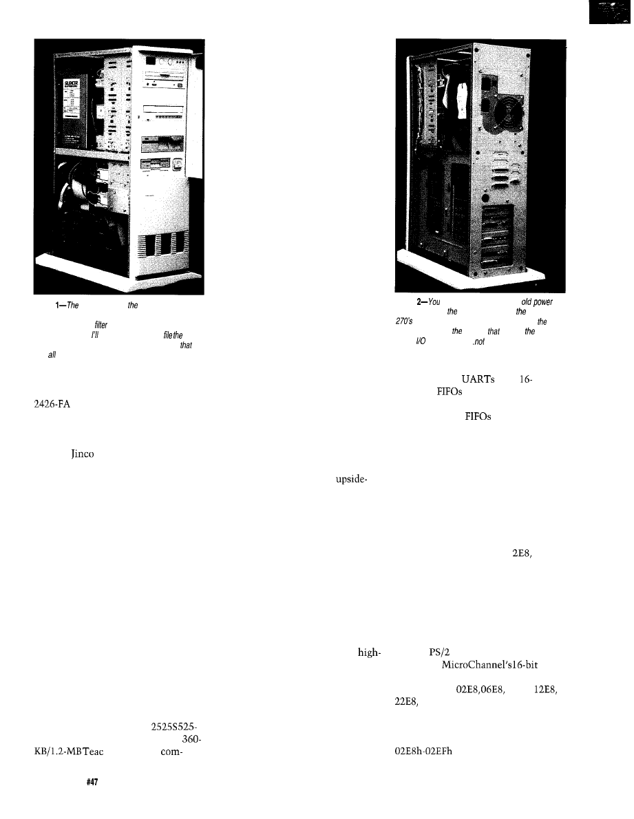
Photo
gaping ho/es in front panel aren’t
aesthetic, but function is more important than form. You
can bare/y see the air
mesh behind
the openings.
One of these days square up the ho/es,
edges, and make if look like if should have been
way along.
side so I installed a pair of Fujitsu
500-MB drives. After two
months of operation, I’m up to about
350 MB, so maybe I was off by a
smidge.
The
780 case has a 3.5”
support bay for two half-high internal
drives and two one-third-high floppy
drives (obviously it’s time for another
height unit!). The two Fujitsu drives
and the floppy looked a little crowded
even though they fit fine. My worst
suspicions were confirmed when I gave
them a thermal trial run: they got
uncomfortably hot.
I didn’t like that, so a bandsaw and
drill press session rearranged the bay
to allow copious free space above and
below the hard drives. I added another
small fan on the case to blow cooling
air between the drives; they now get
just slightly warm. The space made it
easier to arrange the SCSI cables at the
rear of the drives, too.
The rest of the peripherals are
stacked in the external 5.25” bays. A
Toshiba 3401B double-speed CD-ROM
drive is on top, an Archive
MB tape drive is below that, and a
5.25” floppy
pletes the list. There’s an empty bay
between each device to allow lots of
air flow and my calibrated fingertip
reports pleasant operating conditions.
The hard drives, CD-ROM, and
tape drive are all SCSI-2 devices. You
would think the SCSI standard
specifies how to mount the connector,
but either it doesn’t or the folks at
Archive got it wrong: their connector
is upside-down relative to the others.
I
wanted the CD-ROM drive conve-
niently located on top because it’ll see
the most use. That meant I had to
build a custom SCSI cable with a
double half-twist in the middle.
The good news is that my custom
cable has strain relief loops on every
connector so I can pull them out of the
drives without tearing the cable apart.
You don’t get things like that on stock
cables!
The mutually inverted diskette
data connectors are on opposite sides
of their flipped power connectors, too.
I built a custom cable with two “split
and twisted” sections so the 3.5” drive
is A: and in the middle of the cable. I
still haven’t heard a good explanation
why IBM used a custom cable. Maybe
they figured a weird cable was cheaper
than twiddling drive jumpers on the
production line?
I toyed with the idea of flipping
the 5.25” drive, but decided I didn’t
want to insert the diskettes
down.
The Silencer 270 AT power supply
doesn’t leave much room for cables
behind the drives. I arranged things
carefully to avoid blocking the air inlet
despite the SCSI cable’s double half
twist. A few ties on the power cables
keep them out of the way.
SERIAL KILLERS
Most of the embedded systems
projects I work on involve serial
communications for debugging or
during normal use. OS/2 handles
speed serial I/O over multiple ports
quite well, so I got a four-port serial
card using 16550 UART chips that
allows nonstandard port addresses and
interrupts. The card is an MP-011 by
TTC Computer Products sold through
USA Computer Supply, although I’m
sure they have other distributors.
Photo
can see the remains of the
supply cutout on back pane/ around Silencer
fan guard. Note the wood strips befween
system board and chassis
support board
during card insertion..
fancy, but they work!
The 16550
have
character
to buffer incoming and
outgoing data. The IRQ signal goes
active when the
are nearly full
or empty, which means the CPU can
handle up to 16 characters per inter-
rupt. In a multitasking system like OS/
2, that helps ensure you don’t lose
characters during task switches when
the CPU is tied up in noninterruptable
code.
You need independent port
addressing because video cards compat-
ible with the IBM 85 14/A use I/O
addresses that collide with
the
default COM4 address. Serial cards
limited to the standard COM port
addresses will have one useless port in
a system with a high-end video card; in
effect you buy four ports and throw
one away.
The Original 85 14/A was designed
for IBM
systems. It takes advan-
tage of the
I/O
address space, so the actual port
addresses are
0AE8,
and so forth.
The Diamond Stealth manual
sounds this plaintive note: “IBM
originally defined the address space
as reserved, but the IBM
56
Issue
June 1994
The Computer Applications Journal
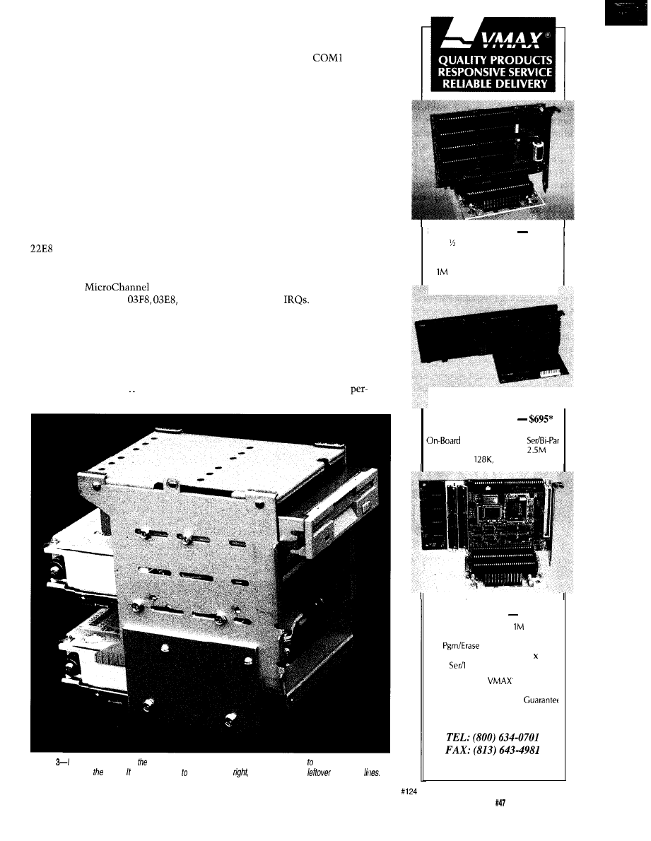
8514/A and successor cards started
using this range as their I/O port.”
Well, folks, if IBM says this
address is reserved and you use it for
something, when IBM later uses it for
one of their cards, you can’t blame
IBM! That’s why they reserved it in
the first place: to keep their options
open for later improvements. Reminds
you of the snafu surrounding Intel’s
“reserved” interrupt vectors, doesn’t
it?
An EISA system board does not
solve this problem, because ISA cards
decode only the 10 low-order address
bits. A video driver writing to I/O port
will clobber the serial port’s
contents. An EISA serial port card
would prevent this, but they’re harder
to find than
cards.
I settled on ports
0260, and 0268. The latter two are
completely nonstandard, but I picked
them by tabulating all the ports in my
system, comparing them with all my
reference books, and finally scanning
them for collisions. Not a pretty sight,
but there you have it..
Serial interrupts in DOS are
normally set up with
on IRQ4,
COM2 on IRQ3, COM3 on IRQ4, and
COM4 on IRQ3 (got that?). Because
DOS is single-tasking, you don’t
usually notice that the interrupts are
shared; with only one port active at a
time there is no conflict. But OS/2 can
drive all four ports at once, so the ISA
bus restriction on shared interrupts is
a problem. Remember that this is an
electrical conflict on the shared lines,
not just a philosophical difference.
The standard OS/2 serial driver
recognizes this problem and expects
each serial port to use a separate IRQ
line. Although Ray Gwinn’s excellent
OS/2 SIO.SYS drivers do support
shared interrupt lines (if the hardware
can handle them), I decided to stay
with dedicated
Unfortunately, when I got every-
thing assembled, there were intermit-
tent serial errors. Sometimes the ports
worked for a while, other times OS/2
didn’t recognize them when it started
up. I swapped in a different multiport
serial port card which worked
Photo
cut the
bottom from infernal drive bay housing and added two side plates allow more space for
ventilation between drives. took a few fries get things just
so there are a few
holes and
SOLID STATE DISK
$135”
Card
2
Disk Emulator
EPROM, FLASH and/or SRAM
Program/Erase FLASH On-Board
Total, Either Drive Bootable
25MHZ 386DX CPU
Compact AT/Bus or Stand Alone
SVGA, IDE, FDC, 2
FLASH/SRAM Drives to
Cache to
DRAM to 48M
TURBO XT
w/FLASH DISK
$266”
To 2 FLASH Drives,
Total
DRAM to 2 M
FLASH On-Board
CMOS Surface Mount, 4.2” 6.7”
2
Par, Watchdog Timer
All Tempustech
products an
PC Bus Compatible. Made in the
U.S.A., 30 Day Money Back
*QTY 1, Qty breaks start at 5 pieces
TEMPUSTECH, INC.
Fax for
fast
response!
295
Airport Roar
Naples, FL 3394;
The Computer Applications Journal
Issue
June 1994
57
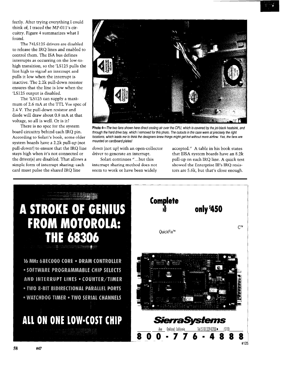
Issue
June 1994
The Computer Applications Journal
And from Sierra Systems:
The
Hardware/Software
So ution for
Sierra Systems is offering a complete PC based development
system that includes a 68306 CPU card, power supply, 68306
Configuration Utility, and a restricted use license to the Sierra
Compiler and
source level debugger.
Whether you are developing software, evaluating the 68000 family,
looking for an engine to drive prototype hardware, or need a pro-
cessor card in an OEM system, this kit is the ideal solution.
6728 Evergreen
l
94611
l
Fox
339.3844
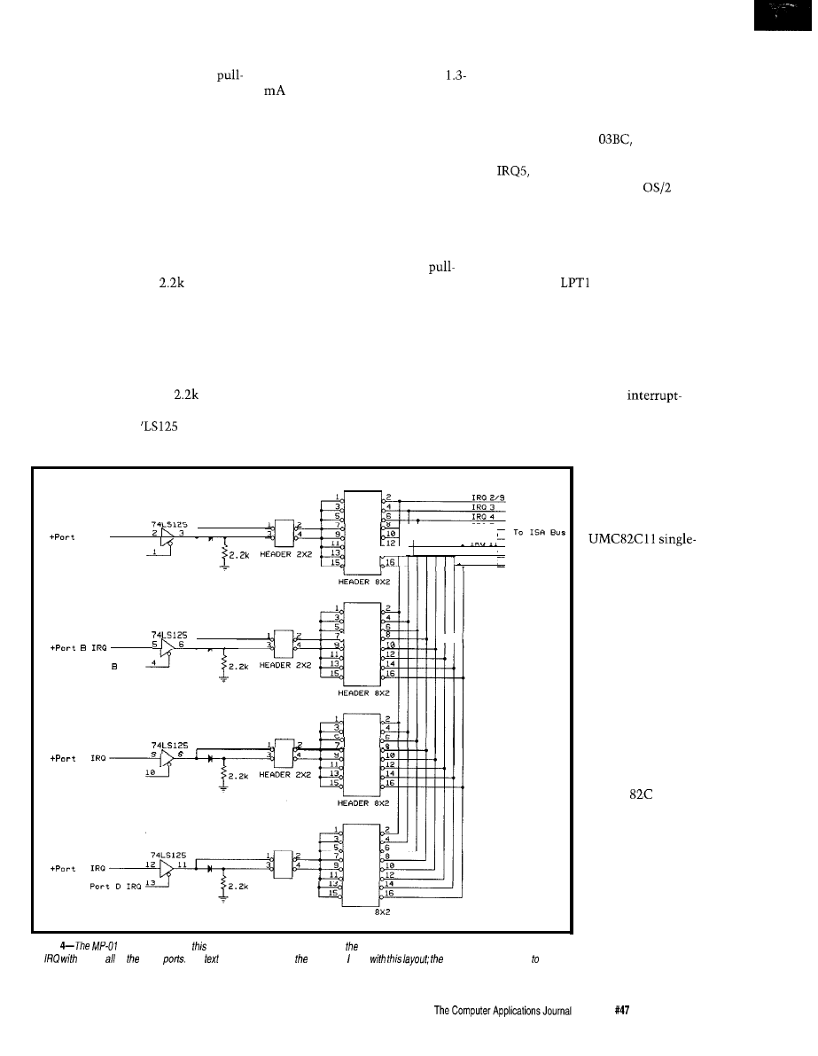
The combination of the system
board pull-ups and the serial card
downs dragged the IRQ lines to about
1.4 volts when the ‘LS 125 drivers were
disabled. That voltage is smack in the
middle of the usual TTL switching
range, neither high nor low. I think
that caused the interrupt controller to
report sporadic interrupts during OS/
2’s initialization. Although the
voltages were fine when the ‘LS125
drivers were enabled, the ports still
malfunctioned for some reason I don’t
understand.
I removed the four
pull-down
resistors and the card works fine. I
think the card would have worked all
right in an ISA bus system without
pull-up resistors, but I can’t test that
option.
The MP-01 l’s interrupt sharing
method places the shared
resis-
tors in parallel. In order to present a
valid interrupt, the
must pull
the IRQ line to at least 2.0 V through a
0.7-V diode drop against a 1.1 k load
(for two shared ports). While the
output current is within the
driver’s specs, the required 2.7-V level
isn’t.. .and it gets worse when you
share more ports. I don’t think the card
could have worked with shared
interrupts.
When
I
need shared serial inter-
rupts to make room for another card,
I’ll replace those generic silicon
junction diodes with Schottky barrier
diodes to reduce the voltage drop. The
shared IRQ will need a single
down resistor to ensure that the line
reaches a valid TTL low voltage when
all of the IRQ inputs are low, but I’ll
do some calculating and measuring to
ensure that it works correctly.
The right solution for an EISA
system combines the IRQ signals on
the card and presents a single driver to
the level-sensitive EISA bus IRQ line.
Since buying this card, I’ve heard that
STB produces a “better” multiport
serial card, but I can’t report on that
one.
PARALLEL POLLUTION
A
- E n a b l e
I
,
.
I I
- E n a b l e
Port
IRQ
c
- E n a b l e
D
- E n a b l e
The system has three parallel
ports at addresses
0378, and
0278 using interrupts IRQ7, IRQ7, and
respectively. Unlike the serial
port situation, the default
parallel port code can timeshare IRQ7
between two parallel ports because
they are output-only: the CPU controls
when an interrupt will occur in
response to a transmitted character.
If only
or LPT2 is active, the
code disables the other port’s IRQ
output. If the other port becomes
active (OS/2 is multitasking, remem-
ber), the code uses the system timer
tick interrupt to control character
output. Works like a champ, although
it’s not as fast as a true
driven port. I have LPT2 connected to
a dot-matrix label printer, so it can’t
get much slower than it already is.
I installed a pair
of KW-508 dual
parallel port cards
from USA Electronics.
These cards use two
chip parallel ports
with a nest of jumpers
selecting the port
address and IRQ lines.
I chose these cards
because they can
support all three LPT
addresses, unlike
many other cards that
allow only 0378 and
0278.
IRQ
I , _
Port A IRQ
, , ,
_
IRQ 12
IRQ15
Port C
I R Q
HEADER 2X2
HEADER
Figure
1 serial card used
interrupt selection circuitry. Each of four pork can have either a unique interrupt or share
an
any or of other
The
describes some of problems had
eventual solution was
remove fhe pull-down resisfors and use separate interrupt lines.
I bought a pair of
cards with two chips
each, figuring that one
of these days I’d need
a spare
11. To
make sure I could find
the chip on that day, I
left it in place on the
card, but removed the
jumpers selecting its
address and IRQ
output. I assumed that
this would disable the
chip by pulling the
chip select input
inactive.
Issue
June 1994
5 9
Hell hath no fury like that of an
unjustified assumption.
Like most CMOS logic, the
select input driven by the address
decoding logic does not have an
internal pull-up resistor. As a result,
the system would crash every now and
again when that pin drifted low
enough to activate the chip. When the
sees an active chip select input,
it responds to the
bus signal by
driving its data onto the bus, much to
the detriment of whatever was
actually using the bus at the time.
I now have an
chip nested
in antistatic foam where it’ll stay until
just before I need it, whereupon it will
lose itself. And, yes, I learned that bit
about CMOS chips long ago. Some-
times you do things that, seen in
hindsight, are really stupid. Right?
THE VIDEO VIEW
My Model 80 has been running
with 1024x768 dots in 256 colors ever
since I started using
Although
that’s a perfectly serviceable resolu-
tion, a GUI blots up screen real estate
quite quickly. A typical session might
have the C compiler in a DOS win-
dow,
in a large OS/2 text
window, Borland C’s Windows help
system, a pair of REXXTERM windows
for serial communications, and two
Describe windows for the manual and
article..
get
the picture.
I picked a Diamond Stealth Pro
VLB card for my new system because
it supports display resolutions up to
1280x1024 with a 70-Hz noninterlaced
vertical refresh rate. It uses an S3 928
graphic accelerator chip to boost bit-
mapped graphic performance. IBM has
a 32-bit OS/2 video driver supporting a
variety of
cards including the
Stealth.
It turns out, though, that the 928
chip has a little bug requiring a
firmware workaround to produce
1280x1024 dots at 70 Hz
laced. That workaround was inadvert-
ently left out of the final IBM beta
driver. The “real” version is scheduled
for the OS/2 2.1 Service Pack, so, until
it shows up, my display runs at 43.5
Hz interlaced. There’s lots of dots, but
it is just slightly
when seen
from the corner of the eye. Ah, well.
You must consider the monitor
size when you pick a display resolu-
tion. Obviously the monitor must be
capable of handling the horizontal and
vertical scan rates and have a video
bandwidth large enough to display
crisp lines that may be only one dot
wide. Skimping on these specifications
produces a blurry image that will do
your eyes no good at all.
The monitor must also be large
enough to adequately display the dots.
The limiting factor is the shadow
mask that produces the color triad
needed for each image dot. Typical
shadow masks have a dot pitch around
0.28 mm, which means a 1280x1024
image will be about
In a
rational world, you’d buy a monitor
with an 18” diagonal screen.
But this isn’t a rational world.
Most manufacturers produce monitors
in discrete sizes: 14, 15, 17, and 21
inches. The diagonal measurement is
from corner to corner of the glass tube;
the bezel covers an inch or two of
that distance. In order to get a real 18
inch diagonal you need a 2 1 inch
monitor!
Buy a copy of Computer Shopper
before
excellent power supplies and
you
do anything else. Sources, prices,
ments. Make sure you know the physical
and availability have certainly changed
and electrical size of the supply you need
since I bought my system in late
before you call. I deliberately got a larger
My system fulfills my specific needs;
supply knowing I’d need some sheet-metal
yours are certainly different and demand
work, but you probably want a drop-in
the same careful evaluation used.
replacement.
Case:
Computers. (818) 309-1108,
fax: (818) 309-1107. A wide variety of
cases with a helpful tabular listing of
features. They also carry complete
systems, power supplies, and suchlike.
2742T SCSI-2 controller, Toshiba
3401B SCSI-2 CD-ROM drive:
Ability. (800) 554-9950, fax: (414) 357-7814.
A broad-spectrum PC software and
hardware supplier.
Enterprise III
system board:
Washburn Company. Motherboard
hotline: (800) 836-8027, fax:
7549. They also carry AM1 peripherals,
and many other items. They
have good RAM prices, so buy it
directly from them to avoid
pointing should there should be any
problems. My RAM worked fine, but
there are a lot of transistors in 32 MB!
Fujitsu
520 MB SCSI-2 hard disk:
U.S. Computer Supply. (800) 987-7877, fax:
(516)
Lots of hard drives, system
boards, and other PC paraphernalia.
Multiport serial and parallel cards, floppy
drives: USA Electronics, Inc.
631-
1693, fax: (214) 631-4817. A wide array of
PC gadgets and parts.
Silencer 270 power supply: PC Power
Cooling, Inc. (800) 722-6555, fax: (619)
93 l-6988. They have a wide variety of
Adapters, connectors, etc: Computer Gate
International. (408)
fax: (408)
0735. These folks specialize in generic
cabling and connectors.
The video cables
and switchers are not up to the needs of
high-performance monitors, but that’s
true of nearly all nonspecialist vendors.
SCSI connectors, ribbon cable, all
manner of good electronics stuff:
Key Corp. (800) 344-4539, fax: (218)
3380.
Hitachi
Elite 21, Diamond
Stealth Pro VLB, Microsoft
mouse:
USA Flex. (800) 723-2261, fax: (708)
7204. Another broad-spectrum PC
hardware and software source.
Miniature full-size keyboard: Datalux.
(703) 662-1500, fax: (703)
The
cutest little keyboard you’ll ever meet,
available with PC and
connectors.
Much better than the full-size monsters
that eat your entire desktop.
Shared-IRQ OS/2 serial port drivers: The
Software Division, Raymond L. Gwinn,
12469 Cavalier Dr., Woodbridge, VA
22192. Good high-performance shareware
with excellent support through
CompuServe.
60
The Computer Applications Journal

The Hitachi
Elite 21
has a bezel opening of about
yielding a
diagonal despite the
brand name. It has digitally controlled
everything, a tilt/swivel base, and
comes with a surprisingly long coaxial
cable harness. It can handle up to
horizontal and 150 Hz vertical
refresh rates with a video bandwidth of
135 MHz.
When I unpacked the thing (from a
box roughly the size and weight of a
Hyundai with Rhode Island crumpled
inside for packing material), a problem
appeared that should have been
obvious much earlier: how do two
ordinary people get an
monitor onto a desk? Mary and I gave
it the old heave-ho, but, verily, I hope
the next generation of monitors uses
LCD technology!
supports a wide variety of
video resolutions, but there is no way
for it to know your actual monitor
size. VGA-resolution programs such as
are overwhelming. Describe,
the
word processor I use, as-
sumes that it’s crammed into a tiny
bezel and enlarges its
icons so
they’re half an inch square. Ah, well,
maybe next release..
Incidentally, at this level of video
performance, you cannot use ordinary
video cables or switch boxes because
they are not impedance-matched to
the monitor’s
inputs. One of
these days I have to build a
performance switcher to reduce the
number of monitors and keyboards on
my desktop.
UP AND RUNNING!
Although it may sound like
everything went wrong with this
system (and I haven’t told you every-
thing!), most of the problems suc-
cumbed to patient testing and careful
notebook work. I can’t overemphasize
the importance of good notes: when-
ever I failed to write something down,
it came back to haunt me later.
OS/2 is an operating system that
brings many hardware conflicts and
problems to the foreground. As DOS
fades into history, you’ll see more and
more of this trouble: things that used
to
work fine suddenly start acting up
because the new software takes
advantage of all the hardware features.
OS/2 just happens to be the first really
heavy-duty operating system to gain
significant market share.. .any
multitasking, protected mode, virtual
memory OS will run headlong into the
same issues.
In the next series of articles, I’ll
return to the ‘386SX project and the
Firmware Development Board with
something you’ve never seen
before..
synched!
q
Ed Nisley, as Nisley Micro Engineer-
ing, makes small computers do
amazing things. He’s also a member of
the Computer Applications
engineering staff. You may reach him
at
or
corn.
413
Very Useful
414 Moderately Useful
415 Not Useful
LCD PANEL METER
-Available now at an unheard of
N e w ! N o t s u r p l u s !
Specifications:
Maximum input: f199.9
additional ranges provided through
external resistor dividers
Display: 3%digit LCD, 0.5 in. figure height,
jumper-selectable decimal point
Conversion: Dual slope conversion, 2-3
readings per sec.
Input Impedance:
ohm
Power: 9-12 VDC 1
DC
Circuit Cellar, Inc.
4 Park Street, Suite 12, Vernon, CT 06066
Tel: (203) 875-2751
Fax: (203) 872-2204
Memory mapped variables
n
in-line assembly language
option
Compile time switch to select
805
1 or
Compatible with any RAM
or ROM memory mapping
n
Runs up to
50 times faster than
the MCS BASIC-52 interpreter.
includes Binary Technology’s
cross-assembler
hex file
n
Extensive documentation
Tutorial included
Runs on IBM-PC/XT or
n
Compatible with all 8051 variants
$295.
508-369-9556
FAX 508-369-9549
Binary Technology, Inc.
P.O. Box 541
l
Carlisle, MA 01741
The Computer Applications Journal
Issue
June 1994
6 1
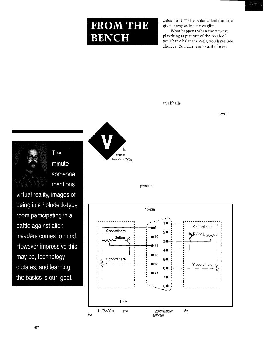
Jeff Bachiochi
about it until you can afford it, which
may translate into permanently
forgetting about it because it’s too far
Virtual Reality Requires
Real Data
from reality. Or, you can make it
happen by being a bit ingenious.
COMMON INPUT DEVICES
Input devices for personal comput-
ers have stratified into two groups: the
moving-ball type, including mice and
Part l-Collecting Data with an
Exoskeleton
and the stick type, which
includes joysticks and keypads. Both
work well for moving around a
dimensional screen, however both fall
short when thinking in 3-D.
In the world of tridementia,
pointing devices must take on addi-
tional complexity to work in height,
irtual Reality
width, and depth. You may have seen
has become one of
the 3-D digitizing device which looks
the newest techno-fads
like a small arm. Coordinates for a
for the
Like most
point are calculated using measured
other new ideas that push the envelope
angles and arm lengths. Although it is
of technology, an entry-level VR
a bit clumsy, this method does have
system carries a high price tag. And
the benefit of being inexpensive.
like other leading-edge gimmickry, the
Although I don’t have a degree in
costs stay high as long as the
medicine, I’ve always had a fascination
tion scale remains small. How much
with the mechanics of the human
did you pay for your first A-function
body. This project will attempt to
Joystick B
Male D-shell
Connector
Joystick A
015
Note: Potentiometer for X and Y coordinates has a range of 0 to
ohms. Button is normally open; closed when pressed.
Figure
game
works by accepting a
input As resistance varies, an oscillator in
PC changes ifs rate, which can be measured by
62
Issue
June 1994
The Computer Applications Journal
i
0.7"
Figure
of
exoskeleton
begins with design of the simulated joints. This involves
soldering together potentiometers and small pieces of
brass stock.
mimic actual arm movements by
constructing an apparatus to measure
real-time movements and transmit the
collected data to a PC. The PC will
translate the data back into movement
for display.
RADIO SHACK
SHOPPING LIST
Almost everyone has a Radio
Shack somewhere close by. I like to
stop in from time to time just to see if
they have anything new. On this visit,
however, I knew what I was after: a
handful1 of linear-taper potentiometers
(anything around
would be fine).
And I was also seeking a few bags of
control knobs. You know the
the ones with those brass inserts.
NEXT STOP, HOBBY WORLD....
Many modeling hobbyists are
familiar with telescoping brass tubing.
This structural material comes in a
full selection of stepped sizes which
slide into one another like a car’s
antenna. I rummaged though the
selection and picked out a few assorted
sizes of both square and round tubing.
The round tubing can be used when a
change in length is necessary without
the need to transfer rotational position
along the length of the extended tube.
But when rotational transmission is
required in addition to a change in
length, square tubing is used.
BOUNCING IDEAS OFF THE WALL
TRYING TO FIND THE ONE THAT
WOULD STICK
toyed with the idea of using the
joystick ports on a PC. Since there are
four analog (resistive) inputs on a PC’s
game port, you can use these quite
successfully for some limited applica-
tions. For those of you who wish to
experiment with this, see Figure
1
for
the schematic used for connecting four
potentiometers to this port. The
port uses capacitors internally that
have a fixed value, which, when used
in conjunction with an external
adjustable pot, can create a variable
time constant. The time constant
produces a measurable time delay
where the delay represents position.
When a potentiometer has a lever
attached at right angles to the shaft
(like the hands of a clock), it simulates
a joint which has movement on one
axis. My first step in producing a joint
of this nature involves a nutcracker. If
you have misplaced yours, any ham-
mer will do nicely. Grab the control
knobs you’ve purchased and whack off
all the plastic, leaving only the brass
inserts. These brass inserts can easily
be attached to, removed from, or
adjusted on a potentiometer’s shaft.
For a multiple-axis joint, potenti-
ometers must be assembled to one
another using levers which are as short
as possible. I tried small pieces of
fiberglass epoxy [cut from
for
the joint levers with a brass insert
epoxied to the end, but the bond
cracked when I accidentally dropped
an assembled component. So I sensed a
need for a redesign. For the second
attempt, I used a small piece of flat
brass stock (following a quick trip back
to the hobby shop). The bond between
the brass pieces is made by soldering
them together using a standard
soldering iron. For the plumbers out
there, you could use a propane torch.
Whatever your heat source, be sure to
work on a noncombustible surface. See
Figure 2 for the part dimensions and
Figure 3 for the construction plans for
a three-axis joint.
This three-axis joint simulates the
movements of a shoulder socket joint.
The joint is held in place on top of the
shoulder by a platform made from
scrap aluminum and held firmly in
place with one-inch-wide elastic
straps, similar to the shoulder holster
worn by private investigators.
The upper arm is the shoulder’s
lever and, likewise, a lever made from
brass tubing is attached to the
shoulder’s third-axis potentiometer.
The arm lever must be attached to the
lower part of the upper arm just above
the elbow. Since the elbow is a single-
B a s e
A r m
X-Axis
Figure
most coarse
of information is obtained from shoulder assembly, which can computer
whether
arm is over person’s head or at his side.
The Computer Applications Journal
Issue
June 1994
6 3
From Shoulder
Arm Mount
Wrist
Rotation
Figure
next
of
is obtained from
which a/so includes a measurement of wrist
rotation.
axis joint and can be mimicked by a
shoulder lever tie down. (Actually, this
location will serve a third function by
holding a second potentiometer to
single potentiometer, the attachment
measure the wrist’s rotation, see
just above the elbow can serve two
Figure 4.)
purposes: the elbow joint and the
The potentiometers used for the
elbow joint and wrist rotation are
attached to the center of a “C” shaped
aluminum strap that is held on the
user’s arm by an elastic strap. Small
strips of Velcro make it easy to attach
and remove this band. The shaft of the
potentiometer on the elbow is long
enough to capture both the end of the
upper arm lever (the set
screw is left loose) and
the four fingers and thumb have
many individual joint movement
the lever for elbow movement and
combinations. These can be simplified
wrist rotation.
by compromising on capturing only
one type of motion: the opening and
closing of the fingers. Using this
Using this method for the finger’s
compromise requires that one last pot
be mounted on the back of the hand
joints could get extremely
near the knuckles to measure the
position of the middle finger. This
arrangement assumes the thumb does
not move, while it actually works in
concert with the fingers to grasp
objects. See Figure 5.
RESOLUTION
Potentially, (sorry) a joint might
have
of motion, though in reality,
most joints are limited to about
The mechanical limit of a linear-taper,
carbon-type potentiometer is about
300”. Normal movements will not
exceed the mechanical limits of the
pots (unless you happen to have a
strong windup and mean fast ball). By
placing a known voltage across the
potentiometers, we can detect the
position of the lever connected to the
pots’ shafts by measuring the voltage
at the wipers. This change in voltage
is directly proportional to a change in
degrees of rotation.
Because each mechanical joint’s
pivot point differs from the actual
joint’s pivot point, the mechanical
joint may move more or less than the
actual joint. By calibrating each joint,
we can artificially correct for these
differences and determine the relation-
ship between movement and measured
voltage. To do this, the voltage change
is recorded from each potentiometer as
the actual joint is moved through a
known rotation. The difference in the
voltages measured before and after the
movement is divided by the number of
degrees of movement giving the
voltage change per degree. See Table
the potentiometer that is
used to measure the
wrist rotation in the
lower part of the arm.
A wrist band is
similarly constructed
using two potentiom-
eters to measure the
remaining two axes of
motion of the wrist. The
wrist rotation is coupled
through the telescoping
square tubing from the
wrist band to the elbow
joint’s band. This is not
the normal levered joint
action, but a rotational
difference between the
wrist and elbow, thus
the need for square
telescoping tubing. This
Figure
final piece
frame is the addition of a potenfiomefers for
wrist motion and fhe movement of
length of tubing provides
closed or open fingers. Although
may seem simplistic,
pot measures fhe position of middle finger, which, in this
case, sufficiently represents fhe
of rest of digits.
64
Issue
June 1994
The Computer Applications Journal
Table l--The
consists
of
joints, each of which
be calibrated
accurate movements and measurements.
for the calibration of each of the eight
joints measured.
TALKING THE SAME LANGUAGE
The standard PC does not have the
ability to accept analog voltages. In
order to pass it this kind of data, it
must be converted first into binary
representations of the analog voltages.
I grabbed the RTC52 and RTCIO
boards for this simple conversion.
With these two boards, I have an
channel,
A/D converter plus a
processor that I can easily program in
BASIC. The simple program (see
Listing 1) waits for any character to be
received through the serial port. Then
eight bytes of data representing the
last sample of the potentiometers’
positions (one value for each channel)
are sent out the serial port at 9600 bps.
The A/D converter accepts a
volt input, so use 5 volts across all the
potentiometers. The wipers will vary
l
T
medi
medi
Joint
Fingers
Wrist
Shoulder Shoulder Shoulder
Axis
Y
Y
X
Z
Y
X
Y
Z
A Voltage
0.5
0.5
1.25
1.25
0.4
0.7
0.6
1.15
A Degrees
45
90
90
180
90
90
90
90
Volts/Degree
14mV
7 m V
Degrees/Bit
1.8
3.6
1.5
2.8
4.5
2.6
3
1.5
Listing 1-A
program constantly updates last position measured
movements of
exoskeleton.
10
:
:
:
:
20
:
:
:
30
1000
40
50
1000
100
G=GET
110
IF
THEN GOT0 110
120
FOR
TO 7
130
140
150
NEXT X
160
GOT0 110
1000
FOR Y=O TO 7
1010
1020
1030
NEXT Y
1035
IF
THEN
1040
RET1
REM Zeroing constant
RETURN
CELLAR KITS
Sonar Ranging Experimenter’s Kit
EEG Biofeedback Brainwave Analyzer
Targeting Ranging Machine Vision
The HAL-4 kit is a complete
The Circuit Cellar
Ultrasonic Sonar Ranger is based on the
electroencephalograph (EEG) which
sonar ranging circuitry from the Polaroid SX-70 camera system. The
and the original SX-70 have similar performance but the
Sonar
measures a mere
HAL is sensitive enough
Ranger requires far less support circuitry and interface hardware.
to even distinguish different conscious
The
ranging kit consists of a Polaroid
between concentrated mental activity and
ant daydreaming. HAL gathers all relevent alpha,
static transducer and ultrasonic ranging electronics board made by Texas
Instruments. Sonar Ranger measures ranges of 1.2 inches to 35 feet, has a
beta, and theta brainwave
TTL output when operated on
and easily connects to a parallel
signals within the range of
printer port.
Hz and presents it in a
serial digitized format that
can be easily recorded or
Sonar Ranger kit. . . . . . . . . . $79.00
plus shipping
analyzed.
CHECK OUT THE NEW CIRCUIT CELLAR
HAL’s operation is
straightforward. It
four channels of analog brainwave data 64
HOME CONTROL SYSTEM
times per second and transmits this digitized data serially to a PC at 4800
bps. There, using a Fast Fourier Transform to determine frequency,
amplitude, and phase components, the results are graphically displayed
in real time for each side of the brain.
Expandable Network
Digital
and
Analog I/O
Interface
Voice
Interface
Remote Displays
Interface
HAL-4 kit.
plus shipping
he
Cellar
Level detector is presented as an engineering example the
techniques used in
signals. This Hemispheric Activation Level detector is not a
approved device, no medical claims are made for
device, and should not be used for
purposes. Furthermore, safe use
that HAL be battery operated only!
To order the products shown or to receive a catalog,
call: (203) 875-2751 or fax: (203) 872-2204
Circuit Cellar Kits
l
4 Park Street
l
Suite 12
l
Vernon, CT 06066
66
Issue
June 1994
The
Applications
Journal
from 0 to 5 volts with a
then saved as a base of reference. The
maximum rotation. The S-bit ADC
future samples are subtracted from
has a resolution of about millivolts
this base to produce data which is an
per bit with a
reference. The
offset from the zeroed base. The eighth
resolution divided by the volts
bit (the sign bit) denotes direction: 1
per degree gives a relationship of about
for counterclockwise and 0 for clock-
one degree per bit between the actual
wise joint movement. Using factors
movements and the data values read
determined in the previous calibration
from the ADC. See Figure 6.
step, the converted data for each of the
The short BASIC program
joint measurements is transformed
rates a “zeroing mode.” This mode is
into degree data. This relative degree
entered by grounding the external
data, referenced from the zeroed base,
interrupt pin on the processor. The
is what is actually transmitted
next sample of every joint’s position is
whenever data is requested.
Zeroing
S e r i a l P o r t
9 6 0 0 b a u d
.
.
.
.
Figure
method for
converting
analog voltages to
their binary
was
by
using an
RTC52 and
an
with its
8-bit
converter.
This could have all been done
with a small micro having an internal
ADC and external channel multi-
plexer, but that isn’t the purpose of
this project. You may wish to experi-
ment with other interfaces or using
the PC’s game port. The direction you
take might depend on the number of
joints you wish to monitor.
Assuming you are wired by next
month, I’ll look into the logistics of
dealing with this data in a virtual
world.
Bachiochi (pronounced
AH-key”) is an electrical engineer on
the Computer Applications
engineering staff. His background
includes product design and manufac-
turing. He may be reached at
416 Very Useful
417 Moderately Useful
418 Not Useful
TWO PROGRAMS FOR ONE LOW PRICE!!
SUPERSKETCH PCB II:
INTEGRATED
PCB II & SUPERSKETCH features:
l
MOUSE DRIVEN *SUPPORTS CGA, EGA, VGA SVGA,
l
OUTPUT TO 9 24 PIN PRINTERS, HP LASERJET&
HPGL
l
OUTPUT TO DTP PACKAGES *
l
PCB II ALSO HAS GERBER OUTPUT VIEWING.
l
THF EASIEST TO
CAD
R4 SYSTEMS Inc.
1111 Davis Drive, Suite
Newmarket, Ontario
fax (905)
ALL PRICES ARE IN US FUNDS. PLEASE INCLUDE $7
NEW! UNIVERSAL DALLAS
DEVELOPMENT SYSTEM
It’s a complete single board computer!
One board accommodates any 40 DIP
SIMM
SIMM DS2252, or 72 SIMM
processor! Snap one out, snap another in.
Programs via PC serial port. Program lock encrypt.
LCD interface, keypad decoder, RS232 serial port,
ADC, four 300
relay driver outputs.
Power with 5VDC regulated or 6-13 VDC unregulated
Large prototyping area, processor pins routed to headers
Optional enclosures, keypads,
everything you need
BCl51 Pro BASIC Compiler
Dallas keywords
The Computer Applications Journal
Issue June
1994
67
Fear
Loathing
in
L.A.
Tom
WAY 101 SOUTH
Watched
“The Doors”
on TV last night. “The world is
screaming for change, Morrison.”
Changes are coming all right, but
have a feeling the screaming has just
begun..
LA-riots, fires, floods, and now
earthquakes-truly a city of biblical
proportions. Sure, no locusts yet-but
watch out for those killer bees!
Hurtling south, the turbo whistles
along with my thoughts. yeah, LA
chewed
up and spit him out, just
another lost angel in the city of lights.
Waiting for the sun to rise; The
horizon, like the turbo, glows red. Is it
just the dawn, or is LA burning!
The last time I visited the Digital
Hollywood show, I wrote about the
technical challenges and uncertainties
lining the yellow brick road to the
mythic PC-Video
Virtually-Real future (“Multimedia
Madness,” issue
Since then, a lot of progress has
been made on the technical front. For
instance, what was a potentially nasty
spat between HDTV schemes has been
more or less laid to rest by the “Grand
Alliance.” After years of bickering, the
HDTV
is nearly final.
Technology marches on and the
silicon wizards have more goodies
than ever to pull out of their hats.
Sure, an MPEG2 (the preferred com-
pression scheme of the “Grand
Alliance”) chip requires a million
transistors or so, but it will only get
easier as the fabs head toward 0.1
With the horsepower to handle
full-motion A/V, PCs are becoming
ever more “multimedia capable” and
the installed base of CD-ROMs is
growing at a healthy clip. The Mac,
thanks to Quicktime, is leading the
way, but the Windows camp is
gathering steam and will eventually, as
usual, muddle through.
Meanwhile, video games-thanks
to a marketing-inspired “bits
are quickly graduating from the toy
store. Indeed, not shackled by the
burdens of PC compatibility, the next
generation of “64-bit” RISC games
from the likes of
Nintendo/SGI,
and Sony will arguably challenge the
PC for computing supremacy.
Now the emphasis is shifting from
what “can be done” to what “should
be done.” The answer is nobody really
knows-but they all think they do-
ensuring we’ll see some rather spec-
tacular “crash bums” in the race to
the TV of tomorrow.
WELCOME TO HOLLYWEIRD
It’s fitting that my first encounter
at the Digital Hollywood show was
with The Great Kat. I say “encounter”
rather than “interview” because the
latter implies an aura of normalcy that
was definitely missing. Yeah,
you’re not in Kansas anymore..
[Editor’s note:
Tom begged us to run a
photo of The Great Kat, but it was just
too crude for our family-oriented
magazine.]
You
say you haven’t heard of The
Great Kat, self-proclaimed “Vicious
Tasmanian devil speed demon guitar
wizard Juilliard graduate violin
virtuoso genius composer?” As you
might imagine, Kat-toons like “Re-
venge Mongrel” from the “Beethoven
On Speed” album likely appeal to a
rather exclusive audience..
. .
“AH! You
went too far this time
PEON! You picked the WRONG
person
WITH! Y
OU
will suffer for your actions”
.Oh, suffer I did. You see, The
Great Kat doesn’t talk-she SHOUTS
every word, running sentences to-
gether at hyperspeed, with a typical
“Kat Kuote” going something like:
“GET INTO THE 21 ST CEN-
TURY YOU DRUGGED OUT MO-
RON THE GREAT KAT IS THE
FASTEST MOST POWERFUL
68
Issue June
1994
The Computer Applications Journal
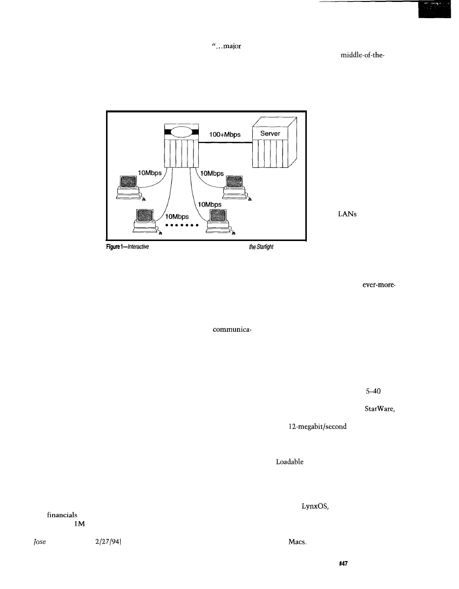
GER BLEEDING SKULL CRUSHING
MIND WARPING BLOOD DRIPPING
TEAR YOUR LUNGS OUT RIP
YOUR EYES OUT SMASH YOUR
BRAINS IN POWER PACKED MUSIC
EVER HEARD I’VE GOT TO LIVE
WITH THIS MASSIVE BRAIN 24
HOURS A DAY SHUT UP MORON”
“Loyalty Program Manager” who is
supposed to launch a
new
loyalty program to retain subscribers
of IN’s interactive programming
service.”
Hey Kat, if the “digital hyper-
media” business doesn’t pan out,
I
suggest you give the folks at IN a call.
I made sure not to
show overt fear since any
sign of weakness might
be, as in a stare-down
with a mean dog, a
dangerous proposition.
You don’t want to mess
with someone who sings
little ditties like, “I
SHOVE MY HEEL INTO
YOUR HEAD.”
Hub
Along with my
career choice, some
might question the Kat’s
claim to a “(
EXPLETIVE
)
180 IQ.” However, I did
come away (body intact,
mind less so) from the
of consumer electronic user interfaces,
save your sanity as well.
My guess is that
road (er, -superhighway) stuff like
VOD is obviously sellable-the only
question is when, which of course
depends on cost. If I can order a movie
for a few bucks, I’m sold.
However, I suspect
the price tag is likely to
be higher than hoped by
the hypsters. Whichever
way you cut it, delivering
50 million different
programs to 50 million
TVs at once isn’t going to
be easy-or cheap. Toddle
on over to your local
Computer Shoppe and ask
about 100 terabyte/
second
and you’ll
see what I mean. These
days there isn’t enough
money around to fix the
regular highway, much
television of the near
future may consist of
LAN-based
Video On Demand setup.
less build a new info
superhighway. Just who’s going to pay
for all this stuff, anyway?
encounter with a few key insights.
For instance, one argument
justifying the “need” for 500 channels
is that the Hollywood studio/agent/
lawyer combine conspires to suppress
“fringe” or “nonmainstream” artists
who will only be liberated by a
bandwidth explosion. However, the
fact these same power brokers have
seen fit to welcome The Great Kat into
the inner sanctum works against that
proposition. As far as I can tell, the
only thing that matters to the moguls
is whether they’ll make enough bucks
to buy a new Beemer.
But it was her last command, “I’M
GOING TO FORCE YOU TO INTER-
ACT!” that really got my attention.
Judging by early results from the
Interactive Network Inc., a little
FORCE may be required to move
things along. Their service+handheld
gizmo purports to offer “...a revolu-
tionary entertainment service where
you play along with your favorite TV
shows including sports, game shows,
news, mysteries, and educational
programming.” Unfortunately, for FY
‘93, their
show a $24.7
million loss on $1.
revenue.
They’re also running a hiring ad
(San
Mercury News,
for a
INTERACTIVE POTATOES
To interact or not, that is the
zillion dollar question. Unfortunately,
the definition of just what “interac-
tive” means isn’t clear, and the term is
bandied about with great recklessness.
After all, in the simplest sense of
the word-“two-way
tion”---everyone has “interactive TVs”
already. Every time you push the
channel, pause, or mute buttons on
your IR remote, you’re “interacting.”
At the other extreme, proponents
speak of a future in which you can
play along with the game show, direct
the story line of a soap opera, choose
the camera angle at a sports event, or
sing along with the band.
Somewhere in the middle is the
“interactivization” of existing ser-
vices. The most popular candidate is
“Video On Demand” (VOD) which
electronically replaces today’s ritual of
driving to and from the video rental
shop. Home shopping saves trees
consumed by mail order catalogs and
you don’t have to leave your fortress
and actually go to some place where
you might get mugged. On-screen
program guides that link with your
VCR to schedule recording save more
trees and, given the ever dismal state
Nevertheless, fueled by
for-less technology and a healthy dose
of raw greed, some kind of “info
highway” will get cobbled together,
even if it requires a wiring closet in
every garage and Cray in every TV. In
the meantime, there are practical
applications for VOD-training
centers, kiosks, and the like-that are
feasible with today’s technology.
Starlight Networks offers software
that turns a standard PC-based LAN
into a VOD setup supporting
users-an “info pathway” if you will.
The entry-level product,
comes in 6-megabit/second ($4,495)
and
($8,750)
versions and works by simply sitting
on top of the ever-popular Novell
Netware as an NLM (Netware
Module). The Netware
underpinnings dictate a PC-only
environment at this time.
Starworks achieves higher perfor-
mance-up to 50 megabits/second-by
running
a real-time-oriented,
UNIX-like OS, on the server. Further-
more, while the server must be a PC,
clients can be a mix or match of PCs
and
The Computer Applications Journal
Issue
June
1994
69

Pricing and part numbering by
bandwidth as opposed to number of
users makes sense for a couple of
reasons. First, the MPEGl data rate of
150K bytes/second (i.e., 1.2 megabits/
second) is assumed when translating
bandwidth to users (e.g., 6
Mbps = 5 users). In fact, each user is
allowed to run video using one of the
many alternative compression
schemes supported. For example, a
megabit/second
setup
($24,995) could support 40 MPEGl
users, 12 Motion-JPEG users, or any
combination (e.g., 6 Motion-JPEG and
20 MPEGl that adds up to 50 mega-
bits/second.
The other reason to make the
bandwidth requirements explicit is it
reminds you to make sure your
hardware specs-notably CPU speed,
RAM space, disk throughput, and LAN
bandwidth-are up to snuff. Sure, the
entry-level setup can run on a plain old
‘386 + Ethernet setup. On the other
hand, a
installation
needs a speedy CPU
or better),
multiple disks (SCSI II RAID), and lots
of RAM (24 MB).
The worst bottleneck is the LAN,
with all but the smallest setups calling
for an active hub (i.e., dedicated port
for each video stream) and a high
bandwidth (e.g., FDDI at 100 megabits/
second) connection between the hub
and a dedicated video server (Figure 1).
Get your checkbook ready because
while 1.2 megabits/second may not
sound so bad, remember that another
way of saying it is 540 MB/hour! The
next time you’re talking with a disk or
RAM supplier, see how easy it is to
invoke a Pavlovian drool whenever
you start talking about multimedia.
WHO’S IN CHARGE
The traditional rivalry between
San Francisco and Los Angeles pro-
vides a fitting backdrop for the battle
between Silicon Valley and Hollywood
for multimedia supremacy.
It’s much more than whose sports
teams are better, restaurants tastier, or
politicians more correct. Rather, it’s
the completely different way of doing
business in each industry that has big
implications for the outcome of the
digital revolution.
Hollywood is a mature business,
the first “moving picture” having been
created nearly 100 years ago. Everyone
knows their role in life and the game is
played according to well-understood
By comparison, Silicon Valley is a
gawky teenager that, thanks to raging
hormones, does great and foolish
rules-everything from “don’t call us,
things. Sometimes at the same time.
Admittedly, the people and business
we’ll call you” to the casting
are aging, but there’s still a “hope I die
before I get old” mentality.
that haven’t changed for decades.
Perhaps it is the cost dynamics
that most starkly define the difference.
Hollywood, being somewhat labor
q
“After awhile, the
news is read television
children fed..
Unknown
The Doors
intensive and held hostage to the
celebrity mentality, is not known for
cutting costs. Generally, the prices for
everything (movie production, ticket
prices, video tapes, CDs, etc.) tend to
rise or at least remain relatively flat.
On the other hand, Silicon Valley
and the microelectronics industry is
unique in continually offering more for
less. The physics-induced cost cuts in
hardware drag along even the
intensive software business with last
year’s $500 “business package” being
sold as this year’s $99 bundle.
This brings up the point that
while both movies and spreadsheets
are loosely referred to as software,
there is a big difference. Good movies,
like fine wine, tend to age well, and
many of the silver screen classics are
arguably better than the latest and
greatest action flick. By contrast, old
computer software ends up on the junk
heap, which helps to explain the “sell
it today at any price before it’s worth-
less” strategy.
Consider the recent brouhaha in
which the music companies have
threatened to withhold new releases
from retailers that dare to offer “used
CDs.” It isn’t just the “suits”
the campaign has been backed by a
number of “recording stars” who
actually keep a straight face when they
Meanwhile, computer software
whine that I shouldn’t be allowed to
suppliers have killed the once nascent
“rental” business which Hollywood
buy or sell an old CD. Of course, this
embraces. The original reason was that
many “renters” were really “rip offs,”
but that’s not all there is to it. For
is only an issue because the old CD
instance, Blockbuster has recently
begun renting CD-ROM games and the
retains value indefinitely.
producers aren’t too happy about it,
though the concern isn’t piracy.
Instead, they fear that instead of
selling X copies, they’ll only sell X/Y
copies, each being rented to Y people.
Remember, an old game, unlike an old
song, is pretty useless.
One obvious difference between
Hollywood and Silicon Valley is the
degree of unionization. The traditional
“media” businesses (film, music, TV,
newspapers, etc.) are all unionized,
while Silicon Valley engineers are
well-known as an independent, and
disorganized, lot. This sets up an
immediate conflict between “media”
and “multimedia” that is being fought
at this moment.
AFTRA (the American Federation
of Television and Radio Artists), along
with the Directors’ Guild, Screen
Actors’ Guild, and Writers’ Guild, are
all trying to get into the act, with
some success. For instance, most of
the big games suppliers (such as
Electronic Arts, Broderbund, Media
Vision, etc.) have signed up.
So far, the unions are asking little
more than union scale for performers
(typically $100 or so an hour) and a
pension contribution (an extra 10%).
However, once the ball gets rolling, it’s
clear that the real issue-and
will revolve around “ancillary prod-
ucts” and “residual rights.”
For instance, the Writers’ Guild
(their slogan, updating the traditional
Teamsters “If it moves we own it,” is
“If it flickers we own it”) calls for a
5% royalty on products “merchan-
dised” around a character. That loud
sound you hear is techno-types
70
Issue
June 1994
The Computer Applications Journal
stampeding to the print shop in order
to change the title on their business
card from “programmer” to “writer.”
On the other hand, the overhead
associated with the Hollywood
celebrities, agents, lawyers, unions,
licenses, etc.-may be a relic of the
historically high costs of production
and distribution. What if the costs of
production (on PCs) and distribution
(via cheap superhighway bandwidth)
fall so much that any Spielberg or
Lucas wannabe with a camcorder can
make and sell their own epics?
Fact is, all you need to make your
own video-CD is an
audio and
video encoder board (such as the
$19,500 MPEG Lab Pro from Optibase
in Photo 1) and a CD-ROM recordable
drive (the $3,899
from
Microboards) plus the requisite fast
PC, big hard disks, and a quiver of
editing and special effects software.
WITNESS TO AN EXECUTION
It
may look scary, but Photo
isn’t a new Three-Strikes-You’re-Toast
Photo l--Thinking of becoming a video-CD creator?
you’ve got money,
Lab Pro boards
(note
fan for
are the way go.
technology. Instead, it’s the VActor
(“Virtual Actor”) animation system
from SimGraphics.
calling for a data sheet and price list now.
MICROMINT, INC.
4 Park Street, Vernon, CT
(203)
l
Fax (203)
Designed to serve both traditional
animation (VActor Producer) and real-
time performances (VActor Performer),
the SimGraphics system accepts input
from a number of sensory devices such
as the
and Facial Waldo
that digitize anatomical inputs. The
software (which, bundled with sup-
port, leases for thousands of dollars a
day) runs on Silicon Graphics worksta-
tions, the
of choice for
digital A/V producers.
For production work, the data is
captured, analyzed, and formatted for
export into a variety of standard A/V
production tools. live performance
mode, the inputs are directly rendered
to screen in real time (i.e., 30 frames
per second).
Already, the SimGraphics system
is being used on a BBC television show
in which a real actor animates a
computer-generated side kick named
“Ratz.” Watch for “The Moxy Pirate
Show” on The Cartoon Network for
the U.S. debut of real-time
generated
in Europe: (44)
l
in Canada: (514) 336-9426
l
in Australia: (3) 467-7194
l
The Computer
Inquiries
Applications Journal
Welcome!
Issue

Photo
2-The
setup uses input sensory devices connected to a human host in order to
animate
computer-generated characters.
Yeah, it sounds futuristic but as
they told me to run, jump, smile,
the Great Kat might say-THE
frown, and so on. Easy, except for
FUTURE IS NOW YOU MORON..
when she stomped my foot
Before March
18,
2094 ,I was just
saying, “true pain is hard to fake.”
another
Tox-Hauler making the
After that, it wasn’t long before
weekly run from LA to the desert.
my bitmap began appearing in hits
Then, I became a star..
like “WEST OF EDEN,” “GIGAN-
Rolling along, I noticed a cute
TIC,” and “REBEL WITHOUT A
babe with a shiny new
CLUE.” I understood the foot stomp-
stranded by the side of the road.
ing, recognizing over and over that
Normally you give a broken
pained expression
with a
nukemobile a wide berth, but I
smile or a frown, depending on
noticed her Rad-Bag hadn’t deployed
whether I’m supposed to look cool or
and figured what the heck.
misunderstood.
Well I’ll tell you, she got the
Otherwise, I didn’t have to do
funniest look on her face as I walked
much but sit back and collect my
up. “What’s your name,” she says.
0.000001% royalty checks-already
And when I told her “Jimmy Lean,” I
made me enough to buy a new set of
thought she was going to wet her
tires for the Tox-Liner. In fact, I’m
pants. “Come with me. I’m going to
only supposed to be seen in public
make you a star.”
when the Publicity Control folks
“I’m a
for VTN, the
down at the Black Tower arrange a
Virtual Truth Network,” she ex-
tabloid shoot. Usually it’s pretty
plained as we head to
simple, I just show up at a restaurant
the Black Tower-in downburb LA.
or awards show, smile a lot, and keep
No sooner do we get there and I
my mouth shut. One time they had
sign some papers, she says, “Now, I
me punch out a stunt guy dressed as a
want to grab you.” I thought the
Paparazzi, but otherwise I just stay
casting couch went out with the
out of sight.
advent of interactive TV sex, but it
Hey, got to leave now. That was
turns out that wasn’t what she had in
my
down at the Black Tower.
mind.
She says Publicity Control has a great
Instead, she told me to suit up in
idea for a tab-ploy to boost my
kind of an electric
with a
numbers-I’m supposed to drive up
bunch of wires feeding into a box
north to Monterey Island and run in
labeled
Then
an antique car race.
7 2
Issue
June 1994
The Computer Applications Journal
They’re real particular over at the
Black Tower, so the route I’m to
follow is all laid out. Guess they want
some wind-in-the-hair shots ‘cause
I’m supposed to come whipping past a
certain country crossroads at about
120 mph.
says everything is
arranged..
q
Tom Cantrell has been an engineer in
Silicon Valley for more than ten years
working on chip, board, and systems
design and marketing. He can be
reached at (510)
or by fax at
(510)
Digital Hollywood
American Expositions, Inc.
110 Greene St.,
New York, NY 10012
(212) 226-4141
Fax: (212) 226-4983
Great Kat Slave Club
P.O. Box 20554
Columbus Circle Station
New York, NY 10023
(212) 799-9392
Starlight Networks, Inc.
325 E. Middlefield Rd.
Mountain View, CA 94043
(415) 967-2774
Fax: (415) 967-0686
Optibase, Inc.
4006
Rd., Ste. 200
Dallas, TX 75244
(214) 386-2040
Fax: (214) 386-2295
Microboards of America
308 Broadway, P.O. Box 130
Carver, MN 553 15
(612)
Fax: (612) 448-9806
SimGraphics Engineering Corp.
1137 Huntington Dr.
South Pasadena, CA 91030
(213) 255-0900
Fax: (213) 255-0987
419
Very Useful
420 Moderately Useful
421 Not Useful
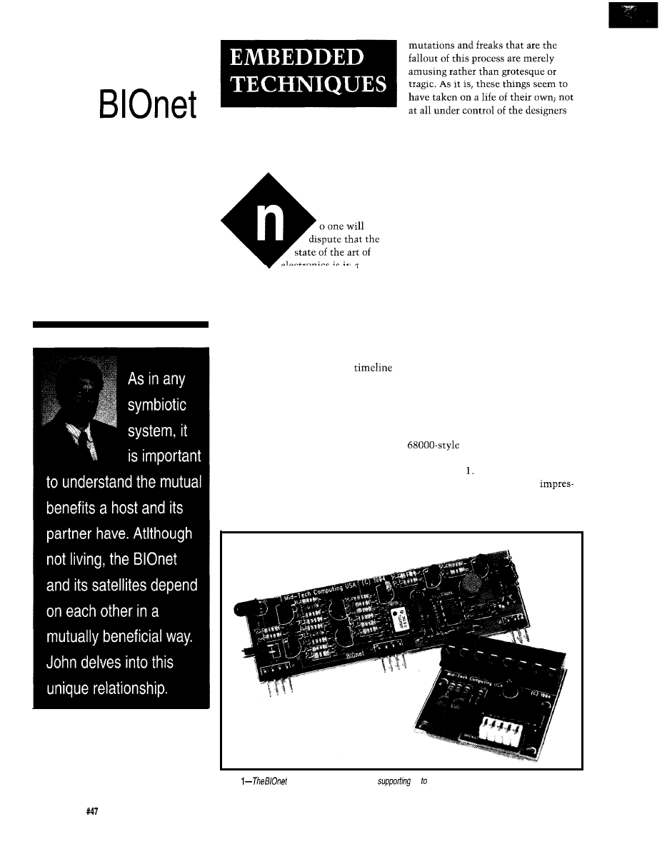
Reach Out
with
John Dybowski
and engineers that created them. To
illustrate the point, let’s start by
taking a look at the mother of bad
ideas.. .and a weird little controller.
electronics is in a
constant process of change. This fact is
even more evident in light of recent
developments that make it clear that
changes are occurring at an ever
accelerating rate. The evolution of
electronic products, in many ways,
parallels evolution in the natural
world. Due to the accelerated
on which this activity is transpiring,
we can witness the process of creation,
transformation, and extinction; the
process of natural selection, if you
will.
Fortunately we can take this all in
on a purely intellectually plane, devoid
OF DUBIOUS DESCENT
The bad idea of which I speak is,
of course, the diabolical segmented
memory architecture; its embodiment
dates back to the 8086 processor. This
much maligned departure from
conventional reason has caused
immeasurable discomfort to numerous
engineers and programmers over the
years. Now, in all fairness, segmenta-
tion itself isn’t really such a bad
concept but, let’s face it, a 64K
segment is ridiculous. I still remember
the time
I
was charged with the task of
developing my first 808%based control
system and how disappointed I was
with the processor, not at all what I
expected. Frankly, the way they were
touting this thing I expected some-
thing based more along the lines of a
architecture.
Then there was my first encounter
of any sentimentality or pathos, since
with the 803 This left me almost as
we are observing the struggle for
flat as my 8088 episode. First
survival involving only inanimate
sions are lasting, but with familiarity
objects. In this light, the resulting
comes a change in perspective. Now I
Photo
controller
card is capable of
up 30 satellites over long cable lengths.
74
Issue
June 1994
The Computer Applications Journal
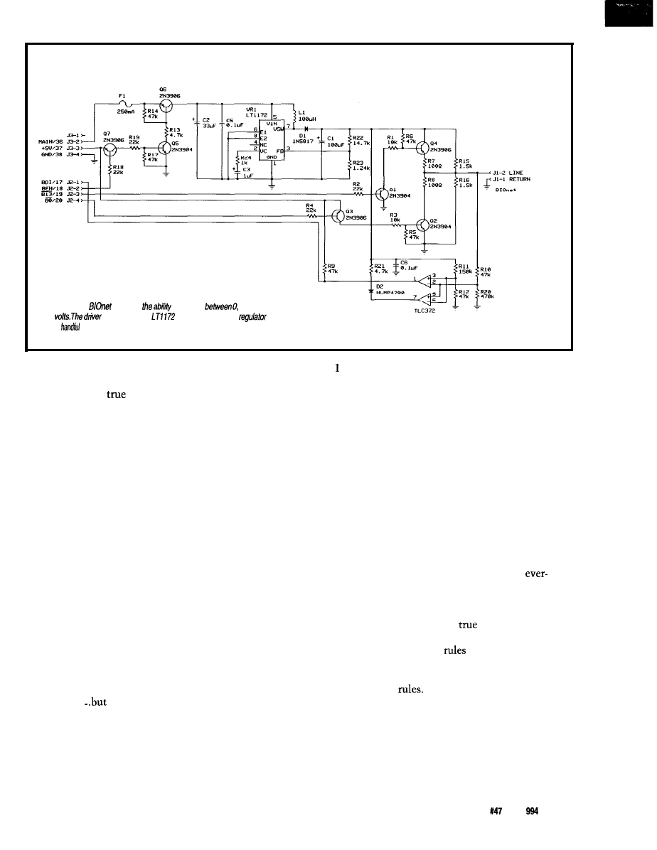
Figure l--The
requires
to switch
7.5, and
15
circuit uses an
switch-mode boost
and a
of
switching transistors to accomplish the task.
actually like the 803 1 and I don’t even
mind working with 8088 spinoffs that
much. Perhaps its
that we mellow
with age, but I can tell you that it
doesn’t hurt to place a good compiler
between yourself and your ugly
processor. These things were invented
for a reason! The 8031 is arguably the
most successful microcontroller
family in the world and the 8086 has
made quite a name for itself also.
Lucky thing I didn’t give in to my
initial ambivalence.
Several generalizations can be
made based on the transformations
that occurred to these basic processor
architectures. The case with the 8086
turned out to simply be a waiting
game until an acceptable implementa-
tion of the fundamental design was
finally realized. After the initial 8086
and then the abortive 80286, the 80386
finally signaled the long-awaited
arrival of a workable 8086 derivation;
big registers, big segments, and fixes
for most of the shortcomings of its
predecessors.
not all.
Ironically, one of the most
valuable features the 80386 possesses
is its ability to Nn the twisted and
constrained applications originally
coded up for the initial 8086. Obvi-
ously there are some social implica-
tions at work here. The 803 attained
great popularity, but the direction its
development took was entirely
different. It spawned a bunch of
derivatives although the fundamental
architecture has changed remarkably
little during its continuing tenure.
Perhaps, it just took the passage of
time to make the basic 8031 more
agreeable to a number of engineers.
I
know it worked for me.
You can draw whatever conclu-
sions you will from these observations,
but a couple of points seem quite
obvious to me. And these points are
equally valid when applied to elec-
tronic, software, or system design.
First, you define a manageable
feature set and pick a starting point
using whatever existing resources you
can most easily draw upon. A “man-
ageable feature set” implies that you
do some serious soul searching and put
some well-defined limits on your
enthusiasm. These limits must be
administered consciously and consci-
entiously since, obviously, the goal is
not to end up with a design that
appears in any way compromised. In
any case, unless you have enormous
resources, you’d be well advised to
watch those creeping features. Second,
and this is one of the fundamental
driving forces in engineering, is to
build on prior work. That this is an
irresistible force is made evident by
the fact that work is performed and
effort is expended on projects estab-
lished on foundations of dubious
merit. Undoubtedly, the architects of
the 80386 would have delighted in
abandoning backward compatibility,
but I’m sure the idea never crossed
anyone’s mind.
These two points form the basis of
a number of engineering disciplines,
particularly product engineering. And
it’s a direct result of these tenets that
the product development cycle is
capable of accelerating at an
increasing rate without vaporizing the
design team. Of course, blindly
adhering to any dogma can prove to be
perilous. The
art of engineering is
centered around knowing to what
extent the
should be applied and
when they should be dismissed.
You’ve got to know when to break the
COMPROMISING SITUATIONS
When beginning a new project, it’s
easy to get caught up in the excite-
ment of the moment. Often this
results in a lack of clarity and focus as
to what constitutes the important
The Computer Applications Journal
Issue
June 1
7 5
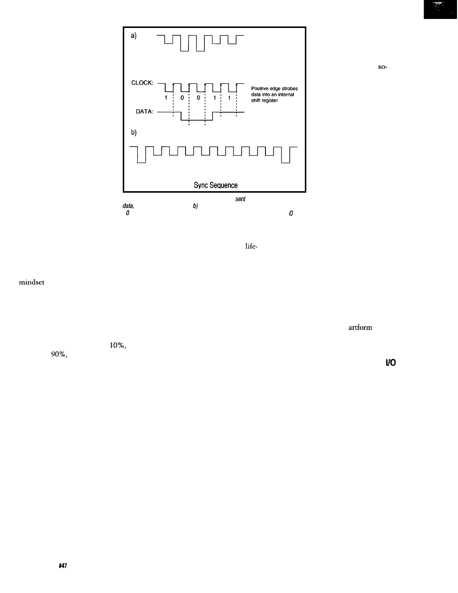
issues. It’s during this initial
phase that many projects
become doomed before they
even get off the ground.
Most often what happens
in these luckless undertak-
ings is that an inordinate
amount of features and
capabilities are inadvertently
specified. Regrettably, this
frequently results in a
protracted, sprawling design
cycle that quickly loses
direction and languishes
aimlessly for a seemingly
endless period of time. Of
course, the remedy is to show
some restraint when defining
the product’s capabilities.
This is easier said than done.
Otherwise, so many concepts
wouldn’t end up dying slow
deaths on the lab bench.
1 0 0 1 1
The Satellite would decode this into clock and data
0
1
1
1
1
1
1
1
1
0
Figure 2-a) Using three voltage levels, the signal
onto the network
contains
clock, and satellite power. Sending the satellite eight or more Is followed by
a causes synchronization. To avoid a false sync, it is a good idea to send a prior
to fhe Is.
Compromising a design may or
may not be difficult. A lot depends on
the nature of the product itself and the
level of sophistication of the antici-
pated audience, not to mention the
of the engineers. In any case,
you must match your product’s
capabilities to your intended customer
base. Obviously if 90% of your
customers will be happy with 10% of
the potential features, then the
particular situation should require no
further consideration; do the
forget the
then take your time
and work toward capturing the
remainder of the market.
Or better yet, refer them to your
competition. If your competitors bite,
it’ll keep them busy while you go off
and develop your next-generation
product line. Unfortunately, in reality
it’s usually not quite that simple and
generally much thought has to be
given to the relative merit of each
feature that is cut from the list. The
real trick is do it in such a way that
the end result is not perceived to be
deficient in any way. Done right, it
could actually enhance your product.
A somewhat related activity is the
ongoing improvement of an existing
product. We all know that this kind of
continuing development can exist to
fulfill several different objectives.
Most often this phase is entered to
It’s wise to remember
the pragmatic significance
of what we do as engineers.
Although we may take
pleasure in the efficient
rendering of an electrical
extend the usefulness of a product that
is on the declining slope of its
cycle. Alternatively, it could be to
round out a product that was initially
introduced with restricted capabilities.
Such restrictions could be intention-
ally imposed to satisfy the need to
make an early entry into the market or
to test the waters before committing
to a serious investment of dollars and
time.
Often this type of protracted
design activity results in a somewhat
meandering and apparently unregi-
mented mode of operation. Engineers
often have a lot of trouble with this.
The problem stems from the fact that
these things seem to have taken on a
life of their own and are not at all
under control of the designers and
engineers that created them. It should
not be surprising that disciplined
engineers would find such a state of
affairs somewhat disagreeable, but the
fact is, in many types of product
development, this is a normal and
natural progression.
circuit or find enjoyment in the
symmetry and balance of an algorithm,
this is, after all, fundamentally
utilitarian stuff that serves a higher
purpose. Perhaps this fact is most
easily appreciated by engineers
employed by small organizations
where the results of their labors can be
measured directly on the bottom line.
They understand that the art of
engineering is not an
but a
business proposition. And that’s the
way it is.
THE DISPERSAL OF DIGITAL
Acquiring digital data is usually
not a major undertaking. Usually you
take the outputs from your switches,
sensors, or probes and either wire
them to the system’s I/O port directly
or pass them through some intermedi-
ate level shifting, conditioning, or
isolation circuitry first. The problem
doesn’t becomes apparent until you a
have a lot of I/O points to service,
especially when dispersed over a
relatively wide area.
When looking at successful
In such a case, it’s usually imprac-
products, the important thing to
tical to run all those individual cables
remember is that although many of
back to the central controller so you,
these designs are flawed in some way
of necessity, end up with a networked
or another, these flaws don’t diminish
solution. In such an arrangement, the
their usefulness in the least. I’ve found
main controller talks to slaves that
some degree of fault with just about
handle their I/O in the outlying areas.
everything I’ve used in my design
This type of configuration most often
work. Many of these faults,
whether real or perceived,
were annoying enough to
make me mention them in
my columns. These
called faults usually become
perceptible only after
working with the particular
item for an extended period
of time. If we accept that
it’s because of familiarity
that these little inconsisten-
cies and imperfections
come to nag at us, it should
not be surprising that these
very elements seem so
magnified in our own work.
76
Issue
June 1994
The Computer Applications Journal
necessitates a multidropped data link
and a polled communication protocol.
With the current price of
purpose controllers, hardware cost at
first appears not to be much of an
issue, but the true currency of such an
arrangement is firmware complexity.
Personally, I prefer to have as few
processors per system as possible. Not
only does the code complexity escalate
when multiple levels of intelligence
are introduced, but there are
wide issues to address as well. Natu-
rally, the slave controllers need power,
and this power can be multidropped
along with the communications
cabling or supplied locally. Running
the power feed from the central site is
attractive, but depending on the line
lengths involved and the amount of
power the slaves dissipate, your IR
drops could spell trouble.
To prevent the above situation,
you would ideally want to drive a
relatively high DC level down the line.
This indicates the need for switch-
mode power supplies at the slaves.
Who knows where these things will
end up, so things such as power
monitor, a watchdog timer, and a good
reset circuit will undoubtedly be
required. Once you start looking at
what it takes to do it right, it does
tend to get a bit involved. Doing it is
easy and doing it right often require
orders of magnitude more effort. And
all you wanted was to acquire some
digital I/O.
A solution exists to this dilemma
in the form of the
binary
network that is hosted by the ec.25
embedded computer. Consisting of a
network controller card and multiple
remote satellite peripherals, the
network operates directly under
control of the system processor. The
controller card contains a 15-V switch-
mode boost regulator, power control
circuitry, discrete line drivers and
receivers, and an indicator LED.
Access to the distributed I/O is over a
single twisted-pair cable. This
lead cable is not only used for the
conveyance of bidirectional data, but
also supplies operational power to the
satellites as well.
The satellites themselves are
addressable peripherals and provide
l
CPU
l
Eight
Inputs
l
High Speed Floating Point
l
Four
Inputs
l
32K Nonvolatile RAM
l
Four
Drivers
l
16K EPROM Programmer
l
12 Diagnostic Lamps
l
RS-232
Printer
l
Extensive Surge Protection
l
Watch Dog Timer
l
Vdc Power
l
Sell Compatible 262 Modem
l
Clock/Calendar
l
32 Counter
l
The Datrax 52 is a computer aimed
primarily for data acquisition, process
control,
a n d g e n e r a l S C D A
applications.
A target and
POINT
BASIC on a single
board. For a complete
description please
call or FAX.
Track Svstems
KY 42301
Phone
926-0873
FAX
CORPORATION
i
i
ii
DR
1
i
S PRICES
ON ITS
51 PRODUCTS
i I
All of
boards have 32K
32K monitor EPROM, with all the system signals
available on
Our boards
with complete documentation, including a guided
tour of the software and hardware, sample programs, and a full set of
circuit diagrams.
In
the boards come standard with our own
software development
system, READS.
to an IBM PC or compatible host, READS allows
assembling,
and running
software in the MCS-51
1
1
the
family in the
DIP format, including
8052
family or for
use
or
embedded
1
(actual size 3.5’ by 4.5’)
28 total I
Ports,
conversion,
2-way reset
access to all
vectors, (actual
assembly
No
knowledge of
control or
1
skills are needed with
Please contact us for more
on our
of products.
Price for our boards and software now start at $85
1
1
CORPORATION, P.O. BOX 90040, GAINESVILLE, FL 32607
PHONE: (904) 373-4629 BBS (904)
The Computer Applications Journal
Issue
1994
77
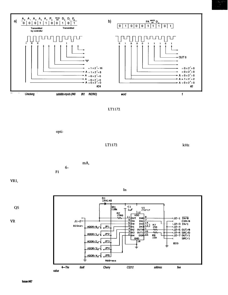
by CS 212
1
1
0
0
0
1
DATA PARITY
IN
1 STATUS
IN 0 STATUS
FOR READ
ADD. PARITY
A
BINARY=
A, A, A, A, A,
D, PD
DATA PARITY
O U T 1
‘1’ FOR WRITE
ADD. PARITY
A
A
BINARY=
Figure 3-a)
Me status of the
and
or
requires that
a read
be sent. b) Conversely, if one wishes to update Out and Out 0, a
write word is sent to the satellite.
two binary inputs and two binary
the Maxim MAX733 regulator and not
event, the regulator is operated
outputs each. Up to 30 satellites can
occupy the cable at one time. It is
possible to maintain reliable operation
over very long cable lengths using such
an arrangement, but this particular
implementation is especially
mixed for low-power operation, thus a
maximum cable length of about 500
feet is specified. What’s involved in
this basic configuration is shown in
Photo 1.
The BIOnet controller card is
depicted schematically in Figure 1.
Linear Technology’s
that I’m
presently using. Unfortunately,
although the MAX733 is a solid
performer in protected settings and it
does very well in applications such as
flash programming, it turns out be
much too fragile for the harsh duty
involved in driving long lines into the
outside world. The
has held up
remarkably well through the rigors of
my network testing and, although not
a micropower regulator by definition,
at 6
it isn’t exactly a power hog
entirely under processor control, so the
high voltage doesn’t have to be kept on
for any length of time, at least not
when using the BIOnet for input.
The LTl172 is a current-mode
switcher that allows pulse-by-pulse
current limiting to provide a high
degree of switch protection. Punning
at a fixed frequency of 100
allows
the use of a relatively small inductor
and filter capacitors even when
operating in continuous mode. Boost
regulators are not inherently protected
Unregulated power (in the range of
either. And anyway, reliability is the
against short circuits. This isn’t a
10 V) is carried through fuse to Q6
key parameter here. Running a boost
result of any design deficiency on the
which ultimately controls power to
regulator can be expensive in terms of
part of the regulator itself, but is due
the LTl172 switch-mode boost
input current, so the added quiescent
to the fact that the steering diode
regulator. When the processor wants to
dissipation doesn’t really present
directly connects the input to the
energize the network, it pulls the port
much of an additional burden. any
output.
pin that drives Q7 low.
This action biases Q7 on
and provides base drive
to
which, in tum,
drives Q6 into satura-
tion supplying power to
1 which supplies
high voltage to the
system.
You may recall that
several columns back I
presented photos of the
cards that make up the
ec.25 embedded com-
puter system. Observant
readers may have
+
RETURN
Jl-1
L I N E
J E - 2
Con/l
J t - 8
Satellite
noticed that the original
BIOnet card contained
Figure
satellite
is bawd on the
Semiconductor
S-ART. The node’s
is set using
jumpers to
a
in the range of O-29.
78
June 1994
The Computer Appliitions Journal
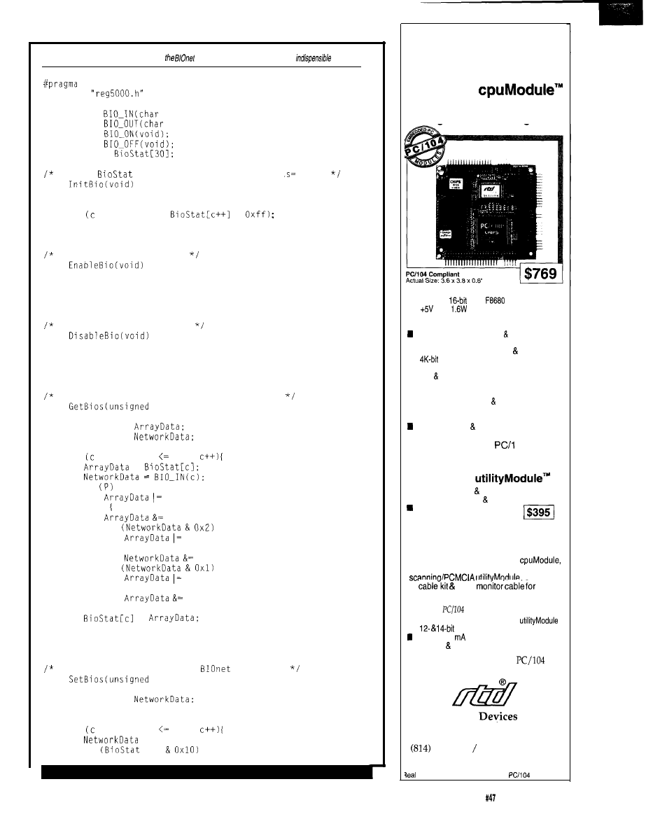
LARGE
CODE
i/include
extern char
address);
extern void
address, char value);
extern void
extern void
unsigned char
Default
array to: outputs= off. input
void
fault
Listing
l--Support services for
binary network include only the most
functions.
unsigned char c;
for = 0; c < 30;
=
return;
Turn on the network power
void
BIO_ONO;
return;
Turn off the network power
void
BIO_OFFO;
return:
Get the inputs of multiple BIOnet satellites
void
char start, unsigned char end)
unsigned char
unsigned char
unsigned char c;
for = start: c end:
=
if
0x4;
else
Oxfb:
if
0x2;
else
Oxfd
if
0x1;
else
Oxfe;
=
return:
Set the outputs of multiple
satellites
void
char start, unsigned char end)
unsigned char
unsigned char c;
for = start; c end:
= 0;
if
[cl
(continued)
Replace Four
Conventional PC/l 04
Modules with
One
CMF8680
Embedded PC/XT Controller with
Intelligent Power Management
n PC/XT compatibility with 286 emulation
n 14 MHz,
C&T
CPU
n
only;
at 14.3 MHz, 1 W at 7.2 MHz
n Intelligent sleep modes, 0.1 W in Suspend
n ROM-DOS and RTD enhanced BIOS
Compatible with MS-DOS real-time
operating systems
n 1 M bootable solid state disk free software
n
configuration EEPROM (2K for user)
n 2M on-board DRAM
n IDE floppy interfaces
n CGA CRT/LCD controller
n Two RS-232 ports, one RS-485 port
n Parallel, XT keyboard speaker ports
n Optional X-Y keypad scanning/PCMCIA
interface
Watchdog timer real-time clock
Expand This Or Any
04 System
with the
CM1 06 Super VGA
Controller
n Mono/color STN TFT flat panel support
n Simultaneous CRT LCD operation
Resolution to 1024 x 768 pixels
n Displays up to 256 colors
Speed Product Development with the
SK-CM1 06-X Starter Kit
Your kit includes the CMF8680
CM106 SVGA controller, CM102 keypad
CMF8680
VGA
just
$1295.
Additional
compliant modules from RTD:
n CM1 04 1.8” hard drive carrier
n
analog I/O modules
12-bit, 4-20
analog output modules
n opto-22 digital I/O modules
For more information on our
and
ISA bus products, call today.
Real Time
USA
200 Innovation Blvd.
l
P.O. Box 906
State College, PA 16804 USA
234-8087 Fax: (814) 234-5218
RTD Europa
l
RTD Scandinavia
Time Devices is a founder of the
Consortium.
33
The ComputerApplications Journal
Issue
June
1994
79
The fuse feeding the
input is the simplest way of providing
protection against the effects of serious
line faults on the network or circuit
malfunctions. A related limitation of
the boost topology-and this is also
related to the conductive path the
steering diode provides-is the
inability to implement a true power
shutdown feature within the regulator.
Naturally, it is possible to stop the
regulator from outputting a stepped-up
voltage, but a voltage (equal to the
input voltage minus the drop across
the diode) will still be present on the
output. Often this isn’t a problem, but
obviously here it would be disastrous.
The front-end switching transistors
eliminate this problem using the same
brute-force mentality that resulted in
the deposition of the protective fuse on
the card. Evidently, finesse and boost
regulators don’t mix.
Once the high voltage is enabled,
the processor is free to switch 15 V,
ground, or 7.5 V onto the network. It’s
through the manipulation of these
voltages that data is transmitted and
Listing
0x2;
if
[cl 0x8)
return:
Assembler linkage: Read the inputs of a BIOnet satellite
static char
char address)
extern void
unsigned char value;
ACC = address;
value = ACC;
return (value);
Assembler linkage: Write the outputs of a BIOnet satellite
static void
(unsigned char address, unsigned char value)
extern void
ACC = address:
B = value;
return:
l
1 2
Year Warranty
l
Support by
phone
l
30dayMoneyBackGuarantee
l
FREE software
via BBS
l
l
2716
l
Flash
(EMP-20 only))
Micros
.
GAL. PLO
from NS.
NEEDHAM'S
4630 Drive, Suite
Sacramento, CA 95838
.
pm PST)
BBS
Fax (916) 924-8065
oes your Big-Company marketing
department come up with more ideas
than the engineering department can
cope with? Are you a small company
that can’t afford a full-time engineer-
ing staff for once-in-a-while designs?
Steve Ciarcia and the Ciarcia Design
Works staff may have the solution. We
have a team of accomplished program-
mers and engineers ready to design prod-
ucts or solve tricky engineering problems.
Whether you need an on-line solution for
a uniaue
a product
for a startup
or
just
sulting, the Ciarcia
Design Works is ready
to work with you. Just fax me your
problem and we’ll be in touch.
The Computer Applications Journal
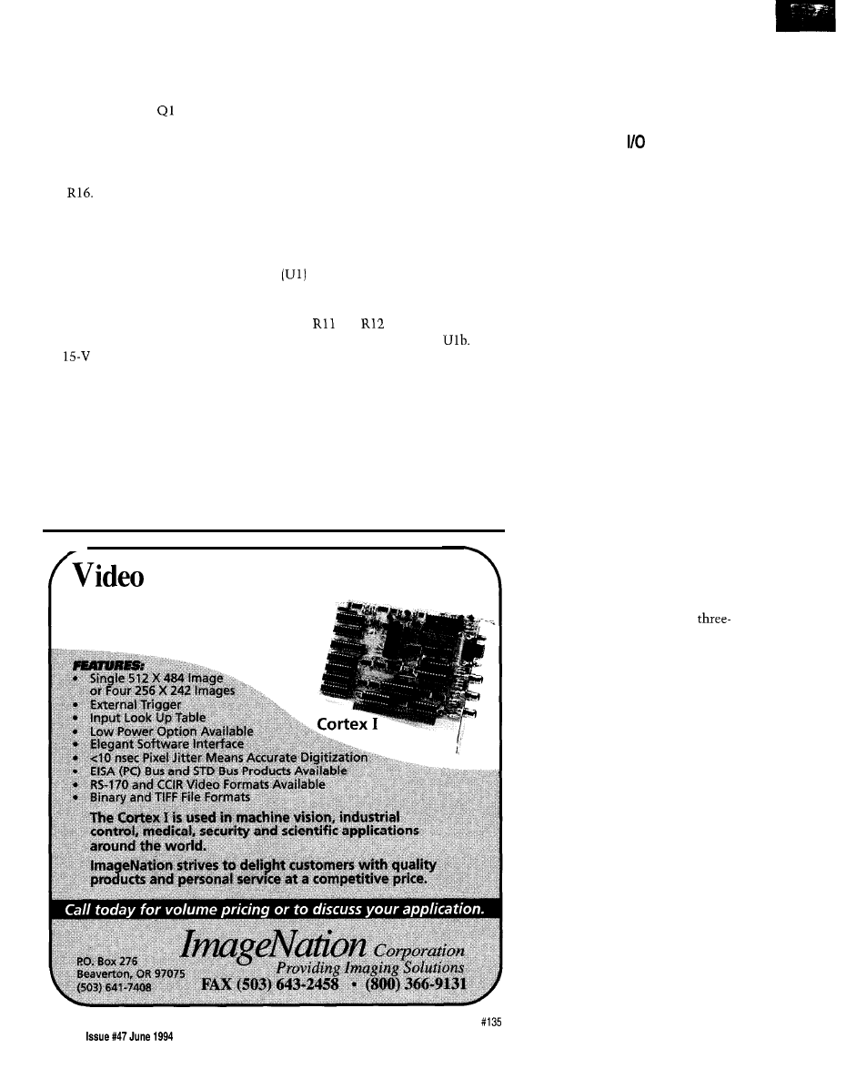
received and power is supplied to the
satellites. The line driver, constructed
of discrete transistors, delivers these
voltages to the line.
and Q4 form
the high-side switch and Q3 and Q2
switch the ground leg. When 7.5 V is
required, the line is held passively by
the voltage divider composed of R15
and
This arrangement is appropri-
ate for the low-power operation needed
in this setting and the performance is
adequate to meet the specified maxi-
mum 500-foot line limit. If you were
to try to drive much longer lines, you
would find the limiting factor to be the
7.5-V resistor divider.
Looking at how the various
voltages are sequenced, you’d see that
the
rail is actively driven by the
controller and that both the controller
and the satellite have the capability to
actively establish a ground potential.
The 7.5-V level is always preceded by
15 V, but here, with long cable lengths,
the line capacitance can make for a
very lazy transition when using just
the resistor divider. If you continue to
extend the cable, you eventually reach
a point where the waveshape gets so
distorted that the satellite no longer is
able to properly discern the logic
levels. The answer to this problem is
to supply a 7.5-V emitter-follower that
is momentarily turned on to hasten
the 15-V-to-7.5-V transition. In any
case, this is of no consequence here
since I’m unwilling to budget the
slugs of current needed to ensure
robust operation over very long cable
lengths.
The TLC372 voltage comparator
is used to discriminate the
presence of logical ones and zeros from
the satellites nodes. A reference made
up of and
provides approxi-
mately 5 V to both Ula and
The
output of Ula is sampled when the
line is relinquished to the control of
the satellite. What happens is the line
is released and is held at 7.5 V by the
divider and the satellite will either
leave the line alone to indicate a one
or pull it to ground if it wants to assert
a zero. You can see that the threshold
level itself is not extremely critical in
this application. The other half of this
Frame Grabber
l
$495 lncludina Software with “C” Librarv
l
Half Slot Card-for Compact Applications-
* Real Time Imaging with Display Output
l
8 Bit (256 Gray Levels)
IC is used to drive the low-current
indicator LED to show network
activity and indicate the presence of
network power.
ADDRESSABLE
Now that I’ve described how the
line is manipulated, let me work
backwards and tell you how these
levels are actually used. The BIOnet
satellite works on the principle where
an address is sent over the two-wire
cable. The satellite that recognizes the
address then responds in accordance
with the command that follows. Since
we’re only dealing with two inputs and
two outputs, it follows that a limited
command repertoire exists. The
satellite can be instructed to transfer
the received data to its outputs or to
respond with the status of its two
inputs.
Communications are established
by dividing the line signal into three
levels that are used to provide a time
signal for synchronization and a data
signal that carries the actual address-
ing, commands, and data. As I men-
tioned before, these three voltage
levels are defined as 15 V, 7.5 V, and 0
V. This signal is also rectified and
filtered and is used to power the
satellites. Figure 2a shows the simple
method used by the BIOnet satellite to
derive ones and zeros from the
level signaling scheme. The method
for establishing synchronization is
shown in Figure 2b. Not only does this
continuous pattern of ones establish
the internal synchronization of the
satellites’ data recovery circuitry, but
also pumps power down the line that
the satellites rectify and store for use
as a local power source.
Having established a means of
denoting and deciphering ones and
zeros, Figures 3a and 3b show how
they are combined to construct data
packets that are ultimately used to
transport meaningful information. The
first transaction shows a read sequence
in which the satellite responds with
the status of its two input bits. The
second transaction shows how you’d
format a message to update the status
of the satellite’s two output bits. Both
of these sequences incorporate parity
bits in order to detect line errors.
8 2
The Computer Applications Journal

Parity is appended to the address
sets the initial default status for all
portion of the message and to the
input and output bits for the defined
command/data portion as well. In both
satellites. The outputs are set to off
cases, the parity must test even for the
and inputs are defined as in fault
transaction to complete.
status.
If a parity error is detected on a
write command sequence, then the
transmission is disregarded and the
output bits remain unaffected. If a read
command is received with bad parity,
the satellite will respond with three
one bits. That is, the satellite will
force a parity error in its transmission
so as to inform the controller that a
communications problem had been
encountered. The parity-based error
trapping combined with robust
electrical performance provides an
adequate data link for the transfer of
binary I/O. However, with anything
this simple, you must be sure not to
exceed its capabilities.
Shown in Figure 4 is the sche-
matic of the circuitry contained on the
satellite card. Five jumpers set the
address to a number in the range of
29. Two outputs with a drive capabil-
ity of 1
can be used for driving
low-current
optocouplers, or
optoisolated relays. The two inputs
normally would be used to monitor
contact closures. All signals into and
out of the satellite must be isolated to
ensure proper operation.
Get B i o updates the array entries
for the indicated satellites. These
satellites must be contiguous and are
specified as a number range (which is
usually the way you’d further populate
the network anyway). The assembly
language driver is invoked to return
the status of a single satellite. If a
parity error is detected, the fault bit is
set and no further bit manipulations
need be performed. Otherwise, the
input bits are moved into the appropri-
ate positions in the respective array
byte. The routine continues until the
specified range has been serviced.
et
operates similarly and writes
the value of the output bits contained
within the array to the specified
satellites. Again, the assembly routine
handles the actual transfer of data.
Unfortunately, space limitations
prevent me from presenting the
gruesome low-level assembly driver
that actually makes the communica-
tions happen at this time. I’ll conclude
next month with the grisly details.
q
Listing 1 shows the fundamental
support package for the
As
usual, only the most indispensable
functions are included here. A global
array is defined that holds
the status of the entire network.
Obviously, if fewer than 30 satellites
are required, a smaller array can be
defined. In any case, the three lower
bits of each byte are reserved for its
respective satellite’s input status.
Dybowski is an engineer in-
volved in the design and manufacture
of hardware and software for indus-
trial data collection and communica-
tions equipment. He may be reached
at
For elements of this project, contact:
Mid-Tech Computing Devices
P.O. Box 218
Starting with the least-significant
bit, the bits are set aside for the input
bit status and S2 and fault status.
When the fault bit is set, this indicates
the satellite is in a problem condition
or is not present. In this case, the
and S2 bits are meaningless. The next
two bits contain the Cl and C2 output
status. These bits are manipulated by
the firmware and indicate the desired
state of the outputs. En a bl
o and
D i s a b 1 e B i o turn the high-voltage
network supply on and off. I n i t B i
o
Stafford Springs, CT 06075-0218
(203) 684-2442
Individual chips are available from
Pure Unobtainium
13 109 Old Creedmoor Rd.
Raleigh, NC 27613
Phone/fax: (919) 676-4525
.
422 Very Useful
423 Moderately Useful
424 Not Useful
1994 120 page catalog for PC, VME,
and
data acquisition. Plus infor-
mative application notes regarding
anti-alias filtering, signal condition-
ing, and
more.
NEW Software:
and more
NEW L
OW
Cost
Boards
NEW Industrial PCs
NEW Isolated Analog and
Digital Industrial
New from the inventors of
plug-in data acquisition.
Call, fax, or mail for your
free copy today.
A D A C
American Data Acquisition Corporation
70 Tower
Office
Park, Woburn, MA
01801
Phone:
648-6589
Fax:
(617) 938-6553
The Computer Applications Journal
Issue
June 1994
83

The Circuit Cellar BBS
bps
24 hours/7 days a week
(203)
incoming lines
Internet
With the huge increase in message traffic since making our connec-
tion the Internet, I’ve had renumber the message base again, so
we’re back into low message numbers. What had been an occasion
that happened only once every two years or so is now something
that’s happening every few months.
In this month’s first thread, we take a quick look at what’s
necessary to code a soft system reboot on an
Next, we look
at input protection for an
converter. Finally are some suggested
enhancements the Vertical Blanking Interval Explorer project
published a few months ago.
soft reboot
8558
From: MARK SERBU To: ALL USERS
Does anyone know of a soft reboot routine for the
1
family? In particular, I’m trying to reboot upon
reception of a certain character in my
interrupt
routine. I tried simply jumping to the initialization section
of the program which just places all the reset values in the
and memory, but it didn’t work. Before I bust my tail,
I figure I’ll ask the masses. Anyone ever try this? Thanks.
Msg#: 8574
From: GARY CORDELLI To: MARK SERBU
Actually, I have done this and *almost* all I did was
LJMP to the reset routine. I was doing much the same thing
as you want-on receipt of a software reboot command via
the
interrupt, I wanted to just do the same things
that reset did. Since my reset routine did not actually
reinitialize things I knew would be initialized by the actual
RESET of the processor (e.g., set all port pins high, clear
most of the
I had my
parser do this on receipt
of the software reboot command
in my case).
Remember this includes setting the Stack Pointer back
to
as RESET does. The trick that is probably screwing
you up is to remember that a
interrupt (i.e., RI
resulting in a serial interrupt) got you to the place where
you are trying to call your reset routine, so you need to
acknowledge (“clear”) this condition or no further inter-
rupts will ever occur in the “new incarnation” of your
program. So, just before you do the “LJMP
do
a “CALL ClearInt,” where
is a line that just says
like so:
84
Issue
June 1994
The Computer Applications Journal
This is the serial interrupt code
Determine you have a RI rather than a TI
Determine that you received the reboot code
Initialize all
as per 803 1 manual (RESET
including Port Pins and Stack Pointer, etc.
call ClearInt
ClearInt:
ljmp
This looks dumb, but it will work-I’ve done exactly
this. The thing that gets you is that you “think” you’ve
reset everything when you initialize all the
and other
devices, but the internal state of the processor is still telling
the 803
1
interrupt logic that it is servicing a serial inter-
rupt, so you can’t ever get another serial interrupt or any
lower-priority interrupt to be recognized again!
Hope this helps you out of your bind.
8666
From: MARK SERBU To: GARY CORDELLI
Hey, thanks. I thought I took care of the interrupt
problem when I reset the IE register, but you’re right that I
did leave the call to the
routine hanging (no RET1
instruction). I’ll try again.
8691
From: GARY CORDELLI To: MARK SERBU
Yeah, I might not have made that really clear, but the
“reinitialization” section that is meant to mimic a “real”
RESET was assumed to do a “MOV IE, #OOh,” but that just
disables all future interrupts until the EA bit and any other
interrupt enable bit is set. Without executing a
instruction, though, even ‘after* you reenable your inter-
rupts with IE they will *not* be recognized! If you weren’t
doing that
you were dead in the water from that
point on as far as interrupt response goes. It sounds like the
addition of that little “NULL” interrupt call (you need to
execute an actual
instruction and the simple way to
do that is simply to “CALL” to the address of a “dummy”
RET1 instruction. Poof! Like magic.
Now, if only every seemingly ugly problem had such a
simple solution!

8896
From: MARK SERBU To: GARY CORDELLI
Thanks again, Gary. I was wondering how to stick that
RET1 instruction in there. I was thinking of borrowing a
trick I learned from 8086 assembler interrupt routine stuff,
which is to push the address of where you want to go onto
the stack and then execute a return (or
in this case). I
still haven’t gotten around to trying it, but if your call
works, what the heck?
Msg#: 9107
From: MARK SERBU To: GARY CORDELLI
Since I sent the last reply I have gotten the reset
routine to work. I had to use the trick of pushing the DPH
and DPL of the initialization routine onto the stack and
doing a
and it works great. I’m curious about your
call method, just for future reference.
9153
From: GARY CORDELLI To: MARK SERBU
Your method is fine, too. Basically, the 805 1 internal
state machine just needs to be told that the serial interrupt
routine it
running up until you decided it had parsed
out a “restart” command has been completed. For all the
other serial interrupt cases, a RET1 was eventually ex-
ecuted. All you need to do to have any interrupt routine
“return” to somewhere other than the interrupted instruc-
tion is to perform a RET1 ‘without
l
returning to the
address currently pushed onto the stack. If you change the
return address this way, you can RET1 to the new “return
address” that you push on the stack in its place.
The trick I use is just a bit more tidy if not as obvious
(everyone should know what a PUSH, PUSH, RET
does..
they may ask why it’s being done in this spot). By
the same token, they may ask why make a CALL directly to
a
Anyway, since you have a label referencing the
location of the new “return address,” simply do an LJMP
to it. since the LJMP alone only satisfies one of the criteria
(get me to the right place), I make a CALL to a
instruction just before the LJMP to satisfy the second
criteria (clear the “I’m-in-a-serial-interrupt” state). This
results in three lines of code:
DummyRETI
l j m p
DummyRETI:
The PUSH, PUSH, RET1 satisfies the same two criteria.
The PUSH, PUSH sets you up to get to the right place,
while the RET1 clears the interrupt state. It is just as good
even if it looks a little messier:
mov dptr, #WhereToGo
push dpl
push dph
Every decent programmer knows where your
sends your program, but even an idiot programmer can see
where the LJMP goes. The call to DummyRETI can be
commented in-line with a “just to clear INT state” to make
its intent obvious even to novices. That’s about the only
benefit to the method I use that I think is worth mention-
ing (I’m not going to nit-pick about the difference of line,
2 bytes, or 2 cycles-big deal! You’re about to reset the
whole darn thing..
got the time!): program mainte-
nance ease makes the difference. I recommend it. Espe-
cially since I’ve been on the receiving end of a lot of code
that was not written to be easily maintained, and I had the
task of making a “simple little mod” to it-oh boy. :-)
Good luck with the rest of your project.
Input protection
7623
From: GARY OLMSTEAD To: ALL USERS
I am designing a circuit that takes O-5 VDC input from
an environment that can potentially have several hundred
volts on it for an indefinite period of time. (In other words,
these aren’t necessarily transients; the inputs could be
wired direct to the 120-VAC power lines. Presumably
accidentally, but..
I don’t have to sense anything in these circumstances; I
just have to avoid burning up.
Most of the usual input protection
zeners, etc.-are aimed only at transients. Somewhere,
heard a mention of something called a PTC, positive
resistor. Are these good for this purpose? If so, who
makes them, and how do use them? If they aren’t good,
what is better?
7718
From: LEE STOLLER To: GARY OLMSTEAD
A resistor feeding a 5-V zener to ground may be all you
need to do what you want.
7722
From: JAMES MEYER To: GARY OLMSTEAD
No. They aren’t.
All you have to do is to make sure you are limiting the
current that your device will draw when it’s connected to
the 120 VAC. There are some new devices that are quite
The Computer Applications Journal
June 1994
85

TIME
good at limiting current. They are called “resistors.” They
resist current.
If you add a resistor or two between the stuff that
you’re measuring and your measuring circuit, then you can
use a zener to limit the voltage *at your measuring circuit
The applied voltage can go to 120 volts and your circuit will
still be safe.
Msg#: 8297
From: PELLERVO KASKINEN To: GARY OLMSTEAD
PTC resistors are probably available from every maker
of NTC resistors. Philips comes to mind. But you do not
need to go any further than a Digi-Key or Newark catalog.
In fact, I just checked my Newark catalog and they carry
both Philips and Keystone.
And, yes, they are great for the purpose you are describ-
ing. In fact, I think they are so great that somebody filed a
patent application for an RS-232 interface protection
scheme using them plus Transzorbs. The Transzorbs do the
first-line protection against any fast transient, being in
parallel with the port, while the PTC resistors are in series,
thereby limiting the long-term overload that would damage
either the IC or the Transzorb.
The reason a PTC resistor is good for the described
application is that there is almost no current through the
resistor as long as the signal levels are ordinary, but there is
plenty when the Transzorb starts clamping. This current is
what heats the PTC resistor and once it reaches a transition
temperature (something in the
range), the resis-
tance within just a couple of degrees increases by orders of
magnitude. With the higher resistance, less current equals
less heating of both the Transzorb and the PTC resistor.
Circuit saved!
Msg#: 8415
From: JAMES MEYER To: PELLERVO KASKINEN
The only problem with PTC resistors for the applica-
tion in question is that the application was involved with
*analog’ signal input protection. You’re talking about a
*digital
l
signal input.
PTC resistors are useful because they change resistance
with temperature. PTC resistors are a component that you
do *not * want associated with the input circuit for analog
signals unless
able to accept the resulting degrada-
tion of the overall accuracy.
8904
From: PELLERVO KASKINEN To: JAMES MEYER
Hmm-I think I realized the question was about an
analog circuit. Of course I failed to emphasize that the
protection takes place well above the operating voltage.
And there is a minimal change within the operating signal
86
Issue
June 1994
The Computer Applications Journal
range, as the PTC resistor only starts heating when there is
some real current running through it. That again happens
only after the zener or Transzorb becomes conductive.
Let’s see. Was it O-5 V? So, the signal input impedance
within that range is approaching infinity. It may become
lower above 5 V, but only when the, say, 6.8-V Transzorb
starts conducting is there any current through-oh, maybe
1
kilohm PTC resistor. No detrimental effect to the signal
with
1
k versus infinity voltage divider. The Transzorb
protects the input above 6.8 V where you do not care if it is
not linear anymore. And the PTC resistor protects itself,
the Transzorb, and the signal input port with continued
overloads up to maybe over 100 V. Now, I do not claim
there would be absolutely no detrimental effects. If the port
has to be very fast, the RC will have an effect. And there
may be varying amount of capacitance in the Transzorb
with different voltages, but that is just one of the engineer-
ing challenges, isn’t it?
9097
From: JAMES MEYER To: PELLERVO KASKINEN
Exactly why I thought the PTC resistor was unneces-
sary and, when employed without proper consideration,
detrimental to the accuracy of the circuit.
It is unnecessary to draw *any* appreciable current at
the input to protect it. If you choose a stable (ordinary)
series resistor large enough to limit the current at the input
and parallel the A/D converter input with an ordinary zener
diode, then you can eliminate the PTC resistor and all the
problems associated with choosing the “correct” one.
In other words, pick a series resistor large enough to
equal or exceed the value of the PTC resistor ‘after* it has
been heated, and you have eliminated the necessity to heat
the PTC resistor at all! Plus, there is no ambient tempera-
ture factor to figure into the equation.
In most cases, a simpler solution is a better solution.
Often, engineering parts *out * of a design is more impor-
tant than engineering parts *into* a design.
Msg#: 9217
From: BRAD SANDERS To: JAMES MEYER
Be careful here..
.a
zener is a
device (they all
are), and still draws current when “off.” This leakage
current can cause all kinds of accuracy problems, especially
when teamed with a large “protection resistor.” This
amounts to an increasing current at increasing input
voltages, causing a (possible) compression of dynamics. I
don’t know what accuracy this is going for, but given the
varying quality of zeners, and the
capacitance
of
(another reason to be wary of limiting resistors
-directly_ on ADC inputs), one could end up with a very
expensive
A/D converter!

Better to design the op-amp stage
the ADC
well, and protect the signal
it gets to the (much
easier to drive) buffer. There is a very good discussion of
these considerations in the Crystal Semiconductor
databook.
And yes, I find it
is preferable to reduce
circuit complexity..
when it comes time to fix it!
Msg#: 9372
From: JAMES MEYER To: BRAD SANDERS
OK. Let’s look at the problem. Many A/D converters
need to be driven from a low-impedance source to achieve
their rated accuracy. That’s true even though the ADC
input may have a very high input impedance on its own. In
any event, it’s just “good design” to buffer the ADC input
with an op-amp on general principles.
That said, we *still* have to protect the op-amp input
from overvoltages. Let’s say we’re using an op-amp in the
noninverting, unity gain, buffer configuration. The input
impedance of the op-amp will be very high. Let’s assume
that the input voltage range the A/D converter will need to
work over is O-5 volts. Let’s also plan for the circuit to be
fail-safe if it’s connected to 120 volts AC.
If we use a
zener diode at the input to the
amp, the
reverse breakdown will provide one limit
and the forward conduction of the zener will provide the
protection from the negative peaks of the AC that we’re
protecting against.
Let’s say we choose a
zener. We will
need to limit the current to something that won’t hurt the
diode. If we dissipate 100 milliwatts, that should be safe.
With 100 milliwatts at 6.8 volts, we should limit the
current through the zener to 15 milliamps. With
volts
applied, ohms will limit the current to the proper value.
Let’s use
ohms in series just to be sure. Besides, I can
design *anything* using resistors that decade multiples of
:-)
Most modern silicon zeners have *much* less leakage
below the breakdown knee than microamp, but let’s use
that as a worst-case figure. If you multiply
ohms by 1
microamp, you come up with 0.01 volts. That 0.01 volts is
part in 500 of a
signal. Equivalent to about 1 LSB of
a
digital value.
Reduce the
series resistor to Sk ohms for 168
milliwatts of dissipation in the zener, and you reduce the
error to one LSB of a
number.
Msg#: 9871
From: PELLERVO
To: JAMES MEYER
I agree with most of your conclusions, but because I do
not know what actual circuit the original issue was dealing
with, I cannot exclude the possibility that it does draw
current. Could for that matter be an ordinary TTL
gate input.. Anyway, there still is a reason why a PTC
resistor could serve better than the fixed high resistance.
And I think I pointed toward that reason in my previous
message. That is the RC effect that might distort the
normal operation if the R is made large enough to properly
handle the overload condition. But again, I agree with your
conclusion in most of my own designs-I’ve never used a
PTC resistor in this fashion yet. I just decided it was worth
remembering this sneaky way in case I someday am going
to need it.
Msg#: 9079
From: STEVE CIARCIA To: LEE STOLLER
One thing that nobody seems to have mentioned is still
very important. That is the input impedance of the A/D
converter. With all this series resistance and parallel
protection, make sure the ADC impedance is high enough
that there is no effect on the measured voltage. Remember,
if you drop 1.2
across the series resistor, that is 1 bit on
your
ADC. Coincidentally, we just went through this
whole scenario on the design of the new
ADC
on
2000. It has lots of protection, but needed
the addition of an instrumentation amplifier to raise the
impedance enough so the series protective resistance
“seemed” minuscule by comparison. Of course, adding the
instrumentation amp also gave it some nice features like
programmable gain too. Be careful. Few people seem to
realize that adding that “zener and resistor” or “resistor
and MOV” can also add about 10% A/D error on some
chips.
9118
From: LEE STOLLER To: STEVE CIARCIA
Of course you’re right..
for many simple problems,
the simple solution is what you want. That’s what I tried to
provide.
If you are concerned with a general-purpose,
precision
that’s a *complex* problem.
“To every complex problem, there’s always a simple
answer-and the simple answer is always wrong.” H. L.
Mencken
Msg#: 9227
From: JAMES MEYER To: STEVE CIARCIA
The ADC impedance doesn’t have to be high as long as
it is known and stable. Once you know the input imped-
ance, you can figure out the scale factor introduced by the
series impedance.
That’s the reason that I came down so hard on the PTC
resistor idea. You will never be sure exactly what the
resistance of a PTC resistor will be.
The Computer Applications Journal
Issue
June 1994
8 7

9369
From: JAMES MEYER To: LEE STOLLER
That quote from Mencken is pretty simple. Does that
mean that it’s also wrong?
Vertical blanking interval continued
From: DAN HOPPING To: MIKE BARNES
Mike, nice article! Neat circuit design! A couple of
questions you may have thought about and or already
answered.
1. Did you look at the possibility of decoding Vertical
Interval Time Code (VITC) with your circuitry? I realize
you would have to speed up the clock since the data
throughput is higher, but it looks doable at a glance.
2. I’m now wondering if a circuit (similar to yours)
might be designed to add closed captioning or other custom
data to video.
By the way, did you make a circuit board for your
project or is it point-to-point?
From: MIKE BARNES To: DAN HOPPING
The VBI Explorer won’t decode VTIC directly, but it
shouldn’t be too hard to implement. Basically, it works
similar to the network time code except the clock speed is
different (I’m not sure what the speed is; it appears about
25% faster than the network time code] and the format is
different. You might be able to get away with just changing
X2 to the correct value and making software changes for the
new format.
Generating closed caption signals would be a fairly
involved project. You would need to write software to
convert the captioned text into captioning commands, as
well as deal with placement and timing of the captions.
From the hardware side, you could use the part of the
Explorer which finds particular VBI lines and fields (i.e., line
21,
odd field). The rest would be de-novo. My initial
thought would be to create a “library” of VBI waveform
pieces (i.e., the clock run-in and framing code, up-going
pulse, down-going pulse, line segments, etc.). This library
would be stored in ROM and would be used to piece
together (via table lookup) the total waveform in video
RAM. When line 21 rolls around, you would output the
finished waveform from the RAM through a video DAC.
Your question about making changes to the VBI
Explorer brings up a good point. You’ll notice that the
schematic provides several ways of doing similar things (for
example, an analog slicer for the closed caption data and a
88
Issue
June 1994
The Computer Applications Journal
digital one for the faster data). This is on purpose. I wanted
to provide people with a starting place for their own
experimentation. So the project should be considered as a
toolkit rather than the final word on anything. Hopefully,
the project will inspire people to design their own projects
(such as VTIC decoding and closed caption generation)
knowing that they can use ideas/hardware/software from
the VBI Explorer as a bootstrap without having to start at
ground zero.
Finally, there is no circuit board for the VBI Explorer,
nor is there any plan on my part for one. My version is
wrapped. Actually, a picture of it appears in issue
‘93) on page 59.
From: DAN HOPPING To: MIKE BARNES
Thanks for the answers to my questions. I will be
playing with the VITC time decode. I am not sure I have the
time to devote to the closed caption generation, but I’d sure
love to. It would be a timely project for some digitally bent
Vidiot
Wish it could be me.
You have given us a good platform to work from so, to
the above-mentioned goal, you are right on target. Thanks
for blazing the trail for us. A well-deserved Design Contest
winner.
We invite you call the Circuit Cellar BBS and exchange
messages and files with other Circuit Cellar readers, It is
available 24 hours a day and may be reached at (203)
1988. Set your modem for 8 data bits, 1 stop bit, no parity,
and 300, 1200, 2400, 9600, or
bps. For information on
obtaining article software through the Internet, send
to
Software for the articles in this and past issues of The
Computer Applications
may be downloaded from
the Circuit Cellar BBS free of charge. For those unable to
download files, the software is also available on one 360K
IBM PC-format disk for only
$12.
To order Software on Disk, send check or money order
to: The Computer Applications Journal, Software On Disk,
P.O. Box 772, Vernon, CT 06066, or use your VISA or
Mastercard and call (203) 8752199. Be sure to specify the
issue number of each disk you order. Please add $3 for
shipping outside the U.S.
425 Very Useful
426 Moderately Useful
427 Not Useful

More MIPS per Pin
he microcontroller revolution is about to happen again.
The first
revolution took place with the invention of CPU. When these silicon wonders
became “cheap enough,” they started to replace relay logic systems and other of the previous state-of-the-art in
control technologies. The new breed of applied
were relegated to a wide variety of task management and processing functions.
But it wasn’t uncommon to find a full bakers dozen of other active devices hitching a ride on the same board as the programmable
wonder. Such was the bleeding edge of progress. No one would have dreamed of taking one of these costly wonders of science and
miracles of technology and using it to control, say, a game of Pong.
Then market forces began to fill the sails of the young companies that were pioneering these silicon cities (though by today’s
standards they would be little more than farming communities) and innovation began to accelerate. The general populace began to
really take notice when the first all-electronic adding machines appeared. Accounting offices across the land began to fall silent as the
motorized gear-based machines and the one-armed-bandit-style of adding machines and cash registers fell silent for evermore and
became no more than historic relics of a bygone age.
Now the silicon industries really began to gain momentum and it wasn’t long after this that the first “hacker-class” and shoe-
string-budget personal computers began to be born in basements, garages, and ham shacks around the globe. Some forward-looking
individuals started lashing these multi-kilobuck toys to relays and
to drive circuits outside the confines of the S-100 card cage.
This was the dawn of the second salvo of the microcontroller revolution. Although many of the most enthusiastic supporters of the new
personal computer technologies had to admit that not too many folks would be interested in powering these big-watt boxes to handle a
few switched circuits around the house.
Then after several evolutions, the first generation of fully contained “computer systems” was created. What a wonder. Now
instead of six or seven S-100 cards, you could get away with about a dozen chips in a space a full square root smaller than where
these systems started no more than two and half decades before. But still the innovators weren’t happy. And most of the rest of us are
happy that this is the case.
The newest members of the armament are the fully integrated and self-contained “systems in a chip.” These devices outshine
their predecessors by packing even more functionality into a single package, and also reducing the offering to the strictest, lowest
common denominator of what is needed in a “system.” And to make life even easier, glue logic has been replaced with programmable
logic that could be termed “putty logic” since it can molded to fit the designers specific need.
Each of these waves of progress brings along a new wave of products and consumer gadgets. Products that would have been
too bulky, too costly, or too much trouble to manufacture when compared against the return, become possible with each new wave.
Now with the growing popularity of the one-chip micro, it is a safe bet that a whole new wave of innovation is waiting in the wings.
Look for this wave coming soon to a town near you.
96
Issue June 1994
The Computer Applications Journal
Wyszukiwarka
Podobne podstrony:
circuit cellar1995 06
circuit cellar2001 06
circuit cellar1996 06
circuit cellar2002 06
circuit cellar1993 06
circuit cellar1991 06,07
circuit cellar1992 06,07
circuit cellar2004 06
circuit cellar1997 06
circuit cellar2003 06
circuit cellar1990 06,07
circuit cellar1995 06
circuit cellar2001 06
circuit cellar1991 06,07
circuit cellar1993 06
circuit cellar1996 06
więcej podobnych podstron