C
H
A
P
T
E
R
2
B
ASICS OF
F
IBER
O
PTICS
E L I A S A. AWA D
INTRODUCTION
Optical fiber is the medium in which communication signals are transmitted from
one location to another in the form of light guided through thin fibers of glass or
plastic. These signals are digital pulses or continuously modulated analog streams
of light representing information. These can be voice information, data informa-
tion, computer information, video information, or any other type of information.
These same types of information can be sent on metallic wires such as twisted
pair and coax and through the air on microwave frequencies. The reason to use
optical fiber is because it offers advantages not available in any metallic conduc-
tor or microwaves.
The main advantage of optical fiber is that it can transport more information
longer distances in less time than any other communications medium. In addition,
it is unaffected by the interference of electromagnetic radiation, making it possible
to transmit information and data with less noise and less error. There are also
many other applications for optical fiber that are simply not possible with metal-
lic conductors. These include sensors/scientific applications, medical/surgical
applications, industrial applications, subject illumination, and image transport.
Most optical fibers are made of glass, although some are made of plastic. For
mechanical protection, optical fiber is housed inside cables. There are many types
15
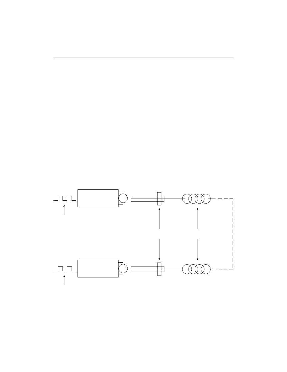
Figure 2-1
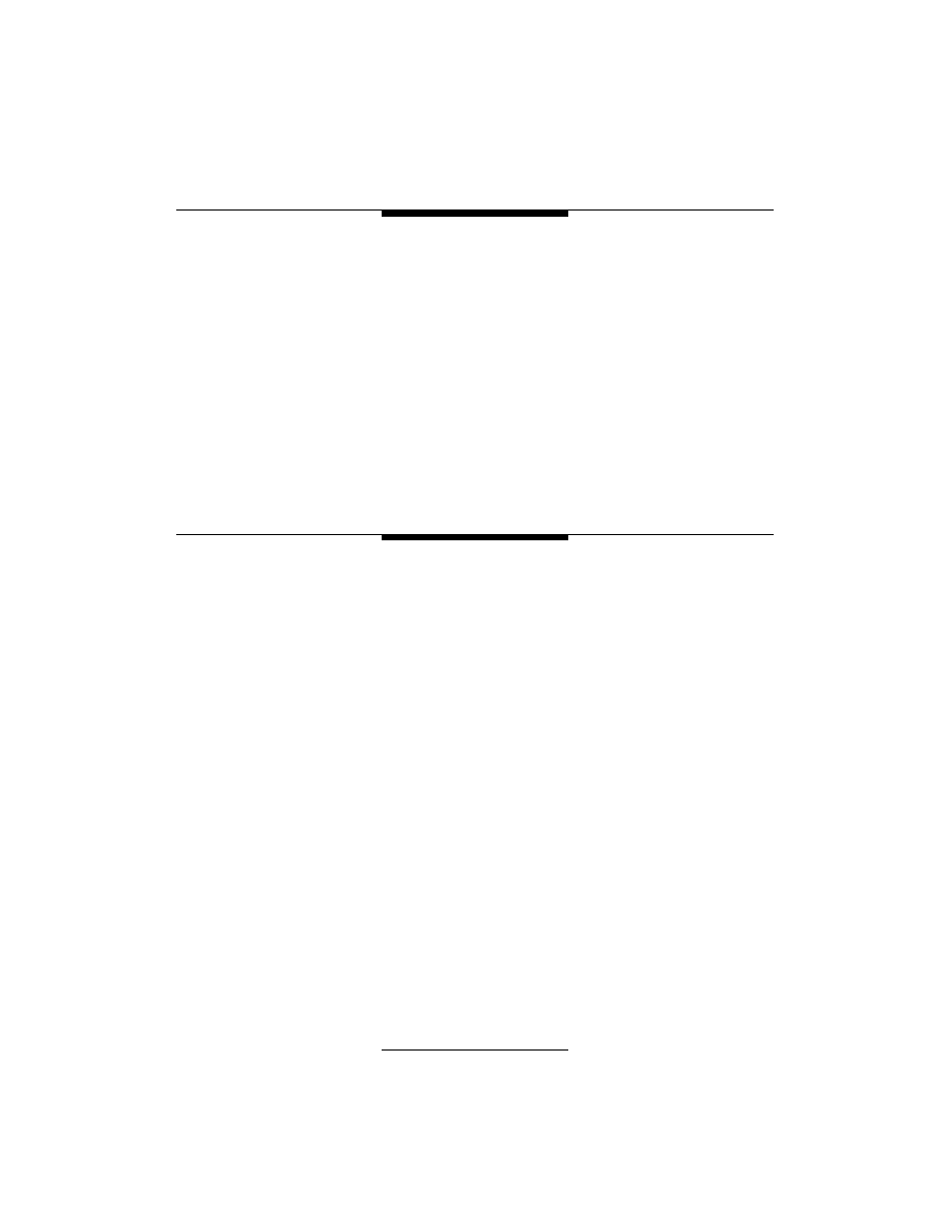
A typical fiber optic data link.
and configurations of cables, each for a specific application: indoor, outdoor, in
the ground, underwater, deep ocean, overhead, and others.
An optical fiber data link is made up of three elements (Figure 2-1):
1. A light source at one end (laser or light-emitting diode [LED]), including
a connector or other alignment mechanism to connect to the fiber. The
light source will receive its signal from the support electronics to convert
the electrical information to optical information.
2. The fiber (and its cable, connectors, or splices) from point to point. The
fiber transports this light to its destination.
3. The light detector on the other end with a connector interface to the
fiber. The detector converts the incoming light back to an electrical sig-
nal, producing a copy of the original electrical input. The support elec-
tronics will process that signal to perform its intended communications
function.
The source and detector with their necessary support electronics are called the
transmitter and receiver, respectively.
16
CHAPTER 2 — BASICS OF FIBER OPTICS
Transmitter
Source
Driver
Input
LED or Laser
Receiver
Output
Photodiode
Preamp/Trigger
Connectors
Cables
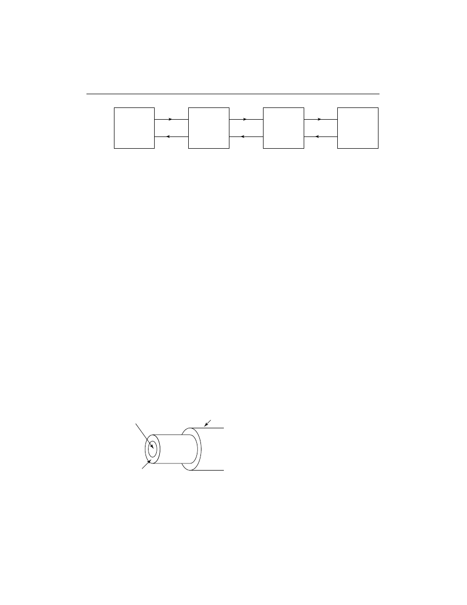
Figure 2-3
Optical fiber construction.
Figure 2-2
Long distance data links require repeaters to regenerate signals.
In long-distance systems (Figure 2-2) the use of intermediate amplifiers may
be necessary to compensate for the signal loss over the long run of the fiber.
Therefore, long-distance networks will be comprised of a number of identical
links connected together. Each repeater consists of a receiver, transmitter, and
support electronics.
OPTICAL FIBER
Optical fiber (Figure 2-3) is comprised of a light-carrying core surrounded by a
cladding that traps the light in the core by the principle of total internal reflec-
tion. By making the core of the fiber of a material with a higher refractive index,
we can cause the light in the core to be totally reflected at the boundary of the
cladding for all light that strikes at greater than a critical angle. The critical angle
is determined by the difference in the composition of the materials used in the
core and cladding. Most optical fibers are made of glass, although some are made
of plastic. The core and cladding are usually fused silica glass covered by a plas-
tic coating, called the buffer, that protects the glass fiber from physical damage
and moisture. Some all-plastic fibers are used for specific applications.
Glass optical fibers are the most common type used in communication appli-
cations. Glass optical fibers can be singlemode or multimode. Most of today’s
telecom and community antenna television (CATV) systems use singlemode
fibers, whereas local area networks (LANs) use multimode graded-index fibers.
CHAPTER 2 — BASICS OF FIBER OPTICS
17
Repeater
Repeater
Repeater
Repeater
Fiber
Fiber
Fiber
Core
Cladding
Buffer Coating
Multimode Step Index
Core
Cladding
Multimode Graded Index
Core
Cladding
Singlemode
Core
Cladding
Figure 2-4
The three types of optical fiber.
Singlemode fibers are smaller in core diameter than multimode fibers and offer
much greater bandwidth, but the larger core size of multimode fiber makes cou-
pling to low cost sources such as LEDs much easier. Multimode fibers may be of
the step-index or graded-index design.
Plastic optical fibers are large core step-index multimode fibers, although
graded-index plastic fiber is under development. Because plastic fibers have a
large diameter and can be cut with simple tools, they are easy to work with and
can use low-cost connectors. Plastic fiber is not used for long distance because it
has high attenuation and lower bandwidth than glass fibers. However, plastic
optical fiber may be useful in the short runs from the street to the home or office
and within the home or office.
There are two basic types of optical fiber—multimode and singlemode (Fig-
ure 2-4). Multimode fiber means that light can travel many different paths (called
modes) through the core of the fiber, entering and leaving the fiber at various
angles. The highest angle that light is accepted into the core of the fiber defines
18
CHAPTER 2 — BASICS OF FIBER OPTICS

the numerical aperture (NA). Two types of multimode fiber exist, distinguished
by the index profile of their cores and how light travels in them (Table 2-1).
Step-index multimode fiber has a core composed completely of one type of
glass. Light travels in straight lines in the fiber, reflecting off the core/cladding
interface. The NA is determined by the difference in the indices of refraction of
the core and cladding and can be calculated by Snell’s law. Since each mode or
angle of light travels a different path, a pulse of light is dispersed while traveling
through the fiber, limiting the bandwidth of step-index fiber.
In graded-index multimode fiber, the core is composed of many different lay-
ers of glass, chosen with indices of refraction to produce an index profile approx-
imating a parabola, where from the center of the core the index of refraction gets
lower toward the cladding. Since light travels faster in the lower index of refrac-
tion glass, the light will travel faster as it approaches the outside of the core. Like-
wise, the light traveling closest to the core center will travel the slowest. A
properly constructed index profile will compensate for the different path lengths
of each mode, increasing the bandwidth capacity of the fiber by as much as 100
times over that of step-index fiber.
Singlemode fiber just shrinks the core size to a dimension about six times the
wavelength of light traveling in the fiber and it has a smaller difference in the
refractive index of the core and cladding, causing all the light to travel in only one
mode. Thus modal dispersion disappears and the bandwidth of the fiber increases
tremendously over graded-index fiber.
FIBER MANUFACTURE
Three methods are used today to fabricate moderate-to-low loss waveguide
fibers: modified chemical vapor deposition (MCVD), outside vapor deposition
(OVD), and vapor axial deposition (VAD).
CHAPTER 2 — BASICS OF FIBER OPTICS
19
Table 2-1
Fiber Types and Typical Specifications
Core/Cladding Attenuation Coefficient (dBkm)
Bandwidth
Fiber Type
Diameter(m)
850 nm
1300 nm
1550 nm
(MHz-km)
Multimode/Plastic
1 mm
(1 dB/m
@665 nm)
Low
Multimode/Step Index
200/240
6
50 @ 850 nm
Multimode/Graded Index 50/125
3
1
600 @1300 nm
62.5/125
3
1
500 @1300 nm
85/125
3
1
500 @1300 nm
100/140
3
1
300 @1300 nm
Singlemode
8-9/125
0.5
0.3
high
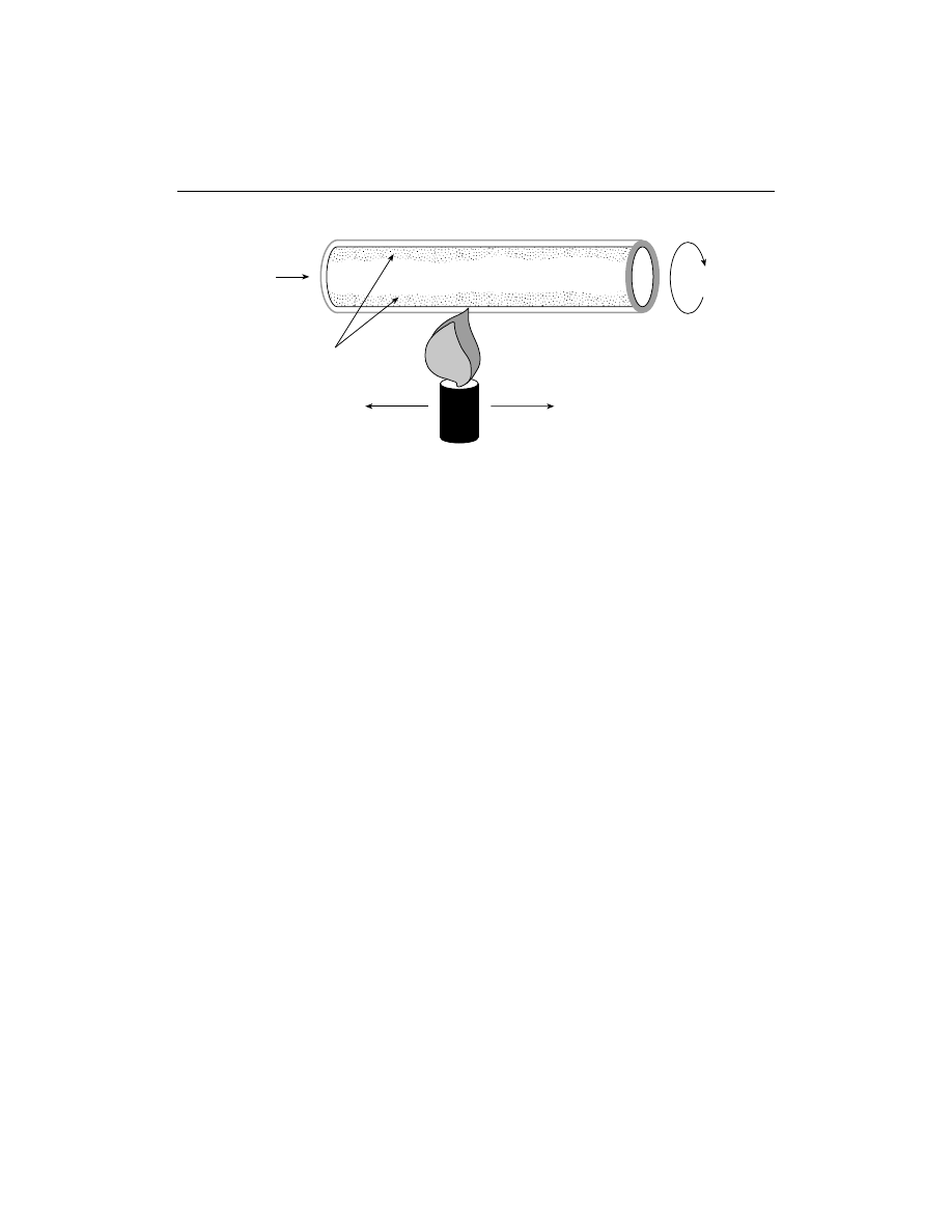
Figure 2-5
Modified chemical vapor deposition (MCVD).
Modified Chemical Vapor Deposition (MCVD)
In MCVD a hollow glass tube, approximately 3 feet long and 1 inch in diameter
(1 m long by 2.5 cm diameter), is placed in a horizontal or vertical lathe and spun
rapidly. A computer-controlled mixture of gases is passed through the inside of
the tube. On the outside of the tube, a heat source (oxygen/hydrogen torch) passes
up and down as illustrated in Figure 2-5.
Each pass of the heat source fuses a small amount of the precipitated gas
mixture to the surface of the tube. Most of the gas is vaporized silicon dioxide
(glass), but there are carefully controlled remounts of impurities (dopants) that
cause changes in the index of refraction of the glass. As the torch moves and the
preform spins, a layer of glass is formed inside the hollow preform. The dopant
(mixture of gases) can be changed for each layer so that the index may be varied
across the diameter.
After sufficient layers are built up, the tube is collapsed into a solid glass rod
referred to as a preform. It is now a scale model of the desired fiber, but much
shorter and thicker. The preform is then taken to the drawing tower, where it is
pulled into a length of fiber up to 10 kilometers long.
Outside Vapor Deposition (OVD)
The OVD method utilizes a glass target rod that is placed in a chamber and spun
rapidly on a lathe. A computer-controlled mixture of gases is then passed between
the target rod and the heat source as illustrated in Figure 2-6. On each pass of the
heat source, a small amount of the gas reacts and fuses to the outer surface of the
rod. After enough layers are built up, the target rod is removed and the remaining
soot preform is collapsed into a solid rod. The preform is then taken to the tower
and pulled into fiber.
20
CHAPTER 2 — BASICS OF FIBER OPTICS
Rotating
Flame
Gases
Hollow Glass Preform
Heat Source Moving
Back and Forth
Soot Deposited
Inside Tube
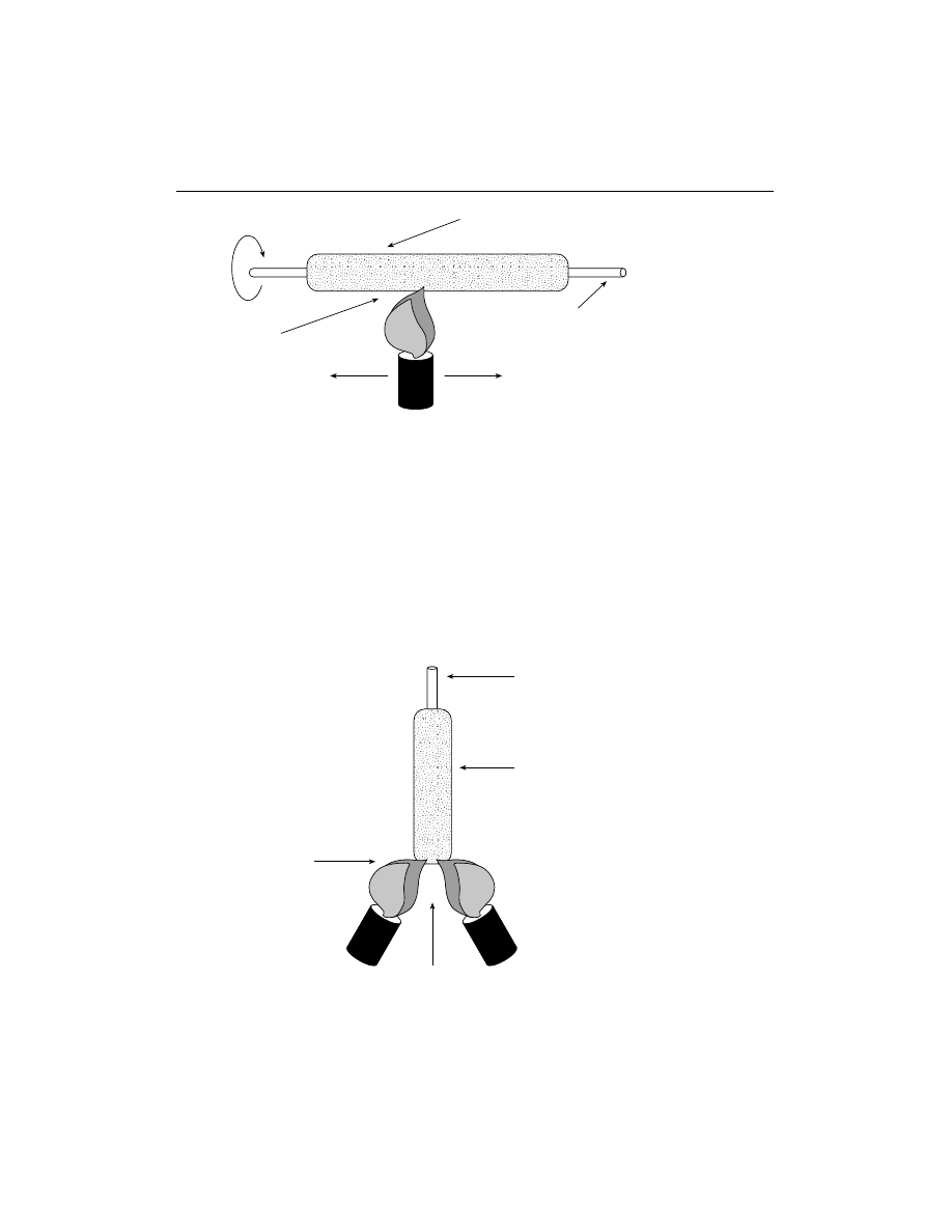
Figure 2-6
Outside vapor deposition (OVD).
Figure 2-7
Vapor axial deposition (VAD).
Vapor Axial Deposition (VAD)
The VAD process utilizes a very short glass target rod suspended by one end. A
computer-controlled mixture of gases is applied between the end of the rod and
the heat source as shown in Figure 2-7. The heat source is slowly backed off as
the preform lengthens due to tile soot buildup caused by gases reacting to the heat
and fusing to the end of the rod. After sufficient length is formed, the target rod
is removed from the end, leaving the soot preform. The preform is then taken to
the drawing tower to be heated and pulled into the required fiber length.
CHAPTER 2 — BASICS OF FIBER OPTICS
21
Rotating
Flame
Gases
Soot Preform
Heat Source Moving
Back and Forth
Target Rod
Gases
Target Rod
Soot Preform
Heat Sources
Moving Down
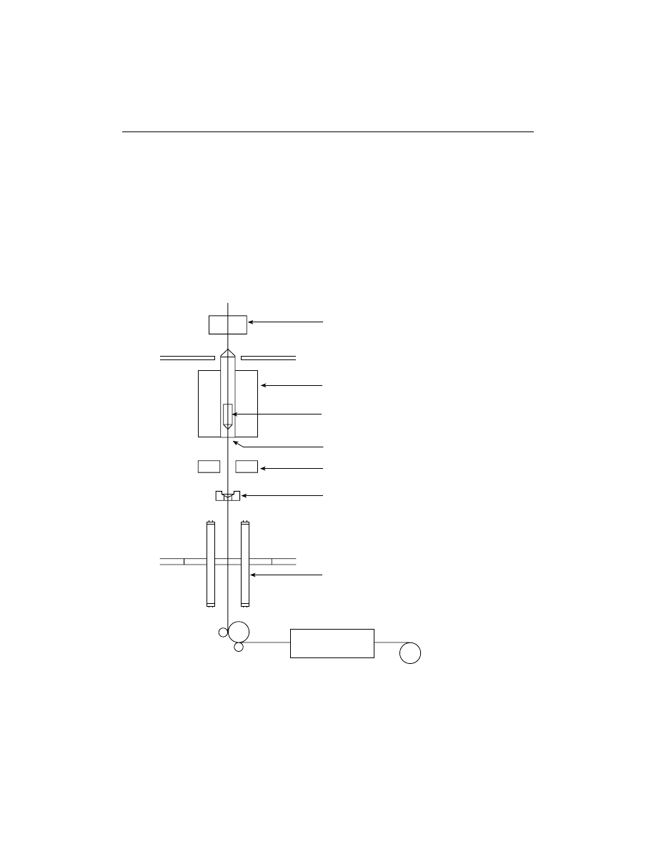
Figure 2-8
Drawing the fiber from the preform and coating the fiber.
Coating the Fiber for Protection
After the fiber is pulled from the preform, a protective coating is applied very
quickly after the formation of the hair-thin fiber (Figure 2-8). The coating is nec-
essary to provide mechanical protection and prevent the ingress of water into any
fiber surface cracks. The coating typically is made up of two parts, a soft inner
coating and a harder outer coating. The overall thickness of the coating varies
between 62.5 and 187.5
µ
m, depending on fiber applications.
22
CHAPTER 2 — BASICS OF FIBER OPTICS
Moveable Blank Holder
Furnace
Fiber Drawing
Diameter Monitor
Coating Applicator
Ultraviolet Lamps
Screen Tester
Preform
CHAPTER 2 — BASICS OF FIBER OPTICS
23
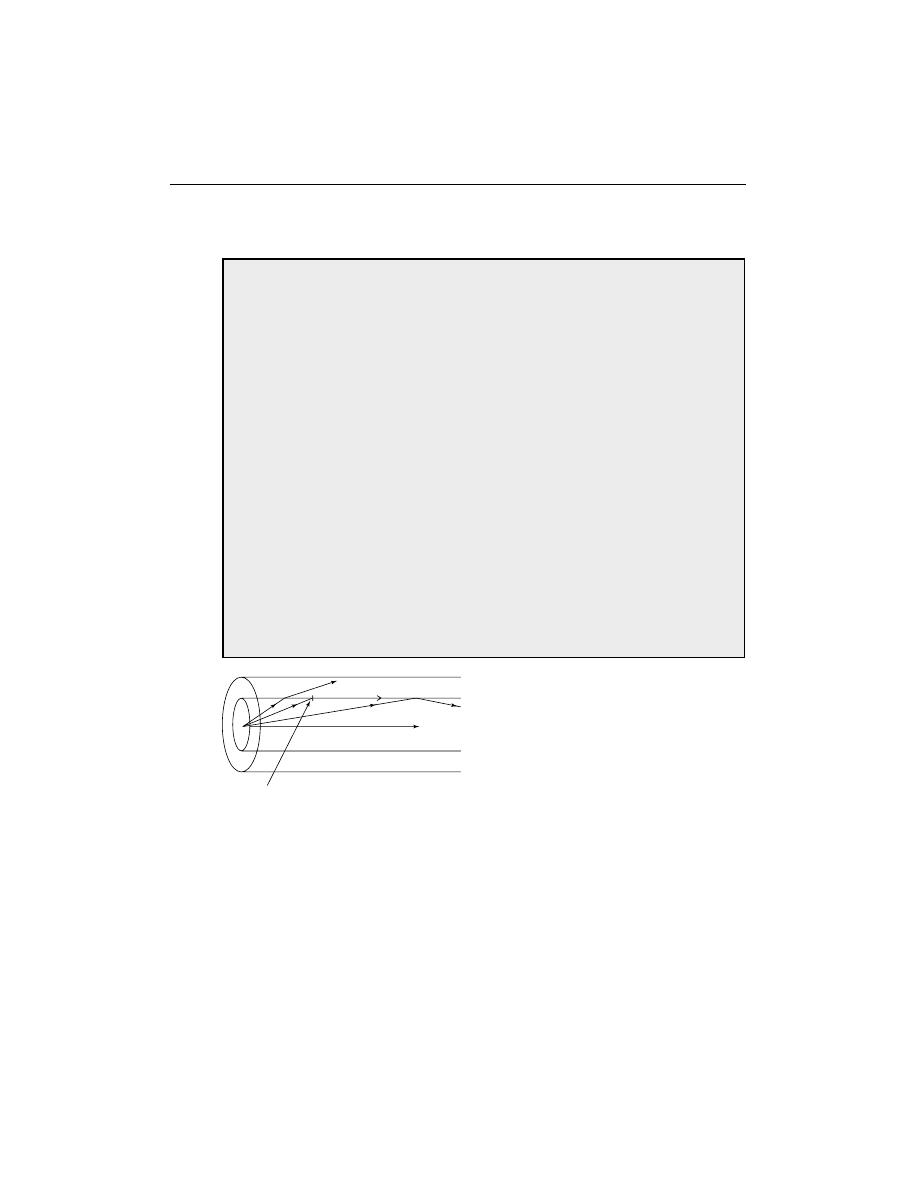
Figure 2-9
Total internal reflection in an optical fiber.
Critical angle
These coatings are typically strippable by mechanical means and must be
removed before fibers can be spliced or connectorized.
ADVANCED STUDY
What Is the Index of Refraction?
The index of refraction of a material is the ratio of the speed of light in vac-
uum to that in the material. In other words, the index of refraction is a
measure of how much the speed of light slows down after it enters the
material. Since light has its highest speed in vacuum, and since light
slows down whenever it enters any medium (water, plastic, glass, crystal,
oil, etc.), the index of refraction of all media is greater than one. For exam-
ple, the index of refraction in a vacuum is 1, that of glass and plastic opti-
cal fibers is approximately 1.5, and water has an index of refraction of
approximately 1.3
When light goes from one material to another of a different index of
refraction, its path will bend, causing an illusion similar to the “bent” stick
stuck into water. At its limits, this phenomenon is used to reflect the light
at the core/cladding boundary of the fiber and trap it in the core (Figure
2-9). By choosing the material differences between the core and cladding,
one can select the angle of light at which this light trapping, called total
internal reflection, occurs. This angle defines a primary fiber specification,
the numerical aperture.
FIBER APPLICATIONS
Each type of fiber has its specific application. Step-index multimode fiber
is used where large core size and efficient coupling of source power are
more important than low loss and high bandwidth. It is commonly used
in short, low-speed datalinks. It may also be used in applications where

radiation is a concern, since it can be made with a pure silica core that is not read-
ily affected by radiation.
Graded-index multimode fiber is used for data communications systems
where the transmitter sources are LEDs. While four graded-index multimode
fibers have been used over the history of fiber optic communications, one fiber
now is by far the most widely used by virtually all multimode datacom
networks—62.5/125
µ
m.
The telephone companies use singlemode fiber for its better performance at
higher bit rates and its lower loss, allowing faster and longer unrepeated links for
long-distance telecommunications. It is also used in CATV, since today’s analog
CATV networks use laser sources designed for singlemode fiber and future
CATV networks will use compressed digital video signals. Almost all other high-
speed networks are using singlemode fiber, either to support gigabit data rates or
long-distance links.
FIBER PERFORMANCE
Purity of the medium is very important for best transmission of an optical signal
inside the fiber. Perfect vacuum is the purest medium we can have in which to
transmit light. Since all optical fibers are made of solid, not hollow, cores, we
have to settle for second best in terms of purity. Technology makes it possible for
us to make glass very pure, however.
Impurities are the unwanted things that can get into the fiber and become a
part of its structure. Dirt and impurities are two different things. Dirt comes to
the fiber from dirty hands and a dirty work environment. This can be cleaned off
with alcohol wipes. Impurities, on the other hand, are built into the fiber at the
time of manufacture; they cannot be cleaned off. These impurities will cause parts
of optical signal to be lost due to scattering or absorption causing attenuation of
the signal. If we have too many impurities in the fiber, too much of the optical
signal will be lost and what is left over at the output of the fiber will not be
enough for reliable communications.
Much of the early research and development of optical fiber centered on
methods to make the fiber purity higher to reduce optical losses. Today’s fibers
are so pure that as a point of comparison, if water in the ocean was as pure, we
would be able to see the bottom on a sunny day.
Optical glass fiber has another layer (or two) that surrounds the cladding,
known as the buffer. The buffer is a plastic coating(s) that provides scratch pro-
tection for the glass below. It also adds to the mechanical strength of the fiber
and protects it from moisture damage. On straight pulling (tension), glass optical
fiber is five times stronger than some steel. But when it comes to twisting and
bending, glass must not be stressed beyond its limits or it will fracture.
24
CHAPTER 2 — BASICS OF FIBER OPTICS
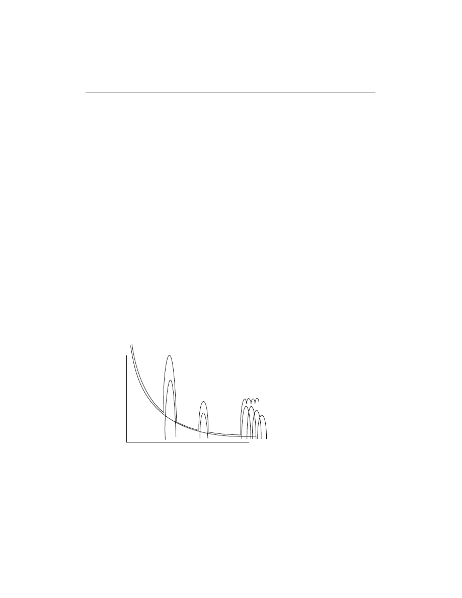
Figure 2-10
Fiber loss mechanisms.
Fiber Attenuation
The attenuation of the optical fiber is a result of two factors—absorption and
scattering (Figure 2-10). Absorption is caused by the absorption of the light and
conversion to heat by molecules in the glass. Primary absorbers are residual OH
+
and dopants used to modify the refractive index of the glass. This absorption
occurs at discrete wavelengths, determined by the elements absorbing the light.
The OH
+
absorption is predominant, and occurs most strongly around 1000 nm,
1400 nm, and above 1600 nm.
The largest cause of attenuation is scattering. Scattering occurs when light
collides with individual atoms in the glass and is anisotrophic. Light that is scat-
tered at angles outside the critical angle of the fiber will be absorbed into the
cladding or scattered in all directions, even transmitted back toward the source.
Scattering is also a function of wavelength, proportional to the inverse fourth
power of the wavelength of the light. Thus, if you double the wavelength of the
light, you reduce the scattering losses by 2
4
or 16 times. Therefore, for long-
distance transmission, it is advantageous to use the longest practical wavelength
for minimal attenuation and maximum distance between repeaters. Together,
absorption and scattering produce the attenuation curve for a typical glass opti-
cal fiber shown in Figure 2-10.
Fiber optic systems transmit in the windows created between the absorption
bands at 850 nm, 1300 nm, and 1550 nm, where physics also allows one to fab-
ricate lasers and detectors easily. Plastic fiber has a more limited wavelength band
that limits practical use to 660-nm LED sources.
CHAPTER 2 — BASICS OF FIBER OPTICS
25
Atten
uation
Scattering
Absorption
Wavelength (nm)
850
1300
1550
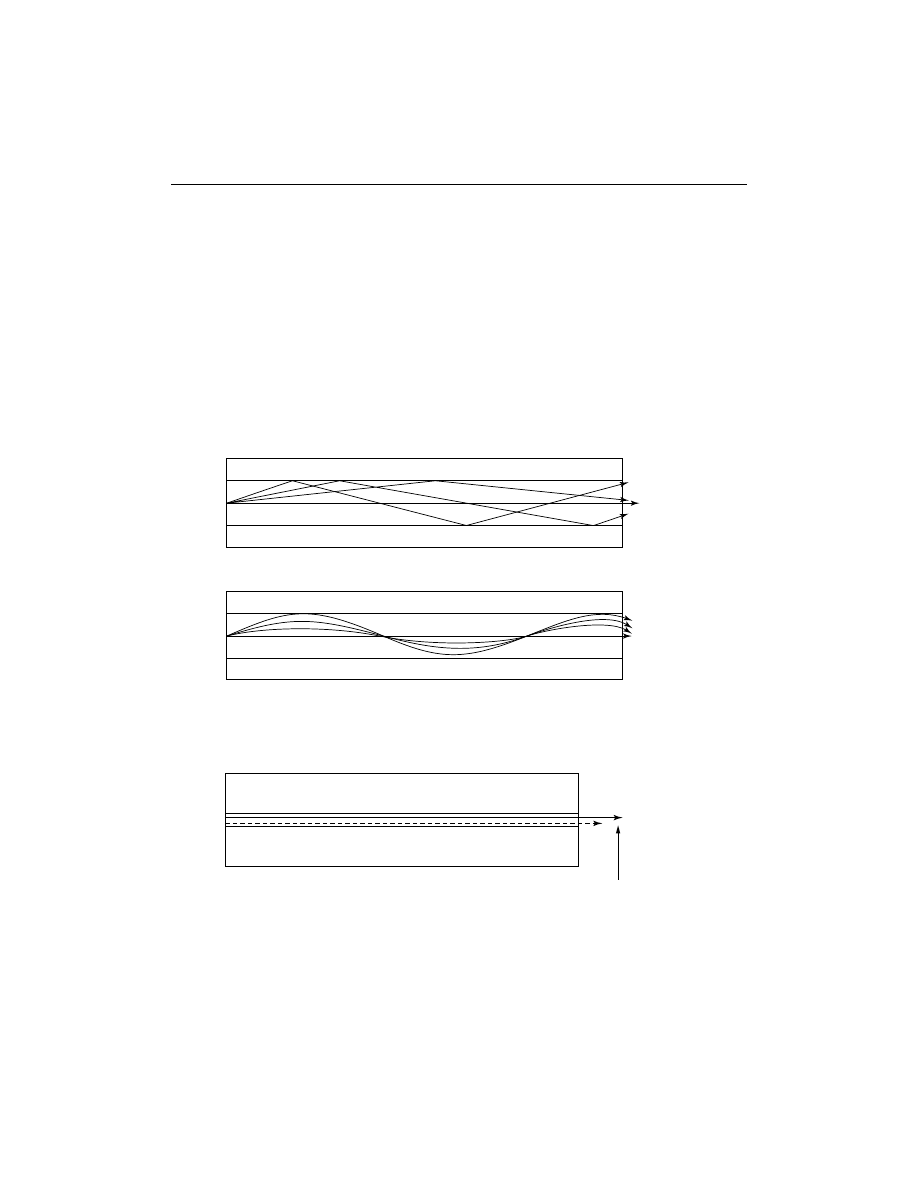
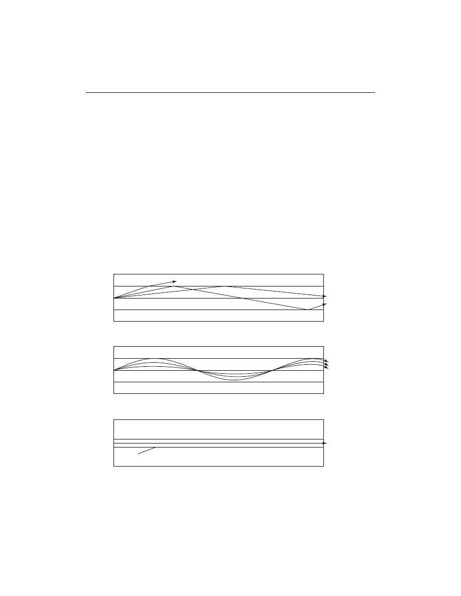
Figure 2-11
Modal dispersion, caused by different path lengths in the fiber, is
corrected in graded-index fiber.
Fiber Bandwidth
Fiber’s information transmission capacity is limited by two separate components of
dispersion: modal (Figure 2-11) and chromatic (Figure 2-12). Modal dispersion
occurs in step-index multimode fiber where the paths of different modes are of
varying lengths. Modal dispersion also comes from the fact that the index profile of
graded-index multimode fiber is not perfect. The graded-index profile was chosen
to theoretically allow all modes to have the same group velocity or transit speed
along the length of the fiber. By making the outer parts of the core a lower index of
refraction than the inner parts of the core, the higher order modes speed up as they
go away from the center of the core, compensating for their longer path lengths.
26
CHAPTER 2 — BASICS OF FIBER OPTICS
Multimode Step Index
Core
Cladding
Multimode Graded Index
Core
Cladding
Figure 2-12
Chromatic dispersion occurs because light of different colors
(wavelengths) travels at different speeds in the core of the fiber.
Longer wavelength goes faster

In an idealized graded-index fiber, all modes have the same group velocity
and no modal dispersion occurs. But in real fibers, the index profile is a piecewise
approximation and all modes are not perfectly transmitted, allowing some modal
dispersion. Since the higher-order modes have greater deviations, the modal dis-
persion of a fiber (and therefore its laser bandwidth) tends to be very sensitive to
modal conditions in the fiber. Thus the bandwidth of longer fibers degrades non-
linearly as the higher-order modes are attenuated more strongly.
The second factor in fiber bandwidth is chromatic dispersion. Remember, a
prism spreads out the spectrum of incident light since the light travels at different
speeds according to its color and is therefore refracted at different angles. The
usual way of stating this is the index of refraction of the glass is wavelength
dependent. Thus, a carefully manufactured graded-index multimode fiber can
only be optimized for a single wavelength, usually near 1300 nm, and light of
other colors will suffer from chromatic dispersion. Even light in the same mode
will be dispersed if it is of different wavelengths.
Chromatic dispersion is a bigger problem with LEDs, which have broad spec-
tral outputs, unlike lasers that concentrate most of their light in a narrow spectral
range. Chromatic dispersion occurs with LEDs because much of the power is
away from the zero dispersion wavelength of the fiber. High-speed systems such
as Fiber Distributed Data Interface (FDDI), based on broad output surface emit-
ter LEDs, suffer such intense chromatic dispersion that transmission over only 2
kilometer of 62.5/125 fiber can be risky.
Modal Effects on Attenuation and Bandwidth
The way light travels in modes in multimode fiber can affect attenuation and
bandwidth of the fiber. In order to model a network or test multimode fiber optic
cables accurately and reproducibly, it is necessary to understand modal distribu-
tion, mode control, and attenuation correction factors. Modal distribution in
multimode fiber is important to measurement reproducibility and accuracy.
CHAPTER 2 — BASICS OF FIBER OPTICS
27
ADVANCED STUDY
What Is Modal Distribution?
In multimode fibers, some light rays travel straight down the axis of the
fiber while all the others wiggle or bounce back and forth inside the core.
In step-index fiber, the off-axis rays, called “higher-order modes,” bounce

28
CHAPTER 2 — BASICS OF FIBER OPTICS
back and forth from core/cladding boundaries as they are transmitted
down the fiber. Since these higher-order modes travel a longer distance
than the axial ray, they are responsible for the dispersion that limits the
fiber’s bandwidth.
In graded-index fiber, the reduction of the index of refraction of the
core as one approaches the cladding causes the higher-order modes to fol-
low a curved path that is longer than the axial ray (the “zero-order mode”).
However, by virtue of the lower index of refraction away from the axis, light
speeds up as it approaches the cladding, thus taking approximately the
same time to travel through the fiber. Therefore the “dispersion,” or varia-
tions in transit time for various modes, is minimized and bandwidth of the
fiber is maximized.
However, the fact that the higher-order modes travel farther in the
glass core means that they have a greater likelihood of being scattered or
absorbed, the two primary causes of attenuation in optical fibers. There-
fore, the higher-order modes will have greater attenuation than lower-order
modes, and a long length of fiber that was fully filled (all modes had the
same power level launched into them) will have a lower amount of power in
the higher-order modes than will a short length of the same fiber.
This change in modal distribution between long and short fibers can
be described as a “transient loss,” and can make big differences in the
measurements one makes with the fiber. It not only changes the modal
distribution, it also changes the effective core diameter and apparent
numerical aperture.
The term “equilibrium modal distribution” (EMD) is used to describe
the modal distribution in a long fiber that has lost the higher-order modes.
A “long” fiber is one in EMD, while a “short” fiber has all its initially
launched higher-order modes.
In the laboratory, a critical optical system is used to fully fill the fiber
modes and a “mode filter,” usually a mandrel wrap that stresses the fiber
and increases loss for the higher-order modes, is used to simulate EMD
conditions. A “mode scrambler,” made by fusion splicing a step-index fiber
into the graded-index fiber near the source, can also be used to fill all
modes equally.
When testing the network cable plant, using an LED or laser source
similar to the one used in the system and short launch cables may provide
as accurate a measurement as is possible under more controlled circum-
stances, since the LED approximates the system source. Alternately, one
may use a mode conditioner (described below) to establish consistent
modal distribution for testing cables.

Mode Conditioners
There are three basic “gadgets” used to condition the modal distribution in mul-
timode fibers: mode strippers that remove unwanted cladding mode light, mode
scramblers that mix modes to equalize power in all the modes, and mode filters
that remove the higher-order modes to simulate EMD or steady-state conditions.
These are discussed in Chapter 17.
REVIEW QUESTIONS
1. The main advantage(s) of optical is (are) its ability to ________________
than other communications media.
a. transport more information
b. transport information faster
c. transport information farther
d. all of the above
2. A fiber optic data link is made up of three elements:
1. ________________
2. ________________
3. ________________
3. Plastic optical fibers are ________________ fibers.
a. singlemode
b. large core step-index
c. large core graded-index
d. either a or b
4. Optical fiber is comprised of three layers:
1. ________________
2. ________________
3. ________________
5. What does 62.5 refer to when written 62.5/125?
a. diameter of the core
b. diameter of the cladding
c. numerical aperture
d. index profile
6. In graded-index optical fiber, the index profile approximates a parabola.
The benefit of this is ________________
a. reduced bandwidth.
b. reduced cross-talk.
c. increased modal dispersion.
d. reduced modal dispersion.
CHAPTER 2 — BASICS OF FIBER OPTICS
29

7. Three methods used to fabricate optical fiber:
1. ________________
2. ________________
3. ________________
8. Match the following fibers to the application they are best suited for:
______ Graded-index multimode
a. long-distance telecommunications
______ Step-index multimode
b. data communications
______ Singlemode
c. efficient source power coupling
9. The largest cause of attenuation is ________________
a. dopants.
b. absorption.
c. moisture.
d. scattering.
10. Optical fiber’s bandwidth, or information transmission capacity, is
limited by two factors:
1. ________________
2. ________________
30
CHAPTER 2 — BASICS OF FIBER OPTICS
Wyszukiwarka
Podobne podstrony:
Basics of Assembler
21 Appendix C Resource Guide to Fiber Optics
Basics Of Hacking 2 VAXs
19 Appendix A Glossary of Fiber Optic Terms
Basics Of Hacking 3 ?ta
Basics Of Hacking Intro
1 The Origins of Fiber Optic Communications
8 Getting Started in Fiber Optics
Basics Of Hacking 1 ?Cs
SHSBC207 BASICS OF AUDITING
BASICS OF ENVIRONMENTAL CHEMISTRY lab no2
Basics of the Coaching Relationship
IF D92 (Industrial Fiber Optics)
v ray basics of the render settings part 4 of 5
IF D95 (Industrial Fiber Optics)
2000 Influence of Fiber Fermentability on Nutrient Digestion in the Dog
IF D97 (Industrial Fiber Optics)
więcej podobnych podstron