Plastic Fiber Optic 50 Mbps Photologic Detector
IF-D97
Plastic Fiber Optic 50 Mbps Photologic Detector
IF-D97
I
N D U S T R I A L
F
I B E R
O
P T I C S
, I
N C
.
•
w w w . i - f i b e r o p t i c s . c o m
43
D
E S C R I P T I O N
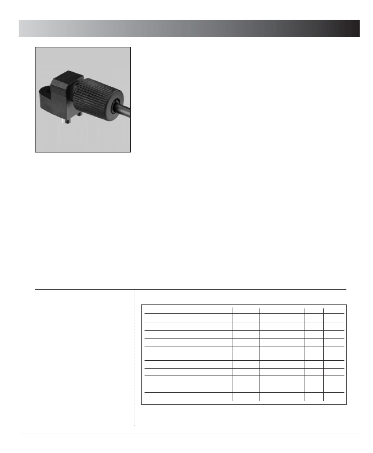
The IF-D97 is a high-speed photologic detector housed in a “connector-less” style
plastic fiber optic package. The detector contains an IC with a photodiode, linear
amplifier and Schmitt trigger featuring an ACT logic compatible totem pole out-
put. Optical response of the IF-D97 extends from 400 to 1050 nm, making it
compatible with a wide range of visible and IR LED and laser diode sources. The
detector package features an internal micro-lens and a precision-molded PBT
housing to ensure efficient optical coupling with standard 1000 µm core plastic
fiber cable.
A
P P L I C AT I O N
H
I G H L I G H T S
The fast transition times of the IF-D97 make it suitable for medium-speed digital
data links. Link distances in excess of 75 meters at data rates of 50 Mbps are pos-
sible using standard 1000 µm core plastic fiber and an IF-E98 LED. The integrated
design of the IF-D97 provides simple, cost-effective implementation in a wide
variety of digital applications.
F
E AT U R E S
◆
No Optical Design Required
◆
Mates with Standard 1000 µm Core Jacketed Plastic Fiber Cable
◆
Internal Micro-Lens for Efficient Coupling
◆
Inexpensive Plastic Connector Housing
◆
Connector-Less Fiber Termination and Connection
◆
Interference-Free Transmission from Light-Tight Housing
◆
Totem-Pole Output
◆
Totally Integrated Solution
◆
Low Current Stand-by Model Available as Special Order
◆
RoHS Compliant
M
A X I M U M
R
AT I N G S
(T
A
= 25°C)
Operating Temperature Range
(T
OP
) ..............................-10° to 70°C
Storage Temperature Range
(T
STG
) ............................- 40° to 85°C
Soldering Temperature
(2 mm from case bottom)
(T
S
) t≤5s ..................................240°C
Supply Voltage, (V
S
)............... -.5 to 7 V
Power Dissipation
(P
TOT
) TA=25°C ..................100 mW
De-rate Above 25°C ...........1.7 mW/°C
A
P P L I CAT I O N S
➤
PC-to-Peripheral Data Links
➤
Motor Controller Triggering
➤
Local Area Networks
➤
Medical Instruments
➤
Automotive Electronics
➤
Digitized Video
➤
Electronic Games
➤
Robotics Communications
➤
Reduction of Lightning and
Voltage Transient Susceptibility
Parameter
Symbol
Min
Typ
Max
Unit
Peak Sensitivity
λPEAK
–
800
–
nm
Spectral Sensitivity (S=10% of S
MAX
)
∆λ
400
–
1050
nm
Operating Voltage
V
CC
4.75
5
5.25
V
Supply Current
I
CC
–
–
40
mA
Light Required to Trigger
1
(V
CC
=5 V,
Er (+)
17
–
–
µW
λ=660 nm)
-17
–
dBm
High Level Output Voltage (I
OH
= -2.0 µA)
V
OH
2
–
–
V
Low Level Output Voltage (I
OL
= .6 mA)
V
OL
–
–
1
V
Output Rise and Fall Times
(f= 10.0 kHz, R
L
= 10 TTL Loads)
tr, tf
–
–
7
ns
Propagation delay time
tp
–
12
–
ns
C
HA R A C T E R I S T I C S
(T
A
=25°C)
N
OTES
:
1. Output is the "L" level (inverted logic) when light is input.
5/2/06
IF-D97
Plastic Fiber Optic 50 Mbps Photologic Detector
IF-D97
Plastic Fiber Optic 50 Mbps Photologic Detector
I
N D U S T R I A L
F
I B E R
O
P T I C S
, I
N C
.
•
w w w . i - f i b e r o p t i c s . c o m
44
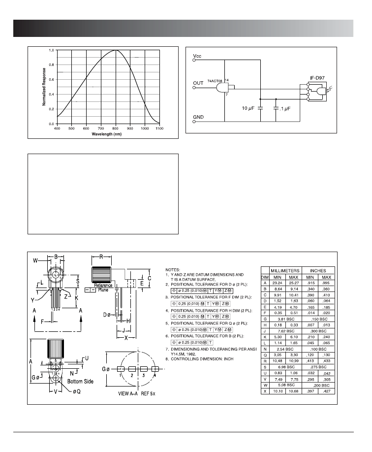
F
IGURE
4.
Case outline.
F
IGURE
3.
Typical interface circuit.
F
I B E R
T
E R M I NAT I O N
I
N S T R U C T IO N S
1. Cut off the ends of the optical fiber with a single-
edge razor blade or sharp knife. Try to obtain a
precise 90-degree angle (square).
2. Insert the fiber through the locking nut and into the
connector until the core tip seats against the internal
micro-lens.
3. Screw the connector locking nut down to a snug fit,
locking the fiber in place.
F
IGURE
1.
Typical detector response versus wavelength.
F
IGURE
2.
Normalized threshold irradiance vs. amb. temp.
T B D
P
ACKAGE
I
DENTIFICATION
:
◆
Black housing w/ copper dot
• PIN 1. Ground
• PIN 2. Q
• PIN 3. Ground
• PIN 4. Vcc
Wyszukiwarka
Podobne podstrony:
IF D92 (Industrial Fiber Optics)
IF D95 (Industrial Fiber Optics)
IF D96 (Industrial Fiber Optics)
IF D91 (Industrial Fiber Optics)
IF D93 (Industrial Fiber Optics)
21 Appendix C Resource Guide to Fiber Optics
2 Basics of Fiber Optics
8 Getting Started in Fiber Optics
statystyka IF cz 5
Marvel Super Heroes Gates of What If Castle Doom Map
IF Bluetooth USB montaż instrukcja PL
Applications and opportunities for ultrasound assisted extraction in the food industry — A review
System industrialny Saint-simona, Współczesne Idee Polityczne
10 0 1 2 Class?tivity What would happen if Instructions
więcej podobnych podstron